JP4751577B2 - Power generation system - Google Patents
Power generation system Download PDFInfo
- Publication number
- JP4751577B2 JP4751577B2 JP2004088013A JP2004088013A JP4751577B2 JP 4751577 B2 JP4751577 B2 JP 4751577B2 JP 2004088013 A JP2004088013 A JP 2004088013A JP 2004088013 A JP2004088013 A JP 2004088013A JP 4751577 B2 JP4751577 B2 JP 4751577B2
- Authority
- JP
- Japan
- Prior art keywords
- fuel
- power generation
- fuel gas
- gas
- chamber
- Prior art date
- Legal status (The legal status is an assumption and is not a legal conclusion. Google has not performed a legal analysis and makes no representation as to the accuracy of the status listed.)
- Expired - Fee Related
Links
Images


Classifications
-
- Y—GENERAL TAGGING OF NEW TECHNOLOGICAL DEVELOPMENTS; GENERAL TAGGING OF CROSS-SECTIONAL TECHNOLOGIES SPANNING OVER SEVERAL SECTIONS OF THE IPC; TECHNICAL SUBJECTS COVERED BY FORMER USPC CROSS-REFERENCE ART COLLECTIONS [XRACs] AND DIGESTS
- Y02—TECHNOLOGIES OR APPLICATIONS FOR MITIGATION OR ADAPTATION AGAINST CLIMATE CHANGE
- Y02E—REDUCTION OF GREENHOUSE GAS [GHG] EMISSIONS, RELATED TO ENERGY GENERATION, TRANSMISSION OR DISTRIBUTION
- Y02E60/00—Enabling technologies; Technologies with a potential or indirect contribution to GHG emissions mitigation
- Y02E60/30—Hydrogen technology
- Y02E60/50—Fuel cells
Landscapes
- Fuel Cell (AREA)
- Hydrogen, Water And Hydrids (AREA)
Description
本発明は、固体酸化物を利用する燃料電池によって発電するシステムに関する。 The present invention relates to a power generation system using a fuel cell that uses a solid oxide.
固体酸化物を利用する燃料電池は効率が高く、数kWから数十kWの発電システムに適しているものと期待されている。固体酸化物型燃料電池を用いて発電するシステムの一例が、特許文献1に記載されている。
固体酸化物を利用する燃料電池は、数kWから数十kWの発電システムに適しているものと期待されているが、必要な発電容量は様々である。4kWの発電能力が必要とされることもあれば、6kWの発電能力が必要とされることもある。電力需要に応じた発電能力を持つ発電システムを提供することが必要である。 A fuel cell using a solid oxide is expected to be suitable for a power generation system of several kW to several tens kW, but the required power generation capacity varies. A power generation capacity of 4 kW may be required, and a power generation capacity of 6 kW may be required. It is necessary to provide a power generation system with a power generation capacity that meets the power demand.
各種の発電能力を持つ発電システムを提供するためには、単位となる発電ユニットを規格化しておき、発電ユニット数を増減することによって必要とされる発電能力を持つ発電システムを構築する手法が一般的であろう。この手法によると、要求される発電能力を持つ発電システムをシステム毎に設計する必要がなくなる。 In order to provide a power generation system with various power generation capacities, it is common to standardize the power generation units as a unit and construct a power generation system with the required power generation capacity by increasing or decreasing the number of power generation units. Probably. According to this method, it is not necessary to design a power generation system having a required power generation capacity for each system.
単位となる発電ユニットの発電能力は小さいことが好ましい。単位となる発電能力が小さいほど、ユニット数を増減することで調整される発電能力の段階幅を細かくでき、多様な電力需要に対してきめ細かく対応することができる。 It is preferable that the power generation capacity of the power generation unit as a unit is small. As the power generation capacity as a unit is smaller, the step width of the power generation capacity adjusted by increasing / decreasing the number of units can be made finer, and it is possible to respond finely to various power demands.
しかしながら、固体酸化物型の燃料電池では、単位となる発電ユニットを小型化することが難しい。固体酸化物型の燃料電池では、都市ガスやLPガスなどを燃料に利用する。都市ガスやLPガスなどの燃料には、エタン、プロパン、ブタンなどが含まれており、そのままでは燃料電池の燃料とすることができない。これらの炭化水素ガスを、一酸化炭素や水素に改質して、燃料電池で利用する。燃料ガスの改質には、通常、排熱利用効率が高くて耐久性に優れている水蒸気改質方式が採用される。水蒸気改質方式では、燃料に水蒸気を混合し、高温の改質触媒が充填された改質器を通過させることで、燃料を改質する。
水蒸気改質方式では、燃料に混合する水量を精度良く管理することが極めて重要である。改質する燃料量に対して水量が少ないと、改質反応を十分に進行することができず、余剰の炭化水素から炭素が析出する。反対に水量が多いと、水が蒸発しきれずに配管内に貯まり配管を閉塞する恐れがある。
燃料ガスの改質に必要とされる水量は非常に小さい。例えば、出力4kwの燃料電池を運転する場合、35cc/分程度の水量が必要とされる。わずかしか必要とされない水量を精度良く管理することは実質上極めて困難である。
固体酸化物型の燃料電池式発電システムを規格化してユニット化する場合、制御可能な水量の最小値の制約から、4kW程度の規模が最小限度であり、これよりも小さい発電能力のユニットを製造しようとしても、あまりに水量が少なくなり、無理なく制御できるユニットを製造することが甚だ困難となる。
However, in a solid oxide fuel cell, it is difficult to reduce the size of a power generation unit as a unit. A solid oxide fuel cell uses city gas, LP gas, or the like as fuel. Fuels such as city gas and LP gas include ethane, propane, butane, etc., and cannot be used as fuel for fuel cells as they are. These hydrocarbon gases are reformed into carbon monoxide and hydrogen and used in fuel cells. For reforming the fuel gas, a steam reforming method is generally adopted that has high exhaust heat utilization efficiency and excellent durability. In the steam reforming method, steam is mixed with fuel, and the fuel is reformed by passing it through a reformer filled with a high-temperature reforming catalyst.
In the steam reforming method, it is extremely important to accurately control the amount of water mixed into the fuel. If the amount of water is small relative to the amount of fuel to be reformed, the reforming reaction cannot proceed sufficiently, and carbon is deposited from excess hydrocarbons. On the other hand, if the amount of water is large, the water may not evaporate and may accumulate in the pipe and block the pipe.
The amount of water required for fuel gas reforming is very small. For example, when operating a fuel cell with an output of 4 kW, a water amount of about 35 cc / min is required. It is practically extremely difficult to accurately control the amount of water that is only required.
When a solid oxide fuel cell power generation system is standardized and unitized, the scale of about 4 kW is the minimum due to the restriction on the minimum amount of water that can be controlled, and a unit with a power generation capacity smaller than this is manufactured. Even if it tries to do so, the amount of water becomes too small, and it becomes extremely difficult to manufacture a unit that can be controlled without difficulty.
しかしながら、単位となる発電ユニットの発電能力が4kW以上であると、多様な電力需要にきめ細かく対応することができない。4kWの発電ユニットで実現できる出力は、4kW、8kW、12kW、・・・である。例えば5kWの電力が要望される場合には、
8kWの発電システムで応えることになり、3kWだけ不必要に大きな発電システムとなってしまう。無駄であるだけでなく、過大に大きくなって設置予定スペースに設置できない事態が発生する。
However, if the power generation capacity of the power generation unit as a unit is 4 kW or more, it is impossible to meticulously respond to various power demands. Outputs that can be realized with a 4 kW power generation unit are 4 kW, 8 kW, 12 kW, and so on. For example, if 5kW power is required,
An 8 kW power generation system will respond, resulting in an unnecessarily large power generation system of 3 kW. Not only is it wasteful, but the situation becomes too large to install in the planned installation space.
発電ユニットをユニット化することによって、多様な電力需要にきめ細かく対応するためには、水量が少なくなりすぎて無理なく制御できるユニットを製造することが甚だ困難となるという限界を打ち破り、小発電能力にまで発電ユニットを小型化しなければならない。
本発明では上記課題を解決する。本発明では、水量が少なくなりすぎて無理なく制御できるユニットを製造することが甚だ困難となるまで発電ユニットを小型化し、それによって多様な電力需要にきめ細かく対応することができる固体酸化物型の燃料電池式発電システムを提案する。
By unitizing the power generation unit, in order to finely respond to various power demands, we break down the limit that it is extremely difficult to manufacture a unit that can be controlled without difficulty because the amount of water is too small, and small power generation capacity The power generation unit must be downsized.
The present invention solves the above problems. In the present invention, the power generation unit is downsized until it becomes extremely difficult to manufacture a unit that can be controlled without difficulty because the amount of water is too small, and thereby a solid oxide fuel that can finely meet various power demands A battery power generation system is proposed.
本発明では、水量が少なくなりすぎて無理なく制御できるユニットを製造することが甚だ困難となるまで発電ユニットを小型化するために、製造困難なものを無理に製造する手法を採用しない。
本発明では、発電システムに必要とされる装置類を研究した結果、ユニットを小型化すると水量が少なくなりすぎて無理なく制御できるユニットを製造することが困難となる装置類と、ユニットを小型化しても製造が困難とならず、むしろ小型化したほうが製造しやすい装置類があることに着目する。そこで、後者の装置類については、多様な電力需要にきめ細かく対応することができるだけの小容量でユニット化する。前者の装置類については、前者のユニット化に対応して小型化すると、水量が少なくなりすぎて無理なく制御できる装置を製造することが甚だ困難となる。そこで、前者の装置類については、後者の複数のユニットに対して共通に利用する単一装置で対応する。すると制御する水量が実用的な量にまで増大し、無理なく製造することが可能となる。
発電システムを、細かくユニット化する装置類と、共通装置で対応する装置類に分けて構築する場合、システム内をガスが流れることから、ユニットの切分けには工夫がいる。ガスの流れが合理的なものに維持され、熱が無駄なく利用できる制約を満たしながら切分けなければならない。また複数ユニットに対応する共通装置については、単位ユニットに規格化することによって安価に多様な需要に応えるユニット化の利点が得られない。前者のユニット化だけで意味あるユニット化になっていなければユニット化の意味がない。
本発明では、上記の問題意識を持って発電システムのユニット化を検討し、ついに上記の課題を克服することに成功した。
In the present invention, in order to reduce the size of the power generation unit until it becomes extremely difficult to manufacture a unit that can be controlled without difficulty because the amount of water is too small, a method for forcibly manufacturing a unit that is difficult to manufacture is not employed.
In the present invention, as a result of studying the devices required for the power generation system, when the unit is downsized, the amount of water becomes too small and it becomes difficult to manufacture a unit that can be controlled easily. However, attention should be paid to the fact that there are devices that are not difficult to manufacture, but rather easier to manufacture when downsized. Therefore, the latter devices are unitized with a small capacity capable of finely responding to various power demands. If the former devices are reduced in size in correspondence with the former unitization, it becomes very difficult to manufacture a device that can be controlled without difficulty because the amount of water becomes too small. Therefore, the former devices are handled by a single device commonly used for the latter plurality of units. Then, the amount of water to be controlled increases to a practical amount, and it becomes possible to manufacture without difficulty.
When building a power generation system into devices that are finely divided into units and devices that are supported by a common device, gas flows through the system, so the unit is devised. The gas flow must be kept reasonable and carved while meeting the constraints that heat can be used without waste. In addition, with regard to a common device corresponding to a plurality of units, it is not possible to obtain the advantage of unitization that meets various demands at low cost by standardizing the unit. There is no point in unitization unless the unitization is meaningful only by the former unitization.
In the present invention, the unitization of the power generation system was studied with the above awareness of the problem, and finally the above problem was successfully overcome.
本発明で得られた発電システムは、固体酸化物型燃料電池を用いて発電するシステムであり、共通に用いる前処理装置と複数の後処理ユニットが組合されて構築されている。
前処理装置は、複数の後処理ユニットに共通に利用され、
(1)燃料ガスを予熱する装置と、
(2)水を供給して蒸発させる蒸発装置と、
(3)燃料ガスと水蒸気を混合する混合装置を備えている。
各々の後処理ユニットは、
(4)水蒸気と混合した燃料ガスを改質する改質装置と、
(5)改質された燃料ガスを酸素と反応させて発電する固体酸化物型燃料電池セルと、
(6)改質された燃料ガスを燃料電池セルに供給する供給装置と、
(7)有酸素ガスを燃料電池セルに供給する供給装置と、
(8)燃料電池セルを通過した燃料ガスを燃焼する装置を備えている。
前処理装置の(3)で得られた水蒸気と混合した燃料ガスは、各々の後処理ユニットの(4)に分配され、各々の後処理ユニットの(8)で得られた燃焼ガスは、前処理装置の(1)と(2)を加熱する。
後処理ユニットが有する改質装置は、予備改質装置と本改質装置で構成されることがある。固体酸化物型燃料電池セルが本改質装置を兼用する場合があり、この場合には予備改質装置だけで改質装置となる。予備改質装置と本改質装置が一つの改質装置に一体化されている場合もある。有酸素ガスの典型例は空気であるが、酸素ガス自体を用いてもよい。
The power generation system obtained by the present invention is a system that generates power using a solid oxide fuel cell, and is constructed by combining a commonly used pre-processing device and a plurality of post-processing units.
The pre-processing device is commonly used for a plurality of post-processing units,
(1) a device for preheating fuel gas;
(2) an evaporator for supplying water to evaporate;
(3) A mixing device for mixing fuel gas and water vapor is provided.
Each aftertreatment unit
(4) a reformer for reforming fuel gas mixed with water vapor;
(5) a solid oxide fuel cell that generates electricity by reacting the reformed fuel gas with oxygen;
(6) a supply device for supplying the reformed fuel gas to the fuel battery cell;
(7) a supply device for supplying aerobic gas to the fuel cell;
(8) A device for burning the fuel gas that has passed through the fuel battery cell is provided.
The fuel gas mixed with the steam obtained in (3) of the pretreatment device is distributed to (4) of each aftertreatment unit, and the combustion gas obtained in (8) of each aftertreatment unit is Heat (1) and (2) of the processing apparatus.
The reformer included in the post-processing unit may be composed of a preliminary reformer and the present reformer. In some cases, the solid oxide fuel cell also serves as the reformer. In this case, only the preliminary reformer serves as the reformer. In some cases, the pre-reformer and the present reformer are integrated into one reformer. A typical example of the aerobic gas is air, but the oxygen gas itself may be used.
(4)〜(8)の装置は、問題なく小型化することができ、むしろ小型化した方が製造しやすい。(2)の装置は、小型化すると水量が少なくなりすぎて無理なく制御できる装置を製造することが甚だ困難となる。(2)については、ユニットに分割せず、単一の装置で対応する。(1)と(3)については、問題なく小型化することができるが、それをユニット化して後処理ユニットに含めると、前処理装置と後処理ユニットの間でガスが何度も往復することになり、配管が複雑化する。配管の単純化のために、(1)と(3)については(2)とともに、共通装置側に切分ける。以上のように切り分けると、結果的には、前処理部分と後処理部分で切分けられ、前処理装置と後処理ユニット間の配管が単純化され、熱の有効利用も促進される。
様々な電力需要量に対して個々に設計して個々に製造すると製造コストが高価になってしまう。規格化しておいた単位ユニットを活用する利点が顕著に得られるのは、(4)から(8)の装置類である。(1)〜(3)の装置類については、例えば配管長を変えることで能力を調整することができ、それぞれの需要量に対応して個々に設計して個々に製造してもあまり製造コストを押し上げない。
本発明の発電システムは、上記の構成を採用したことから、
(A)発電能力に直結する後処理ユニットについては、十分に小型化して多様な電力需要にきめ細かく対応することができ、
(B)微小な水分量を管理する必要がある装置については、複数の後処理ユニットに対して共通に対応する前処理装置に組み込むことから、水量が少なくなりすぎて無理なく制御できる装置を製造することが甚だ困難となるという問題が克服され、
(C)前記(1)〜(3)と(4)〜(8)に切分けると、(1)〜(3)で前処理をし、(4)〜(8)で後処理をすることになり、前処理装置と後処理ユニットの間の配管が単純化されて熱の有効活用が促進され、
(D)(1)〜(3)についてはユニット数で調整する対応が取れなくても、(4)〜(8)がユニット化されることによって規格化しておいた単位ユニットの台数で調整するメリットが十分に得られる。後処理ユニットの装置類については高い耐熱性が要求されるために高価で成形しづらい耐熱材料を用いることが多い。ユニット化して部品の共通化を図るメリットが高い。
The apparatus of (4)-(8) can be reduced in size without a problem, and rather it is easier to manufacture if it is downsized. When the device (2) is downsized, the amount of water becomes too small, and it becomes extremely difficult to manufacture a device that can be controlled without difficulty. Regarding (2), it is not divided into units, but is handled by a single device. (1) and (3) can be downsized without problems, but if they are unitized and included in the post-processing unit, the gas will reciprocate between the pre-processing device and the post-processing unit many times. The piping becomes complicated. For simplification of piping, (1) and (3) are separated to the common device side together with (2). If it cuts as mentioned above, as a result, it cuts into a pre-processing part and a post-processing part, piping between a pre-processing apparatus and a post-processing unit is simplified, and effective use of heat is also promoted.
Manufacturing costs become expensive if they are individually designed and manufactured individually for various power demands. It is the devices (4) to (8) that have the advantage of utilizing the standardized unit units. For the devices (1) to (3), for example, the capacity can be adjusted by changing the pipe length. Do not push up.
Since the power generation system of the present invention employs the above configuration,
(A) About the post-processing unit that is directly connected to the power generation capacity, it can be sufficiently miniaturized to respond precisely to various power demands,
(B) For devices that need to manage minute amounts of water, since they are built into pre-processing devices that support multiple post-processing units, the amount of water is too small and can be controlled without difficulty. Overcoming the problem of being extremely difficult to do,
(C) If it divides into said (1)-(3) and (4)-(8), it will pre-process in (1)-(3) and will post-process in (4)-(8). And the piping between the pre-treatment device and the post-treatment unit is simplified and effective utilization of heat is promoted,
(D) (1) to (3) are adjusted by the number of unit units that have been standardized by unitizing (4) to (8) even if it is not possible to adjust by the number of units. Benefits can be fully obtained. Since high heat resistance is required for the devices of the post-processing unit, an expensive heat-resistant material that is difficult to form is often used. There is a high merit to unitize parts by unitization.
燃料の改質には、予備改質と本改質がある。本明細書では、燃料ガスに含まれる炭素数2以上の炭化水素を水蒸気改質法によってメタンや水素や一酸化炭素に分解することを予備改質といい、燃料ガスに含まれるメタンを水蒸気改質法によって水素や一酸化炭素に分解することを本改質という。
本発明の主眼は、燃料ガスの予備改質および本改質のために混合する水分量の調整を、単一の前処理装置で一括して実施する点にある。
上記(4)の改質装置は、通常は予備改質装置と本改質装置を備えるが、改質装置の構成はこれに限定されるものではない。
例えば固体酸化物型燃料電池では、燃料電池セルが高温となるため、その電極上でメタンを水素や一酸化炭素に改質することもできる。このため後処理ユニットにおいて、本改質装置を用いることなく、予備改質した燃料ガスを直接燃料電池セルへ送出してもよい。あるいは、一つの改質装置で燃料ガスの予備改質と本改質を実施してもよい。
Fuel reforming includes pre-reforming and main reforming. In this specification, decomposition of hydrocarbons having 2 or more carbon atoms contained in fuel gas into methane, hydrogen or carbon monoxide by the steam reforming method is called pre-reformation, and methane contained in fuel gas is steam-modified. Decomposition into hydrogen and carbon monoxide by the quality method is called this reforming.
The main point of the present invention is that the adjustment of the amount of water mixed for the preliminary reforming of the fuel gas and the main reforming is collectively performed by a single pretreatment device.
The reformer (4) usually includes a preliminary reformer and a main reformer, but the configuration of the reformer is not limited to this.
For example, in a solid oxide fuel cell, since the temperature of the fuel cell becomes high, methane can be reformed to hydrogen or carbon monoxide on the electrode. Therefore, the pre-reformed fuel gas may be sent directly to the fuel cell without using the present reformer in the post-processing unit. Alternatively, the preliminary reforming and the main reforming of the fuel gas may be performed with one reformer.
各々の後処理ユニットが、1〜3kWの発電能力に選定されていることが好ましい。後処置ユニットと前処理装置に切分けないでユニット化すると、前記したように4kW以下に小型化することが難しい。本発明によると、後処置ユニットでは水分を管理する必要がないことから4kW以下に小型化することに対する制約がない。
各々の後処理ユニット発電能力が1〜3kWに選定されていると、多様な電力需要にきめ細かく対応することができる。3kW単位で調整できれば、過大サイズになって設置予定場所に設置できないという事態が減少する。2kW単位で調整できれば、多様な電力需要に対してほぼ過不足なく対応することができる。
特に、2kW程度の後処理ユニットと、3kW程度の後処理ユニットの2種類を用意しておくことが極めて好ましい。上記2種類の後処理ユニットと、前処理装置を組み合わせることで、4kW(2kWの後処理ユニットを2つ接続する)、5kW(2kWの後処理ユニットと3kWの後処理ユニットを接続する)、6kW(3kWの後処理ユニットを2つ接続するか、あるいは2kWの後処理ユニットを3つ接続する)、・・・と、さまざまな出力の発電システムを実現することができる。
Each aftertreatment unit is preferably selected for a power generation capacity of 1 to 3 kW. If the unit is formed without separating the post-treatment unit and the pre-treatment device, it is difficult to reduce the size to 4 kW or less as described above. According to the present invention, since there is no need to manage moisture in the post-treatment unit, there is no restriction on downsizing to 4 kW or less.
When each post-processing unit power generation capacity is selected to be 1 to 3 kW, it is possible to meticulously respond to various power demands. If the adjustment can be made in units of 3 kW, the situation of being oversized and unable to be installed at the planned installation location is reduced. If it can be adjusted in units of 2 kW, it can respond to various power demands almost without excess or deficiency.
In particular, it is highly preferable to prepare two types of post-processing units of about 2 kW and post-processing units of about 3 kW. By combining the above two types of post-processing units and pre-processing devices, 4 kW (two 2 kW post-processing units are connected), 5 kW (2 kW post-processing units and 3 kW post-processing units are connected), 6 kW (Two 3kW post-processing units are connected, or three 2kW post-processing units are connected), and so on, and various power generation systems can be realized.
各々の後処理ユニットは、(5)〜(8)を収容する略立方体のケースと、そのケースから下方に突出する予備改質器を備えていることが好ましい。この場合、下方に突出する予備改質装置が前処理装置のケース内に収容された状態で組合される。
後処理ユニットは、(5)〜(8)を収容する略立方体のケースと予備改質装置が別々に出荷され、設置場所で後処理ユニットが完成してもよい。この場合、予備改質装置を前処理装置のケース内に収容した状態で出荷してもよい。
この形状を採用すると、熱の有効利用が促進される。
Each of the aftertreatment units preferably includes a substantially cubic case that accommodates (5) to (8), and a pre-reformer that protrudes downward from the case. In this case, the pre-reformer protruding downward is combined in a state of being accommodated in the case of the pretreatment device.
The post-processing unit may be shipped in a substantially cubic case accommodating (5) to (8) and a pre-reformer separately, and the post-processing unit may be completed at the installation location. In this case, the pre-reformer may be shipped in a state of being accommodated in the case of the pretreatment device.
Employing this shape promotes effective use of heat.
前処理装置の(1)と(3)は、複数個の後処理ユニットの下方を横断するように伸びていることが好ましい。
この場合、複数個の後処理ユニットから放出される燃焼ガスを有効に利用して前処理装置が必要とする加熱処理に利用することが可能となる。
It is preferable that (1) and (3) of the pretreatment apparatus extend so as to cross the lower part of the plurality of posttreatment units.
In this case, the combustion gas emitted from the plurality of post-processing units can be used effectively for the heat treatment required by the pre-processing apparatus.
前記前処理装置が、各々の後処理ユニットの(8)から放出される燃焼ガスを受入れて放出するケースと、水蒸気と混合して加熱された燃料ガスを、各々の後処理ユニットの(4)に分配する装置をさらに備えており、前記前処理装置の(1)が、前記ケース内で伸びており、通過する燃料ガスを燃焼ガスで加熱する第1伝熱管を備えており、前記前処理装置の(2)が、第1伝熱管の下流に位置しており、水を滴下させる装置を備えており、前記前処理装置の(3)が、前記ケース内で伸びており、加熱された燃料ガスと水蒸気を混合しながらさらに加熱する第2伝熱管を備えていることが好ましい。
上記のように前処理装置を構成すると、前処理装置へ流入する燃焼ガスは、ケース内を流れて、第1伝熱管、蒸発装置、第2伝熱管を加熱した後に、装置外へ排出される。燃焼ガスを熱源として、燃料ガスの加熱と、水の蒸発と、水蒸気と混合した燃料ガスの加熱を行うことができる。上記の前処理装置を備える発電システムでは、簡易な装置構成で、燃焼ガスの熱を有効に利用することできる。
The pretreatment device receives and discharges the combustion gas emitted from (8) of each aftertreatment unit , and the fuel gas mixed with water vapor and heated (4) of each aftertreatment unit. And (1) of the pretreatment device is provided with a first heat transfer tube that extends in the case and heats the passing fuel gas with combustion gas. (2) of the device is located downstream of the first heat transfer tube and is provided with a device for dripping water, and (3) of the pretreatment device is extended in the case and heated. It is preferable to include a second heat transfer tube that is further heated while mixing the fuel gas and water vapor.
When the pretreatment device is configured as described above, the combustion gas flowing into the pretreatment device flows through the case, heats the first heat transfer tube, the evaporator, and the second heat transfer tube, and then is discharged outside the device. . By using the combustion gas as a heat source, heating of the fuel gas, evaporation of water, and heating of the fuel gas mixed with water vapor can be performed. In the power generation system including the above pretreatment device , the heat of the combustion gas can be effectively used with a simple device configuration.
本発明の固体酸化物型の燃料電池式発電システムによれば、水量を制御する共通の前処理装置と複数の発電ユニット(後処理ユニット)が組み合わせて利用されるため、発電ユニットを無理なく小型化することができ、それによって多様な電力需要にきめ細かく対応することができる。 According to the solid oxide fuel cell power generation system of the present invention, since a common pretreatment device for controlling the amount of water and a plurality of power generation units (post-treatment units) are used in combination, the power generation unit can be made compact without difficulty. It can respond to various electric power demands finely.
(形態1)前処理装置は、燃料ガスを予熱する装置と、水を供給して水蒸気を発生させる蒸発装置と、燃料ガスと水蒸気を混合しながらさらに予熱する混合装置を備えている。水蒸気と混合する前の燃料ガスを予熱しておくと、水が蒸発し易い。
(形態2)蒸発装置は、予熱された燃料ガスの通路であり、上部から滴下する水を予熱された燃料ガス及び燃焼ガスの熱で蒸発させる。蒸発装置の内部には蓄熱材が堆積されており、蒸発しないで滴下した水を蒸発させる。
(形態3)後処理ユニットから放出された燃焼ガスが、燃料ガスを予熱する。後処理ユニットから排出される燃焼ガスは高温であり、その熱を利用して燃料ガスを予熱することで発電効率は向上する。
(形態4)燃料ガスを予熱する装置は、燃焼ガス流路を横断する伝熱管を備えており、その伝熱管を燃料ガスが通過する間に燃料ガスが燃焼ガスで予熱される。
燃料ガスの予熱装置の構成が簡易なものとなり、発電システムの製造が容易となる。
(形態5)前記伝熱管は、管の長さの異なる他の伝熱管と取替可能である。
燃料ガスに供給する水分量は、改質器に供給する燃料量に比例する。燃料量は、発電システムの出力に比例し、後処理ユニットのユニット数に応じて変化する。従って、前処理装置の蒸発装置で蒸発させる水分量と、前処理装置の燃料ガス予熱装置で予熱する燃料量も変化する。水分量が多いほど、水を蒸発させるに要する熱量は大きい。また、燃料量が多いほど、燃料を予熱するために要する熱量は大きい。
従って後処理ユニットの個数が多いほど、前処理装置で必要とされる余熱量は多く必要になる。
本発明の発電システムでは、伝熱管の長さを変えることによって、余熱量を調整する。後処理ユニットの数を増やして、発電システムの出力を増加させる場合、伝熱管を長いものに変えるだけで対応することができる。
(形態6)前処理装置の混合装置は、燃焼ガス流路を横断する伝熱管を備えており、その伝熱管を燃料ガスと水分が通過する間に両者を混合して燃焼ガスで予熱する。後処理ユニットから排出される燃焼ガスが有効に活用され、発電効率が向上する。
(形態7)混合装置の伝熱管は、内部に螺旋状の攪拌壁を備えており、燃料ガスと水分が通過する間に両者を混合する。
(形態8)混合装置の伝熱管は、管の長さの異なる他の伝熱管と取替可能であることが望ましい。後処理ユニットの数を増やして、発電システムの出力を増加させる場合に、伝熱管を長いものに変えるだけで対応することができる。
(形態9)予備改質装置は、水蒸気と混合された燃料ガスを導入する導入口と、導入された燃料ガスの一部を導出する導出口を備え、その導出口から他の予備改質装置へ燃料ガスを供給可能であることが望ましい。
複数の後処理ユニットは、それぞれに予備改質装置を備えており、各予備改質装置に燃料ガスを分配する必要がある。予備改質装置に、改質しないで燃料ガスを導出する導出口を設けることで、その予備改質装置で改質する燃料ガスと、改質することなく他の予備改質装置に送出する燃料ガスとを分配することが可能となり、予備改質装置の外部で燃料ガスを供給する配管を分岐させる必要がなくなる。前処理装置内に形成される燃料ガス供給配管の構成を簡素化することができ、前処理装置の製造が容易となる。
(Mode 1) The pretreatment device includes a device for preheating the fuel gas, an evaporator for supplying water to generate water vapor, and a mixing device for further preheating while mixing the fuel gas and water vapor. If the fuel gas before mixing with water vapor is preheated, the water is likely to evaporate.
(Embodiment 2) The evaporation device is a passage of preheated fuel gas, and evaporates water dripped from the upper part with heat of the preheated fuel gas and combustion gas. A heat storage material is deposited inside the evaporation device, and the dropped water is evaporated without evaporation.
(Mode 3) The combustion gas released from the aftertreatment unit preheats the fuel gas. The combustion gas discharged from the post-processing unit is at a high temperature, and the power generation efficiency is improved by preheating the fuel gas using the heat.
(Mode 4) An apparatus for preheating fuel gas includes a heat transfer tube that crosses the combustion gas flow path, and the fuel gas is preheated with the combustion gas while the fuel gas passes through the heat transfer tube.
The configuration of the fuel gas preheating device is simplified, and the production of the power generation system is facilitated.
(Mode 5) The heat transfer tube can be replaced with another heat transfer tube having a different length.
The amount of water supplied to the fuel gas is proportional to the amount of fuel supplied to the reformer. The amount of fuel is proportional to the output of the power generation system and changes according to the number of post-processing units. Therefore, the amount of water evaporated by the evaporator of the pretreatment device and the amount of fuel preheated by the fuel gas preheating device of the pretreatment device also change. The greater the amount of moisture, the greater the amount of heat required to evaporate the water. Also, the greater the amount of fuel, the greater the amount of heat required to preheat the fuel.
Therefore, the greater the number of post-processing units, the greater the amount of residual heat required in the pre-processing apparatus.
In the power generation system of the present invention, the amount of residual heat is adjusted by changing the length of the heat transfer tube. Increasing the output of the power generation system by increasing the number of post-processing units can be handled simply by changing the heat transfer tube to a longer one.
(Mode 6) The mixing device of the pretreatment device includes a heat transfer tube that crosses the combustion gas flow path, and while the fuel gas and moisture pass through the heat transfer tube, both are mixed and preheated with the combustion gas. The combustion gas discharged from the post-processing unit is effectively used, and the power generation efficiency is improved.
(Mode 7) The heat transfer tube of the mixing device includes a spiral stirring wall inside, and mixes both while the fuel gas and moisture pass.
(Mode 8) It is desirable that the heat transfer tube of the mixing device can be replaced with another heat transfer tube having a different length. When increasing the number of post-processing units and increasing the output of the power generation system, it is possible to respond by simply changing the heat transfer tube to a longer one.
(Embodiment 9) The pre-reformer has an inlet for introducing a fuel gas mixed with water vapor, and an outlet for deriving a part of the introduced fuel gas, from the outlet to another preliminary reformer It is desirable to be able to supply fuel gas to
Each of the plurality of post-treatment units includes a pre-reformer, and it is necessary to distribute fuel gas to each pre-reformer. By providing the pre-reformer with a lead-out port for deriving the fuel gas without reforming, the fuel gas reformed by the pre-reformer and the fuel sent to another pre-reformer without reforming It becomes possible to distribute the gas, and there is no need to branch the piping for supplying the fuel gas outside the pre-reformer. The configuration of the fuel gas supply pipe formed in the pretreatment device can be simplified, and the production of the pretreatment device becomes easy.
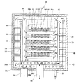
本発明を具現化した発電システムの実施例を、図面を参照しながら説明する。図1は、本実施例に係る発電システムの縦断面図であり、図2は図1のII−II線断面図であり、図3は図1のIII−III線断面図である。また図4は、本実施例に係る発電ユニット10の縦断面図であり、図5は図4のV−V線断面図であり、図6は図4のVI−VI線断面図であり、図7は図5の部分断面拡大図である。
An embodiment of a power generation system embodying the present invention will be described with reference to the drawings. 1 is a longitudinal sectional view of a power generation system according to the present embodiment, FIG. 2 is a sectional view taken along the line II-II in FIG. 1, and FIG. 3 is a sectional view taken along the line III-III in FIG. 4 is a longitudinal sectional view of the
図1〜図3に示すように、本実施例の発電システム2は、共通に利用する1つの供給ユニット(前処理装置)110と、3つの発電ユニット(後処理ユニット)10a、10b、10cを備えている。
発電ユニット10a、10b、10cは共通構成であり、以下では発電ユニット10として、図4から図7を用いて後に共通に説明する。
供給ユニット110は、略直方体形状の金属性の箱であり、その内部に水蒸気混合部112と、予備改質器114a、114b、114cと、空気供給管116を備えている。
供給ユニット110の上部には、発電ユニット10a、10b、10cが配置されている。発電ユニット10a、10b、10cのそれぞれには、供給ユニット110から予備改質された燃料および空気が供給され、燃焼ガスを供給ユニット110に送出する。
なお本実施例中では、発電ユニット10a、10b、10cと各発電ユニットに対応する予備改質器114a、114b、114cとの組が、後処理ユニットに相当する。また、供給ユニット110から予備改質器114a、114b、114cを除いた部分が、前処理装置に相当する。
As shown in FIGS. 1 to 3, the
The
The
On the upper part of the
In the present embodiment, a set of the
水蒸気混合部112は供給ユニット110内の前方に配置されており、その後ろにブラケット136及び発電ユニット10a、10b、10cによって保持された予備改質器114a、114b、114cが配置され、その後ろに空気供給管116が配置され、その後ろに燃焼ガス排出口150が設けられている。
水蒸気混合部112は、供給される燃料ガスに、水を気化して混合し、生成される水蒸気混合燃料ガスを予備改質器114a、114b、114cへ送出する。水蒸気混合部112は、燃料導入管120、水導入管122、燃料昇温室124、燃料昇温管126、水蒸発室128、水蒸気混合燃料昇温管130、水蒸気混合燃料混合室132、水蒸気混合燃料供給管134を備えている。
燃料昇温室124は、直方体形状の金属性の箱であり、燃料導入管120が接続している。都市ガスやLPガスといった燃料が、発電システム2の外部で脱硫された後、燃料導入管120を経由して燃料昇温室124へ供給される。燃料昇温室124の外部には、高温の燃焼ガスが下方から上方に向けて流れており、燃料昇温室124へ供給された燃料ガスは、燃焼ガスとの熱交換によって昇温され、燃料昇温管126へ送出される。
燃料昇温管126は、ベローズ管を略U字状に折り曲げた形状をしており、一方の端部が燃料昇温室124に接続され、他方の端部を水蒸発室128に接続されている。燃料昇温室124から流入する燃料ガスは、燃料昇温管126を通り、水蒸発室128へ流入する。燃料昇温管126の外部には、高温の燃焼ガスが下方から上方に向けて流れており、燃料昇温管126内を通過する燃料ガスは、燃焼ガスとの熱交換によって昇温され、水蒸発室128へ流入する。燃料昇温管126は、3台の発電ユニット10a、10b、10cの下方を横断するように伸びており、3台の発電ユニット10a、10b、10cから放出される燃焼ガスで加熱される。
水蒸発室128は、直方体形状の金属性の箱であり、内部には蓄熱材が堆積している。水蒸発室128の外部には、高温の燃焼ガスが下方から上方に向けて流れており、水蒸発室128の側壁と燃焼ガスとの熱交換によって、水蒸発室128は加熱される。水蒸発室128の上部には、水導入管122が連通しており、水導入管122から脱イオン水が供給される。供給された脱イオン水は、図示されない給水ポンプで燃料ガスに対して過不足のない量に制御され、水蒸発室128内へ滴下する。水蒸発室128内へ滴下した水は、燃料昇温管126から流入する高温の燃料ガスと混合して気化する。水蒸発室128で気化した水が混合した燃料ガスは、水蒸気混合燃料昇温管130へ流入する。
水蒸発室128の内部には、アルミナの球体が蓄熱材として堆積しており、その蓄熱材は水蒸発室128内の温度が高い場合には吸熱し、水蒸発室128内の温度が低い場合には放熱する。従って、水蒸発室128内は高温で略一定の温度に安定する。
水蒸気混合燃料昇温管130は、ベローズ管を略U字状に折り曲げた形状をしており、一方の端部が水蒸発室128に接続され、他方の端部を水蒸気混合燃料混合室132に接続されている。水蒸発室128から流入する水蒸気混合燃料ガスは、水蒸気混合燃料昇温管130を通り、水蒸気混合燃料混合室132へ流入する。水蒸気混合燃料昇温管130の外部には、高温の燃焼ガスが下方から上方に向けて流れており、水蒸気混合燃料昇温管130内を通過する水蒸気混合燃料ガスは、燃焼ガスとの熱交換によって昇温される。また、管の内面の突起により、管内を通過する水蒸気混合燃料ガスに乱流が発生し、水蒸気混合燃料ガスは攪拌されて、水蒸気と燃料の混合比が均一化する。水蒸気混合燃料昇温管130内を通過した水蒸気混合燃料ガスは、水蒸気混合燃料混合室132へ流入する。
水蒸気混合燃料混合室132は、直方体形状の金属性の箱である。上部には水蒸気混合燃料昇温管130が接続しており、下部には水蒸気混合燃料供給管134が接続している。水蒸気混合燃料混合室132の外部には、高温の燃焼ガスが下方から上方に向けて流れており、水蒸気混合燃料混合室132内を通過する水蒸気混合燃料ガスは、燃焼ガスとの熱交換によって昇温される。水蒸気混合燃料混合室132の大きさは、水蒸気混合燃料昇温管130の管径にくらべ十分に大きく、水蒸気混合燃料昇温管130から流入する水蒸気混合燃料ガスは、水蒸気混合燃料混合室132で整流され、水蒸気混合燃料供給管134に供給される。
水蒸気混合燃料供給管134は、管の内面に螺旋状の攪拌壁を備えており、燃料ガスと水分が通過する間に両者を混合する。水蒸気混合燃料供給管134は、一方の端部が水蒸気混合燃料混合室132に接続し、ブラケット136を貫通して、他方の端部が予備改質器114cへ接続している。
The
The
The fuel
The fuel
The
In the
The steam-mixed
The steam mixed
The steam-mixed
予備改質器114a、114b、114cはそれぞれ発電ユニット10a、10b、10cの下部に配置され、ブラケット136及び発電ユニット10a、10b、10cによって保持されている。
以下では添字を省略して共通に説明する。予備改質器114は、発電ユニット10から下向きに延びる燃焼ガス導出管58の下側端部から上方に向けて、燃焼ガス導出管58の外側を包囲する金属性の箱であり、燃焼ガス導出管58に対して二重円筒を形成するように外側に配置された円筒状の壁板と、底板と、天板から構成される。予備改質器114の上部は、燃料ガス導入管26と連通しており、予備改質器114の下部には、水蒸気混合燃料導入口138と、水蒸気混合燃料導出口140が設けられている。水蒸気混合燃料導入口138からは、水を気化して燃料に混合した水蒸気混合燃料ガスが流入する。
予備改質器114内には、図示しない予備改質触媒が充填されている。水蒸気混合燃料導入口138から供給された水蒸気混合燃料ガスは、予備改質触媒によって炭素数2以上のエタン、プロパン等のガスを、主にメタンや水素や一酸化炭素等に予備改質され、燃料ガス導入管26から送出される。燃料ガス導入管26から送出される予備改質ガスは、発電ユニット10の本改質器18へ供給される。
水蒸気混合燃料導入口138から流入する水蒸気混合燃料ガスのうち、余剰に供給される分の水蒸気混合燃料ガスは、予備改質触媒を通過することなく、水蒸気混合燃料導出口140から送出される。
The pre-reformers 114a, 114b, and 114c are disposed below the
In the following, description will be made in common with the subscripts omitted. The pre-reformer 114 is a metallic box surrounding the outside of the combustion
The
Of the steam mixed fuel gas flowing in from the steam mixed fuel introduction port 138, the excess steam mixed fuel gas supplied from the steam mixed fuel introduction port 138 is sent out from the steam mixed fuel outlet 140 without passing through the preliminary reforming catalyst.
予備改質器114cの水蒸気混合燃料導入口138cは、水蒸気混合燃料供給管134を経由して、水蒸気混合燃料混合室132に接続されている。予備改質器114bの水蒸気混合燃料導入口138bは、水蒸気混合燃料分配管142bを経由して、予備改質器114cの水蒸気混合燃料導出口140cに接続されている。予備改質器114aの水蒸気混合燃料導入口138aは、水蒸気混合燃料分配管142aを経由して、予備改質器114bの水蒸気混合燃料導出口140bに接続されている。予備改質器114aの水蒸気混合燃料導出口140aは、栓によって封止されている。
ブラケット136は、供給ユニット110内を長手方向(図1における紙面に垂直な方向、図2および図3における左右方向)に延び、予備改質器114a、114b、114cの下部を保持する下面板136aと、下面板136aの水蒸気混合部112に近い側の側端から上方に向けて伸びる上側面板136bと、下面板136aの水蒸気混合部112に遠い側の側端から下方に向けて伸び、供給ユニット110内の床面に達する下側面板136cから構成されている。
ブラケット136によって、供給ユニット110内は、水蒸気混合部112を収容する空間と、予備改質器114a、114b、114cおよび空気供給管116を収容する空間とに仕切られている。
燃焼ガス導出管58a、58b、58cの下端部は、ブラケット136によって仕切られる、水蒸気混合部112を収容する空間に連通している。燃焼ガス導出管58a、58b、58cから送出される燃焼ガスは、水蒸気混合部112を収容する空間へ流入し、ブラケット136によって流れの方向を規制され、水蒸気混合部112に向かって流れる。
上側面板136bの上端、すなわちブラケット136の上端と、供給ユニット110内の上面は、間隙を挟んで対向しており、水蒸気混合部112を通過した燃焼ガスは、その間隙を通過して、予備改質器114a、114b、114cおよび空気供給管116を収容する空間へ流入する。
The steam mixed
The
The
The lower ends of the combustion
The upper end of the
空気供給管116は、装置外から供給される空気を、発電ユニット10a、10b、10cに分配して供給する。空気供給管116は、供給ユニット110内を貫通しており、空気供給管116内を通過する空気は、供給ユニット110内を流れる燃焼ガスによって予熱された後、発電ユニット10a、10b、10cへ供給される。
燃焼ガス排出口150は、発電ユニット10a、10b、10cから送出され、供給ユニット110内を循環した燃焼ガスを、装置外へ排出する。
The
The combustion
燃焼ガス導出管58a、58b、58cから供給ユニット110へ排出される燃焼ガスは、水蒸気混合部112を収容する空間へ流入する。燃焼ガスは、水蒸気混合部112との熱交換によって冷却され、ブラケット136の上端と供給ユニット110内の上面との間隙を通過して予備改質器114a、114b、114cおよび空気供給管116を収容する空間へ流入する。その後、燃焼ガスは、予備改質器114a、114b、114cおよび空気供給管116との熱交換によって冷却され、燃焼ガス排出口150から排出される。燃焼ガス排出口150から排出され燃焼ガスは依然高温であり、給湯または暖房に利用する水を加熱するために利用される。
The combustion gas discharged from the combustion
図4から図7を用いて、発電ユニット10a、10b、10cについて説明する。発電ユニット10a、10b、10cは、いずれも構成が同一であるため、以下では添字を略し共通に説明する。
図4から図6に示すように、発電ユニット10は、内側から外側に向かって第1室44、第2室46、第3室48からなる3重構造となっており、中心部の第1室44とその外側の第2室46を仕切る内仕切壁36と、第2室46とその外側の第3室48を仕切る外仕切壁38と、第3室48と外部を仕切る外壁40を有している。外壁40は断熱部材42で覆われている。
発電ユニット10の中心部の第1室44内には、燃料電池セル12の複数個が配列されて構成されているセルスタック14と、酸素を含む空気をセルスタック14に供給する空気供給部材16と、予備改質ガス内に含まれるメタンを燃料となる水素や一酸化炭素等に改質する改質器18と、改質された燃料ガスをセルスタック14に供給するマニホールド24等が配設されている。予備改質ガスは、予備改質器114によって、炭素数2以上のエタン、プロパン等のガスを主にメタンや水素や一酸化炭素等に改質したガスである。
The
As shown in FIG. 4 to FIG. 6, the
In the
図5に明瞭に示されるように、燃料電池セル12の断面は楕円形状であり、複数の燃料電池セル12(図5では図の明瞭化のために6本となっているが、実際にはもっと多い)が平行に配置されている。燃料電池セル12は、水平方向に長く伸びている。
図7は、図5に示すセルスタック14の断面の拡大図である。図7に示すように、燃料極12aは楕円柱形状に形成され、その周面の半分強が固体電解質層12bで覆われ、固体電解質層12bの更に外側を酸素極12cが覆っている。燃料極12aの周面の酸素極12cと反対側はインターコネクタ12dで覆われている。燃料極12aの内部には長手方向に貫通する5本の燃料ガス通路20が並列に形成されている。
燃料極12aは多孔質であり、ニッケル(Ni)を主成分とするニッケル/YSZサーメット(混合焼結体)からなる。固体電解質層12bは緻密質であり、ジルコニア(ZrO2)にイットリア(Y2O3)を加えた混合物からなる。酸素極12cは多孔質であり、ペロブスカイト型酸化物であるLSM(La1−xSrxMnO3)からなる。インターコネクタ12dは導電性セラミックからなる。
隣り合う燃料電池セル12の一方の酸素極12cと他方の燃料電池セル12のインターコネクタ12dとの間に、集電部材22が介装されている。集電部材22は、蛇腹状に折畳まれた導電性金属部材である。一方の燃料電池セル12の酸素極12cは、集電部材22とインターコネクタ12dを介して、他方の燃料電池セル12の燃料極12aに電気的に接続されている。多数本の燃料電池セル12が直列に接続されてセルスタック14が形成されている。蛇腹状の集電部材22は、図7において上下方向および紙面の垂直方向に空気が通過することを禁止しない。
As clearly shown in FIG. 5, the cross section of the
FIG. 7 is an enlarged view of a cross section of the
The
A current collecting
セルスタック14は、燃料電池セル12の燃料ガス通路20が略水平面内を伸びるように配列されており、複数本の燃料電池セル12の燃料ガス通路20が略水平面内を伸びている。燃料ガス通路が同一水平面内を伸びるセルスタック14が、垂直方向に5段に配列されている。セルスタック14を上段から順に、14a、14b、14c、14d、14eということにする。
The
図4と図6に示すように、セルスタック14aの上流側(図4の右側)は、マニホールド24aを介して、改質器18aに接続されている。改質器18aとマニホールド24aは配管30aによって接続されている。セルスタック14cと14eも同様にして改質器18aに接続されている。セルスタック14bの上流側(図4の左側)は、マニホールド24bを介して、改質器18bに接続されている。改質器18bとマニホールド24bは配管30bによって接続されている。セルスタック14dも同様にして改質器18bに接続されている。
セルスタック14a、14c、14eの燃料ガス通路20には、改質器18aで改質された燃料ガスが送り込まれる。セルスタック14a、14c、14eの改質器18aから遠い方の端部では燃料ガス通路20が開放されており、発電のために消費されなかった燃料ガスが放出される。セルスタック14b、14dの燃料ガス通路20には、改質器18bで改質された燃料ガスが送り込まれる。セルスタック14b、14dの改質器18bから遠い方の端部では燃料ガス通路20が開放されており、発電のために消費されなかった燃料ガスが放出される。セルスタック14a、14c、14eは、マニホールド24a、24c、24eによって片持ち状に支持され、セルスタック14b、14dは、マニホールド24b、24dによって片持ち状に支持されている。
セルスタック14a、14c、14eと、セルスタック14b、14dは、反対方向に伸びている。上下方向に多段に配列されているセルスタック14a、14b、14c、14d、14eは、上下方向において、交互に反対向きに配列されている。
As shown in FIGS. 4 and 6, the upstream side of the
The fuel gas reformed by the
The cell stacks 14a, 14c, 14e and the cell stacks 14b, 14d extend in opposite directions. The cell stacks 14a, 14b, 14c, 14d, and 14e arranged in multiple stages in the vertical direction are alternately arranged in opposite directions in the vertical direction.
一対の改質器18a、18bは、基本的に同一構成を備えている。以下では添字を省略して共通に説明する。改質器18は、金属製の薄い箱形状のケーシングと、その内で蛇行する経路(図示省略)が形成されており、この経路内に改質触媒が充填されている。図4に示すように、一対の改質器18a、18bは、セルスタック14群を挟んで、平行に配設されている。一対の改質器18a、18bは、上部の2箇所の角部で2本の渡り配管28a、28bによって接続されている。燃料ガス導入管26から送られた予備改質ガスは一方の改質器18aに導入され、渡り配管28aを経て、他方の改質器18bにも導入される。改質器18a、18b内に導入された予備改質ガス中のメタンは、改質触媒によって、改質器18内を通過する間に主に水素や一酸化炭素からなる燃料ガスに改質される。なお、渡り配管28bは、2つの改質器18a、18bの出口圧力の均衡を調整するために配設されている。
The pair of
図4〜図6に示すように、空気供給部材16は浅い箱形状の部材であり、上面に複数の空気供給口16fが形成されている。空気供給部材16の両側面には略水平に伸びる邪魔板52a、52bが形成されている。邪魔板52aは、上段の燃料電池セル12の上流側に向けて取付けられており、水平に伸びている。邪魔板52bは、上段の燃料電池セル12の下流側に向けて取付けられており、端部が若干上向きに取付けられている。空気供給部材16a、16b、16c、16d、16eは、セルスタック14a、14b、14c、14d、14eのそれぞれの下方に配設されており、5つの空気供給部材16a、16b、16c、16d、16eが上下方向に5段に配設されている。各空気供給部材16の両端部は夫々空気供給管50に連通している。空気供給管50は金属製であり、図4と図5に示すように、上下方向に伸びており、上端は第3室48に開口している。第3室48の下方は、空気導入管34と連通しており、空気導入管34によって外部から導入された空気は、第3室48を通過して一対の空気供給管50、50のいずれかに流入し、上下5段の空気供給部材16a、16b、16c、16d、16eのいずれかの上面から、直近上部のセルスタック14a、14b、14c、14d、14eに空気を供給する。
上下5段の空気供給部材16a、16b、16c、16d、16eは、両端が空気供給管50によって支持されており、強度が高い。
図6に示すように、セルスタック14の燃料ガス通路20は左右方向に伸びており、空気供給部材16は、上下方向に伸びている。両持ち状の空気供給部材16と、片持ち状のセルスタック14が交差する位置関係におかれている。
As shown in FIGS. 4 to 6, the
The upper and lower five-stage air supply members 16a, 16b, 16c, 16d, and 16e are supported at both ends by the
As shown in FIG. 6, the
片持ち状のセルスタック14は、両持ち状の空気供給部材16に対してパッキン62を介して載置されており、片持ち状のセルスタック14は水平に伸びる姿勢で安定的に支持されている。片持ち状のセルスタック14が不用意に傾くことはない。
The
第3室48と第2室46を仕切る外仕切壁38の4つの外周面には、図4から図6に示すフィン54が取付けられている。特に図6に示すように、フィン54は横方向に長尺な金属製板部材を略蛇腹形状に折畳んで形成されている。外側は外壁40の内面に接触しており、内側は外仕切壁38の外面に接触している(図4〜図6ではフィン54の形状を明瞭にするため、フィン54と壁面を離して示している)。なお、放熱を防止するために、フィン54と外壁40の内面が、断熱材を介して接触する構成であってもよい。図4と図5に示すように、外仕切壁38の4つの外周面には、複数のフィン54が上下方向に取付けられて外周面を覆っている。図示はしていないが、上下のフィン54は、ピッチを半分ずらして取付けられている。このようにフィン54が取付けられているため、外仕切壁38とフィン54と外壁40によって、外仕切壁38の4つの外周面と外壁40の内面との間の全体に亘って、上下方向に伸びる細い角柱形状の通路が複数本形成される。
図4から図6に示すように、外仕切壁38の4つの内周面にも、フィン54と同様にフィン56が取付けられている。フィン56の形状もフィン54と同様である。このようにフィン56が取付けられているため、外仕切壁38とフィン56と内仕切壁36によって、外仕切壁38の4つの内周面と内仕切壁36の外面との間の全体に亘って、上下方向に伸びる細い角柱形状の通路が複数本形成される。フィン54は第3室48のサイズを規定し、フィン56は第2室46のサイズを規定する。
As shown in FIGS. 4 to 6, the
図4と図5に示すように、外仕切壁38は、側壁の下端から下方に伸びる固定用壁38aによって外壁40の底板に固定されている。第2室46の底板は第3室48の底板から持ち上げられている。両底板の間隙は第3室48の一部を構成する。固定用壁38aには複数個の穴38bが形成されており、空気の流通が自在となっている。内仕切壁36も、側壁の下端から下方に伸びる固定用壁36aによって外仕切壁38の底板に固定されている。第1室44の底板は第2室46の底板から持ち上げられている。両底板の間隙は第2室46の一部を構成する。固定用壁36aにも複数個の穴36bが形成されており、空気の流通が自在となっている。
外壁40の底板と外仕切壁38の底板の間は、第3室48の一部であり、そこに空気導入管34が連通している。外仕切壁38の底板と内仕切壁36の底板の間は、第2室46の一部であり、そこに燃焼ガス導出管58が連通している。
As shown in FIGS. 4 and 5, the
Between the bottom plate of the
第3室48は、発電ユニット10の6面(4側面と上面と底面)において、第2室46を取り囲んでおり、第2室46は、発電ユニット10の6面(4側面と上面と底面)において、第1室44を取り囲んでいる。
第3室48は、空気供給管116から取り込まれた空気が通過する。第2室46は、第1室44で生成された燃焼ガスが通過する。第1室44は燃料電池セル群収容室として利用される。
空気は第3室48を下方から上方に移動する。燃焼ガスは第2室46を上方から下方に通過する。通過方向が逆であり、両者の間で活発な熱交換が行われる。
第1室44の外形はほぼ立方体である。第2室46の外形もほぼ立方体である。第3室48の外形もほぼ立方体である。発電ユニット10は、最小表面積で最大容積を収容する6面体であり、放熱量が少ない。
後記するように、第1室44は最も高温であり、第2室46は2番目に高温であり、第3室48が3番目に高温である。最も高温な第1室44を、2番目に高温な第2室46で取り囲み、その外側を3番目に高温な第3室48で取り囲む構造となっている。最も高温に維持する必要がある第1室44を最も内側に配置することによって、燃料電池セルを収納する第1室44を最も高温に維持しやすい最適な構造となっている。
The
The air taken in from the
The air moves through the
The outer shape of the
As will be described later, the
発電システム2の動作を説明する。
燃料導入管120から燃料昇温室124に送られた燃料ガスは、燃料昇温室124で整流され、加熱されて燃料昇温管126へ送られる。燃料昇温管126へ送られた燃料ガスは、燃料昇温管126の外部を上方向に向けて流れる高温の燃焼ガスとの熱交換によって加熱され、水蒸発室128に流入する。水導入管122から供給される水は、水蒸発室128内に滴下し、流入した燃料ガスと混合する。燃料に混合した水は、燃料昇温室124および燃料昇温管126で予加熱された燃料ガスの熱と、水蒸発室128の外部を上方向に向けて流れる高温の燃焼ガスとの熱交換による熱と、水蒸発室128内の蓄熱材が発する熱によって気化する。気化した水と燃料が混合した水蒸気混合燃料ガスは、水蒸気混合燃料昇温管130へ送られる。
The operation of the
The fuel gas sent from the
燃料昇温管126から水蒸発室128へ流入する燃料ガスは予め加熱されており、水蒸発室128の外部には高温の燃焼ガスが上方向に向けて流れているため、水蒸発室128内は高温に保たれている。さらに、水蒸発室128内に堆積した蓄熱材が水蒸発室128内の温度の変動を抑止するため、水蒸発室128内は高温で略一定の温度に保たれている。また、燃料昇温管126から流入する燃料ガスは、燃料昇温室124で整流されているため、安定した流速で水蒸発室128へ流入する。さらに、水導入管122から滴下する水の量は、図示しない給水ポンプによって制御されている。従って、水導入管122から滴下する水は、安定した流速の燃料ガスに、安定した温度条件で混合されるため、燃料に対して略一定の割合で混合され続ける。
The fuel gas flowing into the
水蒸気混合燃料昇温管130に送られた水蒸気混合燃料ガスは、水蒸気混合燃料昇温管126の外部を上方向に向けて流れる高温の燃焼ガスとの熱交換によって加熱され、水蒸気混合燃料混合室132に流入する。水蒸気混合燃料ガスは、水蒸気混合燃料混合室132で整流され、昇温されて、水蒸気混合燃料供給管134へ送出される。
水蒸気混合燃料供給管134へ流入した水蒸気混合燃料ガスは、水蒸気混合燃料供給管134の管内面の突起によって乱流を形成し、乱流によって水蒸気と燃料が攪拌され、均一な混合比の水蒸気混合燃料ガスとなって、予備改質器114cへ供給される。
予備改質器114cに供給された水蒸気混合燃料ガスは、水蒸気混合燃料分配管142bを経て、予備改質器114bにも供給され、水蒸気混合燃料分配管142aを経て、予備改質器114aにも供給される。
予備改質器114a、114b、114cに供給された水蒸気混合燃料ガスは、炭素数2以上のエタン、プロパン等のガスを主にメタンや水素や一酸化炭素等に予備改質され、燃料ガス導入管26a、26b、26cから、発電ユニット10a、10b、10cへ供給される。
The steam-mixed fuel gas sent to the steam-mixed fuel
The steam-mixed fuel gas that has flowed into the steam-mixed
The steam-mixed fuel gas supplied to the pre-reformer 114c is also supplied to the pre-reformer 114b via the steam-mixed
The steam-mixed fuel gas supplied to the pre-reformers 114a, 114b, 114c is pre-reformed into methane, hydrogen, carbon monoxide, etc. mainly from ethane, propane, etc. having 2 or more carbon atoms, and fuel gas is introduced. The power is supplied to the
燃料ガス導入管26から改質器18a、18bに送られた予備改質ガスは、改質器18a、18b内で、水素と一酸化炭素を含む燃料ガスに改質され、各マニホールド24に送られる。改質された燃料ガスは、各マニホールド24から各燃料電池セル12へ送られ、各燃料電池セル12内の燃料ガス通路20に流入する。
空気導入管34から第3室48に送られた空気は、フィン54の間をすり抜けて上部に達し、外壁40の上面に沿って流れ、第3室48に開口している空気供給管50内に流入する。空気は、空気供給管50を下方に移動しながら、5つの空気供給部材16に流入し、全ての空気供給口16fから流出する。流出する空気は、上方向、若しくは斜め上方向に上昇し、すぐ上のセルスタック14の下側全体に分散される。
酸素は、イオン化して固体電解質層12bを通過して燃料極12aに至り、水素または一酸化炭素と反応し、酸素極12cと燃料極12aの間に電位差を発生させる。すなわち、発電する。
The pre-reformed gas sent from the fuel
The air sent from the
Oxygen is ionized, passes through the
発電時、燃料ガスは上流から下流へ向かってセルスタック14内を水平に流れる。燃料ガスは上流から下流へ流れる間に発電熱によって徐々に加熱されていく。従来のように、セルスタック14を縦に配設して燃料ガスを下方から上方へ流し、空気も下方から上方へ流して発電を行うと、燃料ガスも空気も下方から上方へ流れる間に発電熱で加熱され、セルスタック14の上部と下部の温度差が例えば150℃近く生じてしまう。発電効率を考慮すると、下方の低温側の作動温度が、最適作動温度である例えば800℃になるように調整しなければならない。すると、上方の高温側の動作温度が950℃にまで上昇してしまう。この高温に対する熱耐久性を確保するためには、燃料電池セル12の近傍に配設される部材の熱耐久性を確保しなければならず、コストアップは避けられない。熱耐久性を重視すれば、上方の高温側の作動温度が、最適作動温度である800℃になるように調整しなければならない。すると、下方の低温側の動作温度が650℃にまで低下してしまい、発電効率の低下は否めない。
本実施例の燃料電池では、燃料電池セルが水平方向に伸びているのに対し、空気が上方に移動する関係が得られ、燃料電池セルの温度勾配に交差する有酸素ガスの流れが生み出される。燃料電池セルを冷却する空気に燃料電池を冷却した熱が累積していくことが抑制され、第1室44内の温度差が減少する。
During power generation, the fuel gas flows horizontally in the
In the fuel cell of this embodiment, the fuel cell extends in the horizontal direction, whereas the relationship in which the air moves upward is obtained, and a flow of aerobic gas that intersects the temperature gradient of the fuel cell is generated. . Accumulation of the heat that has cooled the fuel cell in the air that cools the fuel cell is suppressed, and the temperature difference in the
本実施例では、セルスタック14の下方に配置されている空気供給部材16の広い範囲に空気供給口が分散配置されており、セルスタック14の下側全体に空気が分散して供給される。これもまた、セルスタック14の上流から下流に至るまで一様温度に冷却するのに有利である。
本実施例では、加熱されやすいセルスタック14の下流側に多量の空気が供給され、加熱されにくいセルスタック14の上流側に少量の空気が供給されるように、空気供給口16fの密度と開口面積が調整されている。これもまた、セルスタック14の温度分布を一様化するのに寄与している。
In the present embodiment, the air supply ports are distributed over a wide range of the
In the present embodiment, the density and opening of the
本実施例では、セルスタック14の直下に熱伝導性の高い金属で形成された空気供給部材16が配置されている。空気供給部材16は熱伝導性が高く、加熱されやすいセルスタック14の下流側から加熱されにくいセルスタック14の上流側に伝熱する。セルスタック14の近傍に伝熱部材を配置することもまた、セルスタック14の温度分布を一様化するのに寄与している。
熱伝導性の空気供給部材16とセルスタック14の間には、パッキン62が介在しており、直接には接触していない。それでも、熱伝導性の空気供給部材16は、セルスタック14の上流側と下流側の温度差を小さく抑える。加熱されやすいセルスタック14の下流流側では、輻射が活発に起こって熱伝導性の空気供給部材16に熱を伝える。セルスタック14の下流側の温度は低下する。輻射によって加熱された熱伝導性の空気供給部材16は、熱伝導によって低温部を加熱する。加熱された空気供給部材16は、相対的に低温なセルスタック14の上流側に向けて輻射し、セルスタック14の上流部を加熱する。熱伝導性の空気供給部材16がセルスタック14に直接には接触していなくても、近接して位置しているために、熱伝導性の空気供給部材16は、セルスタック14の高温部から低温部に伝えられる熱エネルギーの移動を促進する。
In the present embodiment, an
A packing 62 is interposed between the heat conductive
本実施例では、セルスタック14が垂直方向に5段に配列されている。上下方向に隣接するセルスタック14の間は、空気供給部材16と邪魔板52a、52bによって仕切られており、下段のセルスタック14を冷却することによって自らは加熱された空気で上段のセルスタック14を冷却するものではない。各段のセルスタック14毎に、冷却兼発電用の空気が送られてくる。熱環境が等しいセルスタック14が上下方向に5段に配列されるだけであり、第1室44内の上下方向の温度差も抑制される。
In the present embodiment, the cell stacks 14 are arranged in five stages in the vertical direction. The cell stacks 14 adjacent in the vertical direction are partitioned by the
本実施例では、空気供給部材16がガス流遮断板を兼用している。余分な部材を利用しないで、空気供給部材16がガス流遮断板を形成することができる。空気供給部材16がガス流遮断板を兼用するほど広く広がっているために、空気供給部材16から供給される空気がセルスタック14の全体を加熱前の空気で一様によく冷却する。
In this embodiment, the
燃料電池セル12に供給される燃料ガスの例えば80%が発電に利用される場合、発電に利用されなかった20%の燃料ガス(オフガス)は、燃料ガス通路20を通過して先端から流出する。また、燃料電池セル12に供給される空気の例えば20%が発電に利用される場合、発電に利用されなかった80%の空気は、セルスタック14の集電部材22の隙間をすり抜ける。この空気は邪魔板52bに沿って燃料電池セル12の下流側へ誘導される。
各燃料電池セル12の先端近傍には夫々スパーク電極60が配設されている。スパーク電極60が火花放電することによって、燃料電池セル12の先端から流出する燃料ガスのオフガスと、燃料電池セル12の下流側へ誘導される空気のオフガスが燃焼する。改質器18は燃料電池セル12の先端に近接していることから、燃料ガスのオフガスと空気のオフガスとの燃焼によって発生する燃焼熱を改質反応の吸熱反応に効率よく利用することができる。
燃焼ガスは極めて高温であり、そのままでは熱交換器に投入しがたい。それほどの高温に耐えられる熱交換器は材質が限られ、高価である。本実施例では、燃焼熱でまず改質器18を加熱する。改質反応は吸熱反応であり、燃焼ガスの熱は吸熱され改質に利用される。燃焼熱でまず改質器18を加熱するために、燃焼ガスの温度は低下する。このために、第2室46を流れる燃焼ガスの温度は適度に冷却されており、仕切り壁36、38に特別の材料を使わなくてもすむ。
When, for example, 80% of the fuel gas supplied to the
A
The combustion gas is extremely hot and is difficult to put into the heat exchanger as it is. Heat exchangers that can withstand such high temperatures are limited in material and expensive. In this embodiment, the
燃料電池セル12の電気化学反応が効率よく進行する環境温度は約800℃の高温である。この環境温度が低下すれば、発電効率は低下する。従って、供給する空気の温度を予加熱しておく必要がある。
上昇した燃焼ガスは、第1室44の上面に沿って第2室46に流入する。第2室46内に流入した燃焼ガスは、上下方向に伸びる複数の細い角柱形状の通路を下方向に通過して第2室46の下部に流入し、燃焼ガス導出管58から供給ユニット110内に導出される。
このとき、空気導入管34から導入された予加熱された空気(約200℃)は第3室48内に流入し、上下方向に伸びる複数の細い角柱形状の通路を上方向に通過している。従って、第2室46を通過する燃焼ガスと、第3室48を通過する空気との間で熱交換が行われる。外仕切板38の両面に取付けられたフィン54、56によって、熱交換率は更に高められる。この熱交換によって空気を約650℃まで予加熱しておくことができる。なお、約500℃まで温度低下した燃焼ガスは、供給ユニット110内へ排出される。
The environmental temperature at which the electrochemical reaction of the
The rising combustion gas flows into the
At this time, preheated air (about 200 ° C.) introduced from the
本実施例では、燃料と空気のオフガスが燃焼する位置が、上下方向において、交互に反対側に位置する関係に設定されている。このために、燃料電池セル群を収納する第1室44内の温度分布は、水平方向にも上下方向にも均質化されている。最大温度差でも50℃程度であり、第1室44内の温度は800〜850℃の範囲に抑えられる。
In the present embodiment, the position where the off-gas of fuel and air burns is set so as to be alternately positioned on the opposite side in the vertical direction. For this reason, the temperature distribution in the
また、最も高温な第1室44を2番目に高温な第2室46で取り囲み、その外側を3番目に高温な第3室48で取り囲む構造となっているために、第1室44を高温に維持しやすい。そのために、発電に伴って発生する熱と、燃料と空気のオフガスの燃焼熱だけで、燃料電池セル群を収容する第1室44内の温度を発電適温である800〜850℃に維持することができる。すなわち、熱自立することができる。
In addition, since the highest temperature
発電ユニット10から排出された燃焼ガスは、燃焼ガス導出管58を下方向へ流れ、供給ユニット110内の空間に導出される。このとき、燃焼ガス導出管58の外側を包囲する予備改質器114内では、水蒸気混合燃料供給管134から供給された水蒸気混合燃料ガスが上方向に流れ、図示しない予備改質触媒によって、予備改質反応を起こしている。従って、燃焼ガス導出管58を通過する燃焼ガスと、予備改質器との間で熱交換が行われ、燃焼ガスは冷却される。約400℃まで温度低下した燃焼ガスは、燃焼ガス導出管58の下端部から、供給ユニット110内の水蒸気混合部112を収容する空間へ流入する。
The combustion gas discharged from the
水蒸気混合部112を収容する空間へ流入した燃焼ガスは、水蒸気混合燃料混合室132、水蒸気混合燃料昇温管130、水蒸発室128、燃料昇温管126、燃料昇温室124と接触しながら、供給ユニット110内を上方向に向けて流れる。燃焼ガスは、水蒸気混合燃料混合室132、水蒸気混合燃料昇温管130、水蒸発室128、燃料昇温管126、燃料昇温室124と順に熱交換をすることによって、約250℃まで冷却されて、ブラケット136の上端と供給ユニット110内の上面の間の間隙から、予備改質器114a、114b、114cと空気供給管116を収容する空間へ流入する。
Combustion gas that has flowed into the space that accommodates the
燃焼ガスは、予備改質器114a、114b、114cおよび空気供給管116に接触しながら供給ユニット110内を流れる。予備改質器114a、114b、114cおよび空気供給管116との熱交換によって、約200℃まで冷却された燃焼ガスは、燃焼ガス排出口150から装置外へ排出される。
発電システム2がコージェネレーションシステムの一部として稼動する場合は、装置外へ排出された燃焼ガスの熱を用いて、例えば水道水を加熱して温水とし、給湯に利用してもよい。
The combustion gas flows in the
When the
以上の実施例では、筒状の燃料極を燃料ガス通路が貫通している燃料電池セルの例を説明したが、燃料極と燃料ガス通路の関係はそれに限らない。例えば、ポーラスの物質の中に燃料ガス通路を設け、その表面に、内側から、燃料極、固体電解質、酸素極の順に積層された積層構造を付着したような燃料電池セルであってもよい。要は、燃料極と固体電解質と酸素極の積層体の燃料極側に燃料ガスが供給され、酸素極側に有酸素ガスが供給されるものであり、かつ、燃料電池セルの外側に供給される有酸素ガスが、前記積層体を通して燃料電池セル側に用意されている燃料ガス通路に侵入するものであれば足りる。 In the above embodiment, the example of the fuel cell in which the fuel gas passage penetrates the cylindrical fuel electrode has been described, but the relationship between the fuel electrode and the fuel gas passage is not limited thereto. For example, a fuel cell may be provided in which a fuel gas passage is provided in a porous material and a laminated structure in which a fuel electrode, a solid electrolyte, and an oxygen electrode are laminated in this order from the inside. In short, the fuel gas is supplied to the fuel electrode side of the laminate of the fuel electrode, the solid electrolyte, and the oxygen electrode, the oxygen gas is supplied to the oxygen electrode side, and is supplied to the outside of the fuel cell. It is sufficient if the aerobic gas to enter the fuel gas passage prepared on the fuel cell side through the laminate.
以上の実施例では、予備改質器が供給ユニット内に収容され、対応する発電ユニットの外部に配置されている場合を説明したが、予備改質器は対応する発電ユニットの内部に配置されていてもよい。 In the above embodiment, the case where the pre-reformer is accommodated in the supply unit and arranged outside the corresponding power generation unit has been described. However, the pre-reformer is arranged inside the corresponding power generation unit. May be.
以上の実施例では、一つの供給ユニットに、3つの同一構成の発電ユニットが接続されている例を説明したが、一つの供給ユニットに接続される発電ユニットの数は、3つには限られない。4つの発電ユニットを接続してもよいし、2つの発電ユニットを接続してもよい。
接続する発電ユニットの数を変更する場合であっても、本発明の発電システムは大部分の部品を共通に使用ながら、異なる出力電力の発電システムを実現することができる。
本実施例では、供給ユニットに出力2kWの発電ユニットを3つ接続して出力6kWの発電システムを具現化しているが、出力2kWの発電ユニットを4つ接続する場合、供給ユニットの容器のサイズを大型化し、燃料昇温管および水蒸気混合燃料昇温管をより長いベローズ管と交換し、互いに接続されている予備改質器を1つ追加し、空気供給管の分岐を増やすことで、出力8kWの発電システムを具現化することができる。他の部品については、本実施例の発電システムと共通化することが可能であり、出力電力の異なる発電システムについても、製造設備をほとんど改修することなく、容易に製造することが可能である。
In the above embodiment, an example in which three power generation units having the same configuration are connected to one supply unit has been described. However, the number of power generation units connected to one supply unit is limited to three. Absent. Four power generation units may be connected, or two power generation units may be connected.
Even when the number of power generation units to be connected is changed, the power generation system of the present invention can realize power generation systems with different output powers while using most parts in common.
In this embodiment, three power generation units with an output of 2 kW are connected to the supply unit to realize a power generation system with an output of 6 kW. However, when four power generation units with an output of 2 kW are connected, the size of the container of the supply unit is changed. 8kW output by increasing the size, replacing the fuel temperature riser and steam mixed fuel temperature riser with longer bellows, adding one pre-reformer connected to each other, and increasing the branch of the air supply pipe The power generation system can be realized. Other parts can be shared with the power generation system of the present embodiment, and power generation systems with different output power can be easily manufactured with little modification of the manufacturing equipment.
以上の実施例では、一つの供給ユニットに、同一の発電能力を備えた複数の発電ユニットが接続されている例を説明したが、一つの供給ユニットに接続される発電ユニットは、同一の発電能力のものではなく、異なる発電能力を備えた複数の発電ユニットでもよい。
接続する発電ユニットの出力を変更する場合であっても、本発明の発電システムは、大部分の部品を共通に使用して、異なる出力電力の発電システムを実現することができる。
本実施例では、供給ユニットに出力2kWの発電ユニットを3つ接続して出力6kWの発電システムを具現化しているが、出力2kWの発電ユニット2つと、出力3kWの発電ユニット1つを接続する場合、供給ユニットの容器のサイズを大型化し、燃料昇温管および水蒸気混合燃料昇温管をより長いベローズ管と交換し、出力3kWの発電ユニットに対応する予備改質器を大型化して改質触媒の量を増加し、出力3kWの発電ユニットと空気供給管との接合部の径を大型化することで、出力7kWの発電システムを具現化することができる。他の部品については、本実施例の発電システムと共通化することが可能であり、出力の異なる発電システムについても、ほぼ同一の製造設備で容易に製造することが可能である。
In the above embodiment, an example is described in which a plurality of power generation units having the same power generation capacity are connected to one supply unit. However, power generation units connected to one supply unit have the same power generation capacity. A plurality of power generation units having different power generation capacities may be used.
Even when the output of the power generation unit to be connected is changed, the power generation system of the present invention can realize a power generation system with different output power by using most parts in common.
In this embodiment, three power generation units with an output of 2 kW are connected to the supply unit to realize a power generation system with an output of 6 kW. However, when two power generation units with an output of 2 kW and one power generation unit with an output of 3 kW are connected. The size of the container of the supply unit is increased, the fuel temperature rising tube and the steam mixed fuel temperature increasing tube are replaced with a longer bellows tube, and the pre-reformer corresponding to the power generation unit with an output of 3 kW is enlarged to improve the reforming catalyst. The power generation system with an output of 7 kW can be realized by increasing the amount of power and increasing the diameter of the joint between the power generation unit with an output of 3 kW and the air supply pipe. Other parts can be shared with the power generation system of this embodiment, and power generation systems with different outputs can be easily manufactured with substantially the same manufacturing equipment.
以上、本発明の実施形態について詳細に説明したが、これらは例示に過ぎず、特許請求の範囲を限定するものではない。特許請求の範囲に記載の技術には、以上に例示した具体例を様々に変形、変更したものが含まれる。
また、本明細書または図面に説明した技術要素は、単独であるいは各種の組み合せによって技術的有用性を発揮するものであり、出願時請求項記載の組み合せに限定されるものではない。また、本明細書または図面に例示した技術は複数の目的を同時に達成するものであり、そのうちの一つの目的を達成すること自体で技術的有用性を持つものである。
As mentioned above, although embodiment of this invention was described in detail, these are only illustrations and do not limit a claim. The technology described in the claims includes various modifications and changes of the specific examples illustrated above.
The technical elements described in this specification or the drawings exhibit technical usefulness alone or in various combinations, and are not limited to the combinations described in the claims at the time of filing. In addition, the technology exemplified in this specification or the drawings achieves a plurality of objects at the same time, and has technical utility by achieving one of the objects.
10・・・発電ユニット
10a、10b、10c・・・発電ユニット
12・・・燃料電池セル
12a・・・燃料極
12b・・・固体電解質層
12c・・・酸素極
12d・・・インターコネクタ
14・・・セルスタック
14a、14b、14c、14d、14e・・・セルスタック
16・・・空気供給部材
16f・・・空気供給口
18・・・改質器
18a、18b・・・改質器
20・・・燃料ガス通路
22・・・集電部材
24・・・マニホールド
24a、24b、24c、24d、14e・・・マニホールド
26・・・燃料ガス導入管
28a、28b・・・渡り配管
30・・・配管
30a、30b、30c、30d、30e・・・配管
34・・・空気導入管
36・・・内仕切壁
36a・・・固定用壁
36b・・・穴
38・・・外仕切壁
38a・・・固定用壁
38b・・・穴
40・・・外壁
42・・・断熱部材
44・・・第1室
46・・・第2室
48・・・第3室
50・・・空気供給管
52a、52b・・・邪魔板
54、56・・・フィン
58・・・燃焼ガス導出管
60・・・スパーク電極
62・・・パッキン
110・・・供給ユニット
112・・・水蒸気混合部
114a、114b、114c・・・予備改質器
116・・・空気供給管
120・・・燃料導入管
122・・・水導入管
124・・・燃料昇温室
126・・・燃料昇温管
128・・・水蒸発室
130・・・水蒸気混合燃料昇温管
132・・・水蒸気混合燃料混合室
134・・・水蒸気混合燃料供給管
136・・・ブラケット
136a・・・下面板
136b・・・上側面板
136c・・・下側面板
138a、138b、138c・・・水蒸気混合燃料導入口
140a、140b、140c・・・水蒸気混合燃料導出口
142a、142b・・・水蒸気混合燃料分配管
150・・・燃焼ガス排出口
DESCRIPTION OF
Claims (5)
前処理装置は、
(1)燃料ガスを予熱する装置と、
(2)水を供給して蒸発させる蒸発装置と、
(3)燃料ガスと水蒸気を混合する混合装置を備えており、
各々の後処理ユニットは、
(4)水蒸気と混合した燃料ガスを改質する改質装置と、
(5)改質された燃料ガスを酸素と反応させて発電する固体酸化物型燃料電池セルと、
(6)改質された燃料ガスを燃料電池セルに供給する供給装置と、
(7)有酸素ガスを燃料電池セルに供給する供給装置と、
(8)燃料電池セルを通過した燃料ガスを燃焼する装置を備えており、
前処理装置の(3)で得られた水蒸気と混合した燃料ガスが、各々の後処理ユニットの(4)に分配され、各々の後処理ユニットの(8)で得られた燃焼ガスが、前処理装置の(1)と(2)を加熱することを特徴とする発電システム。 It is a system that generates power using a solid oxide fuel cell, and is constructed by combining a common pretreatment device and multiple aftertreatment units.
Pre-processing equipment
(1) a device for preheating fuel gas;
(2) an evaporator for supplying water to evaporate;
(3) A mixing device for mixing fuel gas and water vapor is provided.
Each aftertreatment unit
(4) a reformer for reforming fuel gas mixed with water vapor;
(5) a solid oxide fuel cell that generates electricity by reacting the reformed fuel gas with oxygen;
(6) a supply device for supplying the reformed fuel gas to the fuel battery cell;
(7) a supply device for supplying aerobic gas to the fuel cell;
(8) It is equipped with a device for burning the fuel gas that has passed through the fuel cell,
The fuel gas mixed with the steam obtained in (3) of the pretreatment device is distributed to (4) of each aftertreatment unit, and the combustion gas obtained in (8) of each aftertreatment unit A power generation system characterized by heating (1) and (2) of the processing apparatus.
前記前処理装置の(1)が、前記ケース内で伸びており、通過する燃料ガスを燃焼ガスで加熱する第1伝熱管を備えており、
前記前処理装置の(2)が、第1伝熱管の下流に位置しており、水を滴下させる装置を備えており、
前記前処理装置の(3)が、前記ケース内で伸びており、加熱された燃料ガスと水蒸気を混合しながら、燃焼ガスでさらに加熱する第2伝熱管を備えていることを特徴とする請求項1の発電システム。 The pretreatment device receives and discharges the combustion gas emitted from (8) of each aftertreatment unit , and the fuel gas mixed with water vapor and heated (4) of each aftertreatment unit. Further comprising a device for distributing to
(1) of the pretreatment device is provided with a first heat transfer tube that extends in the case and heats a passing fuel gas with a combustion gas ;
Wherein (2) of the pretreatment device is located downstream of the first heat transfer pipe provided with an apparatus for dropwise addition of water,
The pretreatment device (3) includes a second heat transfer tube extending in the case and further heated with combustion gas while mixing the heated fuel gas and water vapor. Item 1. The power generation system according to item 1.
Priority Applications (1)
| Application Number | Priority Date | Filing Date | Title |
|---|---|---|---|
| JP2004088013A JP4751577B2 (en) | 2004-03-24 | 2004-03-24 | Power generation system |
Applications Claiming Priority (1)
| Application Number | Priority Date | Filing Date | Title |
|---|---|---|---|
| JP2004088013A JP4751577B2 (en) | 2004-03-24 | 2004-03-24 | Power generation system |
Publications (2)
| Publication Number | Publication Date |
|---|---|
| JP2005276616A JP2005276616A (en) | 2005-10-06 |
| JP4751577B2 true JP4751577B2 (en) | 2011-08-17 |
Family
ID=35176052
Family Applications (1)
| Application Number | Title | Priority Date | Filing Date |
|---|---|---|---|
| JP2004088013A Expired - Fee Related JP4751577B2 (en) | 2004-03-24 | 2004-03-24 | Power generation system |
Country Status (1)
| Country | Link |
|---|---|
| JP (1) | JP4751577B2 (en) |
Families Citing this family (3)
| Publication number | Priority date | Publication date | Assignee | Title |
|---|---|---|---|---|
| KR100950363B1 (en) | 2007-12-21 | 2010-03-29 | 주식회사 포스코 | Steam / carbon ratio control device of fuel used in molten carbonate fuel cell and its method |
| JP5269447B2 (en) * | 2008-03-14 | 2013-08-21 | Jx日鉱日石エネルギー株式会社 | High-temperature fuel cell system and operation method thereof |
| JP5959222B2 (en) * | 2012-02-15 | 2016-08-02 | 大阪瓦斯株式会社 | Solid oxide fuel cell |
Family Cites Families (4)
| Publication number | Priority date | Publication date | Assignee | Title |
|---|---|---|---|---|
| JPH0760691B2 (en) * | 1985-04-08 | 1995-06-28 | 株式会社東芝 | Fuel cell power generation system |
| JP2003115307A (en) * | 2001-10-05 | 2003-04-18 | Nippon Steel Corp | Internal reformer of solid oxide fuel cell |
| JP4056770B2 (en) * | 2002-02-05 | 2008-03-05 | 東京瓦斯株式会社 | Solid oxide fuel cell system |
| US20040009380A1 (en) * | 2002-05-16 | 2004-01-15 | Ballard Power Systems Inc. | Adjustable array of fuel cell systems |
-
2004
- 2004-03-24 JP JP2004088013A patent/JP4751577B2/en not_active Expired - Fee Related
Also Published As
| Publication number | Publication date |
|---|---|
| JP2005276616A (en) | 2005-10-06 |
Similar Documents
| Publication | Publication Date | Title |
|---|---|---|
| US7604673B2 (en) | Annular fuel processor and methods | |
| US20100047139A1 (en) | Fuel processor for use with portable cells | |
| US20080118796A1 (en) | Fuel processor for use in a fuel cell system | |
| JP4751580B2 (en) | Power generator | |
| JP2017105695A (en) | Hydrogen generator and fuel cell system | |
| JP6617925B2 (en) | Fuel cell system | |
| JP4778198B2 (en) | Power generator | |
| US20060112637A1 (en) | Reformer of fuel cell system | |
| JP4751578B2 (en) | Power generator | |
| JP4751577B2 (en) | Power generation system | |
| JP4733354B2 (en) | Power generator | |
| JP2005235527A (en) | Power generator | |
| JP4942292B2 (en) | Power generator | |
| JP4942287B2 (en) | Power generator | |
| JP4704696B2 (en) | Power generator | |
| US8821832B2 (en) | Fuel processor for use with portable fuel cells | |
| JP4768966B2 (en) | Power generator | |
| JP6043885B1 (en) | Fuel cell system | |
| JP4688470B2 (en) | Power generator | |
| JP5096436B2 (en) | Power generator | |
| JP5009496B2 (en) | Power generator | |
| JP4986403B2 (en) | Power generator | |
| JP4837260B2 (en) | Power generator | |
| WO2006069057A2 (en) | Fuel processor for use with portable fuel cells | |
| JP7414632B2 (en) | Reforming unit and fuel cell equipment |
Legal Events
| Date | Code | Title | Description |
|---|---|---|---|
| A621 | Written request for application examination |
Free format text: JAPANESE INTERMEDIATE CODE: A621 Effective date: 20061214 |
|
| A977 | Report on retrieval |
Free format text: JAPANESE INTERMEDIATE CODE: A971007 Effective date: 20100610 |
|
| A131 | Notification of reasons for refusal |
Free format text: JAPANESE INTERMEDIATE CODE: A131 Effective date: 20100727 |
|
| A521 | Request for written amendment filed |
Free format text: JAPANESE INTERMEDIATE CODE: A523 Effective date: 20100924 |
|
| TRDD | Decision of grant or rejection written | ||
| A01 | Written decision to grant a patent or to grant a registration (utility model) |
Free format text: JAPANESE INTERMEDIATE CODE: A01 Effective date: 20110426 |
|
| A61 | First payment of annual fees (during grant procedure) |
Free format text: JAPANESE INTERMEDIATE CODE: A61 Effective date: 20110523 |
|
| R150 | Certificate of patent or registration of utility model |
Free format text: JAPANESE INTERMEDIATE CODE: R150 Ref document number: 4751577 Country of ref document: JP Free format text: JAPANESE INTERMEDIATE CODE: R150 |
|
| FPAY | Renewal fee payment (event date is renewal date of database) |
Free format text: PAYMENT UNTIL: 20140527 Year of fee payment: 3 |
|
| R250 | Receipt of annual fees |
Free format text: JAPANESE INTERMEDIATE CODE: R250 |
|
| R250 | Receipt of annual fees |
Free format text: JAPANESE INTERMEDIATE CODE: R250 |
|
| R250 | Receipt of annual fees |
Free format text: JAPANESE INTERMEDIATE CODE: R250 |
|
| R250 | Receipt of annual fees |
Free format text: JAPANESE INTERMEDIATE CODE: R250 |
|
| R250 | Receipt of annual fees |
Free format text: JAPANESE INTERMEDIATE CODE: R250 |
|
| R250 | Receipt of annual fees |
Free format text: JAPANESE INTERMEDIATE CODE: R250 |
|
| S111 | Request for change of ownership or part of ownership |
Free format text: JAPANESE INTERMEDIATE CODE: R313117 |
|
| R350 | Written notification of registration of transfer |
Free format text: JAPANESE INTERMEDIATE CODE: R350 |
|
| S111 | Request for change of ownership or part of ownership |
Free format text: JAPANESE INTERMEDIATE CODE: R313117 |
|
| R350 | Written notification of registration of transfer |
Free format text: JAPANESE INTERMEDIATE CODE: R350 |
|
| R250 | Receipt of annual fees |
Free format text: JAPANESE INTERMEDIATE CODE: R250 |
|
| R250 | Receipt of annual fees |
Free format text: JAPANESE INTERMEDIATE CODE: R250 |
|
| LAPS | Cancellation because of no payment of annual fees |