JP4719609B2 - Outboard motor - Google Patents
Outboard motor Download PDFInfo
- Publication number
- JP4719609B2 JP4719609B2 JP2006097564A JP2006097564A JP4719609B2 JP 4719609 B2 JP4719609 B2 JP 4719609B2 JP 2006097564 A JP2006097564 A JP 2006097564A JP 2006097564 A JP2006097564 A JP 2006097564A JP 4719609 B2 JP4719609 B2 JP 4719609B2
- Authority
- JP
- Japan
- Prior art keywords
- engine
- cover
- intake
- generator
- rotating body
- Prior art date
- Legal status (The legal status is an assumption and is not a legal conclusion. Google has not performed a legal analysis and makes no representation as to the accuracy of the status listed.)
- Expired - Fee Related
Links
- 238000011144 upstream manufacturing Methods 0.000 claims description 24
- 238000002485 combustion reaction Methods 0.000 claims description 6
- 230000003584 silencer Effects 0.000 description 34
- 238000001816 cooling Methods 0.000 description 30
- 230000007246 mechanism Effects 0.000 description 13
- 230000002093 peripheral effect Effects 0.000 description 7
- 230000005540 biological transmission Effects 0.000 description 3
- 230000000694 effects Effects 0.000 description 3
- 239000003921 oil Substances 0.000 description 3
- 239000007858 starting material Substances 0.000 description 3
- 238000010586 diagram Methods 0.000 description 2
- 239000000446 fuel Substances 0.000 description 2
- 238000000034 method Methods 0.000 description 2
- 238000010248 power generation Methods 0.000 description 2
- 238000009423 ventilation Methods 0.000 description 2
- XEEYBQQBJWHFJM-UHFFFAOYSA-N Iron Chemical group [Fe] XEEYBQQBJWHFJM-UHFFFAOYSA-N 0.000 description 1
- 239000000470 constituent Substances 0.000 description 1
- 230000001276 controlling effect Effects 0.000 description 1
- 230000007423 decrease Effects 0.000 description 1
- 238000005516 engineering process Methods 0.000 description 1
- 230000020169 heat generation Effects 0.000 description 1
- 238000002347 injection Methods 0.000 description 1
- 239000007924 injection Substances 0.000 description 1
- 238000009434 installation Methods 0.000 description 1
- 239000010687 lubricating oil Substances 0.000 description 1
- 238000005461 lubrication Methods 0.000 description 1
- 230000001141 propulsive effect Effects 0.000 description 1
- 230000001105 regulatory effect Effects 0.000 description 1
Images


Landscapes
- Motor Or Generator Cooling System (AREA)
Description
本発明は、クランクシャフト縦置きのバーチカルエンジンを備える船外機において、発電機の冷却を効率良く行い且つ発電機冷却後の排風によるエンジン吸気への影響を防止可能とした船外機に関するものである。 The present invention relates to an outboard motor equipped with a vertical crankshaft vertical engine that efficiently cools the generator and prevents the influence of exhaust air after the generator is cooled on engine intake. It is.
船外機のエンジンはクランクシャフト縦置きで、シリンダ、ピストンが横向きの所謂バーチカルエンジンが採用され、該エンジンの周囲をエンジンカバーで覆い、エンジンカバーにはエンジン冷却用及びエンジン吸入用の外気取入口を備える構造である。
エンジンの上部には発電機(ACG)が配設され、発電機はカバーで覆われ、冷却風をカバー内に導入し、発電機を冷却している。
The outboard engine has a vertical crankshaft and a so-called vertical engine with cylinders and pistons facing sideways. The engine is covered with an engine cover, and the engine cover has an outside air intake for cooling the engine and for intake of the engine. It is a structure provided with.
A generator (ACG) is disposed at the top of the engine, the generator is covered with a cover, and cooling air is introduced into the cover to cool the generator.
従来、船外機のエンジンに付設される発電機の冷却構造が知られている(例えば、特許文献1及び特許文献2参照。)。
特許文献1は、縦置きクランクシャフトの上端に設けられた発電機を冷却する構造に係り、ここで開示されている技術は、発電機を覆うカバーに下向きの換気用吸入口51e(特許文献1の公報の符号を用いた)を設け、吸入口からエンジンブロック周囲の空気をカバー内に取り入れる構造である。
特許文献2は、船外機における電装品の空冷を示し、フライホイール51(特許文献2の公報の符号を用いた。以下同じ)は開口部111と軸線方向に傾斜した複数の翼21とを有し、空気をフライホイール51の上面側から吸引される構造である。
Patent Document 2 shows air cooling of electrical components in an outboard motor, and a flywheel 51 (the reference numeral used in the publication of Patent Document 2 is used hereinafter) includes an opening 111 and a plurality of
特許文献1に開示された技術は、換気用吸入口51eからエンジンブロック周囲の空気をカバー50内に冷却風を取り入れる構造であるが、発電機をより積極的に冷却するには、エンジンブロック周囲の空気温度よりも低い温度の空気を導入したい。
The technique disclosed in
特許文献2に開示された技術は、排風の案内、制御がなく、吸気とのバランスへの配慮がないので、エンジン吸気口から吸引されるとエンジンの吸気温度が高くなり、エンジン出力の低下をもたらす虞がある。 The technology disclosed in Patent Document 2 has no guidance and control of exhaust air, and there is no consideration for the balance with intake air. Therefore, when the air is sucked from the engine intake port, the intake air temperature of the engine increases and the engine output decreases. There is a possibility of bringing about.
本発明は、上記に鑑み、エンジンカバー内に取り入られ、エンジンに吸引されるエンジン吸気温度への発電機の排風による影響を可級的に抑え、エンジン出力の向上を図り、且つ発電機のより好ましい冷却構造が可能となる船外機を提供することを課題とする。 In view of the above, the present invention suppresses the influence of the generator exhaust air on the engine intake air temperature that is taken into the engine cover and sucked into the engine, and improves the engine output. It is an object of the present invention to provide an outboard motor that enables a more preferable cooling structure.
請求項1に係る発明は、概ね縦置きのクランクシャフトと、該クランクシャフトを収容するエンジンブロックと、エンジンの燃焼室への吸気口を備えるエンジンと、該エンジンを収容する空間を形成し、外気取入口を有するエンジンカバーとからなる船外機であって、クランクシャフトの上部に設けられ、外気取入口とエンジンの吸気口との間に回転体を含む発電機を設け、発電機の回転体とエンジンブロックとの間に壁手段を設け、エンジンの吸気口は、スロットル弁より上流の吸気箱に設けられており、壁手段は吸気箱の吸気口が形成されていない壁面以外の壁面で構成し、吸気箱の一部が発電機の回転体とエンジンブロックの上面との間に介在し、吸気口はこの介在部分以外の部分に設けられていることを特徴とする。
The invention according to
請求項2に係る発明は、請求項1において、前記エンジンブロックの端部には凹段部を設け、該凹段部を含むエンジンブロックの上方に発電機の回転体が臨み、該発電機の回転体の下方と前記凹段部との間に前記吸気箱の一部に形成した壁手段が介在し、該壁手段で発電機の回転体下方を覆うようにしたことを特徴とする。 According to a second aspect of the present invention, in the first aspect, a concave step portion is provided at an end of the engine block, and a rotating body of the generator faces above the engine block including the concave step portion. wall means formed in a portion of the intake box between the lower rotating body and said recessed step portion is interposed, characterized in that to cover the rotating body below the generator in the wall means.
請求項3に係る発明は、請求項2において、前記発電機の回転体を覆う発電機カバーを備え、該カバーの一部を前記吸気箱の壁手段の上方及び吸気箱の上方の一部を覆うようにしたことを特徴とする。
The invention according to
請求項1に係る発明では、エンジンブロックのクランクシャフトの上部に設けられ、外気取入口とエンジンの吸気口との間に回転体を含む発電機を設け、発電機の回転体とエンジンブロックとの間に壁手段を設けたので、発電機を通過した冷却排風は壁手段によりエンジン吸気口に直接的には流れにくくなり、エンジン吸気量の外気取入口から直接吸気される量に対して、発電機を通って吸入される量が少なくなり、エンジン吸気温度への発電機冷却後の排風(温風)の吸入量が抑制され、エンジン吸気温度への発電機冷却の影響を抑制し、発電機排風の吸引のよるエンジン出力への影響を防止することができる。
また、エンジン吸気口は、スロットル弁より上流の吸気箱に設けられており、壁手段は吸気箱の吸気口が形成されていない壁面以外の壁面で構成したので、壁手段を吸気箱の一部の壁面で構成することで、壁手段を狭いエンジンカバー内に特別に遮蔽部材を用意する必要がなく、部品点数の減少上有利であり、また吸気箱の形状により吸気の直接的な流れを制限でき、吸気温度への影響を抑える壁効果が得られるとともに、構造も簡素で、吸気箱の一部を壁手段として用いるので、コストアップを抑えることもできる。
さらに、吸気箱の一部が発電機の回転体とエンジンブロックの上面との間に介在し、吸気口はこの介在部分以外の部分に設けられているので、吸気箱に形成した介在部分により発電機の冷却後の排風が壁を回り込もうとするのを防ぎ、簡単な構造で壁の役割を確実に果たすことができる。
In the invention according to
Further, the engine intake port is provided in the intake box upstream of the throttle valve, and the wall means is constituted by a wall surface other than the wall surface where the intake port of the intake box is not formed. By using the wall surface, it is not necessary to prepare a special shielding member in the narrow engine cover for the wall means, which is advantageous in reducing the number of parts, and the shape of the intake box limits the direct flow of intake air In addition, a wall effect that suppresses the influence on the intake air temperature can be obtained, the structure is simple, and a part of the intake box is used as the wall means, so that an increase in cost can be suppressed.
Furthermore, a part of the intake box is interposed between the rotating body of the generator and the upper surface of the engine block, and the intake port is provided in a part other than this interposed part. The exhaust air after cooling the machine is prevented from going around the wall, and the role of the wall can be surely played with a simple structure.
請求項2に係る発明では、請求項1において、エンジンブロックの端部には凹段部を設け、凹段部を含むエンジンブロックの上方に発電機の回転体が臨み、発電機の回転体の下方と凹段部との間に吸気箱の一部に形成した壁手段が介在し、壁手段で発電機の回転体下方を覆うようにしたので、請求項1の効果に加えるに、エンジンブロック端部の凹段部と吸気箱の壁手段とが介在し、発電機を通過した冷却後の排風は高度に遮蔽され、エンジン吸気口への発電機冷却後の排風の回り込みを抑制することができる。
In the invention according to claim 2, in
請求項3に係る発明では、請求項2において、前記発電機の回転体を覆う発電機カバーを備え、該カバーの一部を前記吸気箱の壁手段の上方及び吸気箱の上方の一部を覆うようにしたので、請求項2の効果に加えるに、発電機の冷却後の排風は壁手段、吸気箱上面を通ることで、エンジン吸気口への排風の影響を効果的に抑制することができる。 According to a third aspect of the present invention, in the second aspect, a generator cover for covering the rotating body of the generator is provided, and a part of the cover is disposed above the wall means of the intake box and a part above the intake box. In addition to the effect of claim 2 , since the exhaust air after cooling the generator passes through the wall means and the upper surface of the intake box, the influence of the exhaust air on the engine intake is effectively suppressed. be able to.
本発明を実施するための最良の形態を添付図に基づいて以下に説明する。なお、図面は符号の向きに見るものとする。
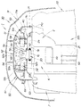
図1は、船外機の全体を示す側面図であり、内部機構の主なものを破線で示した図である。
1は船外機であり、図の右側の矢印Frで示した方向を推進方向の前方とし、左側の矢印Rrで示した方向を後方とし、上部に配置したエンジン2をエンジンカバー30で覆っている。
The best mode for carrying out the present invention will be described below with reference to the accompanying drawings. The drawings are viewed in the direction of the reference numerals.
FIG. 1 is a side view showing the entire outboard motor, and is a diagram showing main components of the internal mechanism in broken lines.
エンジン2は、シリンダ、ピストンが略水平(横向きと記す)で、クランクシャフト略縦向き(縦置きと記す)の4ストローク複数気筒エンジンである。
エンジン2は、後方にシリンダヘッドカバー3bを備え、燃焼室3aを内頂部に有するシリンダヘッド3、シリンダ4a、ピストン4bを備える中間部のシリンダブロック4、クランクシャフト5aを内装した前方のクランクケース5を備える。
クランクケース5とシリンダブロック4とでエンジンブロックを構成する。
The engine 2 is a four-stroke multi-cylinder engine in which a cylinder and a piston are substantially horizontal (referred to as horizontal orientation) and a crankshaft is substantially vertical (referred to as vertical orientation).
The engine 2 includes a
The
エンジン2のクランクケース5の前側方には、吸気箱を構成する吸気サイレンサを含むエンジン吸気装置が配設され、吸気サイレンサ6を介してエンジン吸入口に空気(新気)を導入する。
吸気箱である吸気サイレンサ6の一部の壁面で、後述する発電機の冷却後の排風の吸気口への流れを抑制する壁手段を構成する。
An engine intake device including an intake silencer constituting an intake box is disposed on the front side of the
The wall means for suppressing the flow of exhaust air after cooling of the generator, which will be described later, to the intake port is configured by a part of the wall surface of the
又エンジンの吸気サイレンサ6を設けた側には、エンジンの点火制御、或いは燃料噴射装置の制御を行う電子制御装置等の基盤を有する電装箱7を設け、エンジン2の下部にはマウントケース8aが配設され、マウントケース8aでエンジンを支持し、マウントケース8a下面に結合するオイルケース8b内にオイルパン8cが配設されている。
エンジン2の周りは、エンジンカバー30で覆われており、エンジンカバー30は上下2分割カバーで構成され、上カバー31、下カバー35とからなり、前後のロック機構15,15で上下のカバー21,25は開閉自在に一体化されている。
Also, on the side where the
The engine 2 is covered with an
クランクシャフト5aは前記したように縦向きに配設されており、下端部にフライホイール5bを備えるとともに、下方に垂下された駆動軸9に連結されており、駆動軸9は、下カバー35の下方に延設されたエクステンションケース10内を縦通し、エクステンションケース10の下端部に固着されたギヤケース11内のギヤ伝達機構12に連結されている。
As described above, the
ギヤ伝達機構12は、駆動軸9の動力を、ギヤケース11内において前後方向を向いて配置された水平な被動軸12aに伝え、被動軸12aの後端部はギヤケース11の後部から後方に突出し、後端部にプロペラ13が固着され、エンジン2の動力でプロペラ13を駆動し、一対のドグクラッチで切り換えることで、プロペラの正逆回転を切り換え、前進又は後進の推進力を得る。
尚、図面中14は、船の船尾に船外機を着脱自在に取り付けるスターンブラケットである。
The
In the drawing,
図2は、本発明に係る船外機の上部の縦断側面図、図3は、同縦断正面図、図4は、船外機の平面図、図5は、エンジンカバーを破断して示した平面図、図6は、発電機の回転体カバーを取り外した状態の平面図、図7は、チェーン駆動機構カバーを取り外した平面図、図8は、吸気サイレンサをインレットマニホールド側のスロットル弁装置に組み付ける状態を示す船外機のエンジン部の前面側の斜視図である。
そして図9〜図11は回転体カバー単体を示し、図9は後方から見た斜視図で、図10は前方から見た斜視図、図11は、縦断側面図である。
これらの図面を参照しつつ詳細に説明する。
2 is a vertical side view of the upper part of the outboard motor according to the present invention, FIG. 3 is a front view of the vertical section, FIG. 4 is a plan view of the outboard motor, and FIG. 5 is a cutaway view of the engine cover. FIG. 6 is a plan view of the generator with the rotor cover removed, FIG. 7 is a plan view of the chain drive mechanism cover removed, and FIG. 8 is an intake silencer on the inlet manifold side throttle valve device. It is a perspective view of the front side of the engine part of the outboard motor showing the assembled state.
9 to 11 show the rotating body cover alone, FIG. 9 is a perspective view seen from the rear, FIG. 10 is a perspective view seen from the front, and FIG. 11 is a longitudinal side view.
This will be described in detail with reference to these drawings.
図2において、図の右側は船外機の前方(Fr)であり、左側は後方(Rr)であり、エンジンブロック2は前方からクランクケース5、シリンダブロック4、シリンダヘッド3、シリンダヘッドの後面を覆うシリンダヘッドカバー3bを有する。
エンジン2の上面2aで、シリンダブロック4とクランクケース5の境界部の上方にクランクシャフト5aの上部5bが突出しており、クランクシャフト5aの突出部の下部には駆動スプロケット16が固着されている。
In FIG. 2, the right side of the figure is the front (Fr) of the outboard motor, the left side is the rear (Rr), and the engine block 2 is the
On the
一方、シリンダヘッド3内に縦に設置されたカムシャフト3c(図1参照)のエンジンブロック上面2aから突出させた上端部3dには、被動スプロケット17を固着する。駆動・被動の各スプロケット16,17間にはチェーン18を巻回し、図4及び図7で示したようにチェーン18の両側にスリッパ状のガイド19,19を備えるカムシャフト駆動用のチェーン駆動機構20(チェーン伝動機構)を構成する。
On the other hand, a driven
エンジンブロックの一部を構成するクランクケース5の上部5bであって、前半部5cの上部には、側面視がL形となるように一段低い凹段部5dを形成する。
凹段部5dはクランクシャフトのクランク部が横向き凹部となるので、このクランク部の最上部の部分の肩部上方の部分で形成した。
A
The
即ち、クランクケース5は、クランクシャフト最上位の軸受に対応した小径部をなす後壁部5fと、その軸受直下のクランクウエブの回転に対応し、クランク室の一部を形成する前端壁部5gと、後壁部5fと前端壁部5gとを繋ぐ水平な横壁部5eとを有し、凹段部5dを構成する。
That is, the
以上のエンジン2のエンジンブロック上面2a上に配設されるサイレントチェーン駆動機構20は潤滑を必要とするため、潤滑油は周囲に飛散する虞がある。
そこで、エンジン2の上面2a上において、カムシャフトのチェーン駆動機構20の周囲をチェーン駆動機構ケース又はカバー40(以下に第1カバーと記す)で覆う。
Since the silent
Therefore, on the
第1カバー40は、後部の被動スプロケット17側が後方に開放40aし、開放部40aを前記したシリンダヘッドカバー3bの上部3eに設けたコ字形部3fで後方から塞ぎ、コ字形部3fとの当接部をOリング41でシールした。
The
第1カバー40の後部40bは、スプロケット17が位置するので一段高く設定し、これに続く中間部〜前部を一段低く設定し、前端部40dを下向きに逆L形に垂下し、垂下部は後方の開放部40aを除いて全周に亘り縁部40cとして形成し、前部にはオイルシール42でシールした縦通孔を設け、縦通孔を通してクランクシャフト5aの上部5bがカバー40上に突出する。
第1カバー40の前端部の折曲、垂下された縁部40cは、クランクケース5の凹段部5dの上端部で、エンジンブロック上面2aのこの側の前端部(クランクケースの高い部分の前端部)に当接しており、これによりチェーン駆動機構20を全面的に、密閉するカバーを構成する。
The
The
前記第1カバー40上に突出するクランクシャフト5aの上部5bには、発電機50(交流発電機。ACG)を配設する。発電機50は、クランクシャフトに固着され、内周に磁石51aを固着した回転体51と、鉄心52bにコイル52aを巻き付けた発電用コイル52とからなる。
A generator 50 (alternator generator, ACG) is disposed on the
回転体51の外周には、リコイルスタータ用のフランジ53が固着されており、ACGの回転体51の外周に設けたリコイルスタータ用フランジ53は、クランクケース5の凹段部5dの上方に一部が臨むように径方向外方に膨出している。この膨出部下方の隙間を図2のAとして示した。
A
逆カップ状の回転体51の天井部51bには、図6で示したように回転体内部に外気を取り入れる外気導入部54…を設け、外気導入部54…は放射状に複数個設けるものとする。
以上の回転体51は、図6において時計方向(矢印a方向)に回転し、外気の入り口54aを回転方向に向うように形成し、外気導入部54から回転体51の内部に外気を導入し、内部の発電機の主要部を導入冷却風で冷却する。
As shown in FIG. 6, the
The above
前記した吸気サイレンサ6は、図2、図5、図6、図7に示すようにエンジンカバー30内においてエンジン2の前方部、即ちクランクケース5の前方部分に配設されている。
吸気サイレンサは、図3、図5、図6、図7に示すように、船外機の右舷側に配設されており、図2に示すように、側面視においてエンジン2の前記クランクケース5前半部上部に形成した凹段部5d側(後方)に突出する突出上部6aを有する。
The
The intake silencer is disposed on the starboard side of the outboard motor as shown in FIGS. 3, 5, 6, and 7, and as shown in FIG. 2, the
突出上部6aは、吸気サイレンサ6の後半部6bが後方に突出し、凹段部5d上と凹段部5d上方に臨む回転体51のリコイルスタータ用フランジ53との間の空間Aに臨み、ACG50の前部下方を塞ぐように構成される。
従って、ACG50の冷却後の風は吸気サイレンサ6の突出上部6aで遮蔽され、吸気サイレンサ6及びこの出口である外気導出口に接続されるスロットルボディ(燃焼供給装置)に、ACG50の冷却後の風が直ちに流れることを防止することができる。
The projecting
Therefore, the air after cooling the
吸気箱を構成する吸気サイレンサ6は、図2に示すように、中間部に前方且つ下向きの外気取り入れ用の吸入口6cを備え、下部に外気(新気)の排出口である導出口6d(図8参照)を備える。
吸気サイレンサ6は、導出口6dを介してスロットルボディ21の上流側の吸入口に接続されており(図3、図5、図6、図7及び図8参照)、スロットルボディ21の下流側は、シリンダヘッド3の燃焼室3a(図1参照)に下流部22aを接続したインレットマニホールド22の上流部22bに接続されている。
As shown in FIG. 2, the
The
インレットマニホールド22は、図5、図6、図7で明らかなように、エンジン2の左側を通って後部から前方に延設されている。
吸気サイレンサ6の凹段部5dに重なるように侵入した突出上部6aは、凹段部5dと発電機50の回転体51の下面との間の前方に開放された横向きの空間Aに、双方の向かい合う上下面と隙間をもって嘴のように突出して臨んでいる(図2参照)。
As is apparent from FIGS. 5, 6, and 7, the
The projecting
そして、後述する回転体カバー60(第2カバー)の前部に位置する下流側棚面部67は、吸気サイレンサの突出部6aから、これに連続して前方に延出された吸気サイレンサ6の上面6eの前後方向の中間部まで延出され、吸気サイレンサ6の吸気口6c以外の方向に、発電機50の冷却後の排風の流れを指向させる。
And the downstream
エンジンカバー30の上カバー31は、上面31aの後半部31bに前後方向を向き、後方に開放された凹部32を備え、凹部32の前後方向の中間部に上向きに開口する外気取入口33を備え、外気取入口33は実施例では、図4に示したように平面視略五角形の筒状をなす。
上カバー31の上面31aは、外気取入口33の後方に臨む前半部31cの部分で高くなっていて上方に膨出し、前半部31cの前端部は緩やかに下方に湾曲して傾斜し、前壁部31dに合流し、又上面31aの後端部は後壁31eと合流し、周壁として上面周囲を囲んでいる。
The
The
上面31aの後半部31bに形成した凹部32の上を覆うように蓋であるチルトハンドル又はリッド34を設け、リッド34は脚部34a…で上面31aの後半部31bの外気取入口33の周囲に取り付け、支持されている。
上記リッド34の後端部34bと凹部32との間には、外気取り入れ用の隙間Sが形成され、この隙間Sから外気取入口33を介して、エンジンカバー30内に外気を取り入れる。リッド34と凹部32との間で、エンジンルームの外気取入開口を構成する。
A tilt handle or
A gap S for taking in outside air is formed between the
以上のACG50の回転体51の周囲を回転体カバー60(以下に第2カバーと記す)で覆う。
第2カバー60の単体は図9〜図11に示す通りである。
回転体を覆う第2カバー60は、エンジンカバー30内に取り入れる外気の案内手段、整流及びACG50をエンジンルーム内の環境から保護する機能を有するものである。
The periphery of the
The single unit of the
The
第2カバー60は逆キャップ状の本体61を有し、本体61は円盤状で湾曲屋根状の天蓋部62と、これの下端部周から下方に垂下した周壁部63とを一体に連続して備える。
周壁部63の下端の外縁には、複数の上向きU形の係止部64…や、下向きU形の係止部65を一体に設け、上向きU形係止部64でカム室と吸気サイレンサとを連通するブリーザホースを支持し、下向きU形係止部65はエンジンブロックの凸起(不図示)と係合する貫通孔を有するグロメット65bとともに、第2カバー60をエンジンブロックに固定するためのものである。
The
A plurality of upward
天蓋部62の一部の下端部と周壁部63との間には棚面部66を後方に延設する。
棚面部66は、実施例では平面視が直角三角形類似の板状体で構成され、板状体には後方に開放した複数条の凹凸部66a…を備える。
棚面部66の前端部は天蓋部62に連続し、上方に湾曲した天蓋部62の幅方向中間部の上面62aと連続面を構成し、水平な棚面部56から天蓋部52の上面に棚面部56の上面56aは連続している(図9、図11参照)。
A
In the embodiment, the
The front end portion of the
天蓋部52の外周で、前記した棚面部66の反対側には棚面部67を前方に突設し、この前方に延出した棚面部67を下流側棚面部と記し、前記した後方に延出した棚面部66を上流側棚面部と記した。
棚面部66,67は、上流側棚面部66が前後方向に長く、下流側棚面部67は短く、棚面部67の上面67aは平坦であり、上面67aは天蓋部62に連続し、上方に湾曲した天蓋部62の幅方向中間部の前記した上面62aと連続面を構成する。
この下流側棚面部67、天蓋部62の上面62a、上流側棚面部66で連続したエンジンカバー30内に取り入れら外気(空気)の案内面を構成する。
On the outer periphery of the
The
The downstream
天蓋部62前後の棚面部66,67、天蓋部62の上面の両側部には、側部案内面を構成する板状の案内壁68,69を起立設置する。
案内壁68,69は、一方68は、上流側棚面部66の斜辺部66bの前部で天蓋部62と合流する部分から始まり、この部分から少し立ち上がって立上部68aとし、これの前端部から斜め上方に上傾する斜辺68bとし、この部分から前方に延出して若干前方に緩やかに下傾した壁部前半部68cとし、下流側棚面部67の側部にまで延びて起立して配設される。
Plate-
One of the
他方の案内壁69は、上流側棚面部66の直線状の辺66cから始まる低い上流部69aと、天蓋部上面62aの前端部から直立し、前方に延びる高い壁部69bとを備え、壁部69bは、下流側棚面部67の一側まで設置されている。
以上の左右の案内壁68,69は、左右で形状、高さ、前後方向の長さが非対称である。
The
The left and
以上の案内壁68,69は概ね左右で平行に設けられており、図5で明らかなように、全体として上流側が左側(図5の上方)に少し偏り、下流側が少し右側(図5の下方)に偏っている。
ところで、天蓋部62の左右の案内壁68,69で囲まれた上面62aを除く左右の部分の上面62b,62cには、天蓋部62の中心から放射状に複数の長孔を上下に貫通するように設け、本体61内への空気導入孔70…を形成する。
The
By the way, the upper and
以上の本体61の前後に突設した上流側棚面部66、下流側棚面部67、左右の案内壁68,69、この間の上方に湾曲した天蓋部62の上面62aで吸気案内手段を構成することとなる。
The upstream side
また、本体61の周壁部63の一側部、具体的は左側(図3で紙面表裏方向の手前が船外機の前方なので右側、図5で右側が前方なので上方)には、外方に概ね角形に膨出するダクト部71を設ける。
ダクト部71は左前方から見た様子を示した斜視図である図10、縦断側面図である図11で明示されており、周壁63のこの面の内面63aの前後方向中間部に左外方に膨出するように形成されており、膨出したダクト部71は、上面71a、前後の面71b、71cが閉じ、下方が開放71dされている。
Further, on one side of the
The
これにより、本体61の天蓋部62内と連通し、周壁部63の一部から外方に膨出し、下方に開放部71dでエンジンカバー内(エンジンルーム内)に開放されたダクト部71を本体61の一側部に一体に形成した。
第2カバー60内に冷却風取入部70…からエンジンカバー30内に取り入れられた外気を内部に取り入れ、外気は、発電機50の回転体51の上面に設けた外気導入部54…から発電機50内に導入され、発電機50の発熱部を冷却し、ダクト部71等からエンジンルーム内に排出される。
As a result, the
The outside air taken into the
以上の第2カバー60をエンジンブロックに取り付け、固定した前記した第1カバー40上に突出した発電機50上方に被せ、発電機50を外側から覆う。回転体51を含む外側は、第2カバー60の本体61で覆われ、エンジンカバー30の上カバー31内の中間部〜前半部31cの天井下方に空間を空けて位置する。
上流側棚面部66はエンジンカバー30の上カバー31の後半部に設けた外気取入口33の下方に位置し、案内壁68,69、上流側棚面部66、天蓋部62bの上面62a、下流側棚面部67は、エンジンカバー内の上部において上流側(船外機の後方)から下流側(船外機の前方)に向けて空気案内通路72(図2参照)を形成する。
吸気案内通路72で吸気案内手段による吸気通路を構成する。
The above-described
The
The
第2カバー60の上流側においては、本体61の前部(空気案内通路72の上流側である前部)が、吸気サイレンサ6のクランクケース5前半部上部に形成した凹段部5d側(後方)に突出する突出上部6a上に少しの隙間をもって臨む。
第2カバー60の本体61の前端部の上流側棚面部67は、吸気サイレンサ6の凹段部5d側(後方)に突出する突出上部6aの上方から、上面部6eの中間部の上方にまで少しの隙間をもって位置する(図2参照)。
On the upstream side of the
The upstream side
以上の第2カバー60の本体61の側方に膨出して設けたダクト部71は、図3及び図5に示したように、エンジン2の上方において左側に位置するように設けられており、ダクト部71は、エンジン2の右側に配設される電装品7の設置部位とは反対側に設けられる。
ダクト部71の開放部71dの下方には、エンジンの吸気通路を構成するインレットマニホールド22の上方に位置するように配設する。
The
It arrange | positions so that it may be located under the
第2カバー60内に導入された冷却空気(冷却風)で発電機50は冷却され、冷却後の温風はダクト部71の下方の開放部71dから排出され、制御基盤を有する電装箱7とは反対側に冷却後の温風を排出するので、制御基盤を有する電装箱7への発電機50の冷却後の排風の熱影響を防止することが出来る。
また、第2カバー本体61の前部から吸気サイレンサ6の上面にかけて回転体51の下面及び第2カバー60の本体61の前部に設けた上流側棚面部67が臨み、吸気サイレンサ6の前面部6fにかけて空気案内壁が構成され、吸気サイレンサ6とエンジンのクランクケース5との間への発電機冷却後の温風の流れを可級的に防止する。
The
Further, from the front portion of the
以上の第2カバー60の天蓋部62に設けた本体61内への空気導入孔70…、本体内部の空間、排出部であるダクト71、本体前部の回転体下方に開放され、吸気サイレンサ6の上面と上流側棚面部67の下面とにより、回転体カバーの発電機冷却風通路が構成される。
The
図12は、エンジンカバー内に取り入れた空気の流れを示す説明図であり、構成要素は代表的なものにのみ符号を付した。
外の空気は、エンジンカバー30の上カバー31の後半部に設けたリッド34と凹部32との間の空間S(外気取入口)からリッド34と凹部32との間に矢印(a)のように侵入する。
侵入した空気は、空気取入口33からエンジンカバー内矢印(b)のように侵入し、取入口23の直下の第2カバー60の上流側棚面部66に突き当たる。
FIG. 12 is an explanatory diagram showing the flow of air taken into the engine cover, and constituent elements are only given reference numerals.
The outside air is indicated by an arrow (a) between the
The intruded air enters from the
上流側棚面部66に当たった空気は矢印(c)方向に流れ、左右の案内壁68,69で規制され、上流側棚面部66、天蓋部62の上面62a、下流側棚面部67等で構成される空気案内通路72に案内され、エンジンカバーの上カバー31の天井面31fに沿って湾曲内面31gに案内され、下方に向かう前壁内面31hに流れ、吸気サイレンサ6の吸気口6cに新気として吸引される。
The air hitting the
このようにエンジンで吸引すべき空気は、矢印(d)のように整流されて流れる。
この空気流は、エンジンカバーの上カバー31の前端部内に湾曲コーナー部に案内され、前面部の内壁に沿って前述のように下方に流れる。
この先に、吸気装置を構成する吸気サイレンサ6が臨み、吸気サイレンサ6の下向き吸入口6cから空気は吸入され、燃料供給装置であるスロットルボディ内に新気として供給される。
In this way, the air to be sucked by the engine flows while being rectified as indicated by an arrow (d).
This air flow is guided to the curved corner portion in the front end portion of the
First, the
ところで、エンジンカバー内に取り入れられた空気は、前記した矢印(a)、(b)、(c)、(d)のように流れるが、外気取入口33下方において、棚面部66の後方が開放されていることと、左右の案内壁68,69が左右非対称なので、天蓋部62の左右の上面にも流れる。
ところで、本体61内で発電機50の回転体51は回転しており、回転体51の上面に設けた空気導入ガイド部54…の作用で、天蓋部62に設けた空気導入孔70…から、天蓋部62の左右の上面の流れから空気を発電機50の内部に吸入する。
By the way, the air taken into the engine cover flows as indicated by the arrows (a), (b), (c), and (d), but the rear side of the
By the way, the rotating
天蓋部62に設けた空気導入孔70…から吸入された外気は、回転体51の空気導入ガイド部54…を通して発電機50内に導入され、発電コイル等の発熱源を冷却する。
冷却後の温風からなる排風は、一部が第2カバー60の側方のダクト部71から下方のインレットマニホールド22に上から放出される。
The outside air sucked from the air introduction holes 70 provided in the
A part of the exhaust air composed of warm air after cooling is discharged from above from the
発電機50冷却後の排風で、前部から排出される排風は、吸気サイレンサ6の前記した凹段部5dを塞ぐ突出上部6aと回転体51の前部の下方、吸気サイレンサ6の上面6e、第2カバー60の下流側棚面部67の間の隙間Aを矢印(e)のように通り、矢印(d)の流れに合流して吸気サイレンサ6の前部外壁面6hの外面を流れ、新気と合流して冷却され、矢印(d)の通りエンジンカバー前部内壁面31hに流れる。
従って、発電機の冷却後の流れ(e)による排風は、直接吸気サイレンサ6の吸気口、即ち、エンジン吸気口にそのまま到達することはない。
Exhaust air exhausted from the front part of the exhaust air after cooling the
Therefore, the exhaust air generated by the flow (e) after cooling the generator does not directly reach the intake port of the
そして、空気案内通路72の下流方向に流れる空気(矢印(c))は、下流側棚面部67の上面を通って吸気サイレンサ6と上カバー31の前壁内面との間を通り、下方に案内され、吸気サイレンサ6の吸入口6cから吸入される。
The air flowing in the downstream direction of the air guide passage 72 (arrow (c)) passes between the
本発明に係る船外機は、船外機に付設した発電機の冷却に好適である。 The outboard motor according to the present invention is suitable for cooling a generator attached to the outboard motor.
1…船外機、 2…エンジン、 3a…燃焼室、 4,5…エンジンブロック、 5a…クランクシャフト、 5d…凹段部、 6…吸気箱である吸気サイレンサ、 6a…壁手段である突出部、 6c…エンジン吸気口、 21…スロットル弁、 33…外気取入口、 30…エンジンカバー、 50…発電機、 51…回転体、 60…発電機カバー、 67…発電機カバーの覆う部分。
DESCRIPTION OF
Claims (3)
前記クランクシャフトの上部に設けられ、前記外気取入口と前記エンジンの吸気口との間に回転体を含む発電機を設け、
前記発電機の回転体と前記エンジンブロックとの間に壁手段を設け、
前記エンジンの吸気口は、スロットル弁より上流の吸気箱に設けられており、前記壁手段は前記吸気箱の前記吸気口が形成されていない壁面以外の壁面で構成し、
前記吸気箱の一部が前記発電機の回転体と前記エンジンブロックの上面との間に介在し、前記吸気口はこの介在部分以外の部分に設けられている、
ことを特徴とする船外機。 A generally vertical crankshaft, an engine block that accommodates the crankshaft, an engine that includes an intake port for the combustion chamber of the engine, and an engine cover that forms a space for accommodating the engine and has an outside air intake An outboard motor
Provided at the upper part of the crankshaft, a generator including a rotating body is provided between the outside air intake and the engine intake port,
Providing wall means between the rotating body of the generator and the engine block;
The intake port of the engine is provided in an intake box upstream of the throttle valve, and the wall means is constituted by a wall surface other than a wall surface where the intake port of the intake box is not formed,
A part of the intake box is interposed between the rotating body of the generator and the upper surface of the engine block, and the intake port is provided in a part other than the interposed part.
Outboard motor characterized by that.
Priority Applications (2)
| Application Number | Priority Date | Filing Date | Title |
|---|---|---|---|
| JP2006097564A JP4719609B2 (en) | 2006-03-31 | 2006-03-31 | Outboard motor |
| US11/730,261 US7421997B2 (en) | 2006-03-31 | 2007-03-30 | Outboard engine unit |
Applications Claiming Priority (1)
| Application Number | Priority Date | Filing Date | Title |
|---|---|---|---|
| JP2006097564A JP4719609B2 (en) | 2006-03-31 | 2006-03-31 | Outboard motor |
Publications (2)
| Publication Number | Publication Date |
|---|---|
| JP2007269185A JP2007269185A (en) | 2007-10-18 |
| JP4719609B2 true JP4719609B2 (en) | 2011-07-06 |
Family
ID=38672415
Family Applications (1)
| Application Number | Title | Priority Date | Filing Date |
|---|---|---|---|
| JP2006097564A Expired - Fee Related JP4719609B2 (en) | 2006-03-31 | 2006-03-31 | Outboard motor |
Country Status (1)
| Country | Link |
|---|---|
| JP (1) | JP4719609B2 (en) |
Cited By (1)
| Publication number | Priority date | Publication date | Assignee | Title |
|---|---|---|---|---|
| JP7324148B2 (en) | 2018-02-07 | 2023-08-09 | ダイキン工業株式会社 | Method for producing composition containing low-molecular-weight polytetrafluoroethylene |
Families Citing this family (2)
| Publication number | Priority date | Publication date | Assignee | Title |
|---|---|---|---|---|
| JP5759817B2 (en) * | 2011-07-23 | 2015-08-05 | 本田技研工業株式会社 | Outboard motor |
| EP3643745B1 (en) * | 2016-08-04 | 2024-09-18 | Daikin Industries, Ltd. | Powder comprising low molecular weight polytetrafluoroethylene and uses thereof |
Citations (4)
| Publication number | Priority date | Publication date | Assignee | Title |
|---|---|---|---|---|
| JPH0777059A (en) * | 1993-09-08 | 1995-03-20 | Sanshin Ind Co Ltd | Intake device of engine for outboard motor |
| JPH08100647A (en) * | 1994-09-30 | 1996-04-16 | Honda Motor Co Ltd | Cover structure for rotational body of vertical engine and hand starting pulley housed in cover |
| JPH0949435A (en) * | 1995-08-07 | 1997-02-18 | Sanshin Ind Co Ltd | Four-cycle engine for outboard engine |
| JP2001263062A (en) * | 2000-03-16 | 2001-09-26 | Sanshin Ind Co Ltd | Cooling structure of outboard motor |
-
2006
- 2006-03-31 JP JP2006097564A patent/JP4719609B2/en not_active Expired - Fee Related
Patent Citations (4)
| Publication number | Priority date | Publication date | Assignee | Title |
|---|---|---|---|---|
| JPH0777059A (en) * | 1993-09-08 | 1995-03-20 | Sanshin Ind Co Ltd | Intake device of engine for outboard motor |
| JPH08100647A (en) * | 1994-09-30 | 1996-04-16 | Honda Motor Co Ltd | Cover structure for rotational body of vertical engine and hand starting pulley housed in cover |
| JPH0949435A (en) * | 1995-08-07 | 1997-02-18 | Sanshin Ind Co Ltd | Four-cycle engine for outboard engine |
| JP2001263062A (en) * | 2000-03-16 | 2001-09-26 | Sanshin Ind Co Ltd | Cooling structure of outboard motor |
Cited By (1)
| Publication number | Priority date | Publication date | Assignee | Title |
|---|---|---|---|---|
| JP7324148B2 (en) | 2018-02-07 | 2023-08-09 | ダイキン工業株式会社 | Method for producing composition containing low-molecular-weight polytetrafluoroethylene |
Also Published As
| Publication number | Publication date |
|---|---|
| JP2007269185A (en) | 2007-10-18 |
Similar Documents
| Publication | Publication Date | Title |
|---|---|---|
| US6964255B2 (en) | Outboard motor | |
| JP4052528B2 (en) | Outboard motor | |
| JP4913118B2 (en) | Outboard motor | |
| KR100782426B1 (en) | Air-cooling type internal combustion engine comprising sensors for detecting engine conditions | |
| JP2007296997A (en) | Outboard motor | |
| JPH0949435A (en) | Four-cycle engine for outboard engine | |
| JP4719609B2 (en) | Outboard motor | |
| JP3698800B2 (en) | Water vehicle engine mounting structure | |
| JP2007321642A (en) | Outboard motor | |
| JPH0616187A (en) | Outboard motor | |
| JP4726676B2 (en) | Outboard motor | |
| JPH10176517A (en) | Engine for outboard engine | |
| JP4629247B2 (en) | Outboard motor cooling passage structure | |
| JP4699937B2 (en) | Outboard motor | |
| JP2010058770A (en) | Outboard motor | |
| JP3906645B2 (en) | Engine auxiliary cooling system | |
| JP2000001198A (en) | Suction system for outboard motor | |
| JP4719607B2 (en) | Outboard motor | |
| JP2007177679A (en) | Air cooling internal combustion engine provided with oil temperature sensor | |
| JP4719608B2 (en) | Outboard motor | |
| JP2002070573A (en) | Outboard motor | |
| JP2000118496A (en) | Outboard motor | |
| JP4937150B2 (en) | Internal combustion engine | |
| JPH11198893A (en) | Outboard motor | |
| JP2001123847A (en) | Four-cycle engine for small-sized ship |
Legal Events
| Date | Code | Title | Description |
|---|---|---|---|
| A621 | Written request for application examination |
Free format text: JAPANESE INTERMEDIATE CODE: A621 Effective date: 20081126 |
|
| A977 | Report on retrieval |
Free format text: JAPANESE INTERMEDIATE CODE: A971007 Effective date: 20100824 |
|
| A131 | Notification of reasons for refusal |
Free format text: JAPANESE INTERMEDIATE CODE: A131 Effective date: 20100831 |
|
| A521 | Request for written amendment filed |
Free format text: JAPANESE INTERMEDIATE CODE: A523 Effective date: 20101008 |
|
| TRDD | Decision of grant or rejection written | ||
| A01 | Written decision to grant a patent or to grant a registration (utility model) |
Free format text: JAPANESE INTERMEDIATE CODE: A01 Effective date: 20110329 |
|
| A01 | Written decision to grant a patent or to grant a registration (utility model) |
Free format text: JAPANESE INTERMEDIATE CODE: A01 |
|
| A61 | First payment of annual fees (during grant procedure) |
Free format text: JAPANESE INTERMEDIATE CODE: A61 Effective date: 20110404 |
|
| R150 | Certificate of patent or registration of utility model |
Ref document number: 4719609 Country of ref document: JP Free format text: JAPANESE INTERMEDIATE CODE: R150 Free format text: JAPANESE INTERMEDIATE CODE: R150 |
|
| FPAY | Renewal fee payment (event date is renewal date of database) |
Free format text: PAYMENT UNTIL: 20140408 Year of fee payment: 3 |
|
| LAPS | Cancellation because of no payment of annual fees |