JP4703084B2 - Spinal therapy device - Google Patents
Spinal therapy device Download PDFInfo
- Publication number
- JP4703084B2 JP4703084B2 JP2001559335A JP2001559335A JP4703084B2 JP 4703084 B2 JP4703084 B2 JP 4703084B2 JP 2001559335 A JP2001559335 A JP 2001559335A JP 2001559335 A JP2001559335 A JP 2001559335A JP 4703084 B2 JP4703084 B2 JP 4703084B2
- Authority
- JP
- Japan
- Prior art keywords
- disc
- hole
- spinal
- anterior
- posterior
- Prior art date
- Legal status (The legal status is an assumption and is not a legal conclusion. Google has not performed a legal analysis and makes no representation as to the accuracy of the status listed.)
- Expired - Fee Related
Links
Images


Classifications
-
- A—HUMAN NECESSITIES
- A61—MEDICAL OR VETERINARY SCIENCE; HYGIENE
- A61B—DIAGNOSIS; SURGERY; IDENTIFICATION
- A61B17/00—Surgical instruments, devices or methods
- A61B17/56—Surgical instruments or methods for treatment of bones or joints; Devices specially adapted therefor
- A61B17/58—Surgical instruments or methods for treatment of bones or joints; Devices specially adapted therefor for osteosynthesis, e.g. bone plates, screws or setting implements
- A61B17/68—Internal fixation devices, including fasteners and spinal fixators, even if a part thereof projects from the skin
- A61B17/70—Spinal positioners or stabilisers, e.g. stabilisers comprising fluid filler in an implant
- A61B17/7097—Stabilisers comprising fluid filler in an implant, e.g. balloon; devices for inserting or filling such implants
-
- A—HUMAN NECESSITIES
- A61—MEDICAL OR VETERINARY SCIENCE; HYGIENE
- A61B—DIAGNOSIS; SURGERY; IDENTIFICATION
- A61B17/00—Surgical instruments, devices or methods
- A61B17/16—Instruments for performing osteoclasis; Drills or chisels for bones; Trepans
- A61B17/1662—Instruments for performing osteoclasis; Drills or chisels for bones; Trepans for particular parts of the body
- A61B17/1671—Instruments for performing osteoclasis; Drills or chisels for bones; Trepans for particular parts of the body for the spine
-
- A—HUMAN NECESSITIES
- A61—MEDICAL OR VETERINARY SCIENCE; HYGIENE
- A61B—DIAGNOSIS; SURGERY; IDENTIFICATION
- A61B17/00—Surgical instruments, devices or methods
- A61B17/16—Instruments for performing osteoclasis; Drills or chisels for bones; Trepans
- A61B17/17—Guides or aligning means for drills, mills, pins or wires
- A61B17/1739—Guides or aligning means for drills, mills, pins or wires specially adapted for particular parts of the body
- A61B17/1757—Guides or aligning means for drills, mills, pins or wires specially adapted for particular parts of the body for the spine
-
- A—HUMAN NECESSITIES
- A61—MEDICAL OR VETERINARY SCIENCE; HYGIENE
- A61B—DIAGNOSIS; SURGERY; IDENTIFICATION
- A61B17/00—Surgical instruments, devices or methods
- A61B17/32—Surgical cutting instruments
- A61B17/320016—Endoscopic cutting instruments, e.g. arthroscopes, resectoscopes
- A61B17/32002—Endoscopic cutting instruments, e.g. arthroscopes, resectoscopes with continuously rotating, oscillating or reciprocating cutting instruments
-
- A—HUMAN NECESSITIES
- A61—MEDICAL OR VETERINARY SCIENCE; HYGIENE
- A61B—DIAGNOSIS; SURGERY; IDENTIFICATION
- A61B17/00—Surgical instruments, devices or methods
- A61B17/56—Surgical instruments or methods for treatment of bones or joints; Devices specially adapted therefor
- A61B17/58—Surgical instruments or methods for treatment of bones or joints; Devices specially adapted therefor for osteosynthesis, e.g. bone plates, screws or setting implements
- A61B17/68—Internal fixation devices, including fasteners and spinal fixators, even if a part thereof projects from the skin
- A61B17/70—Spinal positioners or stabilisers, e.g. stabilisers comprising fluid filler in an implant
- A61B17/7061—Spinal positioners or stabilisers, e.g. stabilisers comprising fluid filler in an implant for stabilising vertebrae or discs by improving the condition of their tissues, e.g. using implanted medication or fluid exchange
-
- A—HUMAN NECESSITIES
- A61—MEDICAL OR VETERINARY SCIENCE; HYGIENE
- A61B—DIAGNOSIS; SURGERY; IDENTIFICATION
- A61B17/00—Surgical instruments, devices or methods
- A61B17/56—Surgical instruments or methods for treatment of bones or joints; Devices specially adapted therefor
- A61B17/58—Surgical instruments or methods for treatment of bones or joints; Devices specially adapted therefor for osteosynthesis, e.g. bone plates, screws or setting implements
- A61B17/68—Internal fixation devices, including fasteners and spinal fixators, even if a part thereof projects from the skin
- A61B17/70—Spinal positioners or stabilisers, e.g. stabilisers comprising fluid filler in an implant
- A61B17/7097—Stabilisers comprising fluid filler in an implant, e.g. balloon; devices for inserting or filling such implants
- A61B17/7098—Stabilisers comprising fluid filler in an implant, e.g. balloon; devices for inserting or filling such implants wherein the implant is permeable or has openings, e.g. fenestrated screw
-
- A—HUMAN NECESSITIES
- A61—MEDICAL OR VETERINARY SCIENCE; HYGIENE
- A61B—DIAGNOSIS; SURGERY; IDENTIFICATION
- A61B17/00—Surgical instruments, devices or methods
- A61B17/56—Surgical instruments or methods for treatment of bones or joints; Devices specially adapted therefor
- A61B17/58—Surgical instruments or methods for treatment of bones or joints; Devices specially adapted therefor for osteosynthesis, e.g. bone plates, screws or setting implements
- A61B17/88—Osteosynthesis instruments; Methods or means for implanting or extracting internal or external fixation devices
- A61B17/8802—Equipment for handling bone cement or other fluid fillers
- A61B17/8805—Equipment for handling bone cement or other fluid fillers for introducing fluid filler into bone or extracting it
- A61B17/8811—Equipment for handling bone cement or other fluid fillers for introducing fluid filler into bone or extracting it characterised by the introducer tip, i.e. the part inserted into or onto the bone
-
- A—HUMAN NECESSITIES
- A61—MEDICAL OR VETERINARY SCIENCE; HYGIENE
- A61B—DIAGNOSIS; SURGERY; IDENTIFICATION
- A61B17/00—Surgical instruments, devices or methods
- A61B17/56—Surgical instruments or methods for treatment of bones or joints; Devices specially adapted therefor
- A61B17/58—Surgical instruments or methods for treatment of bones or joints; Devices specially adapted therefor for osteosynthesis, e.g. bone plates, screws or setting implements
- A61B17/88—Osteosynthesis instruments; Methods or means for implanting or extracting internal or external fixation devices
- A61B17/8802—Equipment for handling bone cement or other fluid fillers
- A61B17/8805—Equipment for handling bone cement or other fluid fillers for introducing fluid filler into bone or extracting it
- A61B17/8819—Equipment for handling bone cement or other fluid fillers for introducing fluid filler into bone or extracting it characterised by the introducer proximal part, e.g. cannula handle, or by parts which are inserted inside each other, e.g. stylet and cannula
-
- A—HUMAN NECESSITIES
- A61—MEDICAL OR VETERINARY SCIENCE; HYGIENE
- A61F—FILTERS IMPLANTABLE INTO BLOOD VESSELS; PROSTHESES; DEVICES PROVIDING PATENCY TO, OR PREVENTING COLLAPSING OF, TUBULAR STRUCTURES OF THE BODY, e.g. STENTS; ORTHOPAEDIC, NURSING OR CONTRACEPTIVE DEVICES; FOMENTATION; TREATMENT OR PROTECTION OF EYES OR EARS; BANDAGES, DRESSINGS OR ABSORBENT PADS; FIRST-AID KITS
- A61F2/00—Filters implantable into blood vessels; Prostheses, i.e. artificial substitutes or replacements for parts of the body; Appliances for connecting them with the body; Devices providing patency to, or preventing collapsing of, tubular structures of the body, e.g. stents
- A61F2/02—Prostheses implantable into the body
- A61F2/30—Joints
- A61F2/44—Joints for the spine, e.g. vertebrae, spinal discs
- A61F2/441—Joints for the spine, e.g. vertebrae, spinal discs made of inflatable pockets or chambers filled with fluid, e.g. with hydrogel
-
- A—HUMAN NECESSITIES
- A61—MEDICAL OR VETERINARY SCIENCE; HYGIENE
- A61F—FILTERS IMPLANTABLE INTO BLOOD VESSELS; PROSTHESES; DEVICES PROVIDING PATENCY TO, OR PREVENTING COLLAPSING OF, TUBULAR STRUCTURES OF THE BODY, e.g. STENTS; ORTHOPAEDIC, NURSING OR CONTRACEPTIVE DEVICES; FOMENTATION; TREATMENT OR PROTECTION OF EYES OR EARS; BANDAGES, DRESSINGS OR ABSORBENT PADS; FIRST-AID KITS
- A61F2/00—Filters implantable into blood vessels; Prostheses, i.e. artificial substitutes or replacements for parts of the body; Appliances for connecting them with the body; Devices providing patency to, or preventing collapsing of, tubular structures of the body, e.g. stents
- A61F2/02—Prostheses implantable into the body
- A61F2/30—Joints
- A61F2/44—Joints for the spine, e.g. vertebrae, spinal discs
- A61F2/4455—Joints for the spine, e.g. vertebrae, spinal discs for the fusion of spinal bodies, e.g. intervertebral fusion of adjacent spinal bodies, e.g. fusion cages
- A61F2/4465—Joints for the spine, e.g. vertebrae, spinal discs for the fusion of spinal bodies, e.g. intervertebral fusion of adjacent spinal bodies, e.g. fusion cages having a circular or kidney shaped cross-section substantially perpendicular to the axis of the spine
-
- A—HUMAN NECESSITIES
- A61—MEDICAL OR VETERINARY SCIENCE; HYGIENE
- A61F—FILTERS IMPLANTABLE INTO BLOOD VESSELS; PROSTHESES; DEVICES PROVIDING PATENCY TO, OR PREVENTING COLLAPSING OF, TUBULAR STRUCTURES OF THE BODY, e.g. STENTS; ORTHOPAEDIC, NURSING OR CONTRACEPTIVE DEVICES; FOMENTATION; TREATMENT OR PROTECTION OF EYES OR EARS; BANDAGES, DRESSINGS OR ABSORBENT PADS; FIRST-AID KITS
- A61F2/00—Filters implantable into blood vessels; Prostheses, i.e. artificial substitutes or replacements for parts of the body; Appliances for connecting them with the body; Devices providing patency to, or preventing collapsing of, tubular structures of the body, e.g. stents
- A61F2/02—Prostheses implantable into the body
- A61F2/30—Joints
- A61F2/46—Special tools for implanting artificial joints
- A61F2/4601—Special tools for implanting artificial joints for introducing bone substitute, for implanting bone graft implants or for compacting them in the bone cavity
-
- A—HUMAN NECESSITIES
- A61—MEDICAL OR VETERINARY SCIENCE; HYGIENE
- A61F—FILTERS IMPLANTABLE INTO BLOOD VESSELS; PROSTHESES; DEVICES PROVIDING PATENCY TO, OR PREVENTING COLLAPSING OF, TUBULAR STRUCTURES OF THE BODY, e.g. STENTS; ORTHOPAEDIC, NURSING OR CONTRACEPTIVE DEVICES; FOMENTATION; TREATMENT OR PROTECTION OF EYES OR EARS; BANDAGES, DRESSINGS OR ABSORBENT PADS; FIRST-AID KITS
- A61F2/00—Filters implantable into blood vessels; Prostheses, i.e. artificial substitutes or replacements for parts of the body; Appliances for connecting them with the body; Devices providing patency to, or preventing collapsing of, tubular structures of the body, e.g. stents
- A61F2/02—Prostheses implantable into the body
- A61F2/30—Joints
- A61F2/46—Special tools for implanting artificial joints
- A61F2/4603—Special tools for implanting artificial joints for insertion or extraction of endoprosthetic joints or of accessories thereof
- A61F2/4611—Special tools for implanting artificial joints for insertion or extraction of endoprosthetic joints or of accessories thereof of spinal prostheses
-
- A—HUMAN NECESSITIES
- A61—MEDICAL OR VETERINARY SCIENCE; HYGIENE
- A61B—DIAGNOSIS; SURGERY; IDENTIFICATION
- A61B17/00—Surgical instruments, devices or methods
- A61B17/32—Surgical cutting instruments
- A61B17/3205—Excision instruments
- A61B17/3207—Atherectomy devices working by cutting or abrading; Similar devices specially adapted for non-vascular obstructions
- A61B17/320725—Atherectomy devices working by cutting or abrading; Similar devices specially adapted for non-vascular obstructions with radially expandable cutting or abrading elements
-
- A—HUMAN NECESSITIES
- A61—MEDICAL OR VETERINARY SCIENCE; HYGIENE
- A61B—DIAGNOSIS; SURGERY; IDENTIFICATION
- A61B17/00—Surgical instruments, devices or methods
- A61B17/56—Surgical instruments or methods for treatment of bones or joints; Devices specially adapted therefor
- A61B17/58—Surgical instruments or methods for treatment of bones or joints; Devices specially adapted therefor for osteosynthesis, e.g. bone plates, screws or setting implements
- A61B17/68—Internal fixation devices, including fasteners and spinal fixators, even if a part thereof projects from the skin
- A61B17/70—Spinal positioners or stabilisers, e.g. stabilisers comprising fluid filler in an implant
- A61B17/7055—Spinal positioners or stabilisers, e.g. stabilisers comprising fluid filler in an implant connected to sacrum, pelvis or skull
-
- A—HUMAN NECESSITIES
- A61—MEDICAL OR VETERINARY SCIENCE; HYGIENE
- A61B—DIAGNOSIS; SURGERY; IDENTIFICATION
- A61B17/00—Surgical instruments, devices or methods
- A61B17/00234—Surgical instruments, devices or methods for minimally invasive surgery
- A61B2017/00238—Type of minimally invasive operation
- A61B2017/00261—Discectomy
-
- A—HUMAN NECESSITIES
- A61—MEDICAL OR VETERINARY SCIENCE; HYGIENE
- A61B—DIAGNOSIS; SURGERY; IDENTIFICATION
- A61B17/00—Surgical instruments, devices or methods
- A61B2017/00535—Surgical instruments, devices or methods pneumatically or hydraulically operated
- A61B2017/00557—Surgical instruments, devices or methods pneumatically or hydraulically operated inflatable
-
- A—HUMAN NECESSITIES
- A61—MEDICAL OR VETERINARY SCIENCE; HYGIENE
- A61B—DIAGNOSIS; SURGERY; IDENTIFICATION
- A61B17/00—Surgical instruments, devices or methods
- A61B2017/00681—Aspects not otherwise provided for
- A61B2017/00734—Aspects not otherwise provided for battery operated
-
- A—HUMAN NECESSITIES
- A61—MEDICAL OR VETERINARY SCIENCE; HYGIENE
- A61B—DIAGNOSIS; SURGERY; IDENTIFICATION
- A61B17/00—Surgical instruments, devices or methods
- A61B2017/00831—Material properties
- A61B2017/00867—Material properties shape memory effect
-
- A—HUMAN NECESSITIES
- A61—MEDICAL OR VETERINARY SCIENCE; HYGIENE
- A61B—DIAGNOSIS; SURGERY; IDENTIFICATION
- A61B17/00—Surgical instruments, devices or methods
- A61B17/28—Surgical forceps
- A61B17/29—Forceps for use in minimally invasive surgery
- A61B2017/2901—Details of shaft
- A61B2017/2905—Details of shaft flexible
-
- A—HUMAN NECESSITIES
- A61—MEDICAL OR VETERINARY SCIENCE; HYGIENE
- A61B—DIAGNOSIS; SURGERY; IDENTIFICATION
- A61B17/00—Surgical instruments, devices or methods
- A61B17/32—Surgical cutting instruments
- A61B17/3205—Excision instruments
- A61B17/3207—Atherectomy devices working by cutting or abrading; Similar devices specially adapted for non-vascular obstructions
- A61B2017/320733—Atherectomy devices working by cutting or abrading; Similar devices specially adapted for non-vascular obstructions with a flexible cutting or scraping element, e.g. with a whip-like distal filament member
-
- A—HUMAN NECESSITIES
- A61—MEDICAL OR VETERINARY SCIENCE; HYGIENE
- A61F—FILTERS IMPLANTABLE INTO BLOOD VESSELS; PROSTHESES; DEVICES PROVIDING PATENCY TO, OR PREVENTING COLLAPSING OF, TUBULAR STRUCTURES OF THE BODY, e.g. STENTS; ORTHOPAEDIC, NURSING OR CONTRACEPTIVE DEVICES; FOMENTATION; TREATMENT OR PROTECTION OF EYES OR EARS; BANDAGES, DRESSINGS OR ABSORBENT PADS; FIRST-AID KITS
- A61F2/00—Filters implantable into blood vessels; Prostheses, i.e. artificial substitutes or replacements for parts of the body; Appliances for connecting them with the body; Devices providing patency to, or preventing collapsing of, tubular structures of the body, e.g. stents
- A61F2/02—Prostheses implantable into the body
- A61F2/30—Joints
- A61F2/30721—Accessories
- A61F2/30723—Plugs or restrictors for sealing a cement-receiving space
-
- A—HUMAN NECESSITIES
- A61—MEDICAL OR VETERINARY SCIENCE; HYGIENE
- A61F—FILTERS IMPLANTABLE INTO BLOOD VESSELS; PROSTHESES; DEVICES PROVIDING PATENCY TO, OR PREVENTING COLLAPSING OF, TUBULAR STRUCTURES OF THE BODY, e.g. STENTS; ORTHOPAEDIC, NURSING OR CONTRACEPTIVE DEVICES; FOMENTATION; TREATMENT OR PROTECTION OF EYES OR EARS; BANDAGES, DRESSINGS OR ABSORBENT PADS; FIRST-AID KITS
- A61F2/00—Filters implantable into blood vessels; Prostheses, i.e. artificial substitutes or replacements for parts of the body; Appliances for connecting them with the body; Devices providing patency to, or preventing collapsing of, tubular structures of the body, e.g. stents
- A61F2/02—Prostheses implantable into the body
- A61F2/30—Joints
- A61F2/44—Joints for the spine, e.g. vertebrae, spinal discs
- A61F2/442—Intervertebral or spinal discs, e.g. resilient
-
- A—HUMAN NECESSITIES
- A61—MEDICAL OR VETERINARY SCIENCE; HYGIENE
- A61F—FILTERS IMPLANTABLE INTO BLOOD VESSELS; PROSTHESES; DEVICES PROVIDING PATENCY TO, OR PREVENTING COLLAPSING OF, TUBULAR STRUCTURES OF THE BODY, e.g. STENTS; ORTHOPAEDIC, NURSING OR CONTRACEPTIVE DEVICES; FOMENTATION; TREATMENT OR PROTECTION OF EYES OR EARS; BANDAGES, DRESSINGS OR ABSORBENT PADS; FIRST-AID KITS
- A61F2/00—Filters implantable into blood vessels; Prostheses, i.e. artificial substitutes or replacements for parts of the body; Appliances for connecting them with the body; Devices providing patency to, or preventing collapsing of, tubular structures of the body, e.g. stents
- A61F2/02—Prostheses implantable into the body
- A61F2/30—Joints
- A61F2/44—Joints for the spine, e.g. vertebrae, spinal discs
- A61F2/4455—Joints for the spine, e.g. vertebrae, spinal discs for the fusion of spinal bodies, e.g. intervertebral fusion of adjacent spinal bodies, e.g. fusion cages
-
- A—HUMAN NECESSITIES
- A61—MEDICAL OR VETERINARY SCIENCE; HYGIENE
- A61F—FILTERS IMPLANTABLE INTO BLOOD VESSELS; PROSTHESES; DEVICES PROVIDING PATENCY TO, OR PREVENTING COLLAPSING OF, TUBULAR STRUCTURES OF THE BODY, e.g. STENTS; ORTHOPAEDIC, NURSING OR CONTRACEPTIVE DEVICES; FOMENTATION; TREATMENT OR PROTECTION OF EYES OR EARS; BANDAGES, DRESSINGS OR ABSORBENT PADS; FIRST-AID KITS
- A61F2/00—Filters implantable into blood vessels; Prostheses, i.e. artificial substitutes or replacements for parts of the body; Appliances for connecting them with the body; Devices providing patency to, or preventing collapsing of, tubular structures of the body, e.g. stents
- A61F2/02—Prostheses implantable into the body
- A61F2/28—Bones
- A61F2002/2821—Bone stimulation by electromagnetic fields or electric current for enhancing ossification
-
- A—HUMAN NECESSITIES
- A61—MEDICAL OR VETERINARY SCIENCE; HYGIENE
- A61F—FILTERS IMPLANTABLE INTO BLOOD VESSELS; PROSTHESES; DEVICES PROVIDING PATENCY TO, OR PREVENTING COLLAPSING OF, TUBULAR STRUCTURES OF THE BODY, e.g. STENTS; ORTHOPAEDIC, NURSING OR CONTRACEPTIVE DEVICES; FOMENTATION; TREATMENT OR PROTECTION OF EYES OR EARS; BANDAGES, DRESSINGS OR ABSORBENT PADS; FIRST-AID KITS
- A61F2/00—Filters implantable into blood vessels; Prostheses, i.e. artificial substitutes or replacements for parts of the body; Appliances for connecting them with the body; Devices providing patency to, or preventing collapsing of, tubular structures of the body, e.g. stents
- A61F2/02—Prostheses implantable into the body
- A61F2/28—Bones
- A61F2002/2835—Bone graft implants for filling a bony defect or an endoprosthesis cavity, e.g. by synthetic material or biological material
-
- A—HUMAN NECESSITIES
- A61—MEDICAL OR VETERINARY SCIENCE; HYGIENE
- A61F—FILTERS IMPLANTABLE INTO BLOOD VESSELS; PROSTHESES; DEVICES PROVIDING PATENCY TO, OR PREVENTING COLLAPSING OF, TUBULAR STRUCTURES OF THE BODY, e.g. STENTS; ORTHOPAEDIC, NURSING OR CONTRACEPTIVE DEVICES; FOMENTATION; TREATMENT OR PROTECTION OF EYES OR EARS; BANDAGES, DRESSINGS OR ABSORBENT PADS; FIRST-AID KITS
- A61F2/00—Filters implantable into blood vessels; Prostheses, i.e. artificial substitutes or replacements for parts of the body; Appliances for connecting them with the body; Devices providing patency to, or preventing collapsing of, tubular structures of the body, e.g. stents
- A61F2/02—Prostheses implantable into the body
- A61F2/30—Joints
- A61F2002/30001—Additional features of subject-matter classified in A61F2/28, A61F2/30 and subgroups thereof
- A61F2002/30003—Material related properties of the prosthesis or of a coating on the prosthesis
- A61F2002/3006—Properties of materials and coating materials
- A61F2002/30092—Properties of materials and coating materials using shape memory or superelastic materials, e.g. nitinol
-
- A—HUMAN NECESSITIES
- A61—MEDICAL OR VETERINARY SCIENCE; HYGIENE
- A61F—FILTERS IMPLANTABLE INTO BLOOD VESSELS; PROSTHESES; DEVICES PROVIDING PATENCY TO, OR PREVENTING COLLAPSING OF, TUBULAR STRUCTURES OF THE BODY, e.g. STENTS; ORTHOPAEDIC, NURSING OR CONTRACEPTIVE DEVICES; FOMENTATION; TREATMENT OR PROTECTION OF EYES OR EARS; BANDAGES, DRESSINGS OR ABSORBENT PADS; FIRST-AID KITS
- A61F2/00—Filters implantable into blood vessels; Prostheses, i.e. artificial substitutes or replacements for parts of the body; Appliances for connecting them with the body; Devices providing patency to, or preventing collapsing of, tubular structures of the body, e.g. stents
- A61F2/02—Prostheses implantable into the body
- A61F2/30—Joints
- A61F2002/30001—Additional features of subject-matter classified in A61F2/28, A61F2/30 and subgroups thereof
- A61F2002/30108—Shapes
- A61F2002/30199—Three-dimensional shapes
- A61F2002/30291—Three-dimensional shapes spirally-coiled, i.e. having a 2D spiral cross-section
-
- A—HUMAN NECESSITIES
- A61—MEDICAL OR VETERINARY SCIENCE; HYGIENE
- A61F—FILTERS IMPLANTABLE INTO BLOOD VESSELS; PROSTHESES; DEVICES PROVIDING PATENCY TO, OR PREVENTING COLLAPSING OF, TUBULAR STRUCTURES OF THE BODY, e.g. STENTS; ORTHOPAEDIC, NURSING OR CONTRACEPTIVE DEVICES; FOMENTATION; TREATMENT OR PROTECTION OF EYES OR EARS; BANDAGES, DRESSINGS OR ABSORBENT PADS; FIRST-AID KITS
- A61F2/00—Filters implantable into blood vessels; Prostheses, i.e. artificial substitutes or replacements for parts of the body; Appliances for connecting them with the body; Devices providing patency to, or preventing collapsing of, tubular structures of the body, e.g. stents
- A61F2/02—Prostheses implantable into the body
- A61F2/30—Joints
- A61F2002/30001—Additional features of subject-matter classified in A61F2/28, A61F2/30 and subgroups thereof
- A61F2002/30316—The prosthesis having different structural features at different locations within the same prosthesis; Connections between prosthetic parts; Special structural features of bone or joint prostheses not otherwise provided for
- A61F2002/30535—Special structural features of bone or joint prostheses not otherwise provided for
- A61F2002/30537—Special structural features of bone or joint prostheses not otherwise provided for adjustable
- A61F2002/3055—Special structural features of bone or joint prostheses not otherwise provided for adjustable for adjusting length
-
- A—HUMAN NECESSITIES
- A61—MEDICAL OR VETERINARY SCIENCE; HYGIENE
- A61F—FILTERS IMPLANTABLE INTO BLOOD VESSELS; PROSTHESES; DEVICES PROVIDING PATENCY TO, OR PREVENTING COLLAPSING OF, TUBULAR STRUCTURES OF THE BODY, e.g. STENTS; ORTHOPAEDIC, NURSING OR CONTRACEPTIVE DEVICES; FOMENTATION; TREATMENT OR PROTECTION OF EYES OR EARS; BANDAGES, DRESSINGS OR ABSORBENT PADS; FIRST-AID KITS
- A61F2/00—Filters implantable into blood vessels; Prostheses, i.e. artificial substitutes or replacements for parts of the body; Appliances for connecting them with the body; Devices providing patency to, or preventing collapsing of, tubular structures of the body, e.g. stents
- A61F2/02—Prostheses implantable into the body
- A61F2/30—Joints
- A61F2002/30001—Additional features of subject-matter classified in A61F2/28, A61F2/30 and subgroups thereof
- A61F2002/30316—The prosthesis having different structural features at different locations within the same prosthesis; Connections between prosthetic parts; Special structural features of bone or joint prostheses not otherwise provided for
- A61F2002/30535—Special structural features of bone or joint prostheses not otherwise provided for
- A61F2002/30563—Special structural features of bone or joint prostheses not otherwise provided for having elastic means or damping means, different from springs, e.g. including an elastomeric core or shock absorbers
-
- A—HUMAN NECESSITIES
- A61—MEDICAL OR VETERINARY SCIENCE; HYGIENE
- A61F—FILTERS IMPLANTABLE INTO BLOOD VESSELS; PROSTHESES; DEVICES PROVIDING PATENCY TO, OR PREVENTING COLLAPSING OF, TUBULAR STRUCTURES OF THE BODY, e.g. STENTS; ORTHOPAEDIC, NURSING OR CONTRACEPTIVE DEVICES; FOMENTATION; TREATMENT OR PROTECTION OF EYES OR EARS; BANDAGES, DRESSINGS OR ABSORBENT PADS; FIRST-AID KITS
- A61F2/00—Filters implantable into blood vessels; Prostheses, i.e. artificial substitutes or replacements for parts of the body; Appliances for connecting them with the body; Devices providing patency to, or preventing collapsing of, tubular structures of the body, e.g. stents
- A61F2/02—Prostheses implantable into the body
- A61F2/30—Joints
- A61F2002/30001—Additional features of subject-matter classified in A61F2/28, A61F2/30 and subgroups thereof
- A61F2002/30316—The prosthesis having different structural features at different locations within the same prosthesis; Connections between prosthetic parts; Special structural features of bone or joint prostheses not otherwise provided for
- A61F2002/30535—Special structural features of bone or joint prostheses not otherwise provided for
- A61F2002/30565—Special structural features of bone or joint prostheses not otherwise provided for having spring elements
- A61F2002/30566—Helical springs
-
- A—HUMAN NECESSITIES
- A61—MEDICAL OR VETERINARY SCIENCE; HYGIENE
- A61F—FILTERS IMPLANTABLE INTO BLOOD VESSELS; PROSTHESES; DEVICES PROVIDING PATENCY TO, OR PREVENTING COLLAPSING OF, TUBULAR STRUCTURES OF THE BODY, e.g. STENTS; ORTHOPAEDIC, NURSING OR CONTRACEPTIVE DEVICES; FOMENTATION; TREATMENT OR PROTECTION OF EYES OR EARS; BANDAGES, DRESSINGS OR ABSORBENT PADS; FIRST-AID KITS
- A61F2/00—Filters implantable into blood vessels; Prostheses, i.e. artificial substitutes or replacements for parts of the body; Appliances for connecting them with the body; Devices providing patency to, or preventing collapsing of, tubular structures of the body, e.g. stents
- A61F2/02—Prostheses implantable into the body
- A61F2/30—Joints
- A61F2002/30001—Additional features of subject-matter classified in A61F2/28, A61F2/30 and subgroups thereof
- A61F2002/30316—The prosthesis having different structural features at different locations within the same prosthesis; Connections between prosthetic parts; Special structural features of bone or joint prostheses not otherwise provided for
- A61F2002/30535—Special structural features of bone or joint prostheses not otherwise provided for
- A61F2002/30593—Special structural features of bone or joint prostheses not otherwise provided for hollow
-
- A—HUMAN NECESSITIES
- A61—MEDICAL OR VETERINARY SCIENCE; HYGIENE
- A61F—FILTERS IMPLANTABLE INTO BLOOD VESSELS; PROSTHESES; DEVICES PROVIDING PATENCY TO, OR PREVENTING COLLAPSING OF, TUBULAR STRUCTURES OF THE BODY, e.g. STENTS; ORTHOPAEDIC, NURSING OR CONTRACEPTIVE DEVICES; FOMENTATION; TREATMENT OR PROTECTION OF EYES OR EARS; BANDAGES, DRESSINGS OR ABSORBENT PADS; FIRST-AID KITS
- A61F2/00—Filters implantable into blood vessels; Prostheses, i.e. artificial substitutes or replacements for parts of the body; Appliances for connecting them with the body; Devices providing patency to, or preventing collapsing of, tubular structures of the body, e.g. stents
- A61F2/02—Prostheses implantable into the body
- A61F2/30—Joints
- A61F2002/30001—Additional features of subject-matter classified in A61F2/28, A61F2/30 and subgroups thereof
- A61F2002/30667—Features concerning an interaction with the environment or a particular use of the prosthesis
- A61F2002/30677—Means for introducing or releasing pharmaceutical products, e.g. antibiotics, into the body
-
- A—HUMAN NECESSITIES
- A61—MEDICAL OR VETERINARY SCIENCE; HYGIENE
- A61F—FILTERS IMPLANTABLE INTO BLOOD VESSELS; PROSTHESES; DEVICES PROVIDING PATENCY TO, OR PREVENTING COLLAPSING OF, TUBULAR STRUCTURES OF THE BODY, e.g. STENTS; ORTHOPAEDIC, NURSING OR CONTRACEPTIVE DEVICES; FOMENTATION; TREATMENT OR PROTECTION OF EYES OR EARS; BANDAGES, DRESSINGS OR ABSORBENT PADS; FIRST-AID KITS
- A61F2/00—Filters implantable into blood vessels; Prostheses, i.e. artificial substitutes or replacements for parts of the body; Appliances for connecting them with the body; Devices providing patency to, or preventing collapsing of, tubular structures of the body, e.g. stents
- A61F2/02—Prostheses implantable into the body
- A61F2/30—Joints
- A61F2/30767—Special external or bone-contacting surface, e.g. coating for improving bone ingrowth
- A61F2/30771—Special external or bone-contacting surface, e.g. coating for improving bone ingrowth applied in original prostheses, e.g. holes or grooves
- A61F2002/30772—Apertures or holes, e.g. of circular cross section
- A61F2002/30774—Apertures or holes, e.g. of circular cross section internally-threaded
-
- A—HUMAN NECESSITIES
- A61—MEDICAL OR VETERINARY SCIENCE; HYGIENE
- A61F—FILTERS IMPLANTABLE INTO BLOOD VESSELS; PROSTHESES; DEVICES PROVIDING PATENCY TO, OR PREVENTING COLLAPSING OF, TUBULAR STRUCTURES OF THE BODY, e.g. STENTS; ORTHOPAEDIC, NURSING OR CONTRACEPTIVE DEVICES; FOMENTATION; TREATMENT OR PROTECTION OF EYES OR EARS; BANDAGES, DRESSINGS OR ABSORBENT PADS; FIRST-AID KITS
- A61F2/00—Filters implantable into blood vessels; Prostheses, i.e. artificial substitutes or replacements for parts of the body; Appliances for connecting them with the body; Devices providing patency to, or preventing collapsing of, tubular structures of the body, e.g. stents
- A61F2/02—Prostheses implantable into the body
- A61F2/30—Joints
- A61F2/30767—Special external or bone-contacting surface, e.g. coating for improving bone ingrowth
- A61F2/30771—Special external or bone-contacting surface, e.g. coating for improving bone ingrowth applied in original prostheses, e.g. holes or grooves
- A61F2002/30841—Sharp anchoring protrusions for impaction into the bone, e.g. sharp pins, spikes
-
- A—HUMAN NECESSITIES
- A61—MEDICAL OR VETERINARY SCIENCE; HYGIENE
- A61F—FILTERS IMPLANTABLE INTO BLOOD VESSELS; PROSTHESES; DEVICES PROVIDING PATENCY TO, OR PREVENTING COLLAPSING OF, TUBULAR STRUCTURES OF THE BODY, e.g. STENTS; ORTHOPAEDIC, NURSING OR CONTRACEPTIVE DEVICES; FOMENTATION; TREATMENT OR PROTECTION OF EYES OR EARS; BANDAGES, DRESSINGS OR ABSORBENT PADS; FIRST-AID KITS
- A61F2/00—Filters implantable into blood vessels; Prostheses, i.e. artificial substitutes or replacements for parts of the body; Appliances for connecting them with the body; Devices providing patency to, or preventing collapsing of, tubular structures of the body, e.g. stents
- A61F2/02—Prostheses implantable into the body
- A61F2/30—Joints
- A61F2/30767—Special external or bone-contacting surface, e.g. coating for improving bone ingrowth
- A61F2/30771—Special external or bone-contacting surface, e.g. coating for improving bone ingrowth applied in original prostheses, e.g. holes or grooves
- A61F2002/3085—Special external or bone-contacting surface, e.g. coating for improving bone ingrowth applied in original prostheses, e.g. holes or grooves with a threaded, e.g. self-tapping, bone-engaging surface, e.g. external surface
-
- A—HUMAN NECESSITIES
- A61—MEDICAL OR VETERINARY SCIENCE; HYGIENE
- A61F—FILTERS IMPLANTABLE INTO BLOOD VESSELS; PROSTHESES; DEVICES PROVIDING PATENCY TO, OR PREVENTING COLLAPSING OF, TUBULAR STRUCTURES OF THE BODY, e.g. STENTS; ORTHOPAEDIC, NURSING OR CONTRACEPTIVE DEVICES; FOMENTATION; TREATMENT OR PROTECTION OF EYES OR EARS; BANDAGES, DRESSINGS OR ABSORBENT PADS; FIRST-AID KITS
- A61F2/00—Filters implantable into blood vessels; Prostheses, i.e. artificial substitutes or replacements for parts of the body; Appliances for connecting them with the body; Devices providing patency to, or preventing collapsing of, tubular structures of the body, e.g. stents
- A61F2/02—Prostheses implantable into the body
- A61F2/30—Joints
- A61F2/30767—Special external or bone-contacting surface, e.g. coating for improving bone ingrowth
- A61F2/30771—Special external or bone-contacting surface, e.g. coating for improving bone ingrowth applied in original prostheses, e.g. holes or grooves
- A61F2002/30878—Special external or bone-contacting surface, e.g. coating for improving bone ingrowth applied in original prostheses, e.g. holes or grooves with non-sharp protrusions, for instance contacting the bone for anchoring, e.g. keels, pegs, pins, posts, shanks, stems, struts
- A61F2002/30879—Ribs
-
- A—HUMAN NECESSITIES
- A61—MEDICAL OR VETERINARY SCIENCE; HYGIENE
- A61F—FILTERS IMPLANTABLE INTO BLOOD VESSELS; PROSTHESES; DEVICES PROVIDING PATENCY TO, OR PREVENTING COLLAPSING OF, TUBULAR STRUCTURES OF THE BODY, e.g. STENTS; ORTHOPAEDIC, NURSING OR CONTRACEPTIVE DEVICES; FOMENTATION; TREATMENT OR PROTECTION OF EYES OR EARS; BANDAGES, DRESSINGS OR ABSORBENT PADS; FIRST-AID KITS
- A61F2/00—Filters implantable into blood vessels; Prostheses, i.e. artificial substitutes or replacements for parts of the body; Appliances for connecting them with the body; Devices providing patency to, or preventing collapsing of, tubular structures of the body, e.g. stents
- A61F2/02—Prostheses implantable into the body
- A61F2/30—Joints
- A61F2/30767—Special external or bone-contacting surface, e.g. coating for improving bone ingrowth
- A61F2/30771—Special external or bone-contacting surface, e.g. coating for improving bone ingrowth applied in original prostheses, e.g. holes or grooves
- A61F2002/30878—Special external or bone-contacting surface, e.g. coating for improving bone ingrowth applied in original prostheses, e.g. holes or grooves with non-sharp protrusions, for instance contacting the bone for anchoring, e.g. keels, pegs, pins, posts, shanks, stems, struts
- A61F2002/30884—Fins or wings, e.g. longitudinal wings for preventing rotation within the bone cavity
-
- A—HUMAN NECESSITIES
- A61—MEDICAL OR VETERINARY SCIENCE; HYGIENE
- A61F—FILTERS IMPLANTABLE INTO BLOOD VESSELS; PROSTHESES; DEVICES PROVIDING PATENCY TO, OR PREVENTING COLLAPSING OF, TUBULAR STRUCTURES OF THE BODY, e.g. STENTS; ORTHOPAEDIC, NURSING OR CONTRACEPTIVE DEVICES; FOMENTATION; TREATMENT OR PROTECTION OF EYES OR EARS; BANDAGES, DRESSINGS OR ABSORBENT PADS; FIRST-AID KITS
- A61F2/00—Filters implantable into blood vessels; Prostheses, i.e. artificial substitutes or replacements for parts of the body; Appliances for connecting them with the body; Devices providing patency to, or preventing collapsing of, tubular structures of the body, e.g. stents
- A61F2/02—Prostheses implantable into the body
- A61F2/30—Joints
- A61F2/30767—Special external or bone-contacting surface, e.g. coating for improving bone ingrowth
- A61F2/30771—Special external or bone-contacting surface, e.g. coating for improving bone ingrowth applied in original prostheses, e.g. holes or grooves
- A61F2002/30878—Special external or bone-contacting surface, e.g. coating for improving bone ingrowth applied in original prostheses, e.g. holes or grooves with non-sharp protrusions, for instance contacting the bone for anchoring, e.g. keels, pegs, pins, posts, shanks, stems, struts
- A61F2002/30891—Plurality of protrusions
- A61F2002/30892—Plurality of protrusions parallel
-
- A—HUMAN NECESSITIES
- A61—MEDICAL OR VETERINARY SCIENCE; HYGIENE
- A61F—FILTERS IMPLANTABLE INTO BLOOD VESSELS; PROSTHESES; DEVICES PROVIDING PATENCY TO, OR PREVENTING COLLAPSING OF, TUBULAR STRUCTURES OF THE BODY, e.g. STENTS; ORTHOPAEDIC, NURSING OR CONTRACEPTIVE DEVICES; FOMENTATION; TREATMENT OR PROTECTION OF EYES OR EARS; BANDAGES, DRESSINGS OR ABSORBENT PADS; FIRST-AID KITS
- A61F2/00—Filters implantable into blood vessels; Prostheses, i.e. artificial substitutes or replacements for parts of the body; Appliances for connecting them with the body; Devices providing patency to, or preventing collapsing of, tubular structures of the body, e.g. stents
- A61F2/02—Prostheses implantable into the body
- A61F2/30—Joints
- A61F2/30767—Special external or bone-contacting surface, e.g. coating for improving bone ingrowth
- A61F2002/30925—Special external or bone-contacting surface, e.g. coating for improving bone ingrowth etched
-
- A—HUMAN NECESSITIES
- A61—MEDICAL OR VETERINARY SCIENCE; HYGIENE
- A61F—FILTERS IMPLANTABLE INTO BLOOD VESSELS; PROSTHESES; DEVICES PROVIDING PATENCY TO, OR PREVENTING COLLAPSING OF, TUBULAR STRUCTURES OF THE BODY, e.g. STENTS; ORTHOPAEDIC, NURSING OR CONTRACEPTIVE DEVICES; FOMENTATION; TREATMENT OR PROTECTION OF EYES OR EARS; BANDAGES, DRESSINGS OR ABSORBENT PADS; FIRST-AID KITS
- A61F2/00—Filters implantable into blood vessels; Prostheses, i.e. artificial substitutes or replacements for parts of the body; Appliances for connecting them with the body; Devices providing patency to, or preventing collapsing of, tubular structures of the body, e.g. stents
- A61F2/02—Prostheses implantable into the body
- A61F2/30—Joints
- A61F2/3094—Designing or manufacturing processes
- A61F2002/3097—Designing or manufacturing processes using laser
-
- A—HUMAN NECESSITIES
- A61—MEDICAL OR VETERINARY SCIENCE; HYGIENE
- A61F—FILTERS IMPLANTABLE INTO BLOOD VESSELS; PROSTHESES; DEVICES PROVIDING PATENCY TO, OR PREVENTING COLLAPSING OF, TUBULAR STRUCTURES OF THE BODY, e.g. STENTS; ORTHOPAEDIC, NURSING OR CONTRACEPTIVE DEVICES; FOMENTATION; TREATMENT OR PROTECTION OF EYES OR EARS; BANDAGES, DRESSINGS OR ABSORBENT PADS; FIRST-AID KITS
- A61F2/00—Filters implantable into blood vessels; Prostheses, i.e. artificial substitutes or replacements for parts of the body; Appliances for connecting them with the body; Devices providing patency to, or preventing collapsing of, tubular structures of the body, e.g. stents
- A61F2/02—Prostheses implantable into the body
- A61F2/30—Joints
- A61F2/44—Joints for the spine, e.g. vertebrae, spinal discs
- A61F2002/448—Joints for the spine, e.g. vertebrae, spinal discs comprising multiple adjacent spinal implants within the same intervertebral space or within the same vertebra, e.g. comprising two adjacent spinal implants
-
- A—HUMAN NECESSITIES
- A61—MEDICAL OR VETERINARY SCIENCE; HYGIENE
- A61F—FILTERS IMPLANTABLE INTO BLOOD VESSELS; PROSTHESES; DEVICES PROVIDING PATENCY TO, OR PREVENTING COLLAPSING OF, TUBULAR STRUCTURES OF THE BODY, e.g. STENTS; ORTHOPAEDIC, NURSING OR CONTRACEPTIVE DEVICES; FOMENTATION; TREATMENT OR PROTECTION OF EYES OR EARS; BANDAGES, DRESSINGS OR ABSORBENT PADS; FIRST-AID KITS
- A61F2/00—Filters implantable into blood vessels; Prostheses, i.e. artificial substitutes or replacements for parts of the body; Appliances for connecting them with the body; Devices providing patency to, or preventing collapsing of, tubular structures of the body, e.g. stents
- A61F2/02—Prostheses implantable into the body
- A61F2/30—Joints
- A61F2/46—Special tools for implanting artificial joints
- A61F2/4603—Special tools for implanting artificial joints for insertion or extraction of endoprosthetic joints or of accessories thereof
- A61F2002/4625—Special tools for implanting artificial joints for insertion or extraction of endoprosthetic joints or of accessories thereof with relative movement between parts of the instrument during use
- A61F2002/4627—Special tools for implanting artificial joints for insertion or extraction of endoprosthetic joints or of accessories thereof with relative movement between parts of the instrument during use with linear motion along or rotating motion about the instrument axis or the implantation direction, e.g. telescopic, along a guiding rod, screwing inside the instrument
-
- A—HUMAN NECESSITIES
- A61—MEDICAL OR VETERINARY SCIENCE; HYGIENE
- A61F—FILTERS IMPLANTABLE INTO BLOOD VESSELS; PROSTHESES; DEVICES PROVIDING PATENCY TO, OR PREVENTING COLLAPSING OF, TUBULAR STRUCTURES OF THE BODY, e.g. STENTS; ORTHOPAEDIC, NURSING OR CONTRACEPTIVE DEVICES; FOMENTATION; TREATMENT OR PROTECTION OF EYES OR EARS; BANDAGES, DRESSINGS OR ABSORBENT PADS; FIRST-AID KITS
- A61F2210/00—Particular material properties of prostheses classified in groups A61F2/00 - A61F2/26 or A61F2/82 or A61F9/00 or A61F11/00 or subgroups thereof
- A61F2210/0014—Particular material properties of prostheses classified in groups A61F2/00 - A61F2/26 or A61F2/82 or A61F9/00 or A61F11/00 or subgroups thereof using shape memory or superelastic materials, e.g. nitinol
-
- A—HUMAN NECESSITIES
- A61—MEDICAL OR VETERINARY SCIENCE; HYGIENE
- A61F—FILTERS IMPLANTABLE INTO BLOOD VESSELS; PROSTHESES; DEVICES PROVIDING PATENCY TO, OR PREVENTING COLLAPSING OF, TUBULAR STRUCTURES OF THE BODY, e.g. STENTS; ORTHOPAEDIC, NURSING OR CONTRACEPTIVE DEVICES; FOMENTATION; TREATMENT OR PROTECTION OF EYES OR EARS; BANDAGES, DRESSINGS OR ABSORBENT PADS; FIRST-AID KITS
- A61F2230/00—Geometry of prostheses classified in groups A61F2/00 - A61F2/26 or A61F2/82 or A61F9/00 or A61F11/00 or subgroups thereof
- A61F2230/0063—Three-dimensional shapes
- A61F2230/0091—Three-dimensional shapes helically-coiled or spirally-coiled, i.e. having a 2-D spiral cross-section
-
- A—HUMAN NECESSITIES
- A61—MEDICAL OR VETERINARY SCIENCE; HYGIENE
- A61F—FILTERS IMPLANTABLE INTO BLOOD VESSELS; PROSTHESES; DEVICES PROVIDING PATENCY TO, OR PREVENTING COLLAPSING OF, TUBULAR STRUCTURES OF THE BODY, e.g. STENTS; ORTHOPAEDIC, NURSING OR CONTRACEPTIVE DEVICES; FOMENTATION; TREATMENT OR PROTECTION OF EYES OR EARS; BANDAGES, DRESSINGS OR ABSORBENT PADS; FIRST-AID KITS
- A61F2310/00—Prostheses classified in A61F2/28 or A61F2/30 - A61F2/44 being constructed from or coated with a particular material
- A61F2310/00005—The prosthesis being constructed from a particular material
- A61F2310/00353—Bone cement, e.g. polymethylmethacrylate or PMMA
-
- A—HUMAN NECESSITIES
- A61—MEDICAL OR VETERINARY SCIENCE; HYGIENE
- A61N—ELECTROTHERAPY; MAGNETOTHERAPY; RADIATION THERAPY; ULTRASOUND THERAPY
- A61N5/00—Radiation therapy
- A61N5/10—X-ray therapy; Gamma-ray therapy; Particle-irradiation therapy
- A61N5/1001—X-ray therapy; Gamma-ray therapy; Particle-irradiation therapy using radiation sources introduced into or applied onto the body; brachytherapy
- A61N5/1027—Interstitial radiation therapy
-
- Y—GENERAL TAGGING OF NEW TECHNOLOGICAL DEVELOPMENTS; GENERAL TAGGING OF CROSS-SECTIONAL TECHNOLOGIES SPANNING OVER SEVERAL SECTIONS OF THE IPC; TECHNICAL SUBJECTS COVERED BY FORMER USPC CROSS-REFERENCE ART COLLECTIONS [XRACs] AND DIGESTS
- Y10—TECHNICAL SUBJECTS COVERED BY FORMER USPC
- Y10S—TECHNICAL SUBJECTS COVERED BY FORMER USPC CROSS-REFERENCE ART COLLECTIONS [XRACs] AND DIGESTS
- Y10S606/00—Surgery
- Y10S606/907—Composed of particular material or coated
- Y10S606/908—Bioabsorbable material
-
- Y—GENERAL TAGGING OF NEW TECHNOLOGICAL DEVELOPMENTS; GENERAL TAGGING OF CROSS-SECTIONAL TECHNOLOGIES SPANNING OVER SEVERAL SECTIONS OF THE IPC; TECHNICAL SUBJECTS COVERED BY FORMER USPC CROSS-REFERENCE ART COLLECTIONS [XRACs] AND DIGESTS
- Y10—TECHNICAL SUBJECTS COVERED BY FORMER USPC
- Y10S—TECHNICAL SUBJECTS COVERED BY FORMER USPC CROSS-REFERENCE ART COLLECTIONS [XRACs] AND DIGESTS
- Y10S606/00—Surgery
- Y10S606/907—Composed of particular material or coated
- Y10S606/909—Bone
-
- Y—GENERAL TAGGING OF NEW TECHNOLOGICAL DEVELOPMENTS; GENERAL TAGGING OF CROSS-SECTIONAL TECHNOLOGIES SPANNING OVER SEVERAL SECTIONS OF THE IPC; TECHNICAL SUBJECTS COVERED BY FORMER USPC CROSS-REFERENCE ART COLLECTIONS [XRACs] AND DIGESTS
- Y10—TECHNICAL SUBJECTS COVERED BY FORMER USPC
- Y10S—TECHNICAL SUBJECTS COVERED BY FORMER USPC CROSS-REFERENCE ART COLLECTIONS [XRACs] AND DIGESTS
- Y10S606/00—Surgery
- Y10S606/907—Composed of particular material or coated
- Y10S606/91—Polymer
-
- Y—GENERAL TAGGING OF NEW TECHNOLOGICAL DEVELOPMENTS; GENERAL TAGGING OF CROSS-SECTIONAL TECHNOLOGIES SPANNING OVER SEVERAL SECTIONS OF THE IPC; TECHNICAL SUBJECTS COVERED BY FORMER USPC CROSS-REFERENCE ART COLLECTIONS [XRACs] AND DIGESTS
- Y10—TECHNICAL SUBJECTS COVERED BY FORMER USPC
- Y10S—TECHNICAL SUBJECTS COVERED BY FORMER USPC CROSS-REFERENCE ART COLLECTIONS [XRACs] AND DIGESTS
- Y10S606/00—Surgery
- Y10S606/907—Composed of particular material or coated
- Y10S606/912—Radiolucent material
Landscapes
- Health & Medical Sciences (AREA)
- Orthopedic Medicine & Surgery (AREA)
- Life Sciences & Earth Sciences (AREA)
- Surgery (AREA)
- Engineering & Computer Science (AREA)
- Biomedical Technology (AREA)
- Veterinary Medicine (AREA)
- Heart & Thoracic Surgery (AREA)
- Animal Behavior & Ethology (AREA)
- General Health & Medical Sciences (AREA)
- Public Health (AREA)
- Neurology (AREA)
- Nuclear Medicine, Radiotherapy & Molecular Imaging (AREA)
- Medical Informatics (AREA)
- Molecular Biology (AREA)
- Transplantation (AREA)
- Oral & Maxillofacial Surgery (AREA)
- Cardiology (AREA)
- Vascular Medicine (AREA)
- Dentistry (AREA)
- Physical Education & Sports Medicine (AREA)
- Dispersion Chemistry (AREA)
- Chemical & Material Sciences (AREA)
- Prostheses (AREA)
- Surgical Instruments (AREA)
- Steroid Compounds (AREA)
- Electrotherapy Devices (AREA)
- Materials For Medical Uses (AREA)
- Radiation-Therapy Devices (AREA)
- Acyclic And Carbocyclic Compounds In Medicinal Compositions (AREA)
Description
【0001】
本発明は、一般には脊椎外科手術に関するものであり、特に、可視化された経仙骨前方軸方向または後方軸方向器具挿入/固定線(AAIFLまたはPAIFL)に概ね位置合わせされた椎体を貫く1または複数個の経仙骨軸方向器具挿入/固定術(TASIF)用軸方向孔を最小侵入、つまり低外傷で形成し、この軸方向孔を用いて脊椎治療を行う装置に関する。成人の70%が、脊柱、すなわち背骨領域から発する一時的な顕著な背痛や慢性背痛を経験している。慢性背痛患者や即時の介入処置を要する傷害を受けた多くの患者は、その痛みを軽減するために外科手術を必要とする。
【0002】
脊柱、すなわち背骨は、脊髄を収容し、順次一列に重なり合った33個の椎骨からなり、胴と頭部をしなやかに支える柱状体となっている。頭寄り(すなわち、頭部側あるいは上位の)脊椎から仙椎までは繊維軟骨性の椎間円板で隔てられるとともに関節包および靭帯で結合されている。最も上位の7個の椎骨は頚椎と呼ばれ、その下の12個の椎骨は胸椎(thoracic vertebrae)または背部椎(dorsal vertebrae)と呼ばれる。このさらに下方、つまり、胸椎の下に続く5個の椎骨は腰椎と呼ばれ、上から順にL1〜L5で表される。このさらに下方、つまり、腰椎の下に続く5個の椎骨は仙椎と呼ばれ、上から順にS1〜S5の番号が振られている。仙椎の下の最後の4個の椎骨は尾椎と呼ばれる。成人では5個の仙椎は癒合して仙骨と呼ばれる1個の骨を形成し、4個の痕跡的な尾椎は癒合して尾骨(Coccyx、「tail bone」)と呼ばれる別の1個の骨を形成している。椎骨は、領域によってさらに椎骨が加わって数が増したり、あるいは椎骨が欠けていることもある。
【0003】
典型的な腰椎、胸椎および頚椎は、腹側の本体(ventral body)すなわち椎体(vertebral body)と背側の弓(dorsal arch)すなわち神経弓(neural arch)からなる。胸椎領域では、椎体は各側に2個の肋骨窩を有し、これには肋骨の先端が入る。弓は2個の椎弓根(pedicle)と2枚の椎弓板(lamina)で形成される椎間孔(vertebral foramen)を取り囲んでいる。椎弓根は椎板本体の前後から出た突起で各側で椎弓板に接続している。椎弓根は、脊椎弓(vertebral arch)の根部を形成している。脊椎弓は7個の突起、すなわち、1個の背側脊椎突起、2個の側方横方向突起、4個の関節突起(2個が上位、2個が下位)を有する。深い凹部、すなわち、下椎切痕(inferior vertebral notch)が弓部の下側境界にあって、これは、傷つきやすい脊髄や神経を通す通路すなわち脊柱管(spinal canal)を形成する。連続する椎孔が脊髄を取り囲んでいる。脊椎の関節突起は脊髄の後方に延びる。
【0004】
腰椎、胸椎および頚椎の本体は連続するが、互いに他から分かれた分節状で椎間脊椎円板によって隔てられている。各脊椎円板は、繊維状軟骨殻を含み、これは、脊柱を圧縮する力を吸収し緩衝する中心塊状物、すなわち、髄核(「nucleus pulposus」。本願において「核」という)を取り囲んでいる。髄核を取り囲む殻は、頭寄り椎板および尾側椎板の相対する皮質骨終板に接着した軟骨質の終板、および髄核を取り巻き軟骨質終板と結合したコラーゲン線維の線維層を含む線維輪(「annulus fibrosis」。本願において「輪」という)を含む。核は親水性(水を引き付ける)マイクロポリサッカイライドおよび繊維質ストランドを含む。核は比較的低弾性であるが、脊椎運動セグメントに軸方向の負荷が加わったときこれを受け入れるために、輪はわずかに外側に膨出することができる。
【0005】
椎間円板は、脊椎管の前方にあって、頭寄りおよび尾側の椎体の相対する端面、すなわち終板間に位置する。下位関節突起は、尾側方向に(すなわち、足にむかって、つまり、下位の)続く次の椎骨の上位関節突起と関節を介してつながっている。何種類かの靭帯(棘上靱帯、棘間靱帯、前方縦靭帯、後方縦靭帯および黄色靭帯)により、脊椎は定位置に保持されるが限られた範囲での動きは可能になっている。2個の椎体、その間の構造、椎間円板およびこれらに結合する靭帯、筋肉、およびファセットジョイントは、「脊椎運動セグメント」と呼ばれる。
【0006】
脊椎の前方に位置する比較的大きな椎体および椎間円板は、脊椎の重量支持構造の大半を占めている。各椎体は、椎体外表面露出部分(終板を含む)を含む比較的強い皮質骨層と、椎体中央部を含む弱い海綿状骨を有する。
【0007】
脊椎の外的損傷、疾病の進行、老化や先天異常により多くの脊椎疾患が引き起こされ、これらは痛みを伴い、脊椎の柔軟性を減少させ、脊椎の負荷支持能力を低減させ、脊椎の長さを短縮し、および/または脊椎の正常な湾曲に歪みを生じる。以下、はじめに、これらの脊椎疾患および臨床上取られてきたあるいは提案されてきた様々な治療法について述べる。
【0008】
老化に伴い、核は流動性が低下し、より粘稠となり、時には脱水して収縮する(「分離性円板吸収」(isolated disc resorption)とも呼ばれる)。これは多くの場合痛みを伴う。さらに、輪は厚化、乾燥および剛直化する傾向があり、このため、荷重下に弾性変形する能力が低下して亀裂や割れが生じやすくなる。
【0009】
円板劣化の一つの形態は、輪に亀裂が生じたり割れた際に起こる。こうした亀裂は、核構成物質の輪中または輪外への逸出を伴う場合または伴わない場合がある。亀裂それ自体は、円板の結合組織における一般的劣化の程度を越えてはいるものの、単なる形態的変化である。しかし、円板の亀裂は痛みや衰弱を伴うことがある。これは、核内に含まれる生化学物質が亀裂から逸出して周辺の構造を刺激するからだとも言われている。
【0010】
亀裂は、また、ヘルニア、すなわち、輪断裂により核が亀裂を通って外に膨出あるいは突出し脊柱や神経に触れる現象を伴うこともある(「破断」または「すべり」円板)。円板内ヘルニア(contained disc herniation)では、核は輪を通ってはみ出ることもあるが、輪内部あるいは後方縦靭帯下に留まり、脊椎管内に核断片が存在することはない。しかし、円板内ヘルニアでも、外方への突出が脊髄や脊椎神経を圧迫して坐骨神経痛を引き起こすことがある。
【0011】
別の円板障害は、円板が一方向ではなく、その全周が外方に向かって全方向に膨大するときに起こる。これが繰り返し起こると、円板は弱体化し外方に膨張して「ロール」状の形状を取ることになる。関節の機械的硬さが低下し、脊椎運動セグメントは不安定となり、脊髄セグメントが短縮する。円板が正常の周を越えてロール状に突出するため、円板の厚みが減り、神経根を含む椎間孔が圧縮されて痛みを生じる。さらに、骨棘(osteophyte)が円板ロールの外表面に生じて、さらに脊髄および神経の通る椎間孔を蚕食することがある。最終的には頭寄り椎体が尾側椎体の上面に定着してしまうこともある。この症状は「腰部脊椎症」(lumbar spondylosis)と呼ばれる。
【0012】
さらに1または複数の脊椎運動セグメントにおいて生じる様々な脊椎変位疾患が知られており、これらは遺伝的なものか、または変性的疾病の進行や外傷により引き起こされるものである。こうした脊椎変位疾患には脊柱側彎症(脊椎の異常な側方湾曲)、脊柱後彎症(脊椎、通常、胸椎の異常な前方湾曲)、脊椎過剰前彎症(脊椎、通常、腰椎の異常な後方湾曲)および脊椎すべり症(椎骨の一つが他に比べて前方に変位するもの。通常、腰椎または頚椎で起こる)が含まれる。ときには、変位疾患は、1または複数の椎骨の破損や部分的崩壊または円板の変性を伴い、あるいは、これらによって引き起こされる。こうした症状に罹患している患者は、胸部骨格構造の重大な変形、負荷支持能力の減少、可動性の喪失、機能障害を起こす激しい痛み、および、しばしば、神経機能の神経学的欠損を軽減する経験をすることもある。
【0013】
脊椎外科出術のおよそ95%は、第4腰椎(L4)、第5腰椎(L5)および第1仙椎(S1)として示される下部腰椎に関わる。持続的な背痛は、主としてL5およびS1に接続する円板の変性が原因である。従来行われている保守的治療法としては、ベッド上で安静にするか、痛みおよび筋肉を弛緩する薬剤の投与、物理療法およびステロイド注射がある。保守的治療法では良好な結果が得られない場合は、脊椎痛(不安定化が原因だと考えられるもの)は、従来、器具を使用するか使用せずに脊椎固定を行うことによって治療されてきた。これは、円板の上下の椎骨を合体させて一つの骨ブロックとするものである。
【0014】
円板を外科的に取り除き次いで椎体を癒合する「円板完全除去術」を行うために、高度に侵襲的な、切開を伴う外科手術が開発され用いられてきた。円板除去は、核を除去し、頭寄りおよび尾側椎骨の相対する皮質骨終板に接着した軟骨質終板を切り離し、輪の少なくとも一部を除去することを含む。椎体の癒合は、被膜剥離(decortication)により露出終板表面を用意し、このようにして用意された終板表面の間の円板空隙に骨をさらに堆積させることを含む。円板完全除去および癒合は、後方外科ルート(患者の背中側から)によりまたは前方外科ルート(患者の前面から)からのいずれで行うこともできる。除去する椎骨は、硬質の皮質骨のみでもよいし、椎骨内の柔らかい海綿状骨を含んでもよい。脊椎の様々な症状に対してこれらの癒合を行う好適方法については議論が存在する。場合によっては、非生体材料を使用して骨杯(bone grail)の増強支持を行う(固定システム)。固定は、後方ルートから行われることもあるし(後方固定)、前方ルートから行われることもあるし(前方固定)、両側から行われることもある(前−後方固定あるいは全周固定)。
【0015】
円板のロール化症状および円板ヘルニアについての脊椎固定術以外の現在の治療法としては、ラミネクトミー(laminectomy)があり、これは、輪の側方を外科的に露出させ、脱漏した円板の疾患部分を切除するもので、回復に要する期間が比較的長い。
【0016】
椎間円板を保存して単に痛みを緩和しようとする他の外科的治療法も様々あり、その中には「髄核除去」(nucleotomy)や「円板減圧」(disc decompression)が含まれ、これらは、内部の核の一部または大半を除去しこれによって減圧して輪に掛かる外方への圧力を低減させるものである。侵襲性の低い顕微外科的操作としては、「顕微的腰椎円板除去術」(microlumbar discectomy)および「自動化された経皮的腰椎円板除去術」(automated percutaneous lumbar discectomy)として知られるものがあり、輪を通して側方から延ばした針によって核を吸引することによって除去する。これらの操作は、切開手術に比べると侵襲性は低いが、神経根や硬膜嚢(dural sac)を傷つけたり、神経周辺における傷痕形成、手術部位のヘルニア再発、骨を過剰に除去することによる不安定化を引き起こす可能性がある。しかも、これらは輪の穿孔が必要である。
【0017】
他の治療法としては、化学的髄核分解(chemonucleolysis)として知られるものがあり、これは酵素であるケモパパインを輪を通して核内に注入して行う。この操作は、激しい痛みや痙攣など多くの合併症状を有し、それらは注入後数週間にわたって続くこともある。また、限られているが、少なからぬ数の患者で、感受性反応やアナフィラキシーショックが起こる。
【0018】
損傷した円板や椎体を高度の診断画像化技術により特定することは可能であるが、外科操作は非常に広範囲に及ぶため、臨床的結果は常に満足の行くものとは限らない。さらに、こうした癒合外科手術が施術された患者には、著しい合併症状が起きたり、回復に至るまで長く不快な状態が続く。外科的合併症状としては、円板空隙での感染、神経根損傷、血腫形成、および隣接する椎骨の不安定化などが挙げられる。
【0019】
多くの外科的手法、器具、および脊椎円板インプラントが医学文献や特許文献に記載されてきた。これらは、より低侵襲性で、経皮的、変性椎間脊椎円板に対して側方からのアクセスを提供することを目的とする。器具(インストゥルメント)は、輪を通して形成された側方円板開口部を通して導入し、円板除去の実行、骨形成材料もしくは生体材料または脊椎円板インプラントを輪内に埋め込むためのものである。あるいは、1または複数の側方に延びる空隙または孔が円板を通じて穿ち開けられ、これによって、1または複数の側方挿入された脊椎円板インプラントまたは癒合を促進する骨形成材料を受け入れるか、予め形成された人工的かつ機能的な円板代替インプラントを受け入れる(典型的には米国特許第5,700,291号)。
【0020】
こうした円板除去を行うための経皮的な側方操作および器具は、たとえば、米国特許RE33,258号、第4,573,448号、第5,015,255号、第5,313,962号、第5,383,884号、第5,702,454号、第5,762,629号、第5,976,146号、第6,095,149号および第6,127,597号並びにPCT公報WO99/47055に開示されている。たとえば、腹部の皮膚を切開し、そこから腹膜後部の空間を通って円板の輪の前表面まで至り、円板除去を行う腹腔鏡技術および装置が、’962特許に記載されている。また、’629号および’448号特許には、患者の背中を切開しそこから円板に後側方アクセスする経皮外科的な円板処置操作および装置が記載されている。
【0021】
たとえば、’258号、’962号、’884号、および’597号特許では、様々な機械的切断ヘッドによって核を破砕している。あるいは、’149号特許に記載されているように、たとえば、熱またはレーザー照射を用いて核を乾燥し輪を固化させる。あるいは、PCT’055号公報や’255号特許に記載されているように、核および頭寄りおよび尾側椎体の一部を機械的に切除して円板空洞を拡張する。洗浄用液体を円板空隙または空洞内に導入し、核の断片または乾燥時の副生物または骨や輪の断片を円板空隙または空洞から吸引する。洗浄および吸引は、たとえば、’629号特許に開示されているように、脱漏した円板の輪を通る、あるいは、たとえば’258号特許に開示されているように、椎間板切除器の管腔を通る開口部に対しアクセスカニューレを位置付け、これを通して行う。関節鏡で輪および通路にある他の重要な構造物、たとえば脊椎神経をアーチロスコープで視覚化することにより、これらの操作に安全および正確を期す手段を追加してもよい。
【0022】
上記の操作は、椎骨および椎間脊椎円板の前部または後部(またはその両方)を側方から露出する侵襲的な外科出術を含む。広範な筋肉ストリッピングまたは骨調製(bone preparation)が必要となる。結果として、脊椎管はさらに弱体化し、および/または、外科手術により痛み症候群が引き起こされる。このように、現在用いられているまたは提案されている腰椎下部に関わる外科的固定および癒合技術は、多数な問題点を含んでいる。
【0023】
円板および椎骨に側方から外科的に接近するアクセス方法および装置(筋肉ストリッピングを減らすというものであり、上記の’629特許および’888特許に記載されているものに類似する)が、米国特許第5,976,146号に記載されている。邪魔になる筋肉群その他の組織を、’146号特許に開示されている空洞形成固定器具セットにより拡げれば、内視鏡の利用が可能となり、損傷を受けた椎骨および円板に側方からアクセスし正確な外科操作を行うことができる。しかし、より症状の軽い脊椎すべり症および他の脊椎損傷または腰椎および仙椎部の椎骨および円板に影響を及ぼす欠損では側方露出を避けることが好ましい。
【0024】
侵襲性の低い後方接近による脊椎すべり症治療法が米国特許第6,086,589号に開示されており、ここでは、露出した仙骨後部表面から若干頭寄り寄りの方向に向けて、直線状の骨が仙骨を通してL5椎体内に、好ましくは脊椎位置の調整を行った後に形成される。直線状で空洞を有し、端部のみに側壁孔および骨成長材料を有するネジ山付きシャフトが孔内に挿入される。好ましくは、説明されていない方法によってL5からS1の間の円板除去がなされ、骨の内部成長材料が頭寄りと尾側の空隙内に挿入される。この方法では、S1とL5の間に限定されたアクセスおよび位置合わせのみが実現される。というもの、直線状の孔およびシャフトの遠位端が接近し、L5椎体の前部表面に孔を開けるおそれがあるからである。この方法は本質的にS1とL5を癒合させることを意図した後方側方アプローチであり、より頭寄りの椎体および椎間脊椎円板にはアクセスできない。
【0025】
これらの操作の多くでは、円板の除去により側方に延びる空隙が形成され、そこに1または複数の円板インプラントを受け入れ、骨成長材料(たとえば、自家移植した骨)または予め形成された人工的な機能性円板置換インプラントが挿入される。たとえば、米国特許第5,258,031号および6,019,792号に開示されているように、多数の円板形状の機能性円板置換インプラントおよび挿入方法が提案されてきた。骨成長を促し癒合を行うべく意図された他の円板形状または椎体置換インプラントは、たとえば、米国特許第5,514,180号および5,888,223号に示されている。これらの装置および手法は、脊椎領域を機械的に不動化し治療した隣接脊椎の永続的癒合を助ける純粋に外科的な手法の問題点を克服すること、および、治療後も脊椎運動セグメントの長さを保つことにより、脊髄および神経の短縮を回避することを意図するものである。しかし、これらにおいて、円板および椎体の切除を行い相接する尾側および頭寄り椎体を形成し、埋め込みの実施およびこれに対する固定を行うためには、円板および椎体の側方に比較的大きな露出部分を設けることが必要である。したがって、埋め込み操作についての現在のインプラントおよび外科的埋め込み技術の問題点は解決されておらず、また、術後の不調は再手術を必要とする。
【0026】
脊椎癒合のために臨床的に用いられている円板インプラントの別のタイプは、内部が空洞となっている円筒状のチタンケージを含むものである。これは外側にネジ山が刻まれており、2個の隣接椎体間の円板を通る側孔に側方からネジ込んで設置する。通常、この側孔は、損傷した円板の完全円板除去および隣接椎体の皮質骨部分の除去に関与し、側方および軸方向に延びる1または複数の円板インプラントを受け入れる空隙を形成するためのものである。次いで、死体もしくは骨盤からの骨移植物(bone grafts)または骨成長物質を、ケージ孔を通してケージ中央の空洞に充填し、骨成長(または内部成長)を促進し2個の隣接椎体の癒合を実現する。こうしたケージ型インプラント(2個)およびこれらを設置するために用いる外科器具は、たとえば、米国特許第5,505,732号および第5,700,291号に開示されている。これらのケージ型インプラントおよび付随する外科手術器具並びにアプローチでは、2個の隣接椎体間に側方に、こうしたケージそれぞれのために比較的大きな孔を正確にドリル穿孔して、それぞれの孔にケージをネジ込む必要がある。ケージの露出端または並列して設置されるケージは神経を刺激することがあり、この場合、再び痛みが顕現する。
【0027】
これらのアプローチは実質的に円板の完全円板除去術に関するものであり、そうした完全円板除去術は、患者の身体を通して円板部位に側方導入し円板および相接する皮質骨を通る側孔を切り開くかドリル穿孔するために操作する器具によって実現される。大きな側方ドリル穿孔または孔は椎体の完全性を損ない、また、ドリル穿孔が後方に逸れると脊髄を損傷するおそれがある。椎体の終板は、非常に硬い皮質骨を含み椎体に必要な強度を付与する助けとなっているが、通常、ドリル穿孔時に弱体化されあるいは破壊される。また、現在では円筒状ケージまたはケージが椎体の残留骨よりも硬いため、椎体が崩壊したり「望遠鏡状」に合体する傾向がある。望遠鏡状の合体が起こると脊椎柱の長さが短くなり、2個の椎体間を通る脊髄や神経を損傷するおそれがある。
【0028】
したがって、椎体が望遠鏡状に合体したり円板インプラントが所定の位置から外れることなく椎体癒合が成功するように、増強または除去される脊椎円板の両側から脊椎を機械的に安定化することがしばしば必要となる。脊椎固定の一つの手法としては、概ね脊椎と平行する脊椎ロッド(多数の構成例がある)を用いた脊椎不動化が挙げられる。通常、脊椎の後方表面を分離し、最初に適当な椎骨の椎弓根か仙骨に骨ネジを固定して、脊椎ロッドのアンカーポイントとする。骨ネジは概ね椎骨あたり2個、つまり、脊椎突起各側の椎弓根に1個ずつ設ける。クランプ組立体により脊椎ロッドをネジに結合する。脊椎ロッドは概ね曲線状で脊椎柱の望ましい彎曲を実現する。ロッドを脊椎に安定的に固定するにはワイヤを用いてもよい。これらの手法は、たとえば、米国特許第5,415,661号により詳細に記載されている。
【0029】
こうしたタイプのロッドシステムは有効であるが、後方アプローチおよび治療する領域全体にわたる各椎骨に対しインプラントをネジ止めするかクランプする必要がある。インプラントシステムを十分に安定化するためには、しばしば、治療すべき領域の上の1個の椎骨および下の1個の椎骨をインプラント用の椎弓根ネジ止めに用いる。第2腰椎(L2)の上の椎骨は非常に小さいため、小さな骨ネジしか用いることができず、脊椎を安定化するのに必要な支持が得られない場合がある。こうしたロッドおよびネジおよびクランプまたはワイヤは、後方アプローチで脊椎に外科的に固定され、操作は困難である。こうしたロッド組立体には大きな曲げモーメントがかかるが、ロッドは脊柱の外に位置しておりロッドの保持力はこれに結合した部品に依存しているため、これらの部品が椎骨から外れたり引き抜かれたりすることもある。
【0030】
米国特許第4,553,273号および第4,636,217号(両方とも第5,735,899号に記載されている)に開示された別のアプローチでは、3個の椎骨のうち2個を、その中央の椎体への切開部を通してその上方および下方の椎体の内部に外科的にアクセスすることにより結合している。これらのアプローチは、’899号特許では、「骨内」(intraosseous)アプローチと呼ばれている。もっとも、中央の椎体除去という点では「骨間」(interosseous)アプローチと呼ぶのがより適当である。この除去は、それが占めていた空隙にインプラントを側方挿入を可能にして、上下の椎体の間にインプラントを割り込ませるために必要である。’899号特許では、これらのアプローチは、適当な内外側方(mediallateral)および回転的な支持を与えないとして批判されている。’899号特許では、前方アプローチが取られ、上下の椎骨に溝を形成し、ロッドの端をこの溝に嵌合させるとともに、上下椎骨の残りの椎体には側方に延びるネジで取り付けている。こうしたアプローチは、椎骨への前方アクセスの途中にある靭帯や組織に相当な損傷を与えることになる。
【0031】
また、放射線に対し不透過性の金属ケージやその他の金属インプラントを用いると、円板空隙を放射線画像化装置で画像化して、ケージによって分離された椎体間の骨成長により達成される癒合の程度を評価するのが困難になる。側方挿入可能な剛性カーボンファイバー製あるいはより柔軟な高分子製の円板インプラントが金属インプラントに代わる置換体として検討されている。
【0032】
あるいはまた、調製した空洞内に萎んだ多孔性繊維バッグを使用し、これを側方挿入して骨成長促進材料で膨らませることが、米国特許第5,549,679号に開示されている。調製された空洞は実質的に卵形で除去される円板および相接する椎体の一部が含まれる。バッグを加圧下に充填すると、相接する椎体を引き離し、すなわち、分離させて、損傷のない円板によってもたらされるような生理学的分離がなされる。多孔質バッグの開口部は、多数の方法で閉じられ、その中に満たされた材料が保持される。この多孔質バッグは’679号特許に記載されているような他のいくつかの人工的円板の設計例(弾性コアを備えた人工円板(米国特許第5,071,437号)やヒドロゲルビーズを満たしたもの(米国特許第5,192,326号))とは異なるものである。
【0033】
また、米国特許第5,888,220号に記載された円板増強アプローチでは、患者の身体を通して側方から円板にアクセスし、既に割れている場合を除き、輪に孔を開け、部分的円板除去術を行って核の大半または全部を除去して輪内に空隙を形成する。次いで、調製した空隙内に硬化性生体材料を注入し、材料をその場で硬化させる。一つの変法としては調製した空隙内に萎んだバルーンを挿入し、調製した空隙内に硬化性生体材料を注入し材料をその場で硬化させ、充填されたバルーンと固化した生体材料をその場に残す。
【0034】
上記の外科的手法および脊椎インプラントおよび臨床的に用いられてきた他のものの多くは、「腰仙骨および脊椎骨盤固定術」と題する書籍に何章かにわたって記載されている(Lumbosacral and Spinopelvic Fixation、edited by Joseph Y.Margolies et al.(Lippincott−Raven Publishers、Philadelphia、1996))。特に第1章、第2章、第17章、第18章、第38章、第42章および第44章を参照されたい。
【0035】
また、「腰骨盤固定術」(「Lumbopelvic Fusion」(第38章医学博士Rene P.Louis教授著)には、脊椎すべり症の修復技術(この症例では、L5がS1および椎間円板に対して大きく変位している)について記載記述したものである。L5とS1を前側方露出し、円板除去を行い、変位が著しい場合には、整復器具を用いてL5をS1に対する方向を機械的に矯正している。L5を通りS1に入る尾側に向かって延びる孔を通して腓骨(fibula)移植およびJudetネジを合釘(dowel)として挿入している。ネジを使用する場合は、骨成長材料、たとえば、患者から収穫した(harvested)骨材料をネジに沿って孔内に挿入し、円板空隙を骨で満たしてネジまで縫合しこれを椎骨表面間に保持して、L5とS1の間から抜き出した円板の代わりを占めるスペーサーインプラントとして機能させる。外部ブリッジプレートまたはロッドを任意選択で設置してもよい。重い脊椎すべり症を矯正するには、整復器具を用いた後側方または前側方アプローチが必要になるが、組織の損傷を招く。このアプローチを取るため、および必要性から、尾側孔および挿入されたJudetネジはL5とS1のみを縦断することができる。
【0036】
脊椎すべり症を治療するための同様な前方アプローチが米国特許第6,056,749号に開示されている。このアプローチでは、孔の開口部を頭寄り椎骨に形成し椎間円板を通って尾側椎体に入り、円板を除去して側方から円板空隙内に円板ケージを挿入し、細長の空洞を有するネジ山付きシャフトを孔内に挿入し開口部を通して円板ケージ内に入れる。上記刊行物第38章に記載された技術で言えば、円板ケージは収穫した骨円板挿入物に代わるもので、シャフトとの連結交差部が縫合部に代わるもので、収穫した骨円板挿入物をネジに結合するのに用いる。
【0037】
さらに脊椎疾患について述べると、米国特許第4,969,888号、第5,972,015号および第6,066,154号に記載されているように、椎体は、骨粗鬆症やある種の侵食性疾患が発展進行すると1または複数の椎体圧縮骨折が生じる程度まで薄く弱くなる。健全な椎体でも椎体圧縮骨折は傷害により起こり得る。重い場合、椎体は崩壊し、椎体および脊椎の長さが短くなったり、異常な位置で脊椎の湾曲が生じる。’888号特許に注記されているように、骨粗鬆症による椎体圧縮骨折は、現在では、問題発生後の1週間は、ベッド上の安静、鎮痛剤、および静脈注入による水分補給によって治療される。このステップの後、医師の好みによりソフトコルセットまたはハードコルセットを装着させる。もっとも、ほとんどの場合、コルセットの装着は行わない。多くの場合、患者が感じる不快感が椎体の骨折によるもの以上に大きいからである。骨折の痛みは2ヶ月から8ヶ月続く。多くの場合、骨粗鬆症により椎体が崩壊骨折した患者は、緊急治療病院で約1週間、さらに、痛みが緩和され一人で歩きまわれるようになるまで、2、3週間、追加治療施設で過ごす必要がある。現状の治療法では、椎体の状態は実質的には変わらない。
【0038】
’888号特許には、X線を用いて決定した皮膚のエントリーポイントから後側方アプローチを通して、崩壊し圧縮骨折した高さを回復する「バルーン支援脊椎形成」法が記載されており、このエントリーポイントは、正中線からおよそ10cmのところにあってそのレベルに肋骨がある場合は、ちょうど肋骨下である。切開部からガイドピンを椎体に向けて延ばし、皮質骨を貫通して所定の深さ海綿状骨に挿入する。ガイドピン上にカニューレを挿入し、その遠位端を椎体の外部皮質骨に付着させる。カニューレを通してドリルを延ばし、これを用いて海綿状骨にドリル穿孔し、処理するべき空洞を拡大する。膨張可能なバルーンを萎んだ状態でカニューレを通して挿入し、椎体内で膨張させて円板状あるいはチェッカー形状とする。バルーンの膨張により海綿状骨を椎体の外部皮質壁に向けて圧縮し、これによりさらに空洞を拡大するとともに、(この特許の記載によれば)骨折断片を皮質骨内に満たす。バルーン膨張はまた、椎体の高さをある程度回復させる。次いで、バルーンを萎ませて取り除き空洞を食塩水で洗う。同時に、空洞を吸引し、カニューレを通る際に固化条件となるようにして、流動性の合成骨材料あるいはメタクリル酸メチルで満たす。圧縮された皮質骨または骨髄のおかげで実質的に骨折部分を通して液が流出することはないという。
【0039】
’015号特許および’154号特許は、概ね同様な操作ステップを記載するが、改良された、不規則形状のバルーンを使用しており、これはそれを膨張させる椎体内部の形状に近く、これにより海綿状骨を最大限圧縮することができる。バルーンは非弾性材料でできており、膨張時に様々な形状制限によりその外形を保つ。この操作はまた、’015号特許および’154号特許の譲受人であるキホン(Kyphon)社により「キフォプラスティ」(Kyphoplasty)と呼ばれている。
【0040】
椎体内で骨成長を促し椎体を癒合させる治療法としては、他にも、予め形成された脊椎円板置換インプラントをともに用いるもの、あるいは用いないもの、骨成長材料を円板または椎体内に挿入するもの、あるいは、電気エネルギーを加えて骨成長を刺激するものがある。いくつかの天然のまたは人工の骨伝導性(osteoconductive)、骨誘導性(osteoinductive)、骨源性(osteogenic)その他の癒合促進材料が米国特許第6,123,705号に開示されている。予め形成された脊椎円板置換インプラントに電気的エネルギーを伝達してインプラントの周りおよび頭寄りおよび尾側椎体の相対する終板間で骨成長および癒合を促進するシステムおよび方法が米国特許第6,120,502号に記載されている。
【0041】
上記の操作は、椎骨および椎間円板の前部または後部(またはその両方)を側方から露出する侵襲的な外科出術を含む。広範な筋肉ストリッピングまたは骨調製(bone preparation)が必要となる。結果として、脊椎管はさらに弱体化し、および/または、外科手術により誘導される痛み症候群が引き起こされることがある。このように、現在用いられているまたは提案されている腰椎下部に関わる外科的固定および癒合技術は、多数な問題点を含んでいる。
【0042】
円板および椎骨に側方から外科的に接近するアクセス方法および装置(筋肉ストリッピングを減らすというものであり、上記の’629特許および’888特許に記載されているものに類似する)が、米国特許第5,976,146号に記載されている。邪魔になる筋肉群その他の組織を、’146号特許に開示されている空洞形成固定器具セットにより拡げれば、内視鏡の利用が可能となり、損傷を受けた椎骨および円板に側方からアクセスし正確な外科操作を行うことができる。しかし、より症状の軽い脊椎すべり症および他の脊椎損傷または腰椎および仙椎部の椎骨および円板に影響を及ぼす欠損では側方露出を避ける事が好ましい。
【0043】
侵襲性の低い後方接近による脊椎すべり症治療法が米国特許第6,086,589号に開示されており、ここでは、露出した仙骨後部表面から若干頭寄り寄りの方向に向けて、直線状の骨が仙骨を通してL5椎体内に、好ましくは脊椎位置の調整を行った後に形成される。直線状で空洞を有し、端部のみに側壁孔および骨成長材料を有するネジ山付きシャフトが孔内に挿入される。好ましくはL5からS1の間の円板除去がなされ、骨の内部成長材料が頭寄りと尾側の空隙内に挿入される。この方法では、S1とL5の間に限定されたアクセスおよび位置合わせのみが実現される。というもの、直線状の孔およびシャフトの遠位端が接近し、L5椎体の前部表面に孔を開けるおそれがあるからである。この方法は本質的にS1とL5を癒合させることを意図した後方側方アプローチであり、より頭寄りの椎体および椎間円板にはアクセスできない。
【0044】
損傷した骨を安定させるために、または人工股関節や膝関節、指関節をかたく固定するために多様な整形外科インプラントが提案され、また臨床で使用されている。しばしば、大腿骨などの細長い骨にあけられた縦方向の孔内に、ロッドまたは関節支持器が縦方向に設置される。損傷した大腿骨またはその他の長管骨を細長いロッドと再吸収性セメントを用いて安定化する外科的方法が、米国特許第5,514,137号に開示されている。いかなる骨であれ単一の骨内にロッドの設置を成し遂げるには、骨の一端を露出し、露出した端からもう一方の端まで溝をつける。その後中空のロッドを挿入し、次いで中空ロッドを介して再吸収性セメントを注入して、ロッドの遠位端とロッドを取り囲む海綿様骨組織とを固定する。セメント注入用にセメント挿入デバイスを使用することもできる。米国特許第5,514,137号は、同様の方法で脊椎または脊椎に隣接してロッドを設置する可能性について簡単に言及しているが、具体的な方法またはデバイスについては何ら記載していない。
【0045】
前記外科的処置の多くにおいては、孔あけ工具を使用して椎骨にまっすぐな孔をあける。他の骨に湾曲した孔をあけることについては、例えば米国特許第4,265,231号、同第4,541,423号、同第5,002,546号などに記載されている。’231号は、縫合が孔の一方の開口端から他の開口端まで施されるように骨に湾曲した縫合維持用端部開口孔をあけるのに使用される、予め湾曲させた外鞘内に封入した細長い孔あけドライブシャフトについて記載している。’423号は、孔をあける前に手で曲線に形づくることができる可鍛性外鞘内に封入した、細長い可撓性孔あけドライブシャフトについて記載している。’546号は、骨を貫通して固定湾曲路を孔あけするための、ピボットロッカーアームとドリルビット用湾曲案内を使用した複雑な湾曲孔あけ工具について記載している。これらの方法はいずれも、外鞘または案内の所定の固定曲面に沿って湾曲した孔を形成することを指図するものである。鞘または案内は、孔を形成しながら前進し、孔が通る骨の生理学的特長をたどるためにユーザーが孔の曲面を調整することは不可能となる。
【0046】
前記治療を行うために単一の脊椎円板または椎骨にアクセスする、本明細書で参照する前記およびその他の特許はいずれも、脊椎固定区域の弱体化を伴う外側アプローチによってアクセスするものである。侵襲性を最小限に抑えかつ外傷を小さくとどめる方法で脊椎の治療処置を行う方法および装置はいまだ必要とされている。
【0047】
本発明の好ましい実施形態は、前面、後面および軸面を備えたヒトの脊椎の、一連の椎体または脊椎円板またはその他脊椎構造物のうちの治療すべき1個または複数個に対して侵襲性を最小限に抑えかつ外傷を小さくとどめる方法で治療処置を行う方法および装置を伴うものである。本発明は、以下の方法およびそれに付随する装置を使用して実行される。すなわち、
一連の隣接する椎体および椎間円板を貫通して頭寄りに延び、可視化された経仙骨AAIFLまたはPAIFLと一直線にならぶ仙椎の前部仙骨位または後部仙骨位にアクセスする方法ならびに付随する装置、
アクセスした仙骨位から、少なくとも仙椎の各椎体を貫通し、少なくも1個の腰椎体内にまたはそれを貫通し、さらに椎間円板内にまたはそれを貫通して、AAIFLまたはPAIFLと一直線にならぶTASIF軸方向孔を頭寄り軸方向に形成し、それによって軸方向円板開口を形成する方法ならびに付随する装置、ならびに
一連の隣接する椎体、または損傷していないもしくは損傷した椎間円板の1個または複数個に対して治療処置を行う方法ならびに付随する装置。
【0048】
前部仙骨位へのアクセスは、皮膚切開部から仙骨前腔を通り前部標的点まで延びる前部アクセス路を形成することによって行うことが好ましい。後部仙骨位へのアクセスは、後部標的点を外科的に露出することによって行うことが好ましい。
【0049】
1個または複数個の後部TASIF軸方向孔は、露出した後部標的点から始まり、可視化された経仙骨PAIFLと一直線にならんで頭方向に延びるように形成される。後部TASIF軸方向孔は、後部経仙骨軸方向孔が頭寄りに各腰椎体または各円板の1つにおいて孔の頭寄り端まで延びることができるように、後部標的点に対して頭寄りに仙椎および腰椎の解剖学的曲面と一直線にならぶ曲面を有する。
【0050】
1個または複数個の前部TASIF軸方向孔は、アクセスした前部標的点から始まり、可視化された経仙骨AAIFLと一直線にならんで頭寄り軸方向(すなわち脊柱の軸方向)に延びるように形成される。前部TASIF軸方向孔は、アクセスした前部標的点に対して頭方へまっすぐか、または湾曲して仙椎および腰椎の解剖学的曲面に沿っており、各腰椎体または各円板の1つにおいて頭寄りに孔の頭寄り端まで延びる。
【0051】
いずれの場合も、単一の前部または後部TASIF軸方向孔の「配列」は、それぞれ可視化されたAAIFLまたはPAIFLと同軸配列または平行配列のいずれかである。複数の前部または後部TASIF軸方向孔の配列は、それぞれ可視化されたAAIFLまたはPAIFLと平行配列または発散配列のいずれかである。このような配列のすべてを、本明細書では軸方向と定義する。
【0052】
治療処置は下記の装置および方法のうち1つまたは複数を含む。すなわち、
(1)TASIF軸方向孔を介してアクセスした骨折椎骨に対し、脊椎形成術またはバルーン補助による脊椎形成術を施す装置および方法、
(2)TASIF軸方向孔を介してアクセスした円板に対し、円板部分除去術または円板完全除去術を施す装置および方法、
(3)固定達成のために、TASIF軸方向孔を介してアクセスした円板に対する円板完全除去術に引き続き、円板腔内に骨成長材を挿入する装置および方法、
(4)TASIF軸方向孔を介してアクセスし除去した円板に代わり、円板腔内に人工円板インプラントを挿入する装置および方法、
(5)円板部分除去術に引き続き、TASIF軸方向孔を介してアクセスした円板を増大するために、線維輪内の腔に人工円板インプラント、その他の円板インプラントまたは医用生体材料を挿入する装置および方法、
(6)脊椎に軸方向にかかる荷重によって、1個または複数個の椎間円板にまたがる2個またはそれ以上の椎骨の伸延および/またはショック吸収を可能にする軸状脊椎インプラントを含めて、TASIF軸方向孔内に軸状脊椎インプラントを挿入する装置および方法、
(7)骨成長を促進するために、または痛みを抑止するために、または脊柱もしくは神経の手術に関連する痛みを抑止するために、TASIF軸方向孔を介して問題の脊椎構造物への電気的刺激を付与する装置および方法、
(8)骨成長を促進するために、または痛みを抑止するために、または脊柱もしくは神経の手術に関連する痛みを抑止するために、TASIF軸方向孔を介して問題の脊椎構造物への薬剤を送りだす装置および方法、
(9)脊椎の転移性疾病または腹膜後腔のアデノパシーを治療するために、椎体内に放射性シードを埋め込む装置および方法、ならびに
(10)診断処置、例えば孔を介しての脊椎の視診を行う装置および方法。
【0053】
本発明の文脈における「円板部分除去術」とは、軸方向円板開口を介した核の任意の部分を除去または乾燥することを伴い、一方「円板完全除去術」とは、少なくとも椎間円板の線維輪の一部を穿孔または除去することを伴う。
【0054】
したがって、椎骨および/または脊椎円板物質を除去するために、また各治療処置の個々のステップを完成させることを目的として骨成長材、他の医用生体材料、デバイスおよび器具を導入するために、前部または後部TASIF軸方向孔を使用することができる。治療処置が完了したら、椎体および円板を密封するために、埋め込んだデバイスまたは材料を適正な位置に保持しかつ/または一直線にならべるために、固定区域または脊椎運動部分の固定および/または強化のために、TASIF軸方向孔をふさぐことが好ましい。TASIF軸方向孔は、骨成長材、または予め形成した軸状脊椎インプラント、または椎骨とかみ合う栓で完全にふさぐかまたはその一部分に栓をすることができる。
【0055】
本発明の前記ならびにその他の利点および特長は、図面を参照しながら以下に述べる好ましい実施例を読めばさらに容易に理解できよう。全図面を通して、同じ参照符号は同一の構造物を表すものとする。
【0056】
先ず、優先権仮出願第60/182,748号から引用の図1〜図6に関する下記の記載に注意されたい。本出願では、優先権出願で使用されている頭字語TASF、AAFLおよびPAFLをTASIF、AAIFLおよびPAIFLに変更し、軸方向孔またはパイロット孔に挿入可能な軸状脊椎インプラントによって固定および定着が付与されることに加え、検査または治療のための器具を導入することができることを明示的に認めている。
【0057】
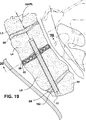
図1〜図3は、脊柱の腰部に関して、前部および後部TASIF外科的アプローチを概略的に説明する図であり、図4〜図5は、1つのTASIFインプラントまたは2つ1組のTASIFインプラントの、それぞれ対応する後部TASIF軸方向孔22または前部TASIF軸方向孔152、または2つ1組のTASIF軸方向孔221、222または1521、1522内の位置を説明する図である。複数すなわち2つまたはそれ以上のTASIF軸方向孔と、同数のTASIFインプラントまたはロッドとを図5に示し、AAIFLもしくはPAIFLと平行な直線をなすように、またはAAIFLもしくはPAIFLから頭方向に発散するように左右に並べて形成しかつ/または使用することができることを説明する。
【0058】
前述した尾骨と、仙骨を形成する癒合した仙椎S1〜S5と、腰椎L1〜L5とを含む脊柱の下方部位を、図1に側面図で示す。図1において、ヒトの腰部および仙骨部脊椎内に位置する一連の隣接する椎骨は前部、後部および軸部を備えており、各腰椎はD1〜D5で表示される損傷のないまたは損傷した椎間円板によって隔てられている。図2および図3は、仙骨および尾骨の後面図および前面図を示す。
【0059】
前部または後部TASIF軸方向孔を形成する方法および装置は、最初に、前部仙骨位、例えば図1および図3に示すS1とS2との間の関節における前部標的点にアクセスする、または後部仙骨位、例えば図1および図2に示すS2の後部椎弓切除部位にアクセスすることを含む。1つ(または複数)の可視化された、仮想上の軸方向インストゥルメンテーション/固定線は、一連の隣接する椎体、本説明図の例ではL4およびL5を貫通して軸部において頭方向、軸方向に延びている。L4、D4、L5およびD5を貫通する可視化されたAAIFLは、図1および図3に示す前部標的点からS1に沿って比較的まっすぐに延びているが、頭寄りに脊柱の曲面に沿うように湾曲させることもできる。可視化されたPAIFLは、図1および図2に示す後部椎弓切除部位S2から、より著しい曲面を有して頭寄りに延びている。AAIFLまたはPAIFLを可視化し地図作成するために、患者の脊椎を術前CTスキャンまたは磁気共鳴影像法(MRI)で検査することが行われる。
【0060】
図6は、図1〜図3において説明した前部または後部仙骨位にアクセスする外科的ステップ(S100)、前部または後部TASIF軸方向孔を形成する外科的ステップ(S200)、随意で円板および椎体を検査し、円板除去術または円板検査、円板増大、および椎骨強化バルーン補助による脊椎形成術または椎骨強化脊椎形成術を施す外科的ステップ(S300)、軸方向孔に後部および前部軸状脊椎インプラントおよびロッドまたは栓を埋め込む外科的ステップ(S400)を、簡略化した方法かつ一般的な言葉で示している。ステップS100では、前部または後部仙骨位、すなわち図3の前部標的点または図2の後部椎弓切除部位へのアクセスが得られ、あけられるべき各軸方向孔の出発点を付与するために前部または後部仙骨位が穿通される。次いで、各穿通点から、PAIFLまたはAAIFLのいずれかと一直線に並ぶように、一連の隣接する椎骨および各椎間円板を貫通して頭寄りへ、軸方向に延びる1つまたは複数の軸方向孔があけられる(S200)。軸方向孔は、仙椎体S1、S2より頭方へ1個または複数個の椎体および各椎間円板を横断することができ、また、特定の椎体または脊椎円板内の頭寄り端において終わることができる。ステップS300の処置を行うべきかどうかを決定するために、内視鏡を用いて軸方向孔を目で検査することもできる。
【0061】
前部および/または後部TASIF処置におけるステップS100の実行は、前部および/または後部経皮路の形成を完全にするために、AAIFLおよび/またはPAIFLと所定の列をなして並ぶTASIF軸方向孔より直径が小さいパイロット孔をあけることを含んでもよい。ステップS300およびS400の治療処置のいくつかは、随意で、ステップ200でTASIF軸方向孔を形成するためにパイロット孔を拡大した後ではなく、ステップ100の後にAAIFL/PAIFLパイロット孔を介して達成してもよい。
【0062】
ステップS100は、皮膚切開部から仙骨面の前部または後部それぞれの標的点にまで延びる前部または後部経皮路、または幾つかの実施形態においては、皮膚切開部からさらなる器具が横切ってもしくは貫通して導入されるようなパイロット孔の頭寄り端にまで延びる前部または後部経皮路、を形成するためのさらなる工具や器具の導入を可能にするような前部または後部経皮経路の形成を含むことが好ましい。「前部仙骨前経皮路」26(図1)は、「仙骨前腔」前部を貫通して仙骨まで延びている。後部経皮路または前部仙骨前経皮路は、1個または、もし存在するならば複数個の腰椎体および椎間円板を貫通して頭寄りに、1個または複数個の後部または前部それぞれのTASIF孔をあけるために使用することが好ましい。本明細書の文脈における「経皮的percutaneous」とは、経皮的transcutaneousまたは経皮的transdermalの場合と同様、他の医療技術による特定の処置を意味することなく、単に皮膚を介して後部または前部標的点へという意味である。一般に経皮経路は、放射線写真装置または透視検査装置によって可視化されるように、前部または後部それぞれの標的点から、少なくとも1個の仙椎体および1個または複数個の腰椎体を貫通して頭寄りに延びるAAIFLまたはPAIFLと軸方向に一直線に並んでいる。
【0063】
前記のように可視化した状態で仙骨前腔を貫通して図1に示す前部経皮路26を形成することは、医学博士J.J.Trambertが「Percutaneous Interventions in the Presacral Space:CT−guided Precoccygeal Approach−Early Experience」(Radiology 1999;213:901−904)に記載している臨床技術によって立証されるように、臨床上実現可能である。
【0064】
本発明の治療処置の幾つかは、比較的まっすぐなもしくは湾曲した前部TASIF孔、または湾曲した後部TASIF孔、またはパイロット孔を介して実施される。軸状脊椎インプラントの導入、ならびにアクセスした円板を検査するための円板検査、円板除去術および/または円板増大/置換および/または脊椎形成術、バルーン補助による脊椎形成術、固定、配列、薬剤投与、電気的刺激、または他の治療等を実施するための器具の導入は、経皮経路を付与しかつ前部または後部TASIF孔を形成することによって可能となる。
【0065】
孔形成工具セットは、まっすぐなもしくは湾曲した軸方向孔をあけるために使用時に操作できる遠位孔あけ工具、例えば機械的回転をするドリルビット、孔ぐり器、らせん錐、アブレーダなど(便宜上、集合的に孔あけヘッドまたはドリルビットと呼ぶ)を支持する細長いドリルシャフト組立て品を含む。しかし、TASIF軸方向孔は、椎体および椎間円板を機械的に穿刺または穿通するかさもなければ任意の直径または断面のTASIF軸方向孔を形成する他の工具、また、AAIFLまたはPAIFLによって可視化されるような脊椎の軸と何らかの整合性がある他の工具によっても形成することができる。本明細書では、便宜上、後部および前部TASIF軸方向孔は形成されているまたはあけられているものとみなす。
【0066】
後部TASIF軸方向孔の形成:
図7および図8は、後部経皮路を形成するステップS100と、ステップS200において孔あけ工具を用いて形成されかつ図1および図2の可視化されたPAIFLと軸方向に一直線に並ぶ仙椎、腰椎および椎間円板を貫通して延びる後部TASIF軸方向孔22とを説明する図である。同ステップS100、S200を使用して、ステップS200において拡大することができるステップS100のパイロット孔を形成することもできる。この場合、小径孔形成工具(例えば直径3.0mm)を用いて、先ずステップS100において、S1、L5およびL4を貫通する仮想上の可視化されたPAIFL20に沿って小径湾曲パイロット孔をあける。次いで、孔あけ工具を取り去り、ねじ山をつけた遠位ねじ込み先端を有する案内ワイヤをパイロット孔中に前進させ、パイロット孔の尾側端およびL4椎体の頭方部分にねじ込む。ステップS200において、湾曲案内ワイヤの進路をたどることが可能な可撓性本体を有するオーバーザワイヤ孔拡大工具を案内ワイヤの近位端をおおうように取りつけ、手でまたは機械的に回転させてワイヤ沿いに前進させる。このようにして、小パイロット孔径は拡大されて例えば直径10.0mmの前部TASIF軸方向孔22が形成され、次いで拡大工具が取り去られる。
【0067】
例示した、椎体の大きさに対する後部TASIF軸方向孔22の直径は単に代表例にすぎず、パイロット孔および孔の直径はそれぞれ約1〜10mmおよび3〜30mmの範囲で変動し得ることを理解されたい。また、複数のこのような後部TASIF軸方向孔221...22nを左右に並ぶように、またはPAIFLと概ね一直線に並んで発散するようにして形成することができることも理解されたい。
【0068】
図7において、仙骨の後面はステップS100で露出される。患者の切開部位周囲の皮膚領域は外科的に準備され、肛門は付着性のドレープを用いて外科手術領域から除外される。実際の皮膚切開部位は、PAIFLの地図を作成する、伏位の術前CTスキャン検査または磁気共鳴影像(MRI)検査によって決定することができる。ステップS100において、患者のS2の後部仙骨面をおおう皮膚が切開され、後部仙骨面の後部に延びる骨の隆起部を露出させるために皮下組織が分離される。仙骨下方の後部隆起部から小規模の椎弓切除14が行われる。椎弓切除によって露出した脊髄膜嚢および神経根は穏やかに後退させられ、脊椎管の末端部が露出される。
【0069】
仙骨への最初の穿通が露出した仙骨面と実質的に直角をなすように、細長いドリルシャフト組立て品(図示せず)は、後部標的点においてPAIFLと軸方向に一直線に並べられる。後部TASIF軸方向孔22をあけるためのドリルドライブシャフト組立て品をS2から可視化されたPAIFLに沿って受け入れるドリル案内を、随意でS2に取りつけ、露出した脊椎管および皮膚切開部の中を後部に延ばすこともできる。
【0070】
ドリルビットの前進は、従来の影像装置を用いて観察される。細長いドリルシャフト組立て品が頭寄り前部に延びるにつれて、図8に示すように、後部TASIF軸方向孔22の頭寄り域に曲面が導入される。遠位区域の曲面と脊椎の曲面との整合を保つことが必要である。このようにしてドリルビットは、各椎体の海綿質骨内にとどまった状態で、仙椎の中を頭寄り腰椎体方向に前進する。理論上は、任意の数の脊椎椎体を貫通して頭寄り軸方向に孔をあけることが可能である。後部TASIF軸方向孔22の頭寄り端は、椎体内、または円板もしくは円板腔内で終わることができる。
【0071】
前部TASIF軸方向孔の形成:
図9および図10は、ステップS100で形成された前部経皮路と、ステップS200において孔あけ工具を用いて形成されかつ図1および図2の可視化されたAAIFLと軸方向に一直線に並ぶ仙椎、腰椎および椎間円板を貫通して延びる前部TASIF軸方向孔22とを説明する図である。前述のように、同ステップS100、S200を使用して、ステップS200において拡大することができるステップS100のパイロット孔を形成することもできる。例示した、椎体の大きさに対する前部TASIF軸方向孔152の直径は単に代表例にすぎず、パイロット孔および孔の直径はそれぞれ約1〜10mmおよび3〜30mmの範囲で変動し得ることを理解されたい。また、複数のこのような前部TASIF軸方向孔1521...152nを左右に並ぶように、またはAAIFLと概ね一直線に並んで発散するようにして形成することができることも理解されたい。
【0072】
前部TASIF軸方向孔は、前部標的点から少なくとも尾側腰椎および椎間円板内へまたはそれらを貫通して、比較的まっすぐに延ばすことができる。しかし、TASIF軸方向孔の頭寄り域の曲面と脊椎の曲面との整合を保つためには、特に孔が頭寄りに延びるにしたがって、湾曲した前部TASIF軸方向孔を形成することが望ましく、または必要となろう。このようにして、ドリルビットは、各椎体の海綿質骨内にとどまった状態で、仙椎の中を頭寄りに前進する。理論上は、任意の数の脊椎椎体を貫通して頭寄りに孔をあけることが可能である。後部TASIF軸方向孔152の頭寄り端は、椎体内、または円板もしくは円板腔内で終わることができる。
【0073】
発散TASIF軸方向孔:
単一の前部または後部TASIF軸方向孔を形成する場合には、図4のTASIF軸方向孔22または152が示すように、可視化されたAAIFLまたはPAIFLそれぞれと軸方向に一直線に並んでいることが好ましい。図5に示す複数の前部または後部TASIF軸方向孔221...22nまたは1521...152nは、可視化されたAAIFLおよびPAIFLと平行であるか、または発散するように並んでいる。複数の前部または後部TASIF軸方向孔は、いずれも図1〜図3の前部または後部標的点から始まり、各TASIF軸方向孔が互いに離れてまた可視化されたAAIFLまたはPAIFLから離れて発散する状態で、頭寄りへ延びるように形成することができる。発散するTASIF軸方向孔は、1個の頭寄り椎体において互いに間隔を置いた状態で、または別々の頭寄り椎体または脊椎円板において終わる。
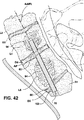
【0074】
例えば、図11〜図13は、前部標的点から始まる共通の尾側入り口孔区域152’からあけられた、3つの前部TASIF軸方向孔1521、1522および1523の群を示す図である。3つの前部TASIF軸方向孔1521、1522および1523は概ねAAIFLの曲面に沿って頭方向に延びるが、外方向に発散して、発散TASIF軸方向孔1521、1522および1523の「三脚」を形成する。共通の入り口孔区域からの発散は、孔がその中へまたはそれを貫通して延びる仙椎、L5、L4、または他の頭方椎体において始まる。S1を貫く共通の尾側入り口孔区域152’、横断する円板D5およびL4の一部の直径を発散TASIF軸方向孔1521、1522および1523の直径より大きくして、3つの細長い軸状脊椎インプラントの挿入に適応させることができ、また後述するような治療の実施を容易にすることができる。発散TASIF軸方向孔1521、1522および1523の「三脚」内に細長い軸状脊椎インプラントを挿入すると、L4、L5およびS1の癒合が実質的に強化され促進されると考えられている。図11〜図13に示すように、発散TASIF軸方向孔1521、1522および1523をさらに延ばすこともできる。発散後部TASIF軸方向孔も同様の方法で形成することができる。
【0075】
治療処置:
本発明によれば、湾曲した後部TASIF軸方向孔、または湾曲したもしくはまっすぐの前部TASIF軸方向孔を形成した後、ステップS300またはステップS400において、器具、軸状脊椎インプラント、脊椎円板インプラントおよび各種材料を用いて様々な治療処置を行うことができる。治療または治療処置の幾つかは、軸状脊椎インプラントをステップS400において埋め込まずに、ステップS300にて完了することができる。また、幾つかの症例においては、ステップS300において治療処置を行うことなく、ステップS400の治療処置を行うこともできる。本発明の器具、軸状脊椎インプラント、脊椎円板インプラントおよび各種材料を用いて行われる治療処置は下記の処置のうちの1つまたは複数を含む。すなわち、(1)内視鏡を挿入して円板検査を行い、椎体および脊椎円板の状態を視診する処置、(2)ステップS400において、TASIF軸方向孔に骨成長材を挿入することによって単純な固定術を行う処置、(3)ステップS300において、TASIF軸方向孔を介してアクセスした円板の円板部分除去術または円板完全除去術を行う処置、(4)ステップS300において、TASIF軸方向孔を介してアクセスした骨折椎体に対して脊椎形成術またはバルーン補助による脊椎形成術を行う処置、(5)ステップS400において、TASIF軸方向孔を介してアクセスした円板の円板完全除去術に引き続き、円板腔内に人工円板インプラント、自家/同種骨、または骨成長材を挿入して、固定を促進する処置または機能上の円板置換の機能を果たす処置、(6)ステップS300において、少なくとも核の一部を除去する円板部分除去術に引き続き、円板腔内に膨張性エンベロープ、他の円板インプラント、または材料を挿入し、TASIF軸方向孔を介してアクセスした円板を増大して固定を促進する処置または機能上の円板置換の機能を果たす処置、(7)ステップS400において、単一の治療として、または先に列挙した治療(1)〜(6)のいずれかと共同で、孔内に軸状脊椎インプラントを挿入する処置、(8)ステップS400において、脊椎に軸方向にかかる荷重によって、1個または複数個の椎間円板にまたがる2個またはそれ以上の椎骨の伸延および/またはショック吸収を可能にする軸状脊椎インプラントを挿入する処置、(9)ステップS300において、TASIF軸方向孔を介して、埋め込みのまたは外部の刺激装置から電気リード線を延ばし、リード線の1個または複数個の電気刺激電極を設置するかまたは隣接する椎体内もしくはそれらの間にある細長い軸状脊椎インプラントまたは脊椎円板インプラントと一体化して電気的刺激を加え、骨成長を促進するかまたは痛みを抑止する処置、(10)ステップS300において、TASIF軸方向孔を介して、埋め込みのまたは外部の薬剤ディスペンサーからカテーテルの薬剤送り出しポートまでカテーテルを延ばすか、または細長い軸状脊椎インプラントまたは脊椎円板インプラントと一体化し、隣接する椎体内もしくはそれらの間に薬剤を分与して、骨成長を促進するかまたは痛みを抑止する処置、および(11)TASIF軸方向孔を介して椎体の短距離療法を行い、脊椎の転移性疾病または腹膜後腔のアデノパシーを治療する処置。仙骨前位または後位のTASIF軸方向孔は、各治療処置の後に骨成長材料または骨セメントで埋め戻し、塞ぎ、または閉じることが好ましい。
【0076】
説明の便宜上、治療処置を図面で説明し、また下記のように、前部経皮路鞘96および前部TASIF軸方向孔152を用いて形成した前部経皮路を介して行われるように記載する。しかし、各治療処置は後部経皮路および後部TASIF軸方向孔22を介して実施し得ること、治療処置の幾つかは互いに平行なまたは発散する複数のTASIF軸方向孔を用いて有利に行われることを理解されたい。
【0077】
治療を達成するための下記の各処置において、前部TASIF軸方向孔152は、前述したように、皮膚切開部28から仙椎S1の前面の前部標的点まで仙骨前腔24を貫通して初めに挿入され、また、経皮路26を画定する前部経皮路鞘96を用いて形成される。前部経皮路鞘96の明確な形を与えられた端98は、ステップS100において仙骨S1の前面と一直線に並べられる。明確な形を与えられた端98は、仙骨に固定されるように歯またはねじ山をつけて形成される。本発明の治療処置は、前部経皮路鞘96の内腔を介して行われること、すなわち簡単に言えば、仙骨前腔24を貫通して延び軸方向に椎骨にアクセスする画定された前部経皮路26を介して行われることを理解されたい。
【0078】
脊椎円板または椎体に対する下記の各治療法は、複数個の脊椎円板もしくは椎体上で、または1個または複数個の脊椎円板および1個または複数個の椎体上で、少なくとも1つのTASIF軸方向孔を介して実施されることを理解されたい。例えば、2個の脊椎円板に単一のTASIF軸方向孔を介してアクセスし、それらを、下記の方法のうちの1つによって、先ず頭寄りの脊椎円板から治療することが可能である。次いで、頭寄りおよび尾側両脊椎円板間のTASIF軸方向孔部分を、人工軸状脊椎インプラントまたは骨成長材で適宜ふさぐ。次いで尾側の脊椎円板を治療し、尾側脊椎円板と前部または後部仙骨孔入り口点との間のTASIF軸方向孔部分を、人工軸状脊椎インプラントまたは骨成長材で適宜ふさぐ。同様にして、頭寄りおよび尾側両椎体を、脊椎形成術またはバルーン補助による脊椎形成術によって治療し、椎間円板を下記の治療法の1つを用いて治療することが可能である。便宜上、各図面においては単一の脊椎円板または椎体の治療法について記載し説明してある。
【0079】
以上のように、本発明の治療処置は、隣接する椎骨の一連の隣接する椎体を貫通して前記軸面頭寄りに延びる、可視化されたAAIFLまたはPAIFLと一直線に並ぶ仙椎の前部または後部仙骨位にアクセスすることを必然的に含む。次いで、軸方向に少なくとも尾側仙椎を貫通し、かつ一連の隣接する椎体のうちの1個または複数個の頭寄り椎体および介在する各椎間脊椎円板を貫通するかまたはその中に至る、AAIFLまたはPAIFLと一直線に並ぶ(本明細書で定義した通り)少なくとも1つの前部または後部TASIF軸方向孔を、アクセスした前部仙骨位からあける。各治療を施した後には、すべての経皮路形成工具を引き抜き、切開部位に単純な外科的縫合を施す。
【0080】
単純固定術:
従来の技術は、椎間円板が変性した隣接する椎体と椎体の間の固定を促すための、簡便かつ比較的非外傷性の方法についてはなんら提供していない。本発明の1つの治療処置は、単に、前部または後部TASIF軸方向孔に、脊椎円板に橋渡しかつ脊椎円板全体に骨の成長を達成する骨成長材を充填するものである。海綿質骨は一般に有孔性であって裂溝と空洞を備えており、それゆえに骨成長材はそのような海綿質骨の空洞および裂溝内に押し込まれることになる。本実施形態においては、椎間脊椎円板の端から端まで多数の骨成長材の橋を付与するために、複数の互いに平行なまたは発散する前部または後部TASIF軸方向孔をあけて骨成長材を充填することが望ましかろう。
【0081】
本固定治療法および本明細書に記載する他の固定治療法の目的では、「骨成長材」は下記の材料の1つもしくは複数とすることができ、または、天然もしくは人工の骨伝導性、骨誘導性、骨形成性もしくは他の固定促進性材料を含めて、所望の生理学的反応を有すると判断される他の任意の生体親和性材料とすることができる。具体的には、自家移植片、同種移植片または異種移植片を含めて、一片の皮質、海綿質、または皮質海綿質の移植骨片が使用されよう。さもなければ任意の移植骨片代用品もしくは移植骨片代用品の組合せ、または移植骨片と移植骨片代用品の組合せ、または骨誘導物質が使用できよう。このような移植骨片代用品または骨誘導物質には、ヒドロキシアパタイト、リン酸三カルシウムヒドロキシアパタイト、骨形態形成タンパク(BMP)骨セメント、石灰化または脱灰化骨誘導性骨セメントおよび再吸収性骨セメントが含まれるが、これらに限定されるものではない。再吸収性セメント材は、一般にヒドロキシアパタイト、オルトリン酸、炭酸カルシウム、および水酸化ナトリウムと水のアルカリ性溶液を用いて半液状ペーストに形成した水酸化カルシウムから成るカルシウム誘導体、またはポリプロピレンフマレートを含む組成物、またはリン酸カルシウムの混合物とすることができる。使用可能な他の組成物は、カルシウム塩充填材、N−ビニル−2−ピロリドン、および過酸化物またはフリーラジカル開始剤を含む。移植骨片材を放射線写真材料と混合して、送り出される移植骨片材を可視化し、本明細書に記載の孔、空洞および腔の適正な配置および充填を確実にすることもできる。
【0082】
幾つかの症例、例えば脊椎すべり症においては、前部または後部TASIF軸方向孔をあける前に、椎体を再配列し、かつ固定されるまでの椎骨を強化し安定させる必要がある。この症例、および強化が必要と考えられる他の症例においては、前部または後部TASIF軸方向孔の少なくとも1つに、予め形成した細長い軸状脊椎インプラントを骨成長材とともに、挿入することができる。軸状脊椎インプラントは、特別の孔曲面および大きさを有するように設計されかつ椎骨にくいこんで骨の内方成長を促するように表面処理される、表面にギザギザをつけた金属製ロッドまたは有孔性チューブとすることができる。
【0083】
この治療法によって、問題の椎骨に対して、椎間円板の治療や除去を必要としない簡便かつ比較的非外傷性のアプローチが可能となる。固定術は、骨成長材を用い、また随意で細長い軸状脊椎インプラントを用いて、以下に記載するような他の方法でも達成することができる。
【0084】
円板完全除去術:
前述したように、従来の円板完全除去処置は多くの問題を生じる円板側面の露出によって行われてきたが、本発明はそれら問題を取り除くものである。
【0085】
図14は、腰椎L4およびL5の椎体端板を直接癒合できるようにするために、または患者の脊椎円板機能を見本にして予め形成した人工円板インプラントの受容部に円板腔を付与するために、TASIF軸方向孔152を介して達成される脊椎円板、例えばD4の円板完全除去術を実施する装置を説明する部分縦断面図である。円板完全除去処置は、核、線維輪、頭寄りおよび尾側椎体の対置する皮質骨端板に付着する軟骨性端板、ならびに随意で、椎骨膜、皮質端板骨および海綿質骨を含めて、椎間円板D4を所望の深さおよび大きさに事実上完全に切開するものである。固定および/または人工円板インプラントの埋め込みのための円板腔を保持するために、患者の体を好適に支持することによって腰椎L4およびL5に伸延を適用する。切開物質を円板腔から抜き取り、固定材または人工円板インプラントを、TASIF軸方向孔152を介して円板腔に導入する。
【0086】
TASIF軸方向孔152は、除去すべき脊椎円板内で終わるか、または軸状脊椎インプラントまたは骨成長材を、切開済み円板腔に橋渡し状態のTASIF軸方向孔に挿入することになっている場合には、同脊椎円板に対して頭寄りの椎体の中まで延びる。図14は、円板D4内で終わるTASIF軸方向孔152を実線で示し、椎体の中まで延びるTASIF軸方向孔152を実線で示す図である。
【0087】
次いで、円板除去工具130を、前部経皮路鞘96の内腔によって画定される軸方向に一直線に並べられた前部経皮路26を貫通して挿入する。円板除去工具130は、円板物質をばらばらに砕きかつ皮質および海綿質骨をこすり取るための切削ヘッド134と、円板腔から破片を除去するための食塩水を流しだしながらの吸引とを用いて、血管内の障害物を砕き除去するための可撓性アテローマ切除カテーテルと同じように形成される。切削ヘッド134は、外部に配置されたエネルギー源およびたわみ制御装置140からTASIF軸方向孔152および前部経皮路26を貫通して延びる、円板除去工具シャフト136のたわみ可能かつ操縦可能な遠位端部分132に取りつけられる。遠位端部分は、たわみ機構、例えば細長い可撓性円板除去工具シャフト136の引っ張りワイヤ内腔内の引っ張りワイヤと、そこに連結した近位案内切削機構140の近位引っ張りワイヤ制御装置を用いて、角度をつけてたわませることができる。切削ヘッド134を横方向に前後に引っ張りまた軸方向孔152の周りを360度の円弧を描いてさっと動かして、脊椎円板D4の選択された症状を示す部分を、または脊椎円板D4全体を横切って切開することができ、また皮膚切開部28から延びている円板除去工具シャフト136の近位端部分を操作することによって椎体L4およびL5の端板から骨の層を切り離すことができる。円板完全除去術用切削ヘッド134および工具シャフト136の概略を示すが、必ずしも互いのまたはTASIF軸方向孔152に対する尺度で示しているわけではない。
【0088】
切削ヘッド134は、例えば、回転ワイヤブラシ、切削刃、はさみ、ねじ、ビット、延長可能/伸縮自在の回転ワイヤなどを含めた機械的カッタ、または抵抗加熱ヘッド、レーザーエネエルギーヘッドもしくは超音波エネルギーヘッドなどのエネルギー印加ヘッド、または流体ジェットなど知られている種類のものであればいずれも含むことができる。様々な形態の切削ヘッドが、例えば、先に参照した米国特許第5,976,146号、同第5,313,962号および同第5,762,629号ならびに他の米国特許第6,095,149号、同第6,127,597号、同第5,384,884号およびRE第33,258号に開示されている。しかし、従来技術の円板除去術用工具の工具シャフトは脊椎円板に側面からアクセスするように設計されており、軸方向に導入され次いで椎体の端板と端板との間の腔に入るような工具シャフトは開示されていない。
【0089】
本例の切削ヘッド134は、例えば先に参照した米国特許第5,384,884号に開示のらせん錐の方法で、切削ねじの端部または側面部を露出するためにその全体または一部を選択的に鞘(図示せず)で覆うことができる機械的ねじである。切削ヘッド134はドライブシャフトに取りつけられおり、同ドライブシャフトは、工具シャフト136のドライブシャフト内腔を貫通して、ドライブシャフトおよび切削ヘッド134を回転させるための駆動モータならびに遠位部分132をたわませるために引っ張りワイヤなどを作動させるためのたわみ制御装置にまで延びている。ここで駆動モータおよびたわみ制御装置はいずれもエネルギー源およびたわみ制御装置140内に備わっている。吸引用内腔は、遠位開口を切削ヘッド134に隣接させた状態で円板除去術用工具本体136内に備えられ、円板腔154から延びて、円板の破片を吸引するために吸引源に連結されるように適合させた側面吸引ポート138付近で終わっていることが好ましい。食塩水流しだし内腔および食塩水供給源も、吸引すべき血液および切開破片を流しだすために円板除去術用工具本体136内に一体に組み込まれていることが好ましい。
【0090】
脊椎円板D4付近での切削ヘッドの動作および動きは、透視検査または他の放射線写真可視化技術を使用して観察することが好ましい。問題部位を照明し観察するための独立の、または一体化されたたわみ性先端を有する内視鏡を用いて、円板腔154を内視鏡により可視化することも採用することができる。
【0091】
結果として生じる円板腔154は、高さが約8mmから約14mmの範囲にあり、横幅が約26mmから約32mm、前後幅が約22mmから約30mmの、ほぼ平面状の対向面を有する実質上の円板形とすることができる。しかし、円板腔154は、選択的に拡大して、尾側椎体L5の海綿質骨内へ尾側に延びかつ/または頭寄り椎体L4の海綿質骨内へ頭寄りに延びる凸面円板形とすることもできる。この円板形によれば、予め形成された円板腔154内に挿入される脊椎円板インプラント、または予め形成された円板腔154内に分与される骨成長材をより閉じ込め易くするポケットが形成される。
【0092】
TASIF軸方向孔152および経皮路26を介した、椎体D4およびD5の固定術または人工脊椎円板の円板腔154内への埋め込みは、円板腔の破片を取り除いた後で行われる。
【0093】
さらに、TASIF軸方向孔に、脊椎運動部分を内部で安定させ、一列に配列させ、かつ強化させる軸状脊椎インプラントを充填することもできる。本発明のこの治療処置は、脊椎運動部分のいかなる靭帯、筋肉および脊椎間関節も損傷することなく有利に行うことができる。
【0094】
切開円板腔にまたがる固定術:
前述したように、固定材および固定デバイスの導入を引き続き伴う従来の名円板完全または部分除去処置は、多くの問題を生じる円板側面の露出によって行われてきたが、本発明はそれら問題を取り除くものである。
【0095】
本発明の本態様の最も単純な形態において、準備されたL4およびL5の端板の固定は、図15に示すように、TASIF軸方向孔152および経皮路26を介して、骨成長材スラリーをポンプで円板腔154内へ入れることによって達成される。骨成長材を円板腔154内へ分与するために、軸方向に一直線に並んだ前部経皮路26およびTASIF軸方向孔152を介して延ばされた、図に示すようなまっすぐなまたは可撓性の先端部分を有する骨成長材分与カテーテル50を使用することができる。分与された骨成長材60をTASIF軸方向孔152から円板腔154内へ充填するために、軸方向に一直線に並んだ前部経皮路26およびTASIF軸方向孔152を介して延ばされたプランジャーを使用することもできる。次いで、尾側端開口またはTASIF軸方向孔152の全長に渡って、人工栓または骨成長材で栓をし、鞘96を引き抜く。切開部28を閉鎖し、患者は骨成長が起こるまで安静にする。
【0096】
図15で説明するこの処置は、処置を施している間に円板腔154内への充填を満足に行うことができない、または分与された骨成長材を円板腔内に閉じ込めておくことができないなどの不利を招くことがあり、また骨成長材が後に沈殿したり噴出したりするのを避けるために、ベッドで安静にして回復を待つ期間が長引くこともある。
【0097】
図16に示すように、椎体の伸延を維持し易くするために、予め形成されたロッド形の人工軸状脊椎インプラント70をTASIF軸方向孔152に挿入して、その全体または一部分をふさぐこともできる。図16に示すように、TASIF軸方向孔154が頭寄り椎体L4内まで延びている場合には、予め形成された人工軸状脊椎インプラント70もそこまで延びることができ、後述する特定の軸状脊椎インプラントの伸延およびショック吸収特性を備えることが可能である。この場合、互いに平行または発散する複数のTASIF軸方向孔を形成し、各孔内に軸状脊椎インプラントを埋め込むことが望ましかろう。予め形成されたロッド形の人工軸状脊椎インプラント70は固定機構を使用することもでき、かつ/または前記の骨成長材の1つを用いて適正な位置に固定することもできる。
【0098】
別法として、TASIF軸方向孔152および経皮路26を介して円板腔内に分与され、様々な方法でそこに保持される脊椎円板インプラントを使用する、本発明の別の態様に従って椎体の固定を達成することもできる。図17に示す1つの方法は、先に参照した米国特許第5,549,679号に記載の種類の明確な形を与えられた有孔性のしぼんだバッグ、バルーン、サックまたはエンベロープ80を、図14で形成された円板腔154内に送りだし、次いで図18に示すようにエンベロープ80を骨成長材60で満たし膨らませ、エンベロープ80の開口を閉鎖することである。有孔性の生地は、流体の通過や骨の成長を可能とする大きさであって、同時に骨成長材をエンベロープ内に閉じ込めておくには十分な小さな孔を有する。エンベロープ80は、目の詰んだ、高分子量の、ねばり強くかつ可撓性のポリマー生地、例えば高分子量ポリエチレン、ポリエステル、ポリオレフィン、ポリエチレンテレフタレート、ポリテトラフルオロエチレン、ポリスルホン、ナイロン、またはカーボン繊維ヤーン、セラミック繊維、金属繊維を含めた他の高分子量かつねばり強い材料で作ることができる。
【0099】
エンベロープ80は、様々な方法で、準備された円板腔154内に挿入することができるが、その1つが図17に示してある。バルーン開口中へ延びる充填チューブ54の内腔を貫通して延びる、可撓性押しワイヤ52の丸い先端に対してエンベロープ80を折り畳む。折り畳んだエンベロープ80、押しワイヤ52および充填チューブ54は、次に、経皮路26およびTASIF軸方向孔152を貫通して前進する管状カテーテルまたは鞘56の内腔内に挿入される。次いで、準備された伸延状態の円板腔154内にエンベロープ80を前進させ、押しワイヤ52を押しかつトルクを与えることによって畳んだエンベロープ80を広げる。押しワイヤ52の代わりに、空気または液体で膨らませる方法を用いて、円板腔内で畳んだエンベロープ80を広げることもできる。
【0100】
押しワイヤ52を引き抜き、充填チューブ54の内腔を介してエンベロープの内部から空気を吸い出し、次いで、図18に示すように、骨成長材60を充填チューブ54の内腔を介して注入する。充填されたエンベロープ80は、準備された円板腔154の形に一致し、エンベロープの開口が閉鎖されると、分与された骨成長材60はその中に閉じ込められて椎体の端板と端板の間に間隙を保持する。エンベロープの開口は、TASIF軸方向孔152および経皮路26を介して開口の周りを堅く巾着縫合し、縛ることによって、または先に参照した米国特許'679号および同'736号、ならびに米国特許第5,702,454号に記載の他の方法で閉鎖することができる。エンベロープ80内に閉じ込められた骨成長材は準備された椎体の端板と端板との間の伸延間隙を保持する。
【0101】
充填されたエンベロープ80を適正な位置に保持する1つの方法は、細長い軸状脊椎インプラント70を尾側にエンベロープ80の開口内まで前進させ、エンベロープの生地の一部分を頭側の椎体の端板に突き合せる方法である。こうすることでインプラント70と頭側の椎体の端板によってエンベロープの開口がシールされ、エンベロープは適正な位置に固定される。
【0102】
充填されたエンベロープ80を適正な位置に保持する別の方法は、円板完全除去術実施時に、凹形の準備された椎体端板を有する円板腔154を形成し、かつエンベロープ80を骨成長材で充填した時に凹面内に合致する凸面を有するエンベロープ80を形成する方法である。
【0103】
充填されたエンベロープ80を適正な位置に保持するさらに別の方法は、骨成長材を充填するやいない膨張して環状体またはタイヤの形状となり、細長い軸状の脊椎インプラント70が適合できるような、TASIF軸方向孔152と一直線に並ぶ孔を付与するエンベロープ80を形成する方法である。または、図19および図20に示すように、骨成長材を充填し膨張させるやいなや、環状体部材の形状を呈するか、または1つの平面に多くの螺旋状の巻きを有する螺旋部材の形状を呈する細長いチューブ82として、エンベロープを形成することができる。
【0104】
伸延の間隙を保持した状態で固定を促進する軸状脊椎インプラントの別の形態は、まっすぐにすることができ、かつ誘導チューブ内腔を介してまたは直接TASIF軸方向孔152を介して脊椎円板腔内に導入できるような、また脊椎円板腔154内に噴出されるやいなや図20に示す螺旋形状に戻るような、ばねの張力を有する1つまたは複数の螺旋状脊椎円板インプラント(螺旋部材)を含む。螺旋部材の断面は、円形、矩形または他の好適な形状とすることができ、螺旋の高さは円板腔154内に適合しかつ伸延状態の椎体の端板と端板の間に延びるように選択される。例えば、螺旋形状記憶を有するニッケル−チタン合金(Nitinol)の矩形断面ストリップは、まっすぐにすることができ、誘導チューブ内腔を介して前進させることができ、また円板腔154内で開放されると平らな螺旋形状を呈する。
【0105】
これら全ての場合において、図20に示すように、円板腔154内に追加の骨成長材を分与して間隙を埋めることができる。さらに、図19および図20に示すように、これら脊椎円板インプラントのいずれも、骨成長材によって円板腔154内に固定することができ、またはTASIF軸方向孔152と、環状体もしくはタイヤの形状のエンベロープ、もしくは螺旋状に配置された脊椎円板インプラントチューブ82としてのエンベロープの中心孔とを介して延びる、予め形成されたロッド形状の軸状脊椎インプラント70によって円板腔154内に固定することができる。本発明の本治療処置は、脊椎運動部分のいかなる靭帯、筋肉および脊椎間関節も損傷することなく有利に行うことができる。
【0106】
機能的円板置換インプラント:
前述したように、機能的円板置換インプラントの埋め込みを引き続き伴う従来の円板完全または部分除去処置は、多くの問題を生じる円板側面の露出によって行われてきたが、本発明はそれら問題を取り除くものである。
【0107】
本発明の本態様においては、頭側および尾側の椎体の固定を促進することなく、天然の円板の機能および特徴を模倣した様々な形態の脊椎円板インプラントをTASIF軸方向孔152および経皮路26を介して円板腔内に挿入し、様々な方法でその中に保持することができる。1つの方法は、先に参照した米国特許第5,192,326号および同第5,702,454号ならびに米国特許第5,888,220号および同第5,562,736号に記載の種類の明確な形を与えられた、しぼんだバッグ、バルーン、サックまたはエンベロープを、図14で形成された円板腔154内に送りだす方法である。次いで、エンベロープ80を治療可能な医用生体材料で充填し膨張させるが、この材料は必ずしも骨成長を促進する必要はないが、弾性であることが好ましい。米国特許第5,192,326号、同第5,888,220号および同第5,562,736号は、側面からのアプローチによって円板除去術を行い、線維輪を側面から穿通することによりできるだけ線維輪を保持した状態で核を除去する方法を記載している。本発明の本態様によれば、前記の円板完全除去術において線維輪は除去され、しぼんだエンベロープ80は、図17で示し、また前述したように、TASIF軸方向孔152および経皮路26を介して挿入され膨張させられる。エンベロープ80は準備された円板腔と形が一致し、エンベロープの開口が前述したように、また図18〜図20に示すように閉鎖されると、分与された医用生体材料はその中に閉じ込められて椎体の端板と端板の間の間隙を保持する。エンベロープ内に閉じ込められた分与医用生体材料は、準備された椎体の端板と端板の間の伸延間隙を保持するが、必ずしも固定を促進する必要はない。
【0108】
円板腔154の準備、脊椎円板インプラントの形状、および脊椎円板インプラントを適正な位置に挿入し、充填し、閉鎖し固定する方法は、脊椎固定術に関するセクションにおいて図17〜図20を参照しながら説明した方法と同じとすることができる。
【0109】
本例においては、エンベロープ80を充填する医用生体材料は、侵襲性を最小限に抑えた手段によって関節部位に導入することが可能な材料であり、また適当に水和または硬化することが可能な材料であって、例えば先に参照した米国特許第5,192,326号、同第5,702,454号、米国特許第5,888,220号および同第5,562,736号に記載のように、所望の物理化学的特性を付与することができる材料である。エンベロープ80には、液状もしくは乾燥微粒子状の、またはミクロスフェアもしくはビーズ状のヒドロゲルを、図18に示す方法で注入することができる。好ましいヒドロゲルは、ヒドロゲルポリアクリルニトリル、またはユニークなマルチブロック共重合体構造を有する任意の親水性アクリレート誘導体、または様々な応力下で自身の構造を保ちながら流体を吸収および放出する能力を有する他の任意のヒドロゲル材料の混合物として配合される。例えば、ヒドロゲルをポリビニルアルコールと水の混合物として配合することができる。エンベロープ80内に形成されるヒドロゲルコアは、天然の核のように、その有孔性生地の壁を通して流体を吸収しながら膨張する。ヒドロゲルコアは、天然の核と非常に類似した膨張の時間定数を有し、したがって2〜8(好ましくは4〜8)時間が経過すると、負荷によって5〜30%の、好ましくは15〜20%の体積変化が生じる。完全に水和している場合、ヒドロゲルコアの水分含有率は25〜65%である。好ましい実施形態のヒドロゲル材料は、商品名Hypan.RTM.でHymedix International,Inc.によって製造されている。また、先に参照した米国特許第5,192,326号において認定されているヒドロゲルおよび溶媒のいずれも、エンベロープ80を充填するために使用することができる。
【0110】
好ましいエンベロープの織構成は、体液がヒドロゲルコアと相互作用できるだけの大きさを有し、しかしヒドロゲルが漏れない程度に小さい小さな開口を複数個生じる。開口は平均径が約10マイクロメータであることが好ましいが、他の寸法も許容できる。生地を織物として説明してきたが、半透過性かつ有孔性を備える他の構成も使用できる。柔軟な材料は、流体を吸収および放出しながら、制御されたかたちでのヒドロゲルコアの膨張および収縮を可能にする。ヒドロゲルコアは、自身にかかる様々な負荷に対してクッションの役割する。ヒドロゲルコアは、負荷が減少するにつれて(例えば、患者が横になると)周囲の流体を吸収し、膨張する。この効果を達成し易くするために、好ましいエンベロープの生地は、実質的に非弾性でかつ衝撃強さを有している。この衝撃強さはヒドロゲルコアが完全に水和している場合のその膨張圧より大きく、引き裂けやヒドロゲルコアの消失を防ぐ。好適なエンベロープの材料は、 を含む。
【0111】
本発明の本治療処置は、脊椎円板の核のショック吸収機能的円板置換を可能にするものであり、脊椎運動部分のいかなる靭帯、筋肉および脊椎間関節も損傷することなく有利に行うことができる。
【0112】
円板部分除去術:
線維輪の大部分が損なわれていず、破裂または脊髄もしくは神経に対する腫張による痛みの緩和を追求する多くの症例においては、円板部分除去術または円板減圧術を行うことが好ましい。前述したように、従来の円板部分除去処置は、多くの問題を生じる円板側面の露出によって行われてきたが、本発明はそれら問題を取り除くものである。
【0113】
本発明の本態様においては、治療すべき円板の核内で終わる、または随意で、椎体の固定を容易にするために頭側の椎体の中まで延びる、前部もしくは後部TASIF軸方向孔152もしくは22を前述の方法で形成する。次いで、TASIF軸方向孔および経皮路を介して核内に器具を導入して、線維輪内へのまたは線維輪の裂溝からのすべての突起物を含めた核の全部または一部をばらばらに砕きまたは乾燥し、線維輪内および軟骨性の端板内に空隙または円板空洞を形成する。線維輪のすべての裂溝、または他の損傷、または弱体化は、例えば先に参照した米国特許第6,095,149号に記載の方法で、形成した空隙から治療することができる。単純な減圧術においては、次いで、核への入り口およびTASIF軸方向孔を、単純な細長い脊椎インプラント、骨成長材で形成した比較的短い栓、別の生体親和性材料、または骨セメントで閉鎖する。別法として、閉鎖する前に、後述するような円板増大術を施すこともできる。
【0114】
図21は、線維輪AFを損傷しない状態で、少なくとも核の一部分NPを除去するためにTASIF軸方向孔152を介して達成される、脊椎円板の円板部分除去術を実施する装置を説明する部分縦断面図である。円板除去工具110を、前部経皮路鞘96の内腔によって画定される軸方向に一直線に並べられた前部経皮路26およびTASIF軸方向孔152を介して挿入する。円板除去工具110は、円板物質をばらばらに砕きまたは乾燥するための切削ヘッド114と、線維輪に形成された空隙または空洞から破片または副産物を除去するための食塩水を流し出しながらの吸引とを用いて、血管内の障害物を砕き除去するための可撓性アテローマ切除カテーテルと同じように形成される。切削ヘッド114は、外部に配置されたエネルギー源およびたわみ制御装置140からTASIF軸方向孔152および前部経皮路26を貫通して延びる、円板除去工具シャフト116のたわみ可能かつ操縦可能な遠位端部分112に取りつけられる。
【0115】
切削ヘッド114は、例えば、回転ワイヤブラシ、切削刃、はさみ、ねじ、ビット、延長可能/伸縮自在の回転ワイヤなどを含めた機械的カッタ、または流体ジェットなどの知られている種類のものいずれも含むことができる。また切削ヘッド114は、例えば核を乾燥させ、すなわち加熱して収縮または蒸発させるような抵抗加熱ヘッド、電気焼灼装置、レーザーエネルギーヘッド、超音波エネルギーヘッドなどのエネルギー放出ヘッドであってもよい。切削ヘッド114は、例えば先に参照した米国特許第5,976,146号、同特許第6,095,149号、RE第33,258号、同第6,127,597号、同第5,313,962号、同第5,762,629号および同第5,384,884号に開示されている様々な形態の切削ヘッドを含むことができる。しかし、従来技術の円板除去術用工具の工具シャフトは脊椎円板に側面からアクセスするように設計されており、軸方向に導入され次いで椎体の端板と端板との間の腔に入るような工具シャフトは開示されておらず、またこのような方法では導入できないようになっている。
【0116】
例えば切削ヘッド114は、遠位端部分112の側面開口からループとして突き出ている切削ワイヤを含むことができ、この切削ワイヤは回転させられて核部分をスライスしてばらばらの破片にし、この破片は円板除去術用工具シャフト116の内腔を介して吸収される。遠位端部分112は、たわみ機構、例えば細長い可撓性円板除去工具シャフト116の引っ張りワイヤ内腔の中の引っ張りワイヤと、そこに連結した近位案内切削機構120の近位引っ張りワイヤ制御装置を用いて、角度をつけてたわませることができる。切削ヘッド114を横方向に進退するように引っ張りかつ/または軸方向孔152の周りを360度の円弧を描いてさっと動かして、内側にある核NPを含めて脊椎円板D4の症状を示す選択された部分を横切って切開することができ、また皮膚切開部28から延びている円板除去工具シャフト116の近位端部分を操作することによって線維輪の裂溝AFを通って突き出るその部分を切り離すことができる。円板完全除去術用切削ヘッド114および工具シャフト116の概略を示すが、必ずしも互いのまたはTASIF軸方向孔152に対する尺度で示しているわけではない。
【0117】
典型的な切削ヘッド114の伸縮自在/拡大可能切削ワイヤは、切削ヘッド114から引き伸ばすことができる一方、切削ヘッド114内へ引っ込めることができる。遠位部分112はドライブシャフトに取りつけられおり、同ドライブシャフトは、工具シャフト116のドライブシャフト内腔を貫通して、ドライブシャフトおよび切削ヘッド114を回転させるための、エネルギー源およびたわみ制御装置120に含まれる駆動モータにまで延びている。遠位部分112をたわませるために引っ張りワイヤなどを作動させるためのたわみ制御装置もエネルギー源およびたわみ制御装置120内に備わっている。吸引用内腔は、円板除去術用工具本体116内に備えられ、遠位開口を切削ヘッド114に隣接させ、脊椎円板D4の線維輪内部に形成された空洞からの核の破片を吸引するために吸引源に連結されるように適合させた側面吸引ポート118付近で終わっていることが好ましい。食塩水流出内腔および食塩水供給源も、吸引すべき切開破片を流し出すために、円板除去術用工具本体116内に一体に組み込まれていることが好ましい。
【0118】
脊椎円板D4内部での切削ヘッド114の動作および動きは、透視検査または他の放射線写真可視化技術を使用して観察することが好ましい。問題部位を照明し観察するための独立の、または一体化されたたわみ性先端を有する内視鏡を用いて、線維輪AF内に形成された空洞を内視鏡により可視化するまたは透視検査することも採用することができる。
【0119】
また、椎体D4およびD5の伸延間隙を保持しかつ線維輪AFの弱体化部分または損傷部分または破溝など修復するために、除去部分の腔内に別の器具および材料を導入することもできる。このような修復は、上記で参照した’149号特許に記載されているように、加熱処理、またはフィブリンのりなどの生体親和性パッチ材を線維輪AFの内部表面に貼付することによって行うことができる。
【0120】
本発明のこの治療処置は、脊椎運動部分のいかなる靭帯、筋肉および脊椎間関節も損傷することなく有利に行うことができる。
【0121】
円板増大および固定術:
さらに、機能的円板置換インプラントまたは骨成長材を付与して固定を達成するために、線維輪AF内に形成された空隙または空洞内に1つまたは複数の人工脊椎円板インプラントまたは他の医用生体材料を導入し、それによって線維輪AFを、導入されたインプラントまたは医用生体材料または固定促進材を適正な位置に保持ために使用することによって、脊椎円板を増大することも可能である。線維輪AFそれ自身をエンベロープとして使用し、送り出されてくる、脊椎円板インプラント、骨成長材または他の医用生体材料を含む円板増大材を収容することができる。随意で、例えば図17〜図20を参照しながら先に説明したように、円板増大材を空洞内の追加のエンベロープ内に送りだすなどによって、所望の腔内に円板増大材を収容する手段が付与される。固定を達成するために、図19〜図20を参照しながら先に説明したように、TASIF軸方向孔152を頭側椎体の中にまで延ばし、軸状脊椎インプラントおよび/または骨成長材を空洞内およびTASIF軸方向孔152に分与することもできる。また、頭側および尾側の軟骨質端板および椎体端板の一部を円板部分除去術によって除去し、椎骨を露出して、空洞に分与された骨成長材で固定を促進することもできる。
【0122】
骨成長材または他の医用生体材料を、準備された空洞の中にまたは準備された空洞内のエンベロープの中に分与することが、例えば図22〜図24に説明されている。図22は、増大工具シャフト164のたわみ性遠位部分168にある遠位出口ポート166に増大材を送りだすための増大工具シャフト164に連結された、近位増大材源162を有する円板増大工具160を示す。前部TASIF軸方向孔152またはパイロット孔150を使用する円板増大処置を図22に説明するが、図22は、前部TASIF軸方向孔またはパイロット孔を介してアクセスした円板を増大するために、円板増大工具160を用いた同処置がどのように使用されるかを伝えようとするものである。
【0123】
対向する椎体と椎体の間の脊椎円板インプラントとしての支持体を付与するために、円板増大処置は、円板増大材170として、例えば、固体微粒子材、または流体の状態で導入され線維輪AF内その部位で固体化する前述した種類の医用生体材料もしくは骨成長材を使用する。円板増大材170は、各円板の空洞内に配置した遠位出口ポート166を介して、ポンプによって、或いは直接、各空洞内に送りだすことができる。次いで、図24に示すように、脊椎円板内の尾側開口を、TASIF軸方向孔152内に挿入されて適正な位置に固定された人工栓72で閉鎖する。栓72は、椎体内に突き通されているか、または充分な保持力で椎体内に取りつけられており、脊柱に軸方向の負荷がかかるような場合には、円板増大材170にかかる圧力に抵抗し、それによって自身がTASIF軸方向孔152内に放出されるのを防ぐ。栓72は任意の好適な長さとすることができ、前部標的点まで、或いはその途中であればどこまでも延びることができる。図24に図解するように、TASIF軸方向孔の栓でふさがれていない尾側の長さ部分は、1つまたは複数の軸状脊椎インプラント70および74または骨成長材で充填することが好ましい。
【0124】
特に治療が頭側および尾側両椎体の固定術を含む場合には、別法として、円板増大工具を引き抜きながら、ポンプによってか、或いは直接円板増大材をTASIF軸方向孔152内に送りだし、円板の空洞およびTASIF軸方向孔152を充填することができる。次いで、栓72を、椎体L5のさらに尾側に挿入することができる。さらに、図21に破線で示すように、TASIF軸方向孔152を頭側に延ばすこともでき、例えば図19に示すような方法で、延ばされたTASIF軸方向孔を、増大した脊椎円板D4に橋渡し状態にある骨成長材および/または軸状脊椎インプラントで充填することもできる。
【0125】
図23は、円板空洞内でのエンベロープ80の埋め込みおよび充填を説明する図である。図17〜図20を参照しながら先に説明した方法で、エンベロープ80を埋め込み、様々な骨成長材または医用生体材料で充填し、閉鎖する。この場合、エンベロープ80は線維輪AFによって適正な位置に閉じ込められて保持され、TASIF軸方向孔152の閉鎖は、充填されたエンベロープ80が尾側に放出されるのを防ぐために前述した方法で達成される。さらに、線維輪AFに固定されたエンベロープ80または他の軸状脊椎インプラントは、図19および図20を参照しながら先に説明したように、環状体または平らな螺旋の形状となるように形づくられる。
【0126】
本発明のこの治療処置は、脊椎運動部分のいかなる靭帯、筋肉および脊椎間関節も損傷することなく有利に行うことができる。
【0127】
脊椎形成術:
前述したように、脊椎形成処置は、骨折した椎体の海綿質の中へ、椎体修復または強化用骨成長材または骨セメントを含む椎体修復または強化材を押し込むことを伴う。従来、脊椎形成術は、椎体側面の皮質骨を側面から露出し穿通することによっておこなわれてきた。前述したように、側面からのアプローチは多くの問題を生じ、本発明はそれら問題を取り除くものである。
【0128】
本発明による脊椎形成術を行う1つの方法は、単に、骨折した海綿質骨に1つまたは複数の小径のTASIF軸方向孔をあけ、そのTASIF軸方向孔にカテーテルを導入し、さらに、海綿質骨の裂溝に浸透しそれを満たすように骨成長材または骨セメントをポンプで送り込む方法である。次いで、例えば先述のようなねじ切られた栓を用いて、TASIF軸方向孔の尾側端、すなわち孔が、尾側の椎体端板を形成する比較的硬質の皮質骨を通過する場所を閉鎖する。本処置は、幾つかの異なる角度から繰り返すことができる。
【0129】
図25および図26は、骨折した椎体L4の中に、少なくとも1つのTASIF軸方向孔152を介して前述した各種骨成長材の1つを注入することによって、脊椎形成術を実施する各段階を説明する図である。ただし、本治療においては、幾つかの、互いに分岐する小径のTASIF軸方向孔152を使用することが有利である。椎体L4は幾分つぶれているものと仮定する。
【0130】
本発明の好ましい脊椎形成処置は、細長い誘導装置100の内腔を貫通して導入される、たわみ性の遠位端部92および出口ポート94を有する細長いカテーテル90を用い、後部または前部TASIF軸方向孔を介して実施される。図25に示すように、たわみ性の遠位端部92は、比較的堅いカテーテル90の内腔内に閉じ込められている時はまっすぐになっており、図26に示すように、内腔から開放されるやいなや湾曲する。遠位端部92および出口ポート94は、幾分横方向に皮質骨側へに向けることができ、次いで、誘導装置100および/または前進するカテーテル90を引っ込ませることによって、TASIF軸方向孔152から遠ざかるように任意の方向に前進させることができる。カテーテル90のテーパーをつけた端部によって、カテーテル90は、圧力下骨成長材がポンプによって送り込まれる場所である骨折した軟質の海綿質骨の中へ前進可能となる。骨成長材を送りだすために、このプロセスが何回か繰り返される。カテーテルまたは鞘を引き抜きながら、骨成長材を分与することもできる。次いで、例えば先述のようなねじ切られた栓を用いて、TASIF軸方向孔の尾側端、すなわち孔が、尾側の椎体端板を形成する比較的硬質の皮質骨を通過する場所を閉鎖する。
【0131】
本発明の脊椎形成処置は、脊椎運動部分の配列維持、強化および安定化のためにTASIF軸方向孔内に細長い軸状の脊椎インプラントを埋め込むことも随意含めて、同一のTASIF軸方向孔を使用する円板除去術、脊椎運動部分固定術、または円板増大術と共同で行うことが有利であることを留意されたい。本発明のこの治療処置は、脊椎運動部分のいかなる靭帯、筋肉および脊椎間関節も損傷することなく有利に行うことができる。
【0132】
バルーン補助による脊椎形成術:
前述したように、バルーン補助による脊椎形成術は、海綿質骨を皮質骨方向に充分圧縮できまた圧縮された椎体の形状を充分復活できるような圧力下で、弾性のバルーンまたは非弾性の明確な形を与えられたバルーンを導入し膨張させることによって、骨折した、また多くの場合つぶれた椎体内に大きな椎体空洞を形成することを伴う。次いで、バルーンをしぼませ、椎体の空洞を椎体強化のための椎体強化材で充填することができるようにバルーンを引き抜くか、またはバルーンを適正な位置に置いたままにして椎体強化材で充填することができる。従来、バルーンおよび骨成長材は椎体側面の皮質骨を側面から露出し穿通することによっておこなわれてきた。前述したように、側面からのアプローチは多くの問題を生じ、本発明はそれら問題を取り除くものである。
【0133】
図27〜図31は、本発明の本態様に従って、骨折した椎体L5のバルーン補助による脊椎形成術を行う装置を説明する図である。図27に示すように、しぼんだ状態の、非弾性、対称または非対称の、明確な形を与えられたバルーン182を、誘導装置190の内腔で、または案内ワイヤ(図示せず)越しに、または単独で前部経皮路鞘96の内腔およびTASIF軸方向孔を介して椎体D5の中に導入する。空洞形成バルーン182は、図27および図28に示すように、バルーンカテーテル本体の遠位端部分から外側に開くように遠位端部分を覆うようにして形成されるか、またはバルーンカテーテル本体の遠位端から遠位方向に延びている。前者の場合、バルーンが非対称性であれば、近位のバルーンカテーテル本体上の標識を使用して、非対称性バルーン182が椎体に対して適性な関係となる方向に向くようバルーンカテーテル180を回転させる。後者の場合、軸方向孔152全長を介して、近位のバルーンカテーテル本体上の標識を使用して、椎体内の所望の向きにしぼんだバルーンを配置する。
【0134】
次いで、図28および図29において、誘導装置190を引っ込め、かつバルーン182を透視検査による可視化を可能とする放射線写真用流体で膨張させて、海綿質骨を皮質骨方向に圧縮すると、それによってバルーン形状どおりに形を与えられた椎骨空洞184が形成され耐変形性が生じる。次いで、図30に示すように、空洞184にひとりでに骨成長材が充填されるように、バルーン182をしぼませて引き抜く。図30において、誘導装置190または直接軸方向孔152を介して分与カテーテル192を挿入し、空のバルーン182か椎耐の空同184のいずれかを骨成長材または骨セメントで充填する。または空洞形成バルーン182を、しかるべき場所で硬化し固体化する医用生体材料で充填することができる。別法として、骨成長材または骨セメントを、空洞184において閉鎖され適正な位置に放置された別の有孔性バルーンまたはエンベロープ内に閉じ込めることもできる。例えば先述のようなねじ切られた栓を用いて、TASIF軸方向孔152の尾側端、すなわち孔152が、尾側の椎体端板を形成する比較的硬質の皮質骨を通過する場所を閉鎖する。本バルーン補助による脊椎形成処置は、2つまたはそれ以上のTASIF軸方向孔および椎体の異なる領域に導入された複数のバルーンカテーテルを用いて、繰り返し行うことができる。
【0135】
バルーンまたはエンベロープを骨成長材で充填して空洞184内に放置する場合、小孔を介して流体および骨成長材が移動可能となるように、バルーンまたはエンベロープは有孔性であることが好ましい。したがって、バルーン182以外の別個の、明確な形状を与えられたバルーンを空洞内に挿入し、図17および図18の円板増大に関して先に説明したような方法で充填し、材料充填カテーテルから取り外し、バルーンまたはエンベロープの開口を閉鎖する。
【0136】
本発明のバルーン補助による脊椎形成処置は、脊椎運動部分の配列維持、強化および安定化のためにTASIF軸方向孔内に細長い軸状の脊椎インプラントを埋め込むことも随意で含めて、同一のTASIF軸方向孔を使用する円板除去術、脊椎運動部分固定術、または円板増大術と共同で行うことが有利であることを留意されたい。本発明のこの治療処置は、脊椎運動部分のいかなる靭帯、筋肉および脊椎間関節も損傷することなく有利に行うことができる。
【0137】
伸延およびショック吸収:
正常な分離を維持するために隣接する椎骨を伸延する問題、および前部脊椎のショックを吸収する問題の両問題それぞれと取り組む、本発明の別の実施形態である、後部および前部TASIF軸方向孔22および152にはまるように適合させた後部および前部軸状脊椎インプラントまたはロッド200および230を図32〜図33に示す。隣接する椎骨の伸延は、神経にかかる圧力を軽減しかつ痛みと不動性状態を緩和する。前部脊椎にかかるショック吸収もまた痛みを緩和し、より正常な前部脊椎負荷機能を復活させる。TASIF軸方向孔152にこれらTASIF軸方向脊椎インプラント200および230を埋め込むことが図34に示されている。脊椎円板を貫通してTASIF軸方向孔を延ばすことが必要であり、また、これらTASIF軸方向脊椎インプラント200および230を埋め込むに先立って、先に説明したような環状体または螺旋形状の人工円板インプラントを用いた円板増大術を行うことができる。
【0138】
図32および図34で説明したTASIF軸方向脊椎インプラント200は、尾側孔かみ合い体204と頭側孔かみ合い体206との間に延びる、ねじ付きロッド202を含む。図に示すように、ねじ付きロッド202の中央部分は、前部TASIF軸方向孔152内に挿入するためにまっすぐとすることができ、またインプラント200を後部TASIF軸方向孔22内に挿入するために湾曲させることができる。使用するときには、頭側孔かみ合い体206をTASIF軸方向孔内に完全に設置した後、矢印216で示すように、尾側孔かみ合い体204と頭側孔かみ合い体206とを互いに引き離すように、尾側孔かみ合い体204とねじ付きロッドを相互に回転させる。尾側孔かみ合い体204が、TASIF軸方向孔を横切る尾側椎骨を充分につかんだら、尾側および頭側椎骨を、尾側孔かみ合い体204と頭側孔かみ合い体206とを互いに引き離しながら伸延させる。
【0139】
これは幾つかの方法で達成することができる。図32に示すように、ネジ付きロッド204は、尾側孔かみ合い体204の雌ねじが形成された孔とかみ合うように時計回りに雄ねじが形成された尾側ロッド端208と、頭側孔かみ合い体206の雌ねじが形成された孔とかみ合うように反時計回りに雄ねじが形成された頭側ロッド端210とを有する。尾側孔かみ合い体204は、TASIF軸方向脊椎インプラント200をTASIF軸方向孔内に設置しながら回転させることによって尾側椎骨にくいこむように適合された、外部かみ合いねじ山またはフランジ212を備えて形成される。次いで、ねじ付きロッド204を、その尾側端のかみ合いと伸延工具220との回転によって回転させ、それによって尾側孔かみ合い体204と頭側孔かみ合い体206との間の距離を拡大する。別法として、ねじ付きロッド202の頭側端を頭側軸方向孔かみ合い体206に取りつけることもできる。ただし、この場合は頭側軸方向孔かみ合い体206は、ねじ付きロッド202の回転と共に回転する。
【0140】
図33のTASIF軸方向脊椎インプラント230はショック吸収機能を有し、図では2つの形態、すなわち油圧式またばね式ショック吸収機能を説明する。プランジャーロッド232は、尾側孔かみ合い体234と、頭側孔かみ合い体236との間に延びている。プランジャーロッド232の中央部分は、前部TASIF軸方向孔152内に挿入するためにまっすぐとすることができ、またインプラント200を後部TASIF軸方向孔22内に挿入するために湾曲させることができる。尾側孔かみ合い体234は、TASIF軸方向脊椎インプラント230をTASIF軸方向孔内に設置しながら回転させることによって尾側椎骨にくいこむように適合された、外部かみ合いねじ山またはフランジ242を備えて形成される。説明を簡単にするために、以下、尾側孔かみ合い体234はばね式ショック吸収機能を一体に組み込んで示しかつ説明し、頭側孔かみ合い体236は油圧式ショック吸収機能を一体に組み込んで示しかつ説明する。一方のまたは他方のショック吸収機能を、所与のTASIF軸方向脊椎インプラントまたはロッドに一体に組み込むことができることを理解されたい。
【0141】
尾側孔かみ合い体234は、ばね240とプランジャーロッド232の尾側端とを保持する内部空洞248を備えて形成される。内部空洞248への体液の侵入を阻止するために、プランジャーロッド232の尾側端を取り囲む流体バリヤガスケットを使用する。頭側孔かみ合い体236は、ショック吸収流体とプランジャーロッド232の頭側端を保持する内部空洞238を備えて形成される。内部空洞238への体液の侵入を阻止するために、プランジャーロッド232の頭側端を取り囲む流体バリヤガスケットを使用する。
【0142】
使用するときには、頭側軸方向孔かみ合い体236をTASIF軸方向孔内に完全に設置した後、挿入工具250を用いて尾側孔かみ合い体234とロッドとを相互に回転させ、尾側孔かみ合い体234のねじ山242をTASIF軸方向孔壁の中へねじ込ませる。尾側孔かみ合い体234がTASIF軸方向孔を充分とらえたら、ばねの力によって静止状態に保たれているプランジャーロッド232の長さ分、尾側椎骨と頭側椎骨とを伸延させる。頭側軸方向孔かみ合い体236と尾側孔かみ合い体234との間の距離は、患者の活動によってばね240対して脊椎が動くことで、力または荷重が腰椎体と腰椎体との間にかかったり、また力または荷重が衰えるとばねの長さが元に戻るため、矢印246の方向に長くしたり短くしたりできる。ショック吸収メカニズムの他の形態を使用して、プランジャーロッドを保持し、またプランジャーロッドがばねの力および/または油圧の力に逆らって働くことを可能にすることもできる。
【0143】
軸状脊椎インプラントまたはロッド200および230の尾側および頭側孔かみ合い体を、骨セメントまたは固定機構を用いて固定することもできる。TASIF軸方向孔内にTASIF軸方向脊椎インプラントともに配置される骨セメント材はその孔の中で硬化し、骨とTASIF軸方向脊椎インプラントの尾側および頭側両端との間に骨形成性成長による固定が生じるまで生理学的負荷に耐え得るだけの、強い固定が細長い軸状脊椎インプラントと隣接する椎骨との間に生じる。
【0144】
本発明のこの治療処置は、脊椎運動部分のいかなる靭帯、筋肉および脊椎間関節も損傷することなく有利に行うことができる。
【0145】
電気的刺激:
図35〜図37は、電気的刺激を目的として、例えば椎体もしくは脊椎円板などの問題の脊椎構造物に関して、または1つまたは複数のTASIF軸方向孔を通して隣接する神経もしくは組織、および脊柱に関して施される電気的刺激療法の実施形態を説明する図である。刺激電極は、電極を1個もしくは複数個の椎体もしくは脊椎円板内に配置するためにTASIF軸方向孔内を貫通して延びる、または脊髄もしくは神経への作用に関連して椎体もしくは脊椎円板から外方向に延びる医用電気リード線に配置された単極、両極、多極の各電極を含めて任意の知られた形態をとることができる。また、各電極は、導電性部分、または前述したような様々な位置に埋め込まれる導電性脊椎インプラントもしくは細長い軸状脊椎円板インプラントのすべてを構成することができる。リード線は、永久的に埋め込まれた電気刺激装置に接続してもよく、または一時的な電気刺激を目的として外部電気刺激装置に接続するために、閉鎖された皮膚切開部分もしくは経皮電気コネクタを介して延びていてもよい。永久的に埋め込まれる電気刺激装置(IES)はバッテリー、例えば神経刺激システムItrel3(商標名)で動かすこともできるし、または外部電力送信器、例えば神経刺激システムMattrix(商標名)から経皮的に受信した電力で動かすこともできる。これら製品はいずれもMedtronic,Inc.、Minneapolis、MNから入手可能である。また、先に参照した米国特許第6,120,502号に記載の種類の骨成長刺激装置またはEBI Medical Systems,Inc.、Parsippany、NJから入手できる種類の骨成長刺激装置も使用することができる。これらの変形態様の幾つかを、例えば図35〜図37で説明する。
【0146】
図35において、IES 300は、前部TASIF軸方向孔152中を延びるリード302を介して、例えば2個の有効電極304および306に接続されている。IES 300は、椎体L4およびL5に対し、先に参照した米国特許第6,120,502号に記載の種類の連続した陰極の電気的刺激を付与し、骨成長を促進する。また、IES 300は、付近の神経に対して、痛みを抑制するパルスの電気的刺激を付与する。患者には、患者が症状を感じた時に薬剤丸塊を投与するようにIES 300に命令を下す、一定の役割を担うプログラマがつく。
【0147】
電極304および306は、円筒形でかつその直径がリード線302の直径と同じであることが好ましい。軸方向孔の直径は、リード線302を受け入れられるだけの大きさであればよく、リード線302はTASIF軸方向孔152内にセメントで固められる。IES 300の導電性収納容器は、もどり陽極を付与する。電極304および306は任意の形状を取ることができ、1個の細長い電極と置き換えることもできる。
【0148】
図36において、IES 300は、電極312および電極314を脊柱または椎骨神経の枝付近に配置するように、分岐するTASIF軸方向孔1511および1522内に配置された第1電極312および第2電極314に延びる第1および第2のリード線308および310を介して、両電極に接続される。この場合においても、IES 300は、付近の神経に対して痛みを抑制するパルスの電気的刺激を付与する。刺激は電極312および電極314の間に適用されるか、または共通に接続された電極312および314とIES 300の収納容器との間に適用される。
【0149】
図37において、IES 300は、リード線320を介して、導電性の細長い軸状脊椎インプラント70に接続される。脊椎円板D4およびD3は円板完全除去術または円板部分除去術によって融合され、前述のように増大させる。この場合においても、IES 300は、椎体L4およびL5に対し、先に参照した米国特許第6,120,502号に記載の種類の連続した陰極の電気的刺激を付与し、骨成長を促進する。また、IES 300は、付近の神経に対して、痛みを抑制するパルスの電気的刺激を付与する。
【0150】
湾曲したTASIF軸方向孔を任意の選択された椎体に対して頭側に延し、次いで、1個または複数個の刺激電極を椎体の外側かつ脊柱または他の神経と密接に関係する位置に配置するために、同孔を椎体の側面を貫通して延すことが考えられる。髄膜への通路は、可撓性内視鏡および切削工具を使用して切り開くことができる。次いで、リード線を通路に沿って前進させ、電極を髄膜内または硬膜外の腔内に配置することができる。
【0151】
本発明のこの治療処置は、脊椎運動部分のいかなる靭帯、筋肉および脊椎間関節も損傷することなく有利に行うことができる。
【0152】
薬剤投与:
図38〜図40は、1つまたは複数のTASIF軸方向孔を介して、治療すべき問題の脊椎構造物、例えば椎体もしくは脊椎円板などに対して、または隣接する神経もしくは組織に対して、また脊柱に対して施し得る薬剤投与療法の実施形態を説明する図である。薬剤は、例えば、鈍痛を弱める薬剤、疾病または疾病の進行を治療する薬剤、または骨成長を促進する薬剤などの知られている任意の治療形態を取ることができる。薬剤投与カテーテルは、インフュージョンマイクロカテーテル、インフュージョン案内ワイヤ、Medtronic,Inc.、Minneapolis、MNから販売される種類の薬剤投与カテーテル、ならびにSynchroMed(商標)薬剤投与システムなどのバッテリーで動く埋め込み可能薬剤ディスペンサを含めて任意の知られている形態を取ることができる。薬剤投与カテーテルは、その長さ方向に沿って1つまたは複数の薬剤投与ポートを備えており、また1個もしくは複数個の椎体もしくは脊椎円板内に送出しポートを配置するようにTASIF軸方向孔を介して延びるか、または脊髄もしくは神経への作用に関連して椎体もしくは脊椎円板から外方向に延びている。薬剤投与は、前述のような様々な場所に埋め込まれる導電性脊椎円板インプラントまたは細長い軸状脊椎インプラントの一部分または全体の小孔を介して行うことができる。薬剤投与カテーテルは、永久的に埋め込まれた薬剤ディスペンサに接続してもよく、または一時的な薬剤分与を目的として外部薬剤ディスペンサに接続するために、閉鎖された皮膚切開部分もしくは経皮電気コネクタを介して延びていてもよい。永久的に埋め込まれる薬剤ディスペンサ(IDP)はバッテリーで動かすこともできるし、または外部電力送信器から経皮的に受信した電力で動かすこともできる。これらの変形態様の幾つかを、例えば図38〜図40で説明する。
【0153】
図38において、IDP 330は、前部TASIF軸方向孔152内を介して椎体L5内に配置されたカテーテルの薬剤投与ポート部分または有孔性軸状脊椎インプラント354まで延びる、薬剤投与カテーテル352に接続される。IDP 330の収納容器は、当技術分野で良く知れらている方法で内部薬剤用容器を経皮的に再充填できるように、患者の皮膚方向に向けられた充填ポートを含むことができる。IDP 330は、連続してまたは定期的に投与量の薬剤を送りだすことができる。患者には、患者が症状を感じた時に薬剤丸塊を投与するようにIDP 330に命令を下す、一定の役割を担うプログラマがつく。
【0154】
薬剤投与部分または有孔性軸状脊椎インプラント354は円筒形であることが好ましく、また軸方向孔の直径は、薬剤投与カテーテルまたは有孔性軸状脊椎インプラント354を受け入れられるだけの大きさであればよく、この場合、TASIF軸方向孔152は、円板D5および椎体S1に橋渡し状態にあるセメント栓370によって、同孔の少なくとも尾側端部分において固められる。このようなTASIF軸方向孔152は複数形成してもよく、投与薬剤をより広い範囲に送り出すために、単一の椎体または複数の椎体に複数の薬剤投与カテーテル352を付与してもよい。
【0155】
図39において、TASIF軸方向孔152は、前部仙骨の起点から、後部方向に椎体L5の頭側開口にかけて発散し、薬剤投与カテーテル332は、少なくとも1個の薬剤投与ポート334を髄膜に隣接して配置するように、IDP 330から、TASIF軸方向孔154を介して髄膜まで延びている。薬剤投与カテーテル332の遠位部分は、頭側開口から、一続きのポート334の遠位部分を問題の神経または脊髄部分に沿って配置するように延びている。薬剤投与ポート334を問題の神経または脊髄部分の付近配置するために、TASIF軸方向孔152を、任意の数の椎体を貫通してまたそれら椎体のいずれかの側壁の皮質骨を貫通して伸ばしてもよい。このようなTASIF軸方向孔152は複数形成することができ、投与薬剤をより広い範囲に送りだすために、複数の薬剤投与カテーテル332を、それら孔を介して挿入しIDP 330に接続することができる。髄膜への通路またはより頭側の硬膜外の腔への通路は、可撓性内視鏡および切削工具を使用して切り開くことができる。次いで、薬剤投与カテーテルの遠位部分を通路に沿って前進させ、薬剤投与ポートを髄膜内または硬膜外の腔内に配置することができる。
【0156】
図40において、TASIF軸方向孔152は、脊椎円板D4内または円板除去術によってそこに作られた円板腔内で終わり、薬剤投与カテーテル340は、遠位部分342および少なくとも1つの薬剤投与ポート344を脊椎円板内または円板腔内に配置するように、IDP 330から、TASIF軸方向孔154を介して延びている。薬剤は、脊椎円板または円板腔に送り出される。また、薬剤を問題の神経または脊髄部分に沿って送り出すために、薬剤投与カテーテル332の遠位部分を、もしあるならば、線維輪を貫通して問題の神経または脊柱方向に延すこともできる。薬剤投与ポート344を問題の脊椎円板、円板腔、または神経もしくは脊髄部分に近接して配置するために、TASIF軸方向孔152を、任意の数の椎体および脊椎円板を貫通して延してもよい。このようなTASIF軸方向孔152は複数形成することができ、薬剤治療を問題の多くの脊椎円板、円板腔、神経もしくは脊髄部分に施すために、複数の薬剤投与カテーテル340を、それら孔を介して挿入しIDP 330に接続することができる。
【0157】
湾曲したTASIF軸方向孔を任意の選択された椎間円板に対して頭側に延し、次いで、薬剤投与ポートを、脊椎円板の外側かつ脊柱または他の神経と密接に関係する位置に配置するために、線維輪を貫通して延すことが考えられる。髄膜への通路またはより頭側の硬膜外の腔への通路は、可撓性内視鏡および切削工具を使用して切り開くことができる。次いで、薬剤投与カテーテルの遠位部分を通路に沿って前進させ、薬剤投与ポートを髄膜内または硬膜外の腔内に配置することができる。
【0158】
本発明のこの治療処置は、脊椎運動部分のいかなる靭帯、筋肉および脊椎間関節も損傷することなく有利に行うことができる。
【0159】
脊椎構造物の短距離療法:
図41は、脊椎の転移性疾病または腹膜後腔のアデノパシーを治療するための短距離療法を目的として、腰椎体の内部あちこちに複数の放射性治療シードを挿入することを説明する部分縦断面図である。放射性シード治療法は、様々な腫瘍学的また他の医学的状態を治療するためのよく知られた、また、充分容認された処置である。短距離療法としても知られるシード治療法は、一般に、50〜100個の小さなカプセル(シード)を治療部位の中またはその周囲に埋め込むものである。カプセルは放射性同位元素を含み、身体の他の部分に悪影響を及ぼすことなく、制限された範囲の治療部位を放射線治療する。短距離療法は、前立腺癌などの様々な種類の癌治療で使用され成功をおさめている。同療法は、動脈硬化症およびバルーン血管形成術後の関節硬化症などの様々な閉塞性疾病において、組織の増殖または再増殖を予防するのにも使用されている。
【0160】
放射性治療シードは幾つかの重要な特質を有するように入念に設計されている。先ず、侵襲性を最小限に抑えた器具および技術を用いて埋め込むことができるように、その大きさは、直径約0.0025インチ、長さ約0.16インチと、かなり小くする必要がある。第2に、一般にシードを取り除くことはせず、長い年月体内に残るため、放射性同位元素を、生体親和性で保護性のパッケージの中に入れる必要がある。第3に、透過検査によって治療部位のシード位置を突き止めるために、各シードは、放射線不透過(例えばZランクの物質)標識を含むことが好ましい。第4に、保護性のパッケージおよび放射線不透過(例えばZランクの物質)標識は、同位元素の照射パターンに「陰影」を落とさないことが好ましい。第5に、照射の「ホットスポット」を避けるために、同位元素を保護性のパッケージ内に均一に分布させる必要がある。このような放射性治療シードの技術の現状は、米国特許第6,080,099号および同特許で参照される文献に開示されている。
【0161】
図41において、共通の軸孔152から分岐する複数n個の小径前部TASIF軸方向孔1511、1522...152nは、椎体L5内の前部経皮路鞘96を介してアクセスした、前部仙骨位からあけられ、複数N個の放射性シード196はそれぞれその孔内に置かれる。各放射性シード196は、小孔のカテーテルまたは注射針198を使って、また随意で注射針の内腔からシードを押し出すワイヤスチレットを使って、1つ1つの軸方向孔に置かれる。分離装置で分離される複数の放射性シードを各軸方向孔に挿入することができる。
【0162】
このようにして、側面からの腹腔鏡検査による椎体へのアプローチおよび穿通によっては非外傷的に達成することができない、最適なパターンで放射性シードを椎骨内に分布させることができる。
【0163】
集学療法:
前記治療法を組み合わせて所定の患者を治療することができる。図42は、特に脊椎固定、配列および強化を達成するための、前記諸療法の幾つかを組み合わせた集学療法を説明する部分縦断面図である。図示した集学療法においては、椎体S1、L5を貫通しL4の中へ延びる経皮路鞘96を介して、前述のように前部TASIF軸方向孔152を形成する。椎間円板D5およびD4に対して円板部分除去術を行い、それぞれの円板腔を形成する。骨成長材または骨セメント60の丸塊を、軸方向孔を介して、椎間円板D4およびD5の円板腔に注入する。次いで、図26に示す種類の脊椎形成処置により、骨成長材または骨セメント塊を、2つの椎体L4およびL5の海綿質骨のギャップおよび裂溝の中に注入する。ここで2つの椎体L4およびL5は、骨折していてもまたはつぶれていても、いなくてもよい。細長い軸状脊椎インプラント70を軸方向孔152内に挿入し、注入した骨成長材または骨セメント94および60によって、椎体L4およびL5を強化した状態で固定を達成する。
【0164】
この場合、細長い軸状脊椎インプラント70は、長さ方向に沿って延びるらせんのねじ山または固定機構を備えた、4.0mm×60.0mmの大きさのカーボンファイバーロッドであることが好ましい。本療法は、3つの分岐する軸方向孔内に前記のように埋め込んだ3本の前記細長い軸状脊椎インプラントを使用して行うことが有利である。
【0165】
前述の全処置において、脊椎、前部または後部軸方向孔の形成または治療の実施に使用される器具の導入、ならびに脊椎円板インプラントもしくは軸状脊椎インプラントもしくは他の埋め込まれた医療デバイスの可視化は、患者の体を通過するオープンMRI、透視検査法、もしくは超音波検査法、また軸方向孔を通過する内視鏡技術などを含めた従来の映像技術を使用して達成される。
【図面の簡単な説明】
【図1】 後部椎弓切除部位および前部標的点から頭方、軸方向に延びる可視化されたPAIFLおよびAAIFLを示す、脊柱の腰部および仙骨部の側面図である。
【図2】 後部椎弓切除部位および前部標的点から頭方、軸方向に延びる可視化されたPAIFLおよびAAIFLを示す、脊柱の腰部および仙骨部の後面図である。
【図3】 後部椎弓切除部位および前部標的点から頭方、軸方向に延びる可視化されたPAIFLおよびAAIFLを示す、脊柱の腰部および仙骨部の前面図である。
【図4】 図1〜図3の可視化されたPAIFLまたはAAIFLに引き続き形成されたTASIF軸方向孔内の、TASIF軸方向脊椎インプラントまたはロッドを示す腰椎の矢状方向尾側図である。
【図5】 図1〜図3の可視化されたPAIFLまたはAAIFLに平行に形成された複数の、例えば2個のTASIF軸方向孔内の、同数のTASIF軸方向脊椎インプラントまたはロッドを示す腰椎の矢状方向尾側図である。
【図6】 仙骨の後部または前部標的点に経皮的にアクセスし、図1〜図3の可視化されたPAIFLまたはAAIFLに引き続き経皮路を形成する主要な外科的準備ステップ、ならびにアクセスした椎体治療のためのTASIF孔および介入円板を形成し、そこに軸状脊椎インプラントを移植するすぐ次のステップを示す簡略化したフローチャートである。
【図7】 仙椎および腰椎を貫通する後部TASIF軸方向孔と、図1、図2の可視化されたPAIFLと軸方向に一直線にならぶ介入円板とを形成するための後部標的点にアクセスする装置を説明する部分縦断面図である。
【図8】 仙椎および腰椎を貫通する後部TASIF軸方向孔と、図1、図2の可視化されたPAIFLと軸方向に一直線にならぶ介入円板とを説明する部分拡大断面図である。
【図9】 仙椎および腰椎を貫通する前部TASIF軸方向孔と、図1、図2の可視化されたAAIFLと軸方向に一直線にならぶ介入円板とを形成するための前部標的点にアクセスする装置を説明する部分縦断面図である。
【図10】 仙椎および腰椎を貫通する後部TASIF軸方向孔と、図1、図2の可視化されたAAIFLと軸方向に一直線にならぶ介入円板とを説明する部分拡大断面図である。
【図11】 頭寄り方向に共通の尾側部分から離れた位置で発散する、複数の湾曲したTASIF軸方向孔の形成を示す部分縦断面図である。
【図12】 複数の湾曲したTASIF軸方向孔の発散を示す、図7の線12−12で切り取った部分端面図である。
【図13】 複数の湾曲したTASIF軸方向孔の発散を示す、図7の線13−13で切り取った部分端面図である。
【図14】 TASIF軸方向孔を介して達成される円板完全除去術を行い、椎体固定または予め形成した円板インプラント固定を目的とした骨成長材の挿入を可能にするための、また脊柱および神経に対して他の治療を行うための装置を説明する部分縦断面図である。
【図15】 全面的円板除去術によって形成された円板腔を骨成長材でふさぎ固定を達成するための装置を説明する部分縦断面図である。
【図16】 細長い軸状脊椎インプラントを、すでにふさがれた円板腔に橋渡し状態にあるTASIF軸方向孔に埋め込むことによって、椎体の固定を強化する装置を説明する部分縦断面図である。
【図17】 しぼんだ状態の有孔性エンベロープを送りだすことによって達成される円板完全除去術に引き続き、TASIF軸方向孔を介して円板腔内に脊椎円板インプラントを埋め込む装置を説明する部分縦断面図である。
【図18】 固定用各種骨成長材または人工脊椎円板インプラントを形成する各種医用生体材料の中から選択された材料を、図16の有孔性エンベロープに充填することを説明する図である。
【図19】 TASIF軸方向孔を介して円板腔内に送りだされる脊椎円板インプラントの別の形状である平面螺旋形状と、充填済み円板腔に橋渡し状態にあるTASIF軸方向孔内に細長い軸状脊椎インプラントを埋め込むことによって脊椎円板インプラントを保持することを説明する部分縦断面図である。
【図20】 脊椎円板インプラントの螺旋形状を説明する、図19の線20―20で切り取った軸周りの図である。
【図21】 線維輪を損傷せずに、少なくも脊椎円板の核部分のTASIF軸方向孔を介して達成される、円板部分除去術を行う装置を説明する部分縦断面図である。
【図22】 図21の空になっている繊維輪に、TASIF軸方向孔を介して、各種骨成長材および他の医用生体材料から選択された円板増大材を充填する装置を説明する部分縦断面図である。
【図23】 図21の空の円板腔内にあるバルーンに注入される材料でバルーンを膨らませることを伴う、円板増大を説明する部分拡大断面図である。
【図24】 図21の円板部分除去術または図22もしくは図23の円板増大に引き続き行われる、TASIF軸方向孔の閉鎖を説明する部分拡大断面図である。
【図25】 少なくとも1つのTASIF軸方向孔介して、骨成長材を骨折した椎体に直接注入することによって脊椎形成を行う装置を説明する部分縦断面図である。
【図26】 図20の骨折した椎体内の様々な場所に骨成長材を直接注入することを説明する、図20の線21−21で切り取った断面図である。
【図27】 海綿質骨を圧縮しまた椎体空洞を形成するために、TASIF軸方向孔内に明確な形を与えられたバルーンを導入しふくらませることを含む、バルーン補助による脊椎形成を行う装置の最初のステップを説明する部分縦断面図である。
【図28】 骨折した椎体の海綿質骨内でバルーンをふくらませる最初のステップを説明する部分縦断面図である。
【図29】 骨折した椎体の海綿質骨内でバルーンが完全にふくらんでいる状態を説明する部分縦断面図である。
【図30】 明確な形を与えられたバルーンによって形成された椎骨空洞内にまたはバルーン自体の中に、TASIF軸方向孔介して骨成長材を導入することを含む、バルーン補助による脊椎形成を行うさらに進んだステップを説明する部分縦断面図である。
【図31】 充填された状態の椎体の空洞およびTASIF軸方向孔をふさぐ栓を説明する図である。
【図32】 伸延機能を付与する細長い軸状脊椎インプラントの側面図である。
【図33】 ショック吸収機能を付与する細長い軸状脊椎インプラントの側面図である。
【図34】 1個または複数個の椎間円板にまたがる2個またはそれ以上の椎骨の伸延またはショック吸収を可能にする軸状脊椎インプラントをTASIF軸方向孔内に挿入した状態を説明する部分縦断面図である。
【図35】 リード線の1個または複数個の電気刺激電極を隣接する各椎体内、もしくは椎体と椎体の間、もしくは各椎体の外部に配置し、電気的刺激を加えて骨成長を促進するかもしくは痛みを抑止するために、またはリード線の1個または複数個の電気刺激電極を隣接する各椎体の外部に配置し、電気的刺激を加えて痛みを抑止するために、TASIF軸方向孔を介して、埋め込みのまたは外部の電気刺激装置から電気リード線を延ばした状態を説明する部分縦断面図である。
【図36】 リード線の1個または複数個の電気刺激電極を隣接する各椎体内、もしくは椎体と椎体の間、もしくは各椎体の外部に配置し、電気的刺激を加えて骨成長を促進するかもしくは痛みを抑止するために、またはリード線の1個または複数個の電気刺激電極を隣接する各椎体の外部に配置し、電気的刺激を加えて痛みを抑止するために、TASIF軸方向孔を介して、埋め込みのまたは外部の電気刺激装置から電気リード線を延ばした状態を説明する部分縦断面図である。
【図37】 リード線の1個または複数個の電気刺激電極を隣接する各椎体内、もしくは椎体と椎体の間、もしくは各椎体の外部に配置し、電気的刺激を加えて骨成長を促進するかもしくは痛みを抑止するために、またはリード線の1個または複数個の電気刺激電極を隣接する各椎体の外部に配置し、電気的刺激を加えて痛みを抑止するために、TASIF軸方向孔を介して、埋め込みのまたは外部の電気刺激装置から電気リード線を延ばした状態を説明する部分縦断面図である。
【図38】 薬剤を隣接する各椎体内、もしくは椎体と椎体の間、もしくは付近の神経および脊柱に分与して骨成長を促進するかもしくは痛みを抑止するために、または薬剤を付近の神経および脊柱に分与して痛みを抑止するために、TASIF軸方向孔を介して、埋め込みのまたは外部の薬剤ディスペンサーからカテーテルを延ばした状態を説明する部分縦断面図である。
【図39】 薬剤を隣接する各椎体内、もしくは椎体と椎体の間、もしくは付近の神経および脊柱に分与して骨成長を促進するかもしくは痛みを抑止するために、または薬剤を付近の神経および脊柱に分与して痛みを抑止するために、TASIF軸方向孔を介して、埋め込みのまたは外部の薬剤ディスペンサーからカテーテルを延ばした状態を説明する部分縦断面図である。
【図40】 薬剤を隣接する各椎体内、もしくは椎体と椎体の間、もしくは付近の神経および脊柱に分与して骨成長を促進するかもしくは痛みを抑止するために、または薬剤を付近の神経および脊柱に分与して痛みを抑止するために、TASIF軸方向孔を介して、埋め込みのまたは外部の薬剤ディスペンサーからカテーテルを延ばした状態を説明する部分縦断面図である。
【図41】 肉腫の短距離療法のために腰椎内部のあちこちに複数の放射性治療シードを挿入した状態を説明する部分縦断面図である。
【図42】 TASIF軸方向孔を介して、骨成長材または骨セメントを2個の椎体の海綿質骨および椎間円板空洞に注入することと、固定を達成するために細長い軸状脊椎インプラントを椎体強化材とともに軸方向孔に挿入することを含む、前記治療法の組合せを説明する部分縦断面図である。[0001]
The present invention relates generally to spinal surgery, and more particularly to a vertebral body that is generally aligned with a visualized transsacral or posterior axial instrument insertion / fixation line (AAIFL or PAIFL) or The present invention relates to an apparatus for forming a plurality of transsacral axial instrument insertion / fixation (TASIF) axial holes with minimal intrusion, that is, low trauma, and performing spinal therapy using the axial holes. 70% of adults experience temporary and significant back pain originating from the spinal column, the spine region. Many patients with chronic back pain and injuries that require immediate intervention require surgery to relieve the pain.
[0002]
The spinal column, that is, the spine, is composed of 33 vertebrae that accommodate the spinal cord and overlap one another in a row, and is a columnar body that flexibly supports the torso and head. The spinal vertebra (from the head or upper side) to the sacral vertebra is separated by a fibrocartilaginous intervertebral disc and joined by a joint capsule and a ligament. The top seven vertebrae are called the cervical vertebrae, and the 12 vertebrae below it are called the thoracic vertebrae or the dorsal vertebrae. The five vertebrae that continue further downward, that is, below the thoracic vertebrae are called lumbar vertebrae, and are represented by L1 to L5 in order from the top. The five vertebrae that continue further downward, that is, below the lumbar vertebrae are called sacral vertebrae, and are numbered S1 to S5 in order from the top. The last four vertebrae below the sacral vertebra are called caudal vertebrae. In adults, the five sacral vertebrae coalesce to form one bone called the sacrum, and the four trace caudal vertebrae coalesce to another one called the coccyx ("tail bone") Forming bones. The vertebrae may increase in number with additional vertebrae depending on the region, or the vertebrae may be missing.
[0003]
The typical lumbar, thoracic and cervical vertebrae consist of a ventral body or vertebral body and a dorsal arch or neural arch. In the thoracic vertebra region, the vertebral body has two radial fossa on each side, into which the tip of the rib enters. The arch surrounds a vertebral foramen formed by two pedicles and two laminas. The pedicle is a process that protrudes from the front and back of the vertebral disc body and is connected to the vertebral disc on each side. The pedicle forms the root of a vertebral arch. The vertebral arch has seven processes: one dorsal vertebral process, two lateral lateral processes, four articular processes (two upper, two lower). There is a deep recess, or inferior vertebral notch, at the lower boundary of the arch, which forms a passage or spinal canal through the vulnerable spinal cord and nerves. A continuous foramen surrounds the spinal cord. The articular processes of the spine extend behind the spinal cord.
[0004]
The bodies of the lumbar, thoracic and cervical vertebrae are continuous, but separated from each other by segments and separated by an intervertebral disc. Each spinal disc includes a fibrous cartilage shell that surrounds a central mass that absorbs and buffers the force of compressing the spinal column, ie, the nucleus pulposus (“nucleus pulposus”, referred to herein as the “nucleus”). Yes. The shell surrounding the nucleus pulposus contains a cartilaginous endplate adhered to the opposing cortical bone endplates of the head and caudal discs, and a fibrous layer of collagen fibers surrounding the nucleus pulposus and bound to the cartilage endplates. Including annulus fibrosis ("annulus fibrosis", referred to herein as "ring"). The core contains hydrophilic (water attracting) micropolysaccharide and fibrous strands. The nucleus is relatively low in elasticity, but the ring can bulge slightly outward to accept an axial load on the spinal motion segment.
[0005]
The intervertebral disc is in front of the spinal canal and is located between the opposite end faces of the vertebral bodies at the head and the caudal side, that is, between the end plates. The inferior articular process is connected via a joint with the upper articular process of the next vertebra that continues in the caudal direction (i.e. towards the foot, i.e. inferior). Several types of ligaments (supraspinal ligament, interspinous ligament, anterior longitudinal ligament, posterior longitudinal ligament, and yellow ligament) allow the spine to be held in place but allow limited movement. The two vertebral bodies, the structure between them, the intervertebral disc and the ligaments, muscles, and facet joints that connect to them are called “spine motion segments”.
[0006]
The relatively large vertebral bodies and intervertebral discs located in front of the spine occupy most of the weight support structure of the spine. Each vertebral body has a relatively strong cortical bone layer that includes the exposed surface of the outer vertebral body (including the endplate) and a weak cancellous bone that includes the central part of the vertebral body.
[0007]
Spinal extrinsic damage, disease progression, aging and birth defects cause many spinal disorders that are painful, reduce spinal flexibility, reduce spinal load bearing capacity, and spine length And / or distort the normal curvature of the spine. In the following, these spinal diseases and various treatments that have been taken or proposed clinically will be described.
[0008]
With aging, the nuclei become less fluid and become more viscous, sometimes dehydrated and contracted (also called “isolated disk absorption”). This is often painful. Furthermore, the rings tend to thicken, dry and stiffen, which reduces the ability to elastically deform under load, and is likely to cause cracks and cracks.
[0009]
One form of disk degradation occurs when a ring cracks or breaks. Such cracks may or may not be accompanied by escape of the nuclear component into or out of the ring. The crack itself is merely a morphological change, although beyond the general degree of degradation in the disc connective tissue. However, disc cracks can be painful and debilitating. It is also said that biochemical substances contained in the nucleus escape from the cracks and stimulate surrounding structures.
[0010]
Cracks may also be accompanied by a hernia, a phenomenon in which the nucleus bulges or protrudes through the crack and touches the spine and nerves due to a ring break (a “break” or “slip” disc). In a constrained disc herniation, the nucleus may protrude through the annulus, but stay within the annulus or under the posterior longitudinal ligament, and there are no nuclear fragments in the spinal canal. However, even in an intradiscal hernia, outward protrusions can compress the spinal cord and spinal nerves and cause sciatica.
[0011]
Another disc failure occurs when the disc is not unidirectional and its entire circumference is enlarging outward in all directions. When this happens repeatedly, the disk weakens and expands outward to assume a “roll” shape. The mechanical stiffness of the joints decreases, the spinal motion segment becomes unstable and the spinal cord segment shortens. Since the disk protrudes in a roll shape beyond the normal circumference, the thickness of the disk is reduced, and the intervertebral fora including the nerve root is compressed, causing pain. In addition, osteophytes may form on the outer surface of the disc roll, further phagocytosing the spinal cord and intervertebral foramen. Eventually, the head vertebral body may settle on the upper surface of the caudal vertebral body. This condition is called “lumbar spondylosis”.
[0012]
In addition, various spinal displacement diseases that occur in one or more spinal motion segments are known, either genetic or caused by degenerative disease progression or trauma. These vertebral displacement disorders include scoliosis (abnormal lateral curvature of the spine), kyphosis (spine, usually abnormal anterior curvature of the thoracic spine), hyperspondylosis (spine, usually abnormal posterior of the lumbar spine) Curvature) and spondylolisthesis (one of the vertebrae displaced forward relative to the other, usually occurring in the lumbar or cervical vertebrae). Sometimes displacement disease is accompanied by or caused by one or more vertebrae breakage or partial collapse or disc degeneration. Patients suffering from these symptoms alleviate severe deformity of the thoracic skeletal structure, loss of load bearing capacity, loss of mobility, severe pain that causes dysfunction, and often neurological deficits in neurological function Sometimes experience.
[0013]
Approximately 95% of spine surgery involves the lower lumbar vertebrae, shown as the fourth lumbar vertebra (L4), the fifth lumbar vertebra (L5), and the first sacral vertebra (S1). Persistent back pain is mainly due to degeneration of the disc that connects to L5 and S1. Conventional conservative treatments include the administration of drugs that rest on the bed or relax pain and muscles, physical therapy, and steroid injections. If conservative treatments do not give good results, spinal pain (think of destabilization) is traditionally treated by spinal fixation with or without instruments. I came. This combines the upper and lower vertebrae of the disc into a single bone block.
[0014]
Highly invasive, incisional surgical procedures have been developed and used to perform “discal excision”, where the disc is surgically removed and then the vertebral body is fused. Disc removal includes removing the nucleus, cutting off the cartilaginous endplate attached to the cortical bone endplates of the head and caudal vertebrae, and removing at least a portion of the annulus. Vertebral union involves providing exposed endplate surfaces by decolonization and further depositing bone in the disc space between the prepared endplate surfaces. Complete disc removal and fusion can be performed either by the posterior surgical route (from the patient's back) or from the anterior surgical route (from the front of the patient). The vertebrae to be removed may include only hard cortical bone or may include soft cancellous bone within the vertebra. There is controversy about the preferred method of performing these fusions for various spinal symptoms. In some cases, non-biological material is used to provide enhanced support for the bone grails (fixation system). Fixing may be performed from the rear route (rear fixing), may be performed from the front route (forward fixing), or may be performed from both sides (front-rear fixing or whole circumference fixing).
[0015]
Current treatments other than spinal fusion for disc roll symptoms and disc herniation include laminectomy, which surgically exposes the sides of the annulus and causes leakage of discs It removes the diseased part and takes a relatively long time to recover.
[0016]
There are various other surgical therapies that simply preserve the intervertebral disk and simply relieve pain, including “nucleotomy” and “disc decompression”. These remove some or most of the inner core and thereby reduce pressure to reduce the outward pressure on the wheel. Less invasive microsurgical procedures include what are known as "microlumbar discectomy" and "automated percutaneous lumbar discectomy" (automated percutaneous lumbar discectomy) Remove by sucking the nucleus with a needle extending from the side through the ring. These operations are less invasive than open surgery, but they damage the nerve root and dural sac, scar formation around the nerve, hernia recurrence at the surgical site, and excessive removal of bone May cause instability. Moreover, these require ring drilling.
[0017]
Another treatment is known as chemical nucleolysis, which is performed by injecting the enzyme chemopapain into the nucleus through a ring. This procedure has many complications such as severe pain and convulsions, which may last for weeks after the injection. There is also a limited number of patients with susceptibility reactions and anaphylactic shock.
[0018]
Although it is possible to identify damaged discs and vertebral bodies with advanced diagnostic imaging techniques, surgical procedures are so extensive that clinical results are not always satisfactory. In addition, patients who have undergone such fusion surgery have significant complications or are uncomfortable for a long time until recovery. Surgical complications include infection in the disc space, nerve root injury, hematoma formation, and destabilization of adjacent vertebrae.
[0019]
Many surgical procedures, instruments, and spinal disc implants have been described in the medical and patent literature. They are intended to provide lateral access to a less invasive, percutaneous, degenerative intervertebral disc. The instrument is for introduction through a lateral disc opening formed through the annulus to perform disc removal, implant bone forming or biomaterial or spinal disc implant in the annulus. . Alternatively, one or more laterally extending voids or holes are drilled through the disc, thereby accepting one or more laterally inserted spinal disc implants or osteogenic materials that promote healing, Accepts formed artificial and functional disc replacement implants (typically US Pat. No. 5,700,291).
[0020]
Percutaneous lateral operations and instruments for performing such disc removal are described, for example, in US Pat. Nos. RE33,258, 4,573,448, 5,015,255, 5,313,962. No. 5,383,884, 5,702,454, 5,762,629, 5,976,146, 6,095,149 and 6,127,597 and It is disclosed in PCT publication WO99 / 47055. For example, the '962 patent describes a laparoscopic technique and apparatus for incising the skin of the abdomen, through which it passes through the space at the rear of the peritoneum to the front surface of the ring of the disc, and removing the disc. The '629 and' 448 patents also describe percutaneous surgical disc treatment operations and devices for incising a patient's back and accessing the disc posteriorly therefrom.
[0021]
For example, in the '258,' 962, '884, and' 597 patents, the nucleus is crushed by various mechanical cutting heads. Alternatively, as described in the '149 patent, for example, the nuclei are dried using heat or laser irradiation to solidify the ring. Alternatively, as described in PCT '055 and' 255 patents, the disc cavity is expanded by mechanically resecting the nucleus and a portion of the cranial and caudal vertebral bodies. A cleaning liquid is introduced into the disc space or cavity, and the core fragments or by-products during drying or bone or ring fragments are aspirated from the disc space or cavity. The irrigation and aspiration can, for example, pass through the leaked disc annulus, as disclosed in the '629 patent, or the discectomy lumen, eg, as disclosed in the' 258 patent. Position and access through the access cannula relative to the opening therethrough. By visualizing other important structures in the rings and passages with arthroscopes, such as the spinal nerves, with an arthroscope, a safe and accurate means for these operations may be added.
[0022]
Such operations include invasive surgical procedures that expose the anterior or posterior (or both) of the vertebrae and intervertebral discs from the side. Extensive muscle stripping or bone preparation is required. As a result, the spinal canal is further weakened and / or surgery causes pain syndromes. Thus, currently used or proposed surgical fixation and fusion techniques involving the lower lumbar spine involve a number of problems.
[0023]
An access method and device for surgical access to the disc and vertebra from the side (reducing muscle stripping, similar to those described in the '629 and' 888 patents above) This is described in Japanese Patent No. 5,976,146. Enlarging the disturbing muscle groups and other tissues with the cavity-forming fixture set disclosed in the '146 patent allows for the use of an endoscope, and laterally onto damaged vertebrae and discs Access and perform precise surgical operations. However, it is preferred to avoid lateral exposure in less severe spondylolisthesis and other spinal injuries or defects affecting the vertebrae and discs of the lumbar and sacral vertebrae.
[0024]
A treatment for spondylolisthesis with a less invasive posterior approach is disclosed in US Pat. No. 6,086,589, where a straight line is formed from the exposed sacral surface toward the head slightly. Bone is formed through the sacrum into the L5 vertebral body, preferably after adjustment of the spine position. A threaded shaft is inserted into the hole that is straight and has a cavity, with only a side wall hole and bone growth material at the end. Preferably, the disc removal between L5 and S1 is done by a method not described, and bone ingrowth material is inserted into the head and tail cavity. In this way, only access and alignment limited between S1 and L5 is realized. This is because the straight hole and the distal end of the shaft may approach and open a hole in the anterior surface of the L5 vertebral body. This method is essentially a posterior lateral approach intended to coalesce S1 and L5, with no access to the more vertebral bodies and intervertebral discs.
[0025]
In many of these operations, the removal of the disc creates a laterally extending void in which one or more disc implants are received and bone growth material (eg, autografted bone) or preformed artificial A functional disc replacement implant is inserted. For example, a number of disc-shaped functional disc replacement implants and insertion methods have been proposed, as disclosed in US Pat. Nos. 5,258,031 and 6,019,792. Other disc-shaped or vertebral body replacement implants intended to promote bone growth and provide healing are shown, for example, in US Pat. Nos. 5,514,180 and 5,888,223. These devices and techniques overcome the problems of purely surgical techniques that mechanically immobilize the spinal region and help permanent healing of the treated adjacent vertebrae, and the length of the spinal motion segment after treatment Is intended to avoid shortening of the spinal cord and nerves. However, in these cases, in order to perform excision of the disc and vertebral body to form the caudal and cephalad vertebral bodies that are adjacent to each other, and to perform implantation and fixation thereto, laterally to the disc and vertebral body It is necessary to provide a relatively large exposed portion. Thus, the problems of current implants and surgical implantation techniques for implantation operations have not been solved, and post-operative upsets require reoperation.
[0026]
Another type of disc implant that has been used clinically for spinal fusion includes a cylindrical titanium cage that is hollow inside. This is threaded on the outside and is screwed from the side into the side hole that passes through the disc between the two adjacent vertebral bodies. Typically, this side hole is responsible for the complete disc removal of the damaged disc and the removal of the cortical bone portion of the adjacent vertebral body, forming a void that receives one or more disc implants extending laterally and axially. Is for. Bone grafts or bone growth material from the cadaver or pelvis is then filled into the central cage cavity through the cage holes to promote bone growth (or ingrowth) and to fuse the two adjacent vertebral bodies. Realize. Two such cage-type implants and the surgical instruments used to install them are disclosed, for example, in US Pat. Nos. 5,505,732 and 5,700,291. These cage-type implants and associated surgical instruments and approaches accurately drill relatively large holes for each of these cages laterally between two adjacent vertebral bodies, with the cages in each hole. Need to be screwed in. An exposed end of the cage or a cage placed side by side may stimulate nerves, in which case pain manifests again.
[0027]
These approaches are substantially related to complete disc removal, which is introduced laterally through the patient's body to the disc site and through the disc and the adjacent cortical bone. Realized by an instrument operated to cut or drill side holes. Large lateral drilling or holes impair the integrity of the vertebral body and can damage the spinal cord if the drilling is deflected backwards. The end plate of the vertebral body, which contains very hard cortical bone and helps to give the vertebral body the necessary strength, is usually weakened or destroyed during drilling. Also, because the cylindrical cage or cage is now harder than the residual bone of the vertebral body, the vertebral body tends to collapse or “telescopically”. When telescopic coalescence occurs, the length of the spinal column is shortened, and there is a risk of damaging the spinal cord and nerves that pass between the two vertebral bodies.
[0028]
Thus, the spine is mechanically stabilized from both sides of the vertebral disc that is augmented or removed so that the vertebral body fusion succeeds without the vertebral bodies joining in a telescopic manner or the disc implant being out of position. It is often necessary. One technique for spinal fixation is spinal immobilization using spinal rods (which have many examples) that are generally parallel to the spine. Usually, the posterior surface of the spine is separated and a bone screw is first secured to the appropriate vertebra pedicle or sacrum to provide the anchor point of the spinal rod. There are generally two bone screws per vertebra, that is, one on each vertebral pedicle. A clamp assembly couples the spinal rod to the screw. The spinal rod is generally curvilinear to achieve the desired curvature of the spinal column. A wire may be used to stably fix the rod to the spine. These techniques are described in more detail, for example, in US Pat. No. 5,415,661.
[0029]
Although this type of rod system is effective, the implant must be screwed or clamped to each vertebra over the posterior approach and the area to be treated. In order to sufficiently stabilize the implant system, often one vertebra above and one below the area to be treated is used for pedicle screwing for the implant. The vertebra above the second lumbar vertebra (L2) is so small that only small bone screws can be used, and the support necessary to stabilize the spine may not be obtained. These rods and screws and clamps or wires are surgically secured to the spine with a posterior approach and are difficult to manipulate. These rod assemblies are subject to large bending moments, but because the rod is located outside the spine and the holding force of the rod depends on the parts connected to it, these parts can be removed or pulled away from the vertebrae. Sometimes.
[0030]
In another approach disclosed in US Pat. Nos. 4,553,273 and 4,636,217 (both described in US Pat. No. 5,735,899), two of the three vertebrae Are joined by surgical access to the interior of the upper and lower vertebral bodies through an incision into the central vertebral body. These approaches are called “intraosseous” approaches in the '899 patent. However, in terms of removing the central vertebral body, it is more appropriate to call it an “interosseous” approach. This removal is necessary to allow the implant to be laterally inserted into the space it occupied and to have it implanted between the upper and lower vertebral bodies. In the '899 patent, these approaches are criticized for not providing adequate medial lateral and rotational support. In the '899 patent, an anterior approach was taken, forming a groove in the upper and lower vertebrae, fitting the end of the rod into this groove, and attaching to the remaining vertebral bodies of the upper and lower vertebrae with laterally extending screws. Yes. Such an approach would cause considerable damage to the ligaments and tissues that are in the process of anterior access to the vertebrae.
[0031]
In addition, using a radiopaque metal cage or other metal implant, the disc space can be imaged with a radiographic imaging device to achieve the healing achieved by bone growth between the vertebral bodies separated by the cage. It becomes difficult to evaluate the degree. Lateral insertable rigid carbon fiber or softer polymer disc implants are being considered as replacements for metal implants.
[0032]
Alternatively, US Pat. No. 5,549,679 discloses the use of a deflated porous fiber bag in a prepared cavity, which is laterally inserted and inflated with a bone growth promoting material. The prepared cavity includes a disc that is substantially ovoid removed and a portion of the adjacent vertebral body. When the bag is filled under pressure, the adjacent vertebral bodies are pulled apart, i.e. separated, resulting in a physiological separation as provided by an intact disc. The opening of the porous bag is closed in a number of ways to hold the material filled therein. This porous bag can be used in several other artificial disk designs such as those described in the '679 patent (artificial disks with elastic cores (US Pat. No. 5,071,437)) and hydrogels. It is different from that filled with beads (US Pat. No. 5,192,326).
[0033]
Also, the disc augmentation approach described in US Pat. No. 5,888,220 allows access to the disc from the side through the patient's body and punctures the ring, partially, unless it is already cracked. Disc removal is performed to remove most or all of the nucleus and create a void in the ring. The curable biomaterial is then injected into the prepared void and the material is cured in situ. One variation is to insert a deflated balloon into the prepared void, inject a curable biomaterial into the prepared void, cure the material in situ, and place the filled balloon and solidified biomaterial in situ. To leave.
[0034]
Many of the above surgical procedures and spinal implants and others that have been used clinically are described in several chapters in the book entitled “Lumbosacrum and Spine Pelvic Fixation” (Lumboscalal and Spinopelvic Fixation, edited) by Joseph Y. Margolies et al. (Lippincott-Raven Publishers, Philadelphia, 1996)). See especially
[0035]
In addition, “Lumbopelvic Fusion” (Chapter 38, Dr. Rene P. Louis, Professor of Medicine) includes spondylolisthesis repair technology (in this case, L5 is applied to S1 and intervertebral disc). If L5 and S1 are exposed to the front and the disc is removed, and the displacement is significant, the direction of L5 with respect to S1 is mechanically adjusted using a reduction tool. A fibula graft and a Judet screw are inserted as a dowel through a hole extending through the L5 through the caudal side through S5. For example, bone material harvested from a patient is inserted into the hole along the screw, the disc space is filled with bone and sutured to the screw, which is then vertebral surface In order to function as a spacer implant occupying the disc extracted from between L5 and S1.External bridge plate or rod may optionally be installed.To correct severe spondylolisthesis, A posterior or anterior approach using a reduction device is required, but this leads to tissue damage, and because of this approach, and from the need, the caudal hole and the inserted Judet screw only L5 and S1 Can be traversed.
[0036]
A similar anterior approach for treating spondylolisthesis is disclosed in US Pat. No. 6,056,749. In this approach, an opening in the hole is formed in the vertebra near the head and through the intervertebral disc into the caudal vertebral body, the disc is removed and the disc cage is inserted into the disc space from the side, A threaded shaft with an elongated cavity is inserted into the hole and through the opening into the disc cage. According to the technique described in Chapter 38 of the above publication, the disc cage is an alternative to the harvested bone disc insert, the connecting intersection with the shaft is an alternative to the sutured portion, and the harvested bone disc is Used to connect the insert to the screw.
[0037]
In further discussion of spinal diseases, the vertebral body is associated with osteoporosis and certain types of erosion, as described in US Pat. Nos. 4,969,888, 5,972,015 and 6,066,154. As the sexual disease develops, it becomes thin and weak to the extent that one or more vertebral body compression fractures occur. Even in healthy vertebral bodies, vertebral body compression fractures can occur due to injury. When it is heavy, the vertebral body collapses, shortening the length of the vertebral body and the spine, or causing the curvature of the spine at an abnormal location. As noted in the '888 patent, vertebral compression fractures due to osteoporosis are now treated with bed rest, analgesics, and hydration by intravenous infusion for a week after the problem occurs. After this step, a soft or hard corset is worn depending on the physician's preference. In most cases, however, the corset is not worn. In many cases, the discomfort felt by the patient is greater than that caused by a fracture of the vertebral body. Fracture pain lasts from 2 to 8 months. In many cases, patients with fractured vertebral bodies due to osteoporosis will need to spend approximately one week at an emergency hospital and a few weeks at additional treatment facilities until the pain is relieved and they can walk alone. is there. With current therapies, the state of the vertebral body is not substantially changed.
[0038]
The '888 patent describes a “balloon assisted spine formation” method that restores the collapsed and compressed fracture height through a posterior lateral approach from the skin entry point determined using X-rays. If the point is approximately 10 cm from the midline and there is a rib at that level, then it is just below the rib. The guide pin is extended from the incision toward the vertebral body, penetrates through the cortical bone, and is inserted into the cancellous bone at a predetermined depth. A cannula is inserted over the guide pin and its distal end is attached to the external cortical bone of the vertebral body. Extend the drill through the cannula and use it to drill into the cancellous bone to enlarge the cavity to be processed. An inflatable balloon is inserted through a cannula in a deflated state and inflated within the vertebral body to form a disk or checker shape. Balloon inflation compresses the cancellous bone toward the external cortical wall of the vertebral body, further expanding the cavity and filling the cortical bone (according to the description of this patent) into the cortical bone. Balloon inflation also restores some vertebral body height. The balloon is then deflated and removed, and the cavity is washed with saline. At the same time, the cavity is aspirated and filled with fluid synthetic bone material or methyl methacrylate so that it will be in a solidified condition as it passes through the cannula. Thanks to the compressed cortical bone or bone marrow, fluid does not substantially escape through the fracture.
[0039]
The '015 and' 154 patents describe generally similar operational steps, but use an improved, irregularly shaped balloon, which approximates the shape inside the vertebral body to inflate it, As a result, the cancellous bone can be compressed to the maximum extent. The balloon is made of an inelastic material, and maintains its outer shape due to various shape restrictions when inflated. This operation is also referred to as “Kyphoplasty” by Kyphon, the assignee of the '015 and' 154 patents.
[0040]
Other treatments that promote bone growth in the vertebral body and fuse the vertebral body include those that use or do not use a pre-formed spinal disc replacement implant, or bone growth materials that are discs or vertebral bodies. Some are inserted into the body, and others stimulate bone growth by applying electrical energy. Several natural or artificial osteoconductive, osteoinductive, osteogenic and other healing-promoting materials are disclosed in US Pat. No. 6,123,705. A system and method for transmitting electrical energy to a pre-formed spinal disc replacement implant to promote bone growth and fusion around the implant and between the opposing endplates of the cranial and caudal vertebral bodies is disclosed in US Pat. , 120, 502.
[0041]
Such operations include invasive surgical procedures that expose the anterior or posterior (or both) of the vertebrae and intervertebral disc from the side. Extensive muscle stripping or bone preparation is required. As a result, the spinal canal can be further weakened and / or cause pain syndromes induced by surgery. Thus, currently used or proposed surgical fixation and fusion techniques involving the lower lumbar spine involve a number of problems.
[0042]
An access method and device for surgical access to the disc and vertebra from the side (reducing muscle stripping, similar to those described in the '629 and' 888 patents above) This is described in Japanese Patent No. 5,976,146. Enlarging the disturbing muscle groups and other tissues with the cavity-forming fixture set disclosed in the '146 patent allows for the use of an endoscope, and laterally onto damaged vertebrae and discs Access and perform precise surgical operations. However, it is preferred to avoid lateral exposure in less severe spondylolisthesis and other spinal injuries or defects affecting the vertebrae and discs of the lumbar and sacral vertebrae.
[0043]
A treatment for spondylolisthesis with a less invasive posterior approach is disclosed in US Pat. No. 6,086,589, where a straight line is formed from the exposed sacral surface toward the head slightly. Bone is formed through the sacrum into the L5 vertebral body, preferably after adjustment of the spine position. A threaded shaft is inserted into the hole that is straight and has a cavity, with only a side wall hole and bone growth material at the end. Preferably, the disc is removed between L5 and S1, and the bone ingrowth material is inserted into the head and tail gaps. In this way, only access and alignment limited between S1 and L5 is realized. This is because the straight hole and the distal end of the shaft may approach and open a hole in the anterior surface of the L5 vertebral body. This method is essentially a posterior lateral approach intended to coalesce S1 and L5, with no access to the more vertebral bodies and intervertebral discs.
[0044]
A variety of orthopedic implants have been proposed and used in clinical settings to stabilize damaged bones or to fix artificial hips, knees, and finger joints. Often, a rod or joint support is placed longitudinally in a longitudinal hole drilled in an elongated bone such as the femur. A surgical method for stabilizing a damaged femur or other long bone using an elongated rod and a resorbable cement is disclosed in US Pat. No. 5,514,137. To accomplish placement of the rod within any single bone, one end of the bone is exposed and a groove is formed from the exposed end to the other end. A hollow rod is then inserted and then resorbable cement is injected through the hollow rod to secure the distal end of the rod and the cancellous bone tissue surrounding the rod. A cement insertion device can also be used for cement injection. U.S. Pat. No. 5,514,137 briefly mentions the possibility of placing the spine or a rod adjacent to the spine in a similar manner, but does not describe any specific method or device .
[0045]
In many of the surgical procedures, a drilling tool is used to drill a straight hole in the vertebra. For example, U.S. Pat. Nos. 4,265,231, 4,541,423, and 5,002,546 describe making a hole in the other bone. '231 is a pre-curved outer sheath that is used to open a curved suture retaining end opening hole in a bone so that the suture is applied from one open end of the hole to the other open end. Describes an elongated perforated drive shaft. '423 describes an elongate flexible perforated drive shaft encapsulated within a malleable outer sheath that can be manually curved before perforating. '546 describes a complex curved drilling tool that uses a pivot rocker arm and a curved guide for a drill bit to drill a fixed curved path through bone. Both of these methods dictate the formation of a curved hole along a predetermined fixed curved surface of the outer sheath or guide. The sheath or guide advances while forming the hole, making it impossible for the user to adjust the curved surface of the hole to follow the physiological features of the bone through which the hole passes.
[0046]
All of the above and other patents referred to herein that access a single spinal disc or vertebra to perform the treatment are accessed by an external approach with weakening of the spinal fixation area. There remains a need for methods and devices for performing spinal therapeutic procedures in a manner that minimizes invasiveness and minimizes trauma.
[0047]
A preferred embodiment of the present invention invades one or more of a series of vertebral bodies or spinal discs or other spinal structures of a human spine with an anterior surface, a posterior surface and an axial surface to be treated. With methods and devices for performing therapeutic treatment in a manner that minimizes gender and minimizes trauma. The present invention is implemented using the following method and associated apparatus. That is,
A method for accessing the anterior or posterior sacral position of the sacral spine extending through the series of adjacent vertebral bodies and intervertebral discs and aligned with the visualized transsacral AAIFL or PAIFL and associated apparatus,
From the accessed sacral position, penetrate at least each vertebral body of the sacrum, penetrate into or through at least one lumbar vertebral body, and further into or through the intervertebral disc, in alignment with AAIFL or PAIFL A method of forming a TASIF axial hole following the head in the axial direction, thereby forming an axial disk opening, and associated apparatus, and
A method and associated apparatus for performing a therapeutic procedure on one or more of a series of adjacent vertebral bodies or undamaged or damaged intervertebral discs.
[0048]
Access to the anterior sacral position is preferably accomplished by forming an anterior access path that extends from the skin incision through the anterior sacral cavity to the anterior target point. Access to the posterior sacral position is preferably done by surgically exposing the posterior target point.
[0049]
One or more posterior TASIF axial holes are formed starting from the exposed posterior target point and extending in the head direction in line with the visualized transsacral PAIFL. The posterior TASIF axial hole is head to head relative to the posterior target point so that the posterior transsacral axial hole can extend to the head and to the head end of the hole in one of each lumbar body or disc. It has a curved surface that is aligned with the anatomical curved surface of the sacrum and lumbar vertebrae.
[0050]
One or more anterior TASIF axial holes are formed starting from the accessed anterior target point and extending in a direction axial to the head (ie, the spinal axis) in line with the visualized transsacral AAIFL Is done. The anterior TASIF axial hole is straight to the head with respect to the accessed anterior target point or curved to follow the anatomical surface of the sacral and lumbar vertebrae, and one lumbar body or disc The head extends toward the head end of the hole.
[0051]
In either case, the “array” of single front or rear TASIF axial holes is either coaxial or parallel with the visualized AAIFL or PAIFL, respectively. The arrangement of the plurality of front or rear TASIF axial holes is either a parallel or divergent arrangement with the visualized AAIFL or PAIFL, respectively. All such arrangements are defined herein as axial.
[0052]
The therapeutic treatment includes one or more of the following devices and methods. That is,
(1) Apparatus and method for performing spinoplasty or balloon-assisted spinoplasty on a fractured vertebra accessed through a TASIF axial hole;
(2) Apparatus and method for performing disc partial removal or disc complete removal on a disc accessed through a TASIF axial hole,
(3) An apparatus and method for inserting a bone growth material into the disc cavity following the complete discectomy for the disc accessed through the TASIF axial hole to achieve fixation,
(4) an apparatus and method for inserting an artificial disc implant into a disc cavity instead of a disc accessed and removed via a TASIF axial hole;
(5) Inserting artificial disc implants, other disc implants or medical biomaterials into the space in the annulus fibrosus in order to increase the discs accessed through the TASIF axial hole following the partial discectomy Apparatus and method,
(6) including an axial spinal implant that allows for the extension and / or shock absorption of two or more vertebrae across one or more intervertebral discs by axial loading on the spine; Apparatus and method for inserting an axial spinal implant into a TASIF axial bore;
(7) Electricity to the vertebral structure in question via the TASIF axial hole to promote bone growth or to suppress pain or to suppress pain associated with spinal column or nerve surgery Device and method for applying sexual stimulation,
(8) Drugs to the vertebral structure in question via the TASIF axial hole to promote bone growth or to suppress pain, or to suppress pain associated with spinal column or nerve surgery Device and method,
(9) devices and methods for implanting radioactive seeds in the vertebral body to treat metastatic disease of the spine or adenopathy of the retroperitoneal cavity; and
(10) Apparatus and method for performing diagnostic procedures, eg, viewing the spine through a hole.
[0053]
In the context of the present invention, “disc segment removal” involves removing or drying any part of the nucleus through the axial disc opening, while “disc complete removal” means at least vertebral removal. It involves perforating or removing a portion of the annulus fibrosis.
[0054]
Thus, to remove vertebra and / or spinal disc material and to introduce bone growth materials, other medical biomaterials, devices and instruments for the purpose of completing the individual steps of each therapeutic procedure, Front or rear TASIF axial holes can be used. Once the therapeutic procedure is complete, fixation and / or strengthening of the fixation area or spinal motion part to hold the implanted device or material in place and / or align to seal the vertebral body and disc Therefore, it is preferable to close the TASIF axial hole. The TASIF axial hole can be completely plugged or plugged with a bone growth material, or a preformed axial spinal implant, or a plug that engages the vertebra.
[0055]
The above and other advantages and features of the present invention will be more readily understood by reading the preferred embodiments described below with reference to the drawings. Throughout the drawings, the same reference numerals denote the same structures.
[0056]
First, note the following description regarding FIGS. 1 to 6 cited from priority
[0057]
FIGS. 1-3 schematically illustrate an anterior and posterior TASIF surgical approach with respect to the lumbar region of the spine, and FIGS. 4-5 illustrate one TASIF implant or a set of two TASIF implants. , Corresponding rear TASIF
[0058]
The lower part of the vertebral column including the aforementioned coccyx, the fused sacral vertebrae S1 to S5 forming the sacrum, and the lumbar vertebrae L1 to L5 is shown in a side view in FIG. In FIG. 1, a series of adjacent vertebrae located within the human lumbar and sacral vertebrae comprise an anterior portion, a posterior portion and a shaft portion, each lumbar vertebra being an intact or damaged vertebra, designated D1-D5. They are separated by a disc. 2 and 3 show posterior and anterior views of the sacrum and coccyx.
[0059]
The method and apparatus for forming an anterior or posterior TASIF axial hole initially accesses an anterior sacral position, eg, an anterior target point in the joint between S1 and S2 shown in FIGS. 1 and 3, or This includes accessing the posterior sacral position, for example, the posterior laminectomy site of S2 shown in FIGS. One (or more) visualized, virtual axial instrumentation / fixed line is headed at the shaft through the series of adjacent vertebral bodies, L4 and L5 in the illustrated example. , Extending in the axial direction. The visualized AAIFL penetrating L4, D4, L5, and D5 extends relatively straight along S1 from the anterior target point shown in FIGS. 1 and 3, but along the curved surface of the spinal column toward the head Can be curved. The visualized PAIFL extends from the posterior laminectomy site S2 shown in FIG. 1 and FIG. To visualize and map the AAIFL or PAIFL, the patient's spine is examined with a preoperative CT scan or magnetic resonance imaging (MRI).
[0060]
FIG. 6 illustrates a surgical step (S100) for accessing the anterior or posterior sacral position described in FIGS. 1-3, a surgical step (S200) for forming an anterior or posterior TASIF axial hole, optionally a disc. And a surgical step (S300) to examine the vertebral body, perform disc removal or disc examination, disc augmentation, and spine or spine augmentation with vertebral reinforcement balloon assistance (S300), posterior and The surgical step of implanting the anterior axial spinal implant and the rod or plug (S400) is shown in a simplified manner and in general terms. In step S100, access to the anterior or posterior sacral position, ie, the anterior target point of FIG. 3 or the posterior laminectomy site of FIG. 2, is provided to provide a starting point for each axial hole to be drilled. The anterior or posterior sacral position is penetrated. Then, from each penetration point, one or more axial holes extending axially through the series of adjacent vertebrae and each intervertebral disc toward the head so as to be aligned with either PAIFL or AAIFL Is opened (S200). The axial hole can traverse one or more vertebral bodies and each intervertebral disc from the sacral vertebral bodies S1, S2 to the head, and can also be positioned near the head within a particular vertebral body or spinal disc. Can end at the edge. In order to determine whether the treatment of step S300 should be performed, the axial hole can also be visually inspected using an endoscope.
[0061]
Execution of step S100 in the anterior and / or posterior TASIF procedure is performed in order to complete the formation of the anterior and / or posterior percutaneous tract, with the TASIF axial holes aligned with the AAIFL and / or PAIFL. It may include drilling pilot holes of smaller diameter. Some of the therapeutic treatments in steps S300 and S400 are optionally accomplished through the AAIFL / PAIFL pilot hole after
[0062]
Step S100 may be an anterior or posterior percutaneous tract that extends from the skin incision to an anterior or posterior target point on the sacral surface, or in some embodiments, additional instruments across or through the skin incision. The formation of an anterior or posterior percutaneous pathway that allows the introduction of additional tools or instruments to form an anterior or posterior percutaneous pathway that extends to the proximal end of the pilot hole as introduced It is preferable to contain. The “anterior sacral percutaneous passage” 26 (FIG. 1) extends through the anterior portion of the “pre-sacral cavity” to the sacrum. The posterior percutaneous tract or anterior sacral percutaneous tract is passed through one or more lumbar vertebral bodies and intervertebral discs, if any, one or more posterior or anterior It is preferable to use it for making TASIF holes in each part. “Transcutaneous percutaneous” in the context of the present specification, as in the case of transcutaneous transcutaneous or transcutaneous transdermal, does not imply a specific treatment by other medical techniques, simply through the skin or It means to the front target point. In general, the percutaneous route penetrates at least one sacral vertebra and one or more lumbar vertebral bodies from an anterior or posterior target point as visualized by a radiographic or fluoroscopic apparatus. It is aligned with AAIFL or PAIFL extending in the axial direction in a straight line.
[0063]
The formation of the anterior
[0064]
Some of the therapeutic procedures of the present invention are performed through a relatively straight or curved front TASIF hole, or a curved rear TASIF hole, or pilot hole. Introduction of axial spinal implants, disc examination to examine the accessed disc, disc removal and / or disc augmentation / replacement and / or spinoplasty, balloon-assisted spinoplasty, fixation, alignment The introduction of devices for performing drug administration, electrical stimulation, or other treatments, etc. is made possible by providing a transdermal route and forming an anterior or posterior TASIF hole.
[0065]
A drilling tool set is a distal drilling tool that can be manipulated at the time of use to drill straight or curved axial holes, such as a mechanically rotating drill bit, boring tool, helical cone, abrader, etc. An elongated drill shaft assembly that supports a drilling head or drill bit). However, TASIF axial holes can be mechanically punctured or penetrated through vertebral bodies and intervertebral discs, or other tools that form TASIF axial holes of any diameter or cross-section, and also by AAIFL or PAIFL It can also be formed by other tools that have some alignment with the axis of the spine as visualized. In this specification, for convenience, the rear and front TASIF axial holes are considered to be formed or drilled.
[0066]
Formation of rear TASIF axial hole :
7 and 8 show a step S100 for forming a posterior percutaneous tract, and a sacral vertebra formed in step S200 using a drilling tool and aligned axially with the visualized PAIFL of FIG. 1 and FIG. It is a figure explaining the rear part TASIF
[0067]
Illustrated, the diameter of the posterior TASIF
[0068]
In FIG. 7, the posterior surface of the sacrum is exposed in step S100. The skin area around the patient's incision is surgically prepared and the anus is removed from the surgical area using an adhesive drape. The actual skin incision site can be determined by prone CT scan or magnetic resonance imaging (MRI) examination of the prone position, which creates a map of the PAIFL. In step S100, the skin covering the posterior sacral surface of S2 of the patient is incised, and the subcutaneous tissue is separated to expose the ridges of the bone extending to the posterior portion of the posterior sacral surface. A
[0069]
An elongated drill shaft assembly (not shown) is axially aligned with the PAIFL at the posterior target point so that the initial penetration into the sacrum is substantially perpendicular to the exposed sacral surface. A drill guide that accepts a drill drive shaft assembly for drilling the posterior TASIF
[0070]
The advancement of the drill bit is observed using a conventional imaging device. As the elongated drill shaft assembly extends toward the front of the head, a curved surface is introduced into the head of the rear TASIF
[0071]
Formation of front TASIF axial hole :
9 and 10 show the anterior percutaneous tract formed in step S100 and the sensation that is axially aligned with the visualized AAIFL formed in FIG. 1 and 2 using a drilling tool in step S200. FIG. 6 is a diagram illustrating a TASIF
[0072]
The anterior TASIF axial hole can extend relatively straight from the anterior target point into or through at least the caudal lumbar and intervertebral discs. However, in order to maintain the alignment of the curved surface of the TASIF axial hole head and the curved surface of the spine, it is desirable to form a curved front TASIF axial hole, particularly as the hole extends closer to the head, Or it will be necessary. In this way, the drill bit advances forward in the sacral spine while staying within the cancellous bone of each vertebral body. Theoretically, any number of spinal vertebral bodies can be drilled through the head toward the head. The head end of the posterior TASIF
[0073]
Divergent TASIF axial hole :
When forming a single front or rear TASIF axial hole, it should be axially aligned with each visualized AAIFL or PAIFL as shown by TASIF
[0074]
For example, FIGS. 11-13 show three front TASIF
[0075]
Therapeutic treatment :
According to the present invention, after forming a curved posterior TASIF axial hole, or a curved or straight anterior TASIF axial hole, in step S300 or step S400, the instrument, axial spinal implant, spinal disc implant and Various therapeutic treatments can be performed using various materials. Some of the treatments or therapeutic procedures can be completed in step S300 without implanting the axial spinal implant in step S400. In some cases, the therapeutic treatment in step S400 can be performed without performing the therapeutic treatment in step S300. The therapeutic procedures performed using the devices, axial spinal implants, spinal disc implants and various materials of the present invention include one or more of the following procedures. That is, (1) a procedure for inserting an endoscope to perform a disc examination and visually inspecting the state of a vertebral body and a spinal disc, and (2) inserting a bone growth material into the TASIF axial hole in step S400. (3) In step S300, in step S300, in step S300, in step S300, in step S300, in the step S300, in step S300, in step S300, in step S300, A procedure for performing a spinoplasty or balloon-assisted spinoplasty on the fractured vertebra accessed via the TASIF axial hole, (5) a disc of the disk accessed via the TASIF axial hole in step S400 A procedure or functional circle that facilitates fixation by inserting an artificial disc implant, autologous / homogeneous bone, or bone growth material into the disc cavity following complete removal. (6) In step S300, following the disc segment removal procedure to remove at least a portion of the nucleus, an expandable envelope, other disc implant, or material is inserted into the disc cavity. , A treatment to increase the disc accessed through the TASIF axial hole to facilitate fixation or a functional disc replacement function, (7) in step S400 as a single therapy or earlier (8) a procedure of inserting an axial spinal implant into the hole in collaboration with any of the listed treatments (1) to (6), (8) in step S400, one or more Inserting an axial spinal implant that enables distraction and / or shock absorption of two or more vertebrae that span the intervertebral disc, (9) Step S At 00, an electrical lead is extended from an implanted or external stimulator through a TASIF axial hole, and one or more electrical stimulation electrodes of the lead are placed or adjacent vertebral bodies or their (10) In step S300, through the TASIF axial hole, applying electrical stimulation to integrate with the intervening elongated axial spinal implant or spinal disc implant to promote bone growth or suppress pain Extend the catheter from an implanted or external drug dispenser to the drug delivery port of the catheter, or integrate with an elongated axial spinal or spinal disc implant to dispense drug between or between adjacent vertebral bodies Treatments to promote bone growth or deter pain, and (11) TAS Treatment of short distance therapy of the vertebral body through the IF axial hole to treat metastatic disease of the spine or adenopathy of the retroperitoneal space. The sacral anterior or posterior TASIF axial holes are preferably backfilled, plugged or closed with bone growth material or bone cement after each therapeutic procedure.
[0076]
For convenience of explanation, the treatment procedure is illustrated in the drawing and is performed through the anterior percutaneous tract formed using the anterior
[0077]
In each of the following procedures for achieving treatment, the anterior TASIF
[0078]
Each treatment described below for a spinal disc or vertebral body is at least one on a plurality of spinal discs or vertebral bodies, or on one or more spinal discs and one or more vertebral bodies. It should be understood that this is done through two TASIF axial holes. For example, it is possible to access two spinal discs via a single TASIF axial hole and treat them first from the head spinal disc by one of the following methods: . The TASIF axial hole between the head and caudal spinal discs is then properly plugged with an artificial axial spinal implant or bone growth material. The caudal spinal disc is then treated, and the TASIF axial hole portion between the caudal spinal disc and the anterior or posterior sacral hole entry point is appropriately plugged with an artificial axial spinal implant or bone growth material. Similarly, both the head and caudal vertebral bodies can be treated by spinoplasty or balloon-assisted spinoplasty, and the intervertebral disc can be treated using one of the following therapies: . For convenience, each drawing describes and describes a single spinal disc or vertebral body treatment.
[0079]
As described above, the therapeutic procedure of the present invention involves the anterior portion of the sacral vertebrae aligned with the visualized AAIFL or PAIFL extending through a series of adjacent vertebral bodies of adjacent vertebrae toward the axial head. Inevitable includes access to the posterior sacral position. And then axially penetrates at least the caudal sacral vertebra and passes through or into one or more head vertebral bodies and each intervening intervertebral disc in a series of adjacent vertebral bodies. At least one anterior or posterior TASIF axial hole is drilled from the accessed anterior sacral position (as defined herein) to AAIFL or PAIFL. After each treatment, all percutaneous tract-forming tools are withdrawn and a simple surgical suture is applied to the incision site.
[0080]
Simple fixation :
The prior art does not provide any convenient and relatively atraumatic method for facilitating fixation between adjacent vertebral bodies with degenerated discs. One therapeutic procedure of the present invention is simply to fill the anterior or posterior TASIF axial hole with a bone growth material that bridges the spinal disc and achieves bone growth throughout the spinal disc. The cancellous bone is generally porous and has fissures and cavities, so that the bone growth material will be forced into such cancellous bone cavities and fissures. In this embodiment, a plurality of parallel or diverging anterior or posterior TASIF axial holes are drilled to provide multiple bone growth material bridges from end to end of the intervertebral disc. It would be desirable to fill the material.
[0081]
For purposes of this fixation therapy and other fixation therapies described herein, the “bone growth material” can be one or more of the following materials, or natural or artificial bone conductivity, It can be any other biocompatible material that is judged to have the desired physiological response, including osteoinductive, osteogenic or other fixation-promoting materials. Specifically, a piece of cortical, spongy, or cortical cancellous bone graft, including autografts, allografts or xenografts, will be used. Otherwise, any bone graft substitute or combination of bone graft substitutes, or a combination of graft bone graft and bone graft substitute, or osteoinductive material could be used. Such graft substitutes or osteoinductive materials include hydroxyapatite, tricalcium phosphate hydroxyapatite, bone morphogenetic protein (BMP) bone cement, calcified or decalcified osteoinductive bone cement and resorbable This includes, but is not limited to, bone cement. A resorbable cement material is generally composed of hydroxyapatite, orthophosphoric acid, calcium carbonate, a calcium derivative composed of calcium hydroxide formed into a semi-liquid paste using an alkaline solution of sodium hydroxide and water, or a composition containing polypropylene fumarate. Product, or a mixture of calcium phosphate. Other compositions that can be used include calcium salt fillers, N-vinyl-2-pyrrolidone, and peroxide or free radical initiators. The grafted bone material can also be mixed with the radiographic material to visualize the delivered bone graft material to ensure proper placement and filling of the holes, cavities and cavities described herein.
[0082]
In some cases, such as spondylolisthesis, it is necessary to rearrange the vertebral bodies and strengthen and stabilize the vertebrae until they are fixed before opening the anterior or posterior TASIF axial hole. In this case, and other cases where strengthening may be necessary, a pre-formed elongated axial spinal implant can be inserted with bone growth material into at least one of the anterior or posterior TASIF axial holes. Axial spinal implants are designed with a special hole curvature and size and are surface treated to promote bone ingrowth with a hard vertebral indentation, or a metal rod with or without a surface It can be a porous tube.
[0083]
This treatment allows a simple and relatively atraumatic approach to the vertebra in question that does not require treatment or removal of the intervertebral disc. Fixation can be accomplished in other ways as described below using bone growth material and optionally using an elongated axial spinal implant.
[0084]
Disc removal :
As described above, the conventional disc complete removal treatment has been performed by exposing the side surface of the disc which causes many problems, but the present invention eliminates these problems.
[0085]
FIG. 14 provides a disc space in the receiver of a pre-made artificial disc implant to allow the vertebral endplates of lumbar vertebrae L4 and L5 to be directly fused or to model the patient's spinal disc function FIG. 5 is a partial longitudinal cross-sectional view illustrating an apparatus for performing a spinal disc, eg, D4 complete disc removal, achieved through a TASIF
[0086]
The TASIF
[0087]
The
[0088]
The cutting
[0089]
The cutting
[0090]
The movement and movement of the cutting head near the spinal disc D4 is preferably observed using fluoroscopy or other radiographic visualization techniques. Visualizing the
[0091]
The resulting
[0092]
Fixation of vertebral bodies D4 and D5 or implantation of the prosthetic spinal disc into
[0093]
In addition, the TASIF axial bore can be filled with an axial spinal implant that internally stabilizes, aligns and strengthens the spinal motion portion. This therapeutic procedure of the present invention can be advantageously performed without damaging any ligaments, muscles and intervertebral joints of the spinal motion portion.
[0094]
Fixation across the incision disc cavity :
As mentioned above, the traditional full disk or partial removal procedure, which continues with the introduction of fixing materials and devices, has been performed by exposure of the side of the disk, which causes many problems, but the present invention addresses these problems. It is something to remove.
[0095]
In the simplest form of this aspect of the present invention, the prepared L4 and L5 endplate fixation is performed via a TASIF
[0096]
This procedure described in FIG. 15 may not be able to satisfactorily fill the
[0097]
As shown in FIG. 16, a pre-formed rod-shaped prosthetic
[0098]
Alternatively, in accordance with another aspect of the invention, using a spinal disc implant that is dispensed into the disc space via the TASIF
[0099]
The
[0100]
The
[0101]
One way to hold the filled
[0102]
Another method of holding the filled
[0103]
Yet another method of holding the filled
[0104]
Another form of axial spinal implant that facilitates fixation while retaining the distraction gap is straight and can be straightened through the guide tube lumen or directly through the TASIF
[0105]
In all these cases, as shown in FIG. 20, additional bone growth material can be dispensed into the
[0106]
Functional disc replacement implant :
As noted above, conventional disc complete or partial removal procedures that continue with the implantation of functional disc replacement implants have been performed by exposure of the side of the disc causing a number of problems, but the present invention addresses these issues. It is something to remove.
[0107]
In this aspect of the invention, various forms of spinal disc implants that mimic the function and features of the natural disc without facilitating fixation of the cranial and caudal vertebral bodies can be achieved with TASIF
[0108]
See FIGS. 17-20 in the section on spinal fusion for the preparation of the
[0109]
In this example, the biomedical material filling the
[0110]
A preferred envelope weave configuration is sized to allow body fluids to interact with the hydrogel core, but produces a plurality of small openings small enough to prevent the hydrogel from leaking. The apertures preferably have an average diameter of about 10 micrometers, but other dimensions are acceptable. Although the fabric has been described as a woven fabric, other configurations with semi-permeability and porosity can be used. The flexible material allows the hydrogel core to expand and contract in a controlled manner while absorbing and releasing fluid. The hydrogel core acts as a cushion against various loads on itself. The hydrogel core absorbs the surrounding fluid and expands as the load decreases (eg, when the patient lies down). To facilitate this effect, the preferred envelope fabric is substantially inelastic and has impact strength. This impact strength is greater than the expansion pressure when the hydrogel core is fully hydrated and prevents tearing and disappearance of the hydrogel core. Suitable envelope materials include:
[0111]
The therapeutic treatment of the present invention allows for shock absorbing functional disc replacement of the spinal disc nucleus and is advantageously performed without damaging any ligaments, muscles and intervertebral joints of the spinal motion segment. Can do.
[0112]
Disc partial removal :
In many cases where the majority of the annulus is intact and pursuing pain relief due to rupture or swelling of the spinal cord or nerve, it is preferred to perform discectomy or disc decompression. As described above, the conventional disc portion removing treatment has been performed by exposing the side surface of the disc which causes many problems, but the present invention eliminates these problems.
[0113]
In this aspect of the invention, the anterior or posterior TASIF axial direction ends in the nucleus of the disc to be treated, or optionally extends into the cranial vertebral body to facilitate fixation of the vertebral body. The
[0114]
FIG. 21 illustrates an apparatus for performing spinal disc excision achieved through the TASIF
[0115]
The cutting
[0116]
For example, the cutting
[0117]
The telescopic / expandable cutting wire of a
[0118]
The movement and movement of the cutting
[0119]
Other instruments and materials can also be introduced into the cavity of the removed portion to retain the distraction gap of the vertebral bodies D4 and D5 and repair, such as weakened or damaged portions or fissures of the annulus fibrosus AF. . Such a repair can be performed by applying heat treatment or a biocompatible patch material such as fibrin glue to the inner surface of the annulus AF, as described in the '149 patent referenced above. it can.
[0120]
This therapeutic procedure of the present invention can be advantageously performed without damaging any ligaments, muscles and intervertebral joints of the spinal motion portion.
[0121]
Disc augmentation and fixation :
In addition, one or more artificial spinal disc implants or other medical applications within voids or cavities formed in the annulus AF to provide a functional disc replacement implant or bone growth material to achieve fixation It is also possible to augment the spinal disc by introducing biomaterials and thereby using the annulus AF to hold the introduced implant or medical biomaterial or anchorage in place. The annulus AF itself can be used as an envelope to accommodate the disc augmentation material that is delivered, including spinal disc implants, bone growth materials or other biomedical materials. Optionally, means for receiving the disc augmentation material within the desired cavity, such as by delivering the disc augmentation material into an additional envelope within the cavity, as described above with reference to FIGS. Is granted. To achieve fixation, the TASIF
[0122]
Dispensing bone growth material or other medical biomaterial into the prepared cavity or into the envelope within the prepared cavity is illustrated, for example, in FIGS. FIG. 22 illustrates a disc augmentation tool having a proximal augment
[0123]
In order to provide support as a spinal disc implant between opposing vertebral bodies, the disc augmentation procedure is introduced as a
[0124]
In particular, if the treatment includes both cranial and caudal vertebral body fusion, the disc augmentation material may alternatively be pulled into the TASIF
[0125]
FIG. 23 is a diagram for explaining embedding and filling of the
[0126]
This therapeutic procedure of the present invention can be advantageously performed without damaging any ligaments, muscles and intervertebral joints of the spinal motion portion.
[0127]
Vertebroplasty :
As described above, the spine formation procedure involves pushing a vertebral body repair or reinforcement comprising a vertebral body repair or reinforcement bone growth material or bone cement into the cancellous material of the fractured vertebral body. Conventionally, spinoplasty has been carried out by exposing and penetrating cortical bone on the side of the vertebral body. As previously mentioned, the side approach creates a number of problems and the present invention eliminates these problems.
[0128]
One method of performing spinoplasty in accordance with the present invention is to simply drill one or more small diameter TASIF axial holes in the fractured cancellous bone, introduce a catheter into the TASIF axial hole, It is a method of pumping bone growth material or bone cement so as to penetrate into and fill the bone fissure. The caudal end of the TASIF axial hole, i.e., where the hole passes through the relatively hard cortical bone forming the caudal vertebral endplate, is then closed using, for example, a threaded plug as described above. To do. This procedure can be repeated from several different angles.
[0129]
FIGS. 25 and 26 illustrate the steps of performing a spinoplasty by injecting one of the various bone growth materials described above through the at least one TASIF
[0130]
The preferred spinal plasty procedure of the present invention uses an
[0131]
The spinal procedures of the present invention use the same TASIF axial bore, optionally including the implantation of an elongated axial spinal implant within the TASIF axial bore for maintaining, strengthening and stabilizing the spinal motion portion Note that it is advantageous to perform in conjunction with disc removal, spinal motion partial fusion, or disc augmentation. This therapeutic procedure of the present invention can be advantageously performed without damaging any ligaments, muscles and intervertebral joints of the spinal motion portion.
[0132]
Balloon-assisted spinoplasty :
As mentioned above, balloon-assisted spinoplasty is an elastic balloon or inelastic clear under pressure that can sufficiently compress cancellous bone in the direction of cortical bone and sufficiently restore the shape of the compressed vertebral body. By introducing and inflating a well-shaped balloon, it involves forming a large vertebral body cavity in a fractured and often collapsed vertebral body. The balloon is then deflated and the vertebral body strengthened by withdrawing the balloon so that the vertebral body cavity can be filled with vertebral body reinforcement material for vertebral body strengthening or leaving the balloon in place Can be filled with material. Conventionally, balloons and bone growth materials have been made by exposing and penetrating cortical bone on the side of the vertebral body from the side. As previously mentioned, the side approach creates a number of problems and the present invention eliminates these problems.
[0133]
FIGS. 27-31 illustrate a device for performing balloon-assisted spinoplasty of a fractured vertebral body L5 in accordance with this aspect of the invention. As shown in FIG. 27, a deflated, inelastic, symmetric or asymmetric, well-shaped
[0134]
28 and 29, the
[0135]
When the balloon or envelope is filled with bone growth material and left in the
[0136]
The balloon-assisted spinal plasty procedure of the present invention includes the same TASIF axis, optionally including the implantation of an elongated axial spinal implant within the TASIF axial hole for alignment maintenance, strengthening and stabilization of the spinal motion portion. It should be noted that it is advantageous to perform in conjunction with disc removal using a directional hole, spinal motion partial fusion, or disc augmentation. This therapeutic procedure of the present invention can be advantageously performed without damaging any ligaments, muscles and intervertebral joints of the spinal motion portion.
[0137]
Distraction and shock absorption :
Posterior and anterior TASIF axial direction, another embodiment of the present invention that addresses both the problem of distracting adjacent vertebrae to maintain normal separation and the problem of absorbing shock in the anterior spine, respectively The posterior and anterior axial spinal implants or
[0138]
The TASIF axial
[0139]
This can be achieved in several ways. As shown in FIG. 32, the threaded
[0140]
The TASIF axial
[0141]
The caudal
[0142]
In use, after the head side axial
[0143]
The caudal and cranial foramen of the axial spinal implant or
[0144]
This therapeutic procedure of the present invention can be advantageously performed without damaging any ligaments, muscles and intervertebral joints of the spinal motion portion.
[0145]
Electrical stimulation :
FIGS. 35-37 are for electrical stimulation purposes, with respect to the spinal structure in question, such as the vertebral body or spinal disc, or with respect to adjacent nerves or tissues and spinal column through one or more TASIF axial holes. It is a figure explaining embodiment of the electrical stimulation therapy administered. The stimulation electrode extends through the TASIF axial hole to place the electrode in one or more vertebral bodies or spinal discs, or in relation to the action on the spinal cord or nerve Any known form can be taken, including monopolar, bipolar, and multipolar electrodes disposed on medical electrical leads extending outwardly from the disc. Each electrode can also constitute a conductive portion or all of a conductive spinal implant or elongated axial spinal disc implant that is implanted at various locations as described above. The lead may be connected to a permanently implanted electrical stimulation device or closed skin incision or transcutaneous electrical connector for connection to an external electrical stimulation device for the purpose of temporary electrical stimulation It may extend through. Permanently implanted electrical stimulators (IES) can be powered by a battery, such as the neural stimulation system Itrel3 ™, or transcutaneously from an external power transmitter, such as the neural stimulation system Mattrix ™. It can also be operated with the received power. All of these products are available from Medtronic, Inc. , Minneapolis, MN. Also, a bone growth stimulator of the type described in US Pat. No. 6,120,502 referenced above or EBI Medical Systems, Inc. Bone growth stimulators of the type available from Parsippany, NJ can also be used. Some of these modifications will be described with reference to FIGS. 35 to 37, for example.
[0146]
In FIG. 35, the
[0147]
[0148]
In FIG. 36,
[0149]
In FIG. 37, the
[0150]
A curved TASIF axial hole extends cephalad to any selected vertebral body, and then one or more stimulation electrodes are positioned outside the vertebral body and intimately associated with the spinal column or other nerves It is conceivable to extend the hole through the side of the vertebral body. The passage to the meninges can be opened using a flexible endoscope and cutting tool. The lead can then be advanced along the passageway and the electrode can be placed in a meningeal or epidural space.
[0151]
This therapeutic procedure of the present invention can be advantageously performed without damaging any ligaments, muscles and intervertebral joints of the spinal motion portion.
[0152]
Drug administration :
FIGS. 38-40 are directed to the problem spinal structure to be treated, such as a vertebral body or spinal disc, or to adjacent nerves or tissues, via one or more TASIF axial holes. It is a figure explaining embodiment of the drug administration therapy which can be administered with respect to a spinal column. The agent can take any known form of treatment, for example, an agent that attenuates dull pain, an agent that treats a disease or disease progression, or an agent that promotes bone growth. Drug delivery catheters are available from Infusion Microcatheter, Infusion Guidewire, Medtronic, Inc. , Minneapolis, MN, a type of drug delivery catheter, and any known form, including battery-powered implantable drug dispensers such as the SynchroMed ™ drug delivery system. The drug delivery catheter includes one or more drug delivery ports along its length, and a TASIF shaft to place the delivery port in one or more vertebral bodies or spinal discs. It extends through the directional hole, or extends outwardly from the vertebral body or spinal disc in connection with its action on the spinal cord or nerve. Drug administration can be performed through a portion or the entire stoma of a conductive spinal disc implant or elongated axial spinal implant implanted at various locations as described above. The drug delivery catheter may be connected to a permanently implanted drug dispenser or closed skin incision or transcutaneous electrical connector for connection to an external drug dispenser for temporary drug dispensing purposes It may extend through. Permanently implanted drug dispensers (IDPs) can be battery operated or powered with power received transcutaneously from an external power transmitter. Some of these modifications will be described with reference to FIGS. 38 to 40, for example.
[0153]
In FIG. 38, the
[0154]
The drug delivery portion or porous axial
[0155]
In FIG. 39, the TASIF
[0156]
In FIG. 40, the TASIF
[0157]
A curved TASIF axial hole extends cranial to any selected intervertebral disc, and then the drug delivery port is positioned outside the spinal disc and in close contact with the spinal column or other nerves. It is conceivable to extend through the annulus for placement. The passage to the meninges or the more cranial epidural space can be opened using a flexible endoscope and cutting tool. The distal portion of the drug delivery catheter can then be advanced along the passageway and the drug delivery port can be placed in the meningeal or epidural space.
[0158]
This therapeutic procedure of the present invention can be advantageously performed without damaging any ligaments, muscles and intervertebral joints of the spinal motion portion.
[0159]
Short range therapy for spinal structures :
FIG. 41 is a partial longitudinal sectional view illustrating the insertion of multiple radiotherapy seeds around the interior of the lumbar vertebral body for the purpose of short range therapy for treating metastatic disease of the spine or adenopathy of the retroperitoneal space. is there. Radioactive seed therapy is a well-known and well-tolerated treatment for treating various oncological and other medical conditions. Seed therapy, also known as short range therapy, generally involves embedding 50-100 small capsules (seeds) in or around the treatment site. The capsule contains a radioisotope and provides radiotherapy for a limited area of the treatment site without adversely affecting other parts of the body. Short range therapy has been successfully used in the treatment of various types of cancer, including prostate cancer. The therapy has also been used to prevent tissue growth or regrowth in various occlusive diseases such as arteriosclerosis and arteriosclerosis after balloon angioplasty.
[0160]
Radiotherapy seeds are carefully designed to have several important attributes. First, the size should be fairly small, about 0.0025 inches in diameter and about 0.16 inches in length so that it can be implanted using minimally invasive instruments and techniques. is there. Secondly, since the seed is generally not removed and remains in the body for many years, it is necessary to place the radioisotope in a biocompatible and protective package. Third, each seed preferably includes a radiopaque (e.g., Z-rank substance) label to locate the seed location of the treatment site by transmission testing. Fourth, the protective package and radiopaque (eg, Z-rank material) label preferably do not cast a “shadow” on the isotope irradiation pattern. Fifth, isotopes need to be evenly distributed within the protective package to avoid irradiation “hot spots”. The current state of the art of such radiotherapy seeds is disclosed in US Pat. No. 6,080,099 and references referenced therein.
[0161]
In FIG. 41, a plurality of n small-diameter front TASIF axial holes 151 branched from a
[0162]
In this way, radioactive seeds can be distributed in the vertebrae in an optimal pattern that cannot be achieved atraumatically by laparoscopic approach and penetration from the side.
[0163]
Multidisciplinary therapy :
A given patient can be treated by a combination of the above therapies. FIG. 42 is a partial longitudinal sectional view illustrating a multimodality therapy combining several of the above therapies, particularly to achieve spinal fixation, alignment and reinforcement. In the illustrated multidisciplinary therapy, the anterior TASIF
[0164]
In this case, the elongated axial
[0165]
In all of the above procedures, the formation of the spine, anterior or posterior axial hole or the introduction of instruments used to perform the therapy, and the visualization of the spinal disc implant or axial spinal implant or other implanted medical device This is accomplished using conventional imaging techniques including open MRI passing through the patient's body, fluoroscopy, or ultrasonography, and endoscopic techniques passing through the axial hole.
[Brief description of the drawings]
FIG. 1 is a side view of the lumbar and sacral regions of the spine showing visualized PAIFL and AAIFL extending headwise and axially from a posterior laminectomy site and an anterior target point.
FIG. 2 is a posterior view of the lumbar and sacral regions of the spine showing the visualized PAIFL and AAIFL extending headwise and axially from the posterior laminectomy site and anterior target point.
FIG. 3 is an anterior view of the lumbar and sacral regions of the spine showing the visualized PAIFL and AAIFL extending headwise and axially from the posterior laminectomy site and the anterior target point.
FIG. 4 is a sagittal caudal view of the lumbar spine showing the TASIF axial spinal implant or rod within the TASIF axial bore formed subsequent to the visualized PAIFL or AAIFL of FIGS. 1-3.
FIG. 5 is a lumbar arrow showing the same number of TASIF axial spinal implants or rods in a plurality of, for example, two TASIF axial bores formed parallel to the visualized PAIFL or AAIFL of FIGS. FIG.
Figure 6: Percutaneous access to the posterior or anterior target point of the sacrum and the main surgical preparation steps to access the visualized PAIFL or AAIFL of Figures 1-3, as well as access FIG. 6 is a simplified flow chart showing the next steps of forming a TASIF hole and interventional disc for vertebral body treatment and implanting an axial spinal implant therein.
7 accesses the posterior TASIF axial hole through the sacral and lumbar vertebrae and the posterior target point to form the visualized PAIFL of FIGS. 1 and 2 and an interventional disc that is axially aligned with FIG. It is a fragmentary longitudinal cross-sectional view explaining an apparatus.
8 is a partially enlarged cross-sectional view illustrating the posterior TASIF axial hole penetrating the sacral and lumbar vertebrae, the visualized PAIFL of FIGS. 1 and 2 and the interventional disc aligned in the axial direction. FIG.
FIG. 9 shows an anterior TASIF axial hole penetrating the sacral and lumbar vertebrae, and an anterior target point for forming the visualized AAIFL of FIGS. 1 and 2 and an interventional disc that is axially aligned. It is a fragmentary longitudinal cross-section explaining the apparatus to access.
10 is a partially enlarged cross-sectional view illustrating the posterior TASIF axial hole penetrating the sacral and lumbar vertebrae, the visualized AAIFL of FIGS. 1 and 2 and the interventional disc aligned in the axial direction. FIG.
FIG. 11 is a partial longitudinal sectional view showing the formation of a plurality of curved TASIF axial holes that diverge at positions away from the common caudal portion in the head-to-head direction.
12 is a partial end view taken along line 12-12 of FIG. 7 showing the divergence of a plurality of curved TASIF axial holes.
13 is a partial end view taken at line 13-13 of FIG. 7 showing the divergence of a plurality of curved TASIF axial holes.
FIG. 14 shows a complete disc removal achieved via a TASIF axial hole to allow insertion of bone growth material for vertebral body fixation or pre-formed disk implant fixation; It is a fragmentary longitudinal cross-section explaining the apparatus for performing another treatment with respect to a spinal column and a nerve.
FIG. 15 is a partial longitudinal sectional view for explaining an apparatus for achieving fixation by concealing a disc cavity formed by a full disc removal operation with a bone growth material.
FIG. 16 is a partial longitudinal cross-sectional view illustrating an apparatus for enhancing vertebral body fixation by implanting an elongated axial spinal implant into a TASIF axial bore that is bridged to an already occluded disc space.
FIG. 17 illustrates a device for implanting a spinal disc implant into a disc space via a TASIF axial hole following a complete disc removal achieved by delivering a porous envelope in a deflated state. It is a longitudinal cross-sectional view.
FIG. 18 is a diagram for explaining filling of the porous envelope of FIG. 16 with a material selected from various bone growth materials for fixation or various medical biomaterials forming an artificial spinal disc implant.
FIG. 19 shows a planar spiral shape, which is another shape of the spinal disc implant delivered into the disc space via the TASIF axial hole, and a TASIF axial hole that is bridged to the filled disc space. FIG. 6 is a partial longitudinal cross-sectional view illustrating holding a spinal disc implant by implanting an elongated axial spinal implant into the device.
20 is a view around an axis taken along line 20-20 of FIG. 19 illustrating the helical shape of the spinal disc implant.
FIG. 21 is a partial longitudinal cross-sectional view illustrating an apparatus for performing disc segment removal that is achieved through the TASIF axial hole in at least the core portion of the spinal disc without damaging the annulus.
FIG. 22 is a diagram illustrating an apparatus for filling the empty fiber ring of FIG. 21 with a disc augmentation material selected from various bone growth materials and other medical biomaterials through a TASIF axial hole. It is a longitudinal cross-sectional view.
FIG. 23 is a partially enlarged cross-sectional view illustrating disk augmentation involving inflating the balloon with material injected into the balloon in the empty disc cavity of FIG.
24 is a partially enlarged cross-sectional view illustrating the closing of the TASIF axial hole, which is performed subsequent to the disc partial removal operation of FIG. 21 or the disc enlargement of FIG. 22 or FIG. 23;
FIG. 25 is a partial longitudinal sectional view illustrating an apparatus for performing spine formation by directly injecting bone growth material into a fractured vertebral body through at least one TASIF axial hole.
26 is a cross-sectional view taken along line 21-21 of FIG. 20 illustrating direct injection of bone growth material into various locations within the fractured vertebral body of FIG.
FIG. 27 shows an apparatus for performing balloon-assisted spine formation that includes introducing and inflating a well-shaped balloon in the TASIF axial hole to compress cancellous bone and form a vertebral body cavity. It is a fragmentary longitudinal cross-section explaining the first step.
FIG. 28 is a partial longitudinal sectional view illustrating the first step of inflating the balloon within the cancellous bone of the fractured vertebral body.
FIG. 29 is a partial longitudinal sectional view illustrating a state where the balloon is completely inflated in the cancellous bone of the fractured vertebral body.
FIG. 30 performs balloon-assisted spine formation, including introducing bone growth material through a TASIF axial hole in a vertebral cavity formed by a well-shaped balloon or in the balloon itself. It is a fragmentary longitudinal cross-section explaining the step which advanced further.
FIG. 31 illustrates a plug that plugs a filled vertebral body cavity and a TASIF axial hole.
FIG. 32 is a side view of an elongated axial spinal implant that provides a distraction function.
FIG. 33 is a side view of an elongated axial spinal implant that provides a shock absorbing function.
FIG. 34 illustrates a state where an axial spinal implant is inserted into a TASIF axial hole that allows distraction or shock absorption of two or more vertebrae that span one or more intervertebral discs. It is a longitudinal cross-sectional view.
FIG. 35. One or more electrical stimulation electrodes of a lead wire are placed in each adjacent vertebral body, between vertebral bodies or between vertebral bodies, or external to each vertebral body, and electrical stimulation is applied to the bone To promote growth or suppress pain, or to place one or more electrical stimulation electrodes on the lead wire outside each adjacent vertebral body and apply electrical stimulation to suppress pain FIG. 6 is a partial longitudinal sectional view illustrating a state where an electrical lead wire is extended from an implanted or external electrical stimulation device through a TASIF axial hole.
36. One or more electrical stimulation electrodes of a lead are placed in each adjacent vertebral body, between vertebral bodies or between vertebral bodies, or external to each vertebral body, and electrical stimulation is applied to the bone To promote growth or suppress pain, or to place one or more electrical stimulation electrodes on the lead wire outside each adjacent vertebral body and apply electrical stimulation to suppress pain FIG. 6 is a partial longitudinal sectional view illustrating a state where an electrical lead wire is extended from an implanted or external electrical stimulation device through a TASIF axial hole.
37. One or more electrical stimulation electrodes of a lead wire are placed in each adjacent vertebral body, between vertebral bodies or between vertebral bodies, or outside each vertebral body, and electrical stimulation is applied to the bone To promote growth or suppress pain, or to place one or more electrical stimulation electrodes on the lead wire outside each adjacent vertebral body and apply electrical stimulation to suppress pain FIG. 6 is a partial longitudinal sectional view illustrating a state where an electrical lead wire is extended from an implanted or external electrical stimulation device through a TASIF axial hole.
FIG. 38: Dispensing drugs to each adjacent vertebral body, or between nerves and vertebral bodies, or to nearby nerves and spinal column to promote bone growth or suppress pain, or FIG. 5 is a partial longitudinal cross-sectional view illustrating a catheter extended from an implanted or external drug dispenser through a TASIF axial hole to dispense pain to a nearby nerve and spinal column.
FIG. 39: Dispensing drugs to each adjacent vertebral body, or between nerves and vertebral bodies, or nearby nerves and spinal column to promote bone growth or deter pain, or FIG. 5 is a partial longitudinal cross-sectional view illustrating a catheter extended from an implanted or external drug dispenser through a TASIF axial hole to dispense pain to a nearby nerve and spinal column.
FIG. 40: Dispensing drugs to each adjacent vertebral body, or between nerves and vertebral bodies, or nearby nerves and spinal column to promote bone growth or deter pain, or FIG. 5 is a partial longitudinal cross-sectional view illustrating a catheter extended from an implanted or external drug dispenser through a TASIF axial hole to dispense pain to a nearby nerve and spinal column.
FIG. 41 is a partial longitudinal sectional view illustrating a state in which a plurality of radiotherapy seeds are inserted in and around the lumbar spine for short-distance therapy of sarcoma.
FIG. 42. Elongate axial spine to achieve fixation by injecting bone growth material or bone cement into cancellous bone and intervertebral disc cavity of two vertebral bodies via TASIF axial hole FIG. 6 is a partial longitudinal cross-sectional view illustrating the combination of therapies, including inserting an implant with an vertebral body reinforcement into an axial hole.
Claims (15)
露出した前部仙骨位置から操作可能であって、頭側に向け軸方向に頭側椎体を貫通し、且つ少なくとも一つの頭側椎体及び椎間円板を貫通するか又はその内部に入る前部経仙骨軸方向孔(152)としての孔を形成するか、
或いは、露出した後部仙骨位置から操作可能であって、頭側に向け軸方向に少なくとも一つの尾側椎体を貫通し、且つ少なくとも一つの頭側椎体及び椎間円板を貫通するか又はその内部に入り、脊椎の後−前面内に孔湾曲部を有している後部経仙骨軸方向孔(22)としての孔(22,152)を形成する、孔形成器具と、
人間の脊椎内の椎体または椎間円板の一つにおいて、前記前部又は後部経仙骨軸方向孔(22,152)を通して治療処置を行う手段であって、少なくとも一つの尾側椎体を貫通し、かつ、少なくとも一つの頭側椎体を貫通するか又はその内部に入るように延びる前記前部又は後部経仙骨軸方向孔内に埋め込み可能な軸状脊椎インプラントを有する手段と、
前部仙椎体の前部仙骨位置及び後部仙椎体の後部仙骨位置のいずれか一方を露出する前部経皮路鞘(96)と、を含み、
前記孔形成器具と治療処置を行う手段とが別体である、装置。A device for accessing and treating a series of adjacent vertebral bodies located within the human spine, separated by a complete or damaged disc made up of nucleus pulposus and annulus fibrosus ,
Operable from an exposed anterior sacral position, penetrating axially toward the cephalad and through or into at least one cephalad and intervertebral disc Forming a hole as anterior transsacral axial hole (152),
Alternatively, it can be manipulated from the exposed posterior sacral position and penetrates at least one caudal vertebral body in an axial direction toward the head side and penetrates at least one cranial vertebral body and intervertebral disc, or A hole-forming instrument that enters the interior and forms a hole (22, 152) as a posterior transsacral axial hole (22) having a hole curvature in the posterior-frontal surface of the spine;
Means for performing therapeutic treatment through the anterior or posterior transsacral axial hole (22, 152) in one of the vertebral bodies or intervertebral discs in the human spine, comprising at least one caudal vertebral body Means having an axial spinal implant implantable through said anterior or posterior transsacral axial bore that extends and extends through or into at least one cranial vertebral body;
Anterior percutaneous tract sheath (96) that exposes one of the anterior sacral position of the anterior sacral body and the posterior sacral position of the posterior sacral body,
The apparatus, wherein the hole forming device and the means for performing a therapeutic treatment are separate.
前記前部又は後部経仙骨軸方向孔(22、152)を通じて前記円板空洞内に挿入可能な脊椎円板増強材料(170)と、
前記円板空洞内に円板増強材料(170)を挿入するための手段と、を含み、
前記軸状脊椎インプラント(70,200,230)は、前記円板空洞内の円板増強材料(170)を通って延びるよう構成された、請求項2に記載の装置。The means for performing the therapeutic treatment is:
A spinal disc augmenting material (170) insertable into the disc cavity through the anterior or posterior transsacral axial hole (22, 152);
Means for inserting a disc augmentation material (170) into the disc cavity;
The apparatus of claim 2 , wherein the axial spinal implant (70, 200, 230) is configured to extend through a disc augmentation material (170) within the disc cavity.
前記前部又は後部経仙骨軸方向孔(22,152)を通り前記円板空洞内に挿入可能な脊椎円板インプラント器具(200,230)であり、挿入時に前記前部又は後部経仙骨軸方向孔(22,152)に位置合わせ可能な貫通孔を有する器具と、
前記円板空洞内に脊椎円板インプラント器具を挿入するための手段と、を含み、
前記軸状脊椎インプラント(70,200,230)は、前記円板空洞内に脊椎円板インプラント器具の貫通孔を通って延びるよう構成された、請求項8に記載の装置。The means for performing the therapeutic treatment is:
Wherein a front or rear transsacral axial bore (22,152) insertable as said disc cavity a spinal disc implant device (200, 230), the front or rear transsacral axis upon insertion An instrument having a through hole alignable with the hole (22, 152);
Means for inserting a spinal disc implant device into the disc cavity,
9. The device of claim 8, wherein the axial spinal implant (70, 200, 230) is configured to extend through the through-hole of a spinal disc implant instrument into the disc cavity.
前記治療処置を行う手段は、損傷を修復し壊れた椎体を強化するために、前記前部又は後部経仙骨軸方向孔(22,152)を介して壊れた椎体のバルーン支援脊椎形成術を行うための手段を含んでいる、請求項1または2に記載の装置。The hole-forming device extends axially through the caudal vertebral body, intervertebral disc and toward the cranial vertebral body, and enters the broken cranial vertebral body into the anterior or posterior transsacral axial hole (22, 152) is operable from an exposed sacral position to form
The means for performing the therapeutic procedure includes balloon-assisted spinoplasty of the broken vertebral body via the anterior or posterior transsacral axial hole (22,152) to repair the damage and strengthen the broken vertebral body. Apparatus according to claim 1 or 2, comprising means for performing
前記治療処置を行う手段は、脊椎構造に薬剤を送達するための前記前部又は後部経仙骨軸方向孔(22,152)内に延びるか、これを通る薬剤送達手段をさらに含む、請求項1または2に記載の装置。The hole-forming instrument is operable to form the anterior or posterior transsacral axial hole (22, 152) in relation to the spinal structure to be treated;
The means for performing the therapeutic procedure further comprises drug delivery means extending into or through the anterior or posterior transsacral axial hole (22,152) for delivering drugs to the spinal structure. Or the apparatus of 2.
前記治療処置を行う手段は、脊椎構造に所定量の放射線照射を行うための前記経仙骨軸方向孔(22,152)内に延びるか、これを通る近接照射手段をさらに含む、請求項1または2に記載の装置。The hole forming device is operable to form a transsacral axial hole (22, 152) in relation to the spinal structure to be treated;
The means for performing the therapeutic procedure further comprises proximity illumination means extending into or through the transsacral axial hole (22,152) for delivering a predetermined amount of radiation to the spinal structure. 2. The apparatus according to 2.
露出した前部仙骨位置から操作可能であって、頭側に向け軸方向に頭側椎体を貫通し、且つ少なくとも一つの頭側椎体及び椎間円板を貫通するか又はその内部に入る前部経仙骨軸方向孔(152)を形成するか、
或いは、露出した後部仙骨位置から操作可能であって、頭側に向け軸方向に少なくとも一つの尾側椎体を貫通し、且つ少なくとも一つの頭側椎体及び椎間円板を貫通するか又はその内部に入り、脊椎の後−前面内に孔湾曲部を有している後部経仙骨軸方向孔(22)を形成する、孔形成器具と、
前部仙椎体の前部仙骨位置及び後部仙椎体の後部仙骨位置のいずれか一方を露出する前部経皮路鞘(96)と、
人間の脊椎内の椎体または椎間円板の一つにおいて、前記前部又は後部経仙骨軸方向孔(22,152)を通して治療処置を行う手段と、
を備え、
前記治療処置を行う手段は、
円板の髄核の少なくとも実質的部分を除去し線維輪で囲まれた空洞を残すために、椎間円板内またはこれを貫通して、前記前部又は後部経仙骨軸方向孔(22,152)および開口部を通じて少なくとも部分的に椎間円板除去を行うよう構成されている円板除去工具(130)と、
少なくとも一つの尾側椎体を貫通し、かつ、少なくとも一つの頭側椎体を貫通するか又はその内部に入るように延びる前記前部又は後部経仙骨軸方向孔内に埋め込み可能な軸状脊椎インプラント(70,200,230)を有する手段と、
を有しており、
前記孔形成器具と前記治療処置を行う手段とが別体である、装置。A device for accessing and treating a series of adjacent vertebral bodies located within the human spine, separated by a complete or damaged disc made up of nucleus pulposus and annulus fibrosus ,
Operable from an exposed anterior sacral position, penetrating axially toward the cephalad and through or into at least one cephalad and intervertebral disc Forming an anterior transsacral axial hole (152),
Alternatively, it can be manipulated from the exposed posterior sacral position and penetrates at least one caudal vertebral body in an axial direction toward the head side and penetrates at least one cranial vertebral body and intervertebral disc, or A hole-forming instrument that enters its interior and forms a posterior transsacral axial hole (22) having a hole curvature in the posterior-front surface of the spine;
Anterior percutaneous tract sheath (96) that exposes one of the anterior sacral position of the anterior sacral body and the posterior sacral position of the posterior sacral body;
Means for performing a therapeutic treatment through the anterior or posterior transsacral axial hole (22, 152) in one of the vertebral bodies or intervertebral discs in the human spine ;
With
The means for performing the therapeutic treatment is:
To remove at least a substantial portion of the nucleus pulposus of the disc and leave a cavity surrounded by the annulus fibrosus, through or through the intervertebral disc, the anterior or posterior transsacral axial hole (22, 152) and a disc removal tool (130) configured to perform at least partial disc removal through the opening ;
An axial spine that is implantable within the anterior or posterior transsacral axial bore that extends through at least one caudal vertebral body and extends through or into at least one cranial vertebral body Means having an implant (70,200,230);
Have
The apparatus, wherein the hole forming device and the means for performing the treatment are separate .
前記前部又は後部経仙骨軸方向孔(22,152)を通じて前記円板空洞内に挿入可能な脊椎円板増強材料(170)と、
前記円板空洞内に円板増強材料(170)を挿入するための手段と、
を含み、
前記軸状脊椎インプラント(70,200,230)は、前記円板空洞内の円板増強材料(170)を通って延びる、請求項13に記載の装置。The means for performing the therapeutic treatment is:
A spinal disc augmenting material (170) insertable into the disc cavity through the anterior or posterior transsacral axial hole (22, 152);
Means for inserting a disk augmentation material (170) into the disk cavity;
Including
The axial spinal implant (70,200,230) extends through the disc enhancing material (170) of said disc cavity apparatus of claim 13.
前記前部又は後部経仙骨軸方向孔(22,152)を通り前記円板空洞内に挿入可能な脊椎円板インプラント器具(200,230)であり、挿入時に前記前部又は後部経仙骨軸方向孔に位置合わせ可能な貫通孔を有する器具と、
前記円板空洞内に脊椎円板インプラント器具を挿入するための手段と、をさらに含み、
前記軸状脊椎インプラント(70,200,230)は、前記円板空洞内に脊椎円板インプラント器具の貫通孔を通って延びる、請求項14に記載の装置。The means for performing the therapeutic treatment is:
Wherein a front or rear transsacral axial bore (22,152) insertable as said disc cavity a spinal disc implant device (200, 230), the front or rear transsacral axis upon insertion An instrument having a through hole that can be aligned with the hole;
Means for inserting a spinal disc implant device into the disc cavity,
The apparatus of claim 14, wherein the axial spinal implant (70, 200, 230) extends through a through-hole of a spinal disc implant instrument into the disc cavity.
Applications Claiming Priority (5)
| Application Number | Priority Date | Filing Date | Title |
|---|---|---|---|
| US18274800P | 2000-02-16 | 2000-02-16 | |
| US60/182,748 | 2000-02-16 | ||
| US09/782,583 US6558390B2 (en) | 2000-02-16 | 2001-02-13 | Methods and apparatus for performing therapeutic procedures in the spine |
| US09/782,583 | 2001-02-13 | ||
| PCT/US2001/004754 WO2001060234A2 (en) | 2000-02-16 | 2001-02-14 | Apparatus for performing therapeutic procedures in the spine |
Publications (3)
| Publication Number | Publication Date |
|---|---|
| JP2004516855A JP2004516855A (en) | 2004-06-10 |
| JP2004516855A5 JP2004516855A5 (en) | 2008-03-13 |
| JP4703084B2 true JP4703084B2 (en) | 2011-06-15 |
Family
ID=26878385
Family Applications (1)
| Application Number | Title | Priority Date | Filing Date |
|---|---|---|---|
| JP2001559335A Expired - Fee Related JP4703084B2 (en) | 2000-02-16 | 2001-02-14 | Spinal therapy device |
Country Status (9)
| Country | Link |
|---|---|
| US (6) | US6558390B2 (en) |
| EP (1) | EP1257217B1 (en) |
| JP (1) | JP4703084B2 (en) |
| AT (1) | ATE383117T1 (en) |
| AU (1) | AU2001238264A1 (en) |
| DE (1) | DE60132304T2 (en) |
| DK (1) | DK1257217T3 (en) |
| ES (1) | ES2299475T3 (en) |
| WO (1) | WO2001060234A2 (en) |
Cited By (3)
| Publication number | Priority date | Publication date | Assignee | Title |
|---|---|---|---|---|
| JP2011520563A (en) * | 2008-05-17 | 2011-07-21 | スパイラス・メディカル・インコーポレーテッド | Rotary advance catheterization system |
| US8747300B2 (en) | 2005-05-04 | 2014-06-10 | Olympus Endo Technology America Inc. | Rotate-to-advance catheterization system |
| US8777841B2 (en) | 2007-05-18 | 2014-07-15 | Olympus Endo Technology America Inc. | Rotate-to-advance catheterization system |
Families Citing this family (612)
| Publication number | Priority date | Publication date | Assignee | Title |
|---|---|---|---|---|
| US6277112B1 (en) | 1996-07-16 | 2001-08-21 | Arthrocare Corporation | Methods for electrosurgical spine surgery |
| US6602248B1 (en) | 1995-06-07 | 2003-08-05 | Arthro Care Corp. | Methods for repairing damaged intervertebral discs |
| US20050131267A1 (en) * | 1995-06-07 | 2005-06-16 | Talmadge Karen D. | System and method for delivering a therapeutic agent for bone disease |
| US20050131269A1 (en) * | 1995-06-07 | 2005-06-16 | Talmadge Karen D. | System and method for delivering a therapeutic agent for bone disease |
| US20050004634A1 (en) | 1995-06-07 | 2005-01-06 | Arthrocare Corporation | Methods for electrosurgical treatment of spinal tissue |
| US7393351B2 (en) | 1995-06-07 | 2008-07-01 | Arthrocare Corporation | Apparatus and methods for treating cervical inter-vertebral discs |
| US20050131268A1 (en) * | 1995-06-07 | 2005-06-16 | Talmadge Karen D. | System and method for delivering a therapeutic agent for bone disease |
| US7357798B2 (en) * | 1996-07-16 | 2008-04-15 | Arthrocare Corporation | Systems and methods for electrosurgical prevention of disc herniations |
| US6726684B1 (en) | 1996-07-16 | 2004-04-27 | Arthrocare Corporation | Methods for electrosurgical spine surgery |
| EP0873145A2 (en) * | 1996-11-15 | 1998-10-28 | Advanced Bio Surfaces, Inc. | Biomaterial system for in situ tissue repair |
| US20080039859A1 (en) | 1997-01-02 | 2008-02-14 | Zucherman James F | Spine distraction implant and method |
| US6045551A (en) | 1998-02-06 | 2000-04-04 | Bonutti; Peter M. | Bone suture |
| US20050267481A1 (en) | 2003-10-17 | 2005-12-01 | Allen Carl | Systems, devices and apparatuses for bony fixation and disk repair and replacement and methods related thereto |
| WO2007084649A2 (en) * | 2006-01-17 | 2007-07-26 | Highgate Orthopedics, Inc. | Systems, devices and apparatuses for bony fixation and disk repair and replacement and methods related thereto |
| US6368343B1 (en) | 2000-03-13 | 2002-04-09 | Peter M. Bonutti | Method of using ultrasonic vibration to secure body tissue |
| US6447516B1 (en) | 1999-08-09 | 2002-09-10 | Peter M. Bonutti | Method of securing tissue |
| US7435260B2 (en) * | 1999-08-13 | 2008-10-14 | Ferree Bret A | Use of morphogenetic proteins to treat human disc disease |
| US6878167B2 (en) * | 2002-04-24 | 2005-04-12 | Bret A. Ferree | Methods and apparatus for placing intradiscal devices |
| US8632590B2 (en) | 1999-10-20 | 2014-01-21 | Anulex Technologies, Inc. | Apparatus and methods for the treatment of the intervertebral disc |
| US8128698B2 (en) | 1999-10-20 | 2012-03-06 | Anulex Technologies, Inc. | Method and apparatus for the treatment of the intervertebral disc annulus |
| US7615076B2 (en) | 1999-10-20 | 2009-11-10 | Anulex Technologies, Inc. | Method and apparatus for the treatment of the intervertebral disc annulus |
| US7951201B2 (en) | 1999-10-20 | 2011-05-31 | Anulex Technologies, Inc. | Method and apparatus for the treatment of the intervertebral disc annulus |
| US6592625B2 (en) | 1999-10-20 | 2003-07-15 | Anulex Technologies, Inc. | Spinal disc annulus reconstruction method and spinal disc annulus stent |
| US7052516B2 (en) | 1999-10-20 | 2006-05-30 | Anulex Technologies, Inc. | Spinal disc annulus reconstruction method and deformable spinal disc annulus stent |
| US7004970B2 (en) | 1999-10-20 | 2006-02-28 | Anulex Technologies, Inc. | Methods and devices for spinal disc annulus reconstruction and repair |
| US7935147B2 (en) | 1999-10-20 | 2011-05-03 | Anulex Technologies, Inc. | Method and apparatus for enhanced delivery of treatment device to the intervertebral disc annulus |
| US8187303B2 (en) | 2004-04-22 | 2012-05-29 | Gmedelaware 2 Llc | Anti-rotation fixation element for spinal prostheses |
| US7691145B2 (en) | 1999-10-22 | 2010-04-06 | Facet Solutions, Inc. | Prostheses, systems and methods for replacement of natural facet joints with artificial facet joint surfaces |
| ATE369077T1 (en) * | 1999-12-03 | 2007-08-15 | Univ Leeds | RESTORATION OF DAMAGED TISSUE |
| US7641657B2 (en) | 2003-06-10 | 2010-01-05 | Trans1, Inc. | Method and apparatus for providing posterior or anterior trans-sacral access to spinal vertebrae |
| US6635073B2 (en) | 2000-05-03 | 2003-10-21 | Peter M. Bonutti | Method of securing body tissue |
| US7635390B1 (en) * | 2000-01-14 | 2009-12-22 | Marctec, Llc | Joint replacement component having a modular articulating surface |
| US7744599B2 (en) * | 2000-02-16 | 2010-06-29 | Trans1 Inc. | Articulating spinal implant |
| US6558390B2 (en) | 2000-02-16 | 2003-05-06 | Axiamed, Inc. | Methods and apparatus for performing therapeutic procedures in the spine |
| US6575979B1 (en) * | 2000-02-16 | 2003-06-10 | Axiamed, Inc. | Method and apparatus for providing posterior or anterior trans-sacral access to spinal vertebrae |
| US6899716B2 (en) * | 2000-02-16 | 2005-05-31 | Trans1, Inc. | Method and apparatus for spinal augmentation |
| US20030191474A1 (en) * | 2000-02-16 | 2003-10-09 | Cragg Andrew H. | Apparatus for performing a discectomy through a trans-sacral axial bore within the vertebrae of the spine |
| US7014633B2 (en) * | 2000-02-16 | 2006-03-21 | Trans1, Inc. | Methods of performing procedures in the spine |
| US7776068B2 (en) * | 2003-10-23 | 2010-08-17 | Trans1 Inc. | Spinal motion preservation assemblies |
| US7662173B2 (en) * | 2000-02-16 | 2010-02-16 | Transl, Inc. | Spinal mobility preservation apparatus |
| US7938836B2 (en) * | 2003-10-23 | 2011-05-10 | Trans1, Inc. | Driver assembly for simultaneous axial delivery of spinal implants |
| US7601171B2 (en) * | 2003-10-23 | 2009-10-13 | Trans1 Inc. | Spinal motion preservation assemblies |
| DK1578315T3 (en) | 2000-02-16 | 2008-10-06 | Trans1 Inc | Device for vertebral column distribution and fusion |
| US6740090B1 (en) * | 2000-02-16 | 2004-05-25 | Trans1 Inc. | Methods and apparatus for forming shaped axial bores through spinal vertebrae |
| US6740093B2 (en) | 2000-02-28 | 2004-05-25 | Stephen Hochschuler | Method and apparatus for treating a vertebral body |
| US7094251B2 (en) | 2002-08-27 | 2006-08-22 | Marctec, Llc. | Apparatus and method for securing a suture |
| US9138222B2 (en) | 2000-03-13 | 2015-09-22 | P Tech, Llc | Method and device for securing body tissue |
| US6402750B1 (en) * | 2000-04-04 | 2002-06-11 | Spinlabs, Llc | Devices and methods for the treatment of spinal disorders |
| US6805695B2 (en) | 2000-04-04 | 2004-10-19 | Spinalabs, Llc | Devices and methods for annular repair of intervertebral discs |
| US6964667B2 (en) * | 2000-06-23 | 2005-11-15 | Sdgi Holdings, Inc. | Formed in place fixation system with thermal acceleration |
| CA2414168C (en) * | 2000-06-23 | 2010-02-09 | University Of Southern California | Percutaneous vertebral fusion system |
| US6899713B2 (en) | 2000-06-23 | 2005-05-31 | Vertelink Corporation | Formable orthopedic fixation system |
| US6875212B2 (en) * | 2000-06-23 | 2005-04-05 | Vertelink Corporation | Curable media for implantable medical device |
| US6749614B2 (en) | 2000-06-23 | 2004-06-15 | Vertelink Corporation | Formable orthopedic fixation system with cross linking |
| ES2341641T3 (en) * | 2000-07-21 | 2010-06-24 | The Spineology Group, Llc | AN EXPANSIBLE POROUS MESH BAG DEVICE AND ITS USE FOR OSEA SURGERY. |
| US20080086133A1 (en) * | 2003-05-16 | 2008-04-10 | Spineology | Expandable porous mesh bag device and methods of use for reduction, filling, fixation and supporting of bone |
| US20030158545A1 (en) | 2000-09-28 | 2003-08-21 | Arthrocare Corporation | Methods and apparatus for treating back pain |
| EP1227094B1 (en) * | 2001-01-30 | 2005-12-14 | Nissan Chemical Industries Ltd. | Isocyanurate compound and method for producing the same |
| GB0108044D0 (en) * | 2001-03-30 | 2001-05-23 | British Telecomm | Application synchronisation |
| US20040083002A1 (en) * | 2001-04-06 | 2004-04-29 | Belef William Martin | Methods for treating spinal discs |
| US20020147461A1 (en) * | 2001-04-06 | 2002-10-10 | Aldrich William N. | Apparatus and methods for closing openings in spinal discs |
| US6632235B2 (en) | 2001-04-19 | 2003-10-14 | Synthes (U.S.A.) | Inflatable device and method for reducing fractures in bone and in treating the spine |
| US6746451B2 (en) * | 2001-06-01 | 2004-06-08 | Lance M. Middleton | Tissue cavitation device and method |
| JP2004530509A (en) * | 2001-06-27 | 2004-10-07 | マシーズ メディツィナルテヒニク アクチエンゲゼルシャフト | Disc prosthesis |
| US20030028251A1 (en) * | 2001-07-30 | 2003-02-06 | Mathews Hallett H. | Methods and devices for interbody spinal stabilization |
| US20030050644A1 (en) * | 2001-09-11 | 2003-03-13 | Boucher Ryan P. | Systems and methods for accessing and treating diseased or fractured bone employing a guide wire |
| US6706069B2 (en) * | 2001-09-13 | 2004-03-16 | J. Lee Berger | Spinal grooved director with built in balloon |
| AU2002362310A1 (en) | 2001-09-14 | 2003-04-01 | Arthrocare Corporation | Methods and apparatus for treating intervertebral discs |
| US6970741B1 (en) * | 2001-09-18 | 2005-11-29 | Advanced Bionics Corporation | Monitoring, preventing, and treating rejection of transplanted organs |
| JP4125234B2 (en) * | 2001-11-01 | 2008-07-30 | スパイン・ウェイブ・インコーポレーテッド | Apparatus and method for pretreatment of endplates between discs |
| US7004945B2 (en) | 2001-11-01 | 2006-02-28 | Spinewave, Inc. | Devices and methods for the restoration of a spinal disc |
| US7488320B2 (en) * | 2001-11-01 | 2009-02-10 | Renova Orthopedics, Llc | Orthopaedic implant fixation using an in-situ formed anchor |
| DE10154163A1 (en) | 2001-11-03 | 2003-05-22 | Advanced Med Tech | Device for straightening and stabilizing the spine |
| US6719765B2 (en) | 2001-12-03 | 2004-04-13 | Bonutti 2003 Trust-A | Magnetic suturing system and method |
| US6761723B2 (en) * | 2002-01-14 | 2004-07-13 | Dynamic Spine, Inc. | Apparatus and method for performing spinal surgery |
| EP1465701A4 (en) | 2002-01-15 | 2008-08-13 | Univ California | SYSTEM AND METHOD FOR DIRECTIONAL ULTRASONIC THERAPY OF SKELETAL JOINTS |
| WO2003061756A2 (en) | 2002-01-23 | 2003-07-31 | The Regents Of The University Of California | Implantable thermal treatment method and apparatus |
| US9155544B2 (en) | 2002-03-20 | 2015-10-13 | P Tech, Llc | Robotic systems and methods |
| US20030208202A1 (en) * | 2002-05-04 | 2003-11-06 | Falahee Mark H. | Percutaneous screw fixation system |
| WO2003095026A1 (en) * | 2002-05-13 | 2003-11-20 | Pflueger D Russell | Spinal disc therapy system |
| US7251529B2 (en) * | 2002-05-29 | 2007-07-31 | Oklahoma Foundation For Digestive Research | Spinal cord stimulation as treatment for functional bowel disorders |
| US6793678B2 (en) | 2002-06-27 | 2004-09-21 | Depuy Acromed, Inc. | Prosthetic intervertebral motion disc having dampening |
| US20040054414A1 (en) | 2002-09-18 | 2004-03-18 | Trieu Hai H. | Collagen-based materials and methods for augmenting intervertebral discs |
| US7309359B2 (en) * | 2003-08-21 | 2007-12-18 | Warsaw Orthopedic, Inc. | Allogenic/xenogenic implants and methods for augmenting or repairing intervertebral discs |
| US8361067B2 (en) | 2002-09-30 | 2013-01-29 | Relievant Medsystems, Inc. | Methods of therapeutically heating a vertebral body to treat back pain |
| US6907884B2 (en) | 2002-09-30 | 2005-06-21 | Depay Acromed, Inc. | Method of straddling an intraosseous nerve |
| US7258690B2 (en) | 2003-03-28 | 2007-08-21 | Relievant Medsystems, Inc. | Windowed thermal ablation probe |
| US8613744B2 (en) * | 2002-09-30 | 2013-12-24 | Relievant Medsystems, Inc. | Systems and methods for navigating an instrument through bone |
| CA2501437A1 (en) * | 2002-10-08 | 2004-04-22 | Sdgi Holdings, Inc. | Insertion device and techniques for orthopaedic implants |
| US7320686B2 (en) * | 2002-10-09 | 2008-01-22 | Depuy Acromed, Inc. | Device for distracting vertebrae and delivering a flowable material into a disc space |
| US7273496B2 (en) | 2002-10-29 | 2007-09-25 | St. Francis Medical Technologies, Inc. | Artificial vertebral disk replacement implant with crossbar spacer and method |
| US7549999B2 (en) | 2003-05-22 | 2009-06-23 | Kyphon Sarl | Interspinous process distraction implant and method of implantation |
| US7497859B2 (en) * | 2002-10-29 | 2009-03-03 | Kyphon Sarl | Tools for implanting an artificial vertebral disk |
| US7083649B2 (en) | 2002-10-29 | 2006-08-01 | St. Francis Medical Technologies, Inc. | Artificial vertebral disk replacement implant with translating pivot point |
| US6966929B2 (en) | 2002-10-29 | 2005-11-22 | St. Francis Medical Technologies, Inc. | Artificial vertebral disk replacement implant with a spacer |
| US8147548B2 (en) | 2005-03-21 | 2012-04-03 | Kyphon Sarl | Interspinous process implant having a thread-shaped wing and method of implantation |
| US20050055094A1 (en) * | 2002-11-05 | 2005-03-10 | Kuslich Stephen D. | Semi-biological intervertebral disc replacement system |
| KR20060079137A (en) * | 2002-11-08 | 2006-07-05 | 베르트링크 코오퍼레이션. | Pedicle intervertebral disc approach and device |
| JP2006515765A (en) | 2002-11-15 | 2006-06-08 | エスディージーアイ・ホールディングス・インコーポレーテッド | Collagen-based materials and methods for treating synovial joints |
| US6979352B2 (en) * | 2002-11-21 | 2005-12-27 | Depuy Acromed | Methods of performing embolism-free vertebroplasty and devices therefor |
| US7776042B2 (en) | 2002-12-03 | 2010-08-17 | Trans1 Inc. | Methods and apparatus for provision of therapy to adjacent motion segments |
| US20040186471A1 (en) * | 2002-12-07 | 2004-09-23 | Sdgi Holdings, Inc. | Method and apparatus for intervertebral disc expansion |
| US7069083B2 (en) * | 2002-12-13 | 2006-06-27 | Advanced Neuromodulation Systems, Inc. | System and method for electrical stimulation of the intervertebral disc |
| DE10303573B4 (en) * | 2003-01-30 | 2011-02-24 | Robert Bosch Gmbh | Method, computer program, storage medium and control and / or regulating device for operating an internal combustion engine, and internal combustion engine, in particular for a motor vehicle |
| US6749555B1 (en) * | 2003-02-13 | 2004-06-15 | Proxima Therapeutics, Inc. | System and method for the treatment of spinal metastases |
| AU2004212942A1 (en) | 2003-02-14 | 2004-09-02 | Depuy Spine, Inc. | In-situ formed intervertebral fusion device |
| US7433005B2 (en) * | 2003-03-31 | 2008-10-07 | Sharp Kabushiki Kaisha | Liquid crystal display device having electrode units each provided with a solid part and an extending part and method of manufacturing the same |
| US7473267B2 (en) | 2003-04-25 | 2009-01-06 | Warsaw Orthopedic, Inc. | System and method for minimally invasive posterior fixation |
| US7497864B2 (en) | 2003-04-30 | 2009-03-03 | Marctec, Llc. | Tissue fastener and methods for using same |
| US7794456B2 (en) | 2003-05-13 | 2010-09-14 | Arthrocare Corporation | Systems and methods for electrosurgical intervertebral disc replacement |
| US20040230304A1 (en) | 2003-05-14 | 2004-11-18 | Archus Orthopedics Inc. | Prostheses, tools and methods for replacement of natural facet joints with artifical facet joint surfaces |
| US7608104B2 (en) | 2003-05-14 | 2009-10-27 | Archus Orthopedics, Inc. | Prostheses, tools and methods for replacement of natural facet joints with artifical facet joint surfaces |
| TWI235055B (en) * | 2003-05-21 | 2005-07-01 | Guan-Gu Lin | Filling device capable of removing animal tissues |
| TW587932B (en) * | 2003-05-21 | 2004-05-21 | Guan-Gu Lin | Removable animal tissue filling device |
| JP2007526001A (en) * | 2003-05-30 | 2007-09-13 | ウォーソー・オーソペディック・インコーポレーテッド | Method and apparatus for transpedicular discectomy |
| US7749251B2 (en) | 2003-06-13 | 2010-07-06 | Aeolin, Llc | Method and apparatus for stabilization of facet joint |
| US7074238B2 (en) | 2003-07-08 | 2006-07-11 | Archus Orthopedics, Inc. | Prostheses, tools and methods for replacement of natural facet joints with artificial facet joint surfaces |
| EP1651150B1 (en) * | 2003-08-07 | 2021-03-24 | Dynamic Spine, Inc. | Intervertebral prosthetic device and associated devices and methods for implanting the intervertebral prosthetic device |
| US8979900B2 (en) | 2003-09-24 | 2015-03-17 | DePuy Synthes Products, LLC | Spinal stabilization device |
| US8002798B2 (en) | 2003-09-24 | 2011-08-23 | Stryker Spine | System and method for spinal implant placement |
| US7955355B2 (en) | 2003-09-24 | 2011-06-07 | Stryker Spine | Methods and devices for improving percutaneous access in minimally invasive surgeries |
| US20050065516A1 (en) * | 2003-09-24 | 2005-03-24 | Tae-Ahn Jahng | Method and apparatus for flexible fixation of a spine |
| TW200511970A (en) * | 2003-09-29 | 2005-04-01 | Kwan-Ku Lin | A spine wrapping and filling apparatus |
| WO2005034800A2 (en) * | 2003-10-03 | 2005-04-21 | Acker David E | Prosthetic spinal disc nucleus |
| US8708993B1 (en) * | 2003-10-15 | 2014-04-29 | Physician Technologies, Inc. | Infusion catheter procedure and system |
| WO2005039390A2 (en) | 2003-10-20 | 2005-05-06 | Arthrocare Corporation | Electrosurgical method and apparatus for removing tissue within a bone body |
| KR20060132588A (en) | 2003-10-23 | 2006-12-21 | 트랜스1 인코포레이티드 | Tools and tool kits for performing minimal intervention of the spine |
| US7320707B2 (en) | 2003-11-05 | 2008-01-22 | St. Francis Medical Technologies, Inc. | Method of laterally inserting an artificial vertebral disk replacement implant with crossbar spacer |
| US7670377B2 (en) | 2003-11-21 | 2010-03-02 | Kyphon Sarl | Laterally insertable artifical vertebral disk replacement implant with curved spacer |
| US7503935B2 (en) | 2003-12-02 | 2009-03-17 | Kyphon Sarl | Method of laterally inserting an artificial vertebral disk replacement with translating pivot point |
| US20050209603A1 (en) | 2003-12-02 | 2005-09-22 | St. Francis Medical Technologies, Inc. | Method for remediation of intervertebral disks |
| US20050131406A1 (en) | 2003-12-15 | 2005-06-16 | Archus Orthopedics, Inc. | Polyaxial adjustment of facet joint prostheses |
| WO2005070071A2 (en) | 2004-01-08 | 2005-08-04 | Spine Wave Inc. | Apparatus and method for injecting fluent material at a distracted tissue site |
| US20050165487A1 (en) * | 2004-01-28 | 2005-07-28 | Muhanna Nabil L. | Artificial intervertebral disc |
| US7641664B2 (en) * | 2004-02-12 | 2010-01-05 | Warsaw Orthopedic, Inc. | Surgical instrumentation and method for treatment of a spinal structure |
| US20050187556A1 (en) * | 2004-02-25 | 2005-08-25 | Synecor, Llc | Universal percutaneous spinal access system |
| US20050229433A1 (en) * | 2004-03-03 | 2005-10-20 | Cachia Victor V | Catheter deliverable foot implant and method of delivering the same |
| US20080039873A1 (en) | 2004-03-09 | 2008-02-14 | Marctec, Llc. | Method and device for securing body tissue |
| US7959634B2 (en) * | 2004-03-29 | 2011-06-14 | Soteira Inc. | Orthopedic surgery access devices |
| US7452351B2 (en) * | 2004-04-16 | 2008-11-18 | Kyphon Sarl | Spinal diagnostic methods and apparatus |
| US7824390B2 (en) | 2004-04-16 | 2010-11-02 | Kyphon SÀRL | Spinal diagnostic methods and apparatus |
| US7914556B2 (en) | 2005-03-02 | 2011-03-29 | Gmedelaware 2 Llc | Arthroplasty revision system and method |
| US7406775B2 (en) | 2004-04-22 | 2008-08-05 | Archus Orthopedics, Inc. | Implantable orthopedic device component selection instrument and methods |
| US7578834B2 (en) * | 2004-05-03 | 2009-08-25 | Abdou M S | Devices and methods for the preservation of spinal prosthesis function |
| US20050261692A1 (en) * | 2004-05-21 | 2005-11-24 | Scimed Life Systems, Inc. | Articulating tissue removal probe and methods of using the same |
| US8142462B2 (en) | 2004-05-28 | 2012-03-27 | Cavitech, Llc | Instruments and methods for reducing and stabilizing bone fractures |
| US8328810B2 (en) | 2004-06-17 | 2012-12-11 | Boston Scientific Scimed, Inc. | Slidable sheaths for tissue removal devices |
| AU2005260592B2 (en) * | 2004-06-29 | 2011-08-18 | Spine Wave, Inc. | Methods for treating defects and injuries of an intervertebral disc |
| AU2005269444A1 (en) * | 2004-07-27 | 2006-02-09 | Synthes Gmbh | Supplementation or replacement of a nucleus pulposus, of an intervertebral disc |
| WO2006015302A1 (en) * | 2004-07-29 | 2006-02-09 | X-Sten, Corp. | Spinal ligament modification devices |
| CA2576660A1 (en) * | 2004-08-09 | 2006-02-23 | Trans1, Inc. | Prosthetic nucleus apparatus and methods |
| US8038682B2 (en) | 2004-08-17 | 2011-10-18 | Boston Scientific Scimed, Inc. | Apparatus and methods for delivering compounds into vertebrae for vertebroplasty |
| JP2008510518A (en) | 2004-08-18 | 2008-04-10 | アーカス・オーソペディクス・インコーポレーテッド | Adjoint level articulating device, spinal stabilization system and method |
| US7641690B2 (en) * | 2004-08-23 | 2010-01-05 | Abdou M Samy | Bone fixation and fusion device |
| JP2008511422A (en) | 2004-09-02 | 2008-04-17 | クロストゥリーズ・メディカル・インコーポレーテッド | Device and method for distraction of spinal disc space |
| US7799081B2 (en) | 2004-09-14 | 2010-09-21 | Aeolin, Llc | System and method for spinal fusion |
| WO2006034436A2 (en) | 2004-09-21 | 2006-03-30 | Stout Medical Group, L.P. | Expandable support device and method of use |
| WO2006034396A2 (en) * | 2004-09-21 | 2006-03-30 | Stout Medical Group, L.P. | Balloon and methods of making and using |
| US7575600B2 (en) | 2004-09-29 | 2009-08-18 | Kyphon Sarl | Artificial vertebral disk replacement implant with translating articulation contact surface and method |
| US7481840B2 (en) | 2004-09-29 | 2009-01-27 | Kyphon Sarl | Multi-piece artificial spinal disk replacement device with selectably positioning articulating element |
| US20060085075A1 (en) * | 2004-10-04 | 2006-04-20 | Archus Orthopedics, Inc. | Polymeric joint complex and methods of use |
| EP1804698B1 (en) * | 2004-10-04 | 2012-07-04 | Saint Louis University | Intramedullary nail device for repairing long bone |
| US7951153B2 (en) | 2004-10-05 | 2011-05-31 | Samy Abdou | Devices and methods for inter-vertebral orthopedic device placement |
| US8257356B2 (en) | 2004-10-15 | 2012-09-04 | Baxano, Inc. | Guidewire exchange systems to treat spinal stenosis |
| US8221397B2 (en) | 2004-10-15 | 2012-07-17 | Baxano, Inc. | Devices and methods for tissue modification |
| US7938830B2 (en) | 2004-10-15 | 2011-05-10 | Baxano, Inc. | Powered tissue modification devices and methods |
| US20110190772A1 (en) | 2004-10-15 | 2011-08-04 | Vahid Saadat | Powered tissue modification devices and methods |
| US7959577B2 (en) | 2007-09-06 | 2011-06-14 | Baxano, Inc. | Method, system, and apparatus for neural localization |
| US8430881B2 (en) | 2004-10-15 | 2013-04-30 | Baxano, Inc. | Mechanical tissue modification devices and methods |
| US7553307B2 (en) | 2004-10-15 | 2009-06-30 | Baxano, Inc. | Devices and methods for tissue modification |
| US8062300B2 (en) | 2006-05-04 | 2011-11-22 | Baxano, Inc. | Tissue removal with at least partially flexible devices |
| US9247952B2 (en) | 2004-10-15 | 2016-02-02 | Amendia, Inc. | Devices and methods for tissue access |
| US20110004207A1 (en) | 2004-10-15 | 2011-01-06 | Baxano, Inc. | Flexible Neural Localization Devices and Methods |
| WO2006044727A2 (en) | 2004-10-15 | 2006-04-27 | Baxano, Inc. | Devices and methods for tissue removal |
| US20100331883A1 (en) | 2004-10-15 | 2010-12-30 | Schmitz Gregory P | Access and tissue modification systems and methods |
| US7887538B2 (en) | 2005-10-15 | 2011-02-15 | Baxano, Inc. | Methods and apparatus for tissue modification |
| US9101386B2 (en) | 2004-10-15 | 2015-08-11 | Amendia, Inc. | Devices and methods for treating tissue |
| US8048080B2 (en) | 2004-10-15 | 2011-11-01 | Baxano, Inc. | Flexible tissue rasp |
| US7578819B2 (en) | 2005-05-16 | 2009-08-25 | Baxano, Inc. | Spinal access and neural localization |
| US7738969B2 (en) | 2004-10-15 | 2010-06-15 | Baxano, Inc. | Devices and methods for selective surgical removal of tissue |
| US8613745B2 (en) | 2004-10-15 | 2013-12-24 | Baxano Surgical, Inc. | Methods, systems and devices for carpal tunnel release |
| US7857813B2 (en) | 2006-08-29 | 2010-12-28 | Baxano, Inc. | Tissue access guidewire system and method |
| US20060085073A1 (en) * | 2004-10-18 | 2006-04-20 | Kamshad Raiszadeh | Medical device systems for the spine |
| US20080262554A1 (en) * | 2004-10-20 | 2008-10-23 | Stanley Kyle Hayes | Dyanamic rod |
| US8267969B2 (en) | 2004-10-20 | 2012-09-18 | Exactech, Inc. | Screw systems and methods for use in stabilization of bone structures |
| US8226690B2 (en) * | 2005-07-22 | 2012-07-24 | The Board Of Trustees Of The Leland Stanford Junior University | Systems and methods for stabilization of bone structures |
| US8025680B2 (en) | 2004-10-20 | 2011-09-27 | Exactech, Inc. | Systems and methods for posterior dynamic stabilization of the spine |
| US8162985B2 (en) | 2004-10-20 | 2012-04-24 | The Board Of Trustees Of The Leland Stanford Junior University | Systems and methods for posterior dynamic stabilization of the spine |
| US7935134B2 (en) * | 2004-10-20 | 2011-05-03 | Exactech, Inc. | Systems and methods for stabilization of bone structures |
| US20090030465A1 (en) * | 2004-10-20 | 2009-01-29 | Moti Altarac | Dynamic rod |
| US20090228045A1 (en) * | 2004-10-20 | 2009-09-10 | Stanley Kyle Hayes | Dynamic rod |
| US20070239159A1 (en) * | 2005-07-22 | 2007-10-11 | Vertiflex, Inc. | Systems and methods for stabilization of bone structures |
| CA2585135A1 (en) * | 2004-10-25 | 2006-05-26 | Archus Orthopedics, Inc. | Spinal prosthesis having a modular design |
| US9463012B2 (en) | 2004-10-26 | 2016-10-11 | P Tech, Llc | Apparatus for guiding and positioning an implant |
| US20060089646A1 (en) | 2004-10-26 | 2006-04-27 | Bonutti Peter M | Devices and methods for stabilizing tissue and implants |
| US9271766B2 (en) | 2004-10-26 | 2016-03-01 | P Tech, Llc | Devices and methods for stabilizing tissue and implants |
| US9173647B2 (en) | 2004-10-26 | 2015-11-03 | P Tech, Llc | Tissue fixation system |
| US8641738B1 (en) | 2004-10-28 | 2014-02-04 | James W. Ogilvie | Method of treating scoliosis using a biological implant |
| US8123787B2 (en) * | 2004-10-28 | 2012-02-28 | Ogilvie James W | Method of treating scoliosis using a biological implant |
| US7662082B2 (en) | 2004-11-05 | 2010-02-16 | Theragenics Corporation | Expandable brachytherapy device |
| US8172855B2 (en) | 2004-11-24 | 2012-05-08 | Abdou M S | Devices and methods for inter-vertebral orthopedic device placement |
| US7776072B2 (en) * | 2004-12-30 | 2010-08-17 | Barry Mark A | System and method for aligning vertebrae in the amelioration of aberrant spinal column deviation conditions |
| US7670358B2 (en) * | 2004-12-30 | 2010-03-02 | Barry Mark A | System and method for aligning vertebrae in the amelioration of aberrant spinal column deviation conditions |
| US9339301B2 (en) | 2004-12-30 | 2016-05-17 | Mark A. Barry | System and method for aligning vertebrae in the amelioration of aberrant spinal column deviation conditions |
| US20060200156A1 (en) * | 2005-01-05 | 2006-09-07 | Jamal Taha | Spinal docking system, spinal docking device, and methods of spinal stabilization |
| PE20060861A1 (en) * | 2005-01-07 | 2006-10-25 | Celonova Biosciences Inc | IMPLANTABLE THREE-DIMENSIONAL BONE SUPPORT |
| US7945331B2 (en) * | 2005-01-11 | 2011-05-17 | Bradley D. Vilims | Combination electrical stimulating and infusion medical device and method |
| US20060155343A1 (en) * | 2005-01-11 | 2006-07-13 | Vilims Bradley D | Combination electrical stimulating and infusion medical device and method |
| US7386350B2 (en) * | 2005-01-11 | 2008-06-10 | Vilims Bradley D | Combination electrical stimulating and infusion medical device |
| US20080009927A1 (en) * | 2005-01-11 | 2008-01-10 | Vilims Bradley D | Combination Electrical Stimulating and Infusion Medical Device and Method |
| US8066702B2 (en) | 2005-01-11 | 2011-11-29 | Rittman Iii William J | Combination electrical stimulating and infusion medical device and method |
| US20070055204A1 (en) * | 2005-01-25 | 2007-03-08 | Geisler Fred H | Methods and Apparatus for Intraoperative Administration of Analgesia |
| US7195614B2 (en) * | 2005-01-25 | 2007-03-27 | Spinal Integration, Llc | Methods and apparatus for intraoperative administration of analgesia |
| US20060190081A1 (en) * | 2005-02-09 | 2006-08-24 | Gary Kraus | Facet stabilization schemes |
| US7690381B2 (en) * | 2005-02-10 | 2010-04-06 | Depuy Spine, Inc. | Intervertebral prosthetic disc and method for installing using a guidewire |
| US8911498B2 (en) * | 2005-02-10 | 2014-12-16 | DePuy Synthes Products, LLC | Intervertebral prosthetic disc |
| US20070276493A1 (en) | 2005-02-17 | 2007-11-29 | Malandain Hugues F | Percutaneous spinal implants and methods |
| US9089323B2 (en) | 2005-02-22 | 2015-07-28 | P Tech, Llc | Device and method for securing body tissue |
| US8696707B2 (en) | 2005-03-08 | 2014-04-15 | Zyga Technology, Inc. | Facet joint stabilization |
| US8496686B2 (en) | 2005-03-22 | 2013-07-30 | Gmedelaware 2 Llc | Minimally invasive spine restoration systems, devices, methods and kits |
| US7708762B2 (en) * | 2005-04-08 | 2010-05-04 | Warsaw Orthopedic, Inc. | Systems, devices and methods for stabilization of the spinal column |
| US7674296B2 (en) * | 2005-04-21 | 2010-03-09 | Globus Medical, Inc. | Expandable vertebral prosthesis |
| US8092464B2 (en) * | 2005-04-30 | 2012-01-10 | Warsaw Orthopedic, Inc. | Syringe devices and methods useful for delivering osteogenic material |
| US20060253198A1 (en) * | 2005-05-03 | 2006-11-09 | Disc Dynamics, Inc. | Multi-lumen mold for intervertebral prosthesis and method of using same |
| US20060253199A1 (en) * | 2005-05-03 | 2006-11-09 | Disc Dynamics, Inc. | Lordosis creating nucleus replacement method and apparatus |
| US7628800B2 (en) * | 2005-06-03 | 2009-12-08 | Warsaw Orthopedic, Inc. | Formed in place corpectomy device |
| US7988735B2 (en) * | 2005-06-15 | 2011-08-02 | Matthew Yurek | Mechanical apparatus and method for delivering materials into the inter-vertebral body space for nucleus replacement |
| JP4907908B2 (en) * | 2005-06-29 | 2012-04-04 | ルネサスエレクトロニクス株式会社 | Driving circuit and display device |
| US20070010846A1 (en) * | 2005-07-07 | 2007-01-11 | Leung Andrea Y | Method of manufacturing an expandable member with substantially uniform profile |
| WO2007008794A2 (en) * | 2005-07-07 | 2007-01-18 | Crosstrees Medical, Inc. | Devices and methods for the treatment of bone fracture |
| US20070010844A1 (en) * | 2005-07-08 | 2007-01-11 | Gorman Gong | Radiopaque expandable body and methods |
| US20070010845A1 (en) * | 2005-07-08 | 2007-01-11 | Gorman Gong | Directionally controlled expandable device and methods for use |
| EP1903949A2 (en) | 2005-07-14 | 2008-04-02 | Stout Medical Group, L.P. | Expandable support device and method of use |
| US8523865B2 (en) | 2005-07-22 | 2013-09-03 | Exactech, Inc. | Tissue splitter |
| WO2007016686A2 (en) | 2005-07-29 | 2007-02-08 | Vertos Medical, Inc. | Percutaneous tissue excision devices and methods |
| US8591583B2 (en) | 2005-08-16 | 2013-11-26 | Benvenue Medical, Inc. | Devices for treating the spine |
| US8366773B2 (en) | 2005-08-16 | 2013-02-05 | Benvenue Medical, Inc. | Apparatus and method for treating bone |
| US8057544B2 (en) | 2005-08-16 | 2011-11-15 | Benvenue Medical, Inc. | Methods of distracting tissue layers of the human spine |
| US20070055259A1 (en) * | 2005-08-17 | 2007-03-08 | Norton Britt K | Apparatus and methods for removal of intervertebral disc tissues |
| EP1942838A4 (en) * | 2005-10-03 | 2012-01-04 | Samy M Abdou | Devices and methods for inter-vertebral orthopedic device placement |
| WO2007044705A2 (en) * | 2005-10-07 | 2007-04-19 | Abdou Samy M | Devices and methods for inter-verterbral orthopedic device placement |
| US8366712B2 (en) | 2005-10-15 | 2013-02-05 | Baxano, Inc. | Multiple pathways for spinal nerve root decompression from a single access point |
| US8092456B2 (en) | 2005-10-15 | 2012-01-10 | Baxano, Inc. | Multiple pathways for spinal nerve root decompression from a single access point |
| US8062298B2 (en) | 2005-10-15 | 2011-11-22 | Baxano, Inc. | Flexible tissue removal devices and methods |
| US20100137923A1 (en) * | 2005-11-10 | 2010-06-03 | Zimmer, Inc. | Minimally invasive orthopaedic delivery devices and tools |
| US7465268B2 (en) | 2005-11-18 | 2008-12-16 | Senorx, Inc. | Methods for asymmetrical irradiation of a body cavity |
| KR20080077134A (en) * | 2005-11-23 | 2008-08-21 | 크로스트리스 메디칼, 인코포레이티드 | Fracture Therapy Devices and Methods |
| US20070162062A1 (en) * | 2005-12-08 | 2007-07-12 | Norton Britt K | Reciprocating apparatus and methods for removal of intervertebral disc tissues |
| EP1968683B1 (en) * | 2005-12-29 | 2013-09-18 | K2M, Inc. | Apparatuses for bony fixation and disk repair |
| US20070168043A1 (en) * | 2006-01-13 | 2007-07-19 | Anova Corporation | Percutaneous cervical disc reconstruction |
| US20070173824A1 (en) * | 2006-01-19 | 2007-07-26 | Rosen Charles D | Method of percutaneous paracoccygeal pre-sacral stabilization of a failed artificial disc replacement |
| US20070179614A1 (en) * | 2006-01-30 | 2007-08-02 | Sdgi Holdings, Inc. | Intervertebral prosthetic disc and method of installing same |
| US20070179613A1 (en) * | 2006-01-30 | 2007-08-02 | Sdgi Holdings, Inc. | Passive lubricating prosthetic joint |
| US8078282B2 (en) | 2006-02-01 | 2011-12-13 | Warsaw Orthopedic, Inc | Implantable tissue growth stimulator |
| CA2637684C (en) | 2006-02-06 | 2011-09-13 | Stryker Spine | Rod contouring apparatus and method for percutaneous pedicle screw extension |
| US11278331B2 (en) | 2006-02-07 | 2022-03-22 | P Tech Llc | Method and devices for intracorporeal bonding of implants with thermal energy |
| US7967820B2 (en) | 2006-02-07 | 2011-06-28 | P Tech, Llc. | Methods and devices for trauma welding |
| US8496657B2 (en) | 2006-02-07 | 2013-07-30 | P Tech, Llc. | Methods for utilizing vibratory energy to weld, stake and/or remove implants |
| US11253296B2 (en) | 2006-02-07 | 2022-02-22 | P Tech, Llc | Methods and devices for intracorporeal bonding of implants with thermal energy |
| US20070213717A1 (en) * | 2006-02-14 | 2007-09-13 | Sdgi Holdings, Inc. | Biological fusion in the vertebral column |
| US20070213718A1 (en) * | 2006-02-14 | 2007-09-13 | Sdgi Holdings, Inc. | Treatment of the vertebral column |
| US20070213822A1 (en) * | 2006-02-14 | 2007-09-13 | Sdgi Holdings, Inc. | Treatment of the vertebral column |
| US20070227547A1 (en) * | 2006-02-14 | 2007-10-04 | Sdgi Holdings, Inc. | Treatment of the vertebral column |
| US7993269B2 (en) * | 2006-02-17 | 2011-08-09 | Medtronic, Inc. | Sensor and method for spinal monitoring |
| US7918889B2 (en) * | 2006-02-27 | 2011-04-05 | Warsaw Orthopedic, Inc. | Expandable spinal prosthetic devices and associated methods |
| US20070233258A1 (en) * | 2006-02-28 | 2007-10-04 | Zimmer Spine, Inc. | Vertebroplasty- device and method |
| US7879034B2 (en) | 2006-03-02 | 2011-02-01 | Arthrocare Corporation | Internally located return electrode electrosurgical apparatus, system and method |
| US20070213584A1 (en) * | 2006-03-10 | 2007-09-13 | Kim Daniel H | Percutaneous access and visualization of the spine |
| US20070213583A1 (en) * | 2006-03-10 | 2007-09-13 | Kim Daniel H | Percutaneous access and visualization of the spine |
| US20070233245A1 (en) * | 2006-03-31 | 2007-10-04 | Sdgi Holdings, Inc. | Methods and instruments for delivering intervertebral devices |
| US8118844B2 (en) | 2006-04-24 | 2012-02-21 | Warsaw Orthopedic, Inc. | Expandable device for insertion between anatomical structures and a procedure utilizing same |
| US8133279B2 (en) | 2006-04-27 | 2012-03-13 | Warsaw Orthopedic, Inc. | Methods for treating an annulus defect of an intervertebral disc |
| US20070255406A1 (en) * | 2006-04-27 | 2007-11-01 | Sdgi Holdings, Inc. | Devices, apparatus, and methods for bilateral approach to disc augmentation |
| US20070255286A1 (en) * | 2006-04-27 | 2007-11-01 | Sdgi Holdings, Inc. | Devices, apparatus, and methods for improved disc augmentation |
| US8048118B2 (en) * | 2006-04-28 | 2011-11-01 | Warsaw Orthopedic, Inc. | Adjustable interspinous process brace |
| US8348978B2 (en) | 2006-04-28 | 2013-01-08 | Warsaw Orthopedic, Inc. | Interosteotic implant |
| US7846185B2 (en) * | 2006-04-28 | 2010-12-07 | Warsaw Orthopedic, Inc. | Expandable interspinous process implant and method of installing same |
| US20070270823A1 (en) * | 2006-04-28 | 2007-11-22 | Sdgi Holdings, Inc. | Multi-chamber expandable interspinous process brace |
| US8105357B2 (en) | 2006-04-28 | 2012-01-31 | Warsaw Orthopedic, Inc. | Interspinous process brace |
| US8252031B2 (en) * | 2006-04-28 | 2012-08-28 | Warsaw Orthopedic, Inc. | Molding device for an expandable interspinous process implant |
| EP2023864B1 (en) | 2006-05-01 | 2019-07-10 | Stout Medical Group, L.P. | Expandable support device |
| US11246638B2 (en) | 2006-05-03 | 2022-02-15 | P Tech, Llc | Methods and devices for utilizing bondable materials |
| US7942830B2 (en) | 2006-05-09 | 2011-05-17 | Vertos Medical, Inc. | Ipsilateral approach to minimally invasive ligament decompression procedure |
| US8092536B2 (en) * | 2006-05-24 | 2012-01-10 | Disc Dynamics, Inc. | Retention structure for in situ formation of an intervertebral prosthesis |
| US20070276491A1 (en) * | 2006-05-24 | 2007-11-29 | Disc Dynamics, Inc. | Mold assembly for intervertebral prosthesis |
| US20070276369A1 (en) * | 2006-05-26 | 2007-11-29 | Sdgi Holdings, Inc. | In vivo-customizable implant |
| US8118779B2 (en) | 2006-06-30 | 2012-02-21 | Warsaw Orthopedic, Inc. | Collagen delivery device |
| US8399619B2 (en) | 2006-06-30 | 2013-03-19 | Warsaw Orthopedic, Inc. | Injectable collagen material |
| US20080021457A1 (en) * | 2006-07-05 | 2008-01-24 | Warsaw Orthopedic Inc. | Zygapophysial joint repair system |
| WO2008008522A2 (en) | 2006-07-13 | 2008-01-17 | Highgate Orthopedics, Inc. | Devices and methods for stabilizing a spinal region |
| US20080140082A1 (en) * | 2006-07-17 | 2008-06-12 | Eren Erdem | Kit and methods for medical procedures within a sacrum |
| US8303630B2 (en) * | 2006-07-27 | 2012-11-06 | Samy Abdou | Devices and methods for the minimally invasive treatment of spinal stenosis |
| WO2008019397A2 (en) | 2006-08-11 | 2008-02-14 | Archus Orthopedics, Inc. | Angled washer polyaxial connection for dynamic spine prosthesis |
| US8298264B2 (en) * | 2006-09-07 | 2012-10-30 | Warsaw Orthopedic, Inc | Systems and methods for use in spinal support |
| US8357168B2 (en) * | 2006-09-08 | 2013-01-22 | Spine Wave, Inc. | Modular injection needle and seal assembly |
| US20080119845A1 (en) * | 2006-09-25 | 2008-05-22 | Archus Orthopedics, Inc. | Facet replacement device removal and revision systems and methods |
| US7822485B2 (en) | 2006-09-25 | 2010-10-26 | Zoll Circulation, Inc. | Method and apparatus for spinal cooling |
| US20100145462A1 (en) * | 2006-10-24 | 2010-06-10 | Trans1 Inc. | Preformed membranes for use in intervertebral disc spaces |
| US8097019B2 (en) | 2006-10-24 | 2012-01-17 | Kyphon Sarl | Systems and methods for in situ assembly of an interspinous process distraction implant |
| US8088147B2 (en) * | 2006-10-24 | 2012-01-03 | Trans1 Inc. | Multi-membrane prosthetic nucleus |
| US8096996B2 (en) | 2007-03-20 | 2012-01-17 | Exactech, Inc. | Rod reducer |
| US20080114402A1 (en) * | 2006-11-10 | 2008-05-15 | Warsaw Orthopedic, Inc. | Devices and Methods for Correcting a Spinal Deformity |
| US20080114364A1 (en) * | 2006-11-15 | 2008-05-15 | Aoi Medical, Inc. | Tissue cavitation device and method |
| US7931651B2 (en) | 2006-11-17 | 2011-04-26 | Wake Lake University Health Sciences | External fixation assembly and method of use |
| WO2008070863A2 (en) | 2006-12-07 | 2008-06-12 | Interventional Spine, Inc. | Intervertebral implant |
| US7850732B2 (en) * | 2006-12-11 | 2010-12-14 | Warsaw Orthopedic, Inc. | Sacral prosthesis and surgical method |
| EP2120734B1 (en) | 2006-12-15 | 2015-12-02 | Gmedelaware 2 LLC | Drills for vertebrostenting |
| US8663328B2 (en) * | 2006-12-21 | 2014-03-04 | Warsaw Orthopedic, Inc. | Methods for positioning a load-bearing component of an orthopedic implant device by inserting a malleable device that hardens in vivo |
| US8480718B2 (en) * | 2006-12-21 | 2013-07-09 | Warsaw Orthopedic, Inc. | Curable orthopedic implant devices configured to be hardened after placement in vivo |
| US8758407B2 (en) * | 2006-12-21 | 2014-06-24 | Warsaw Orthopedic, Inc. | Methods for positioning a load-bearing orthopedic implant device in vivo |
| US7771476B2 (en) | 2006-12-21 | 2010-08-10 | Warsaw Orthopedic Inc. | Curable orthopedic implant devices configured to harden after placement in vivo by application of a cure-initiating energy before insertion |
| US7789895B2 (en) * | 2006-12-26 | 2010-09-07 | Warsaw Orthopedic, Inc. | Sacral reconstruction fixation device |
| US20080161929A1 (en) * | 2006-12-29 | 2008-07-03 | Mccormack Bruce | Cervical distraction device |
| IL181211A0 (en) * | 2007-02-07 | 2007-07-04 | Nmb Medical Applic Ltd | Device and methods for strengthening long bones |
| US8617185B2 (en) | 2007-02-13 | 2013-12-31 | P Tech, Llc. | Fixation device |
| ES2757819T3 (en) | 2007-02-21 | 2020-04-30 | Benvenue Medical Inc | Devices to treat the spine |
| US20080208196A1 (en) * | 2007-02-26 | 2008-08-28 | Team-At-Work, Inc. | Method and device for restoring spinal disc function |
| WO2008128105A1 (en) * | 2007-04-12 | 2008-10-23 | Texas Scottish Rite Hospital For Children | Orthopedic fastener for stabilization and fixation |
| EP1987804B1 (en) * | 2007-05-02 | 2010-12-29 | Klinikum Mannheim GmbH | Implantable system for an intervertebral disc and intervertebral disc implant |
| JP2010527705A (en) | 2007-05-21 | 2010-08-19 | エーオーアイ メディカル インコーポレイテッド | Bending type cavity forming device |
| US8353912B2 (en) * | 2007-06-01 | 2013-01-15 | Misonix, Incorporated | Ultrasonic spinal surgery method |
| US20090048672A1 (en) * | 2007-06-19 | 2009-02-19 | Juventas, Inc. | Bone support devices and methods |
| US8900307B2 (en) | 2007-06-26 | 2014-12-02 | DePuy Synthes Products, LLC | Highly lordosed fusion cage |
| US20090005816A1 (en) * | 2007-06-26 | 2009-01-01 | Denardo Andrew J | Spinal rod, insertion device, and method of using |
| WO2009015238A1 (en) * | 2007-07-23 | 2009-01-29 | Kamshad Raiszadeh | Drug delivery device and method |
| US8709054B2 (en) * | 2007-08-07 | 2014-04-29 | Transcorp, Inc. | Implantable vertebral frame systems and related methods for spinal repair |
| US7867263B2 (en) * | 2007-08-07 | 2011-01-11 | Transcorp, Inc. | Implantable bone plate system and related method for spinal repair |
| US20090099568A1 (en) * | 2007-08-07 | 2009-04-16 | David Lowry | Device and method for variably adjusting intervertebral distraction and lordosis |
| US8672977B2 (en) * | 2007-08-09 | 2014-03-18 | Nlt Spine Ltd. | Device and method for spinous process distraction |
| US8808380B2 (en) * | 2007-08-27 | 2014-08-19 | William Casey Fox | Method and apparatus for an osteotomy fixation or arthrodesis cage |
| AU2008293549A1 (en) * | 2007-08-27 | 2009-03-05 | Spine View, Inc. | Balloon cannula system for accessing and visualizing spine and related methods |
| US8430882B2 (en) | 2007-09-13 | 2013-04-30 | Transcorp, Inc. | Transcorporeal spinal decompression and repair systems and related methods |
| EP2194890A1 (en) * | 2007-09-13 | 2010-06-16 | Transcorp, Inc. | Transcorporeal spinal decompression and repair system and related method |
| US20090076516A1 (en) * | 2007-09-13 | 2009-03-19 | David Lowry | Device and method for tissue retraction in spinal surgery |
| US8961553B2 (en) * | 2007-09-14 | 2015-02-24 | Crosstrees Medical, Inc. | Material control device for inserting material into a targeted anatomical region |
| US8343189B2 (en) | 2007-09-25 | 2013-01-01 | Zyga Technology, Inc. | Method and apparatus for facet joint stabilization |
| WO2009045912A2 (en) * | 2007-09-28 | 2009-04-09 | Transcorp, Inc. | Vertebrally-mounted tissue retractor and method for use in spinal surgery |
| US20090093852A1 (en) * | 2007-10-05 | 2009-04-09 | Hynes Richard A | Spinal stabilization treatment methods for maintaining axial spine height and sagital plane spine balance |
| US20090099660A1 (en) * | 2007-10-10 | 2009-04-16 | Warsaw Orthopedic, Inc. | Instrumentation to Facilitate Access into the Intervertebral Disc Space and Introduction of Materials Therein |
| BRPI0819754A2 (en) | 2007-11-16 | 2015-05-05 | Synthes Gmbh | Porous containment device, and method for stabilizing a target vertebral body with an interior volume. |
| WO2009070607A1 (en) | 2007-11-27 | 2009-06-04 | Transcorp, Inc. | Methods and systems for repairing an intervertebral disc using a transcorporal approach |
| US8192436B2 (en) | 2007-12-07 | 2012-06-05 | Baxano, Inc. | Tissue modification devices |
| US8328711B2 (en) | 2007-12-18 | 2012-12-11 | Cytyc Corporation | Selectable multi-lumen brachytherapy devices and methods |
| US9005288B2 (en) | 2008-01-09 | 2015-04-14 | Providence Medical Techonlogy, Inc. | Methods and apparatus for accessing and treating the facet joint |
| US8551173B2 (en) | 2008-01-17 | 2013-10-08 | DePuy Synthes Products, LLC | Expandable intervertebral implant and associated method of manufacturing the same |
| US9579126B2 (en) | 2008-02-02 | 2017-02-28 | Globus Medical, Inc. | Spinal rod link reducer |
| US9345517B2 (en) | 2008-02-02 | 2016-05-24 | Globus Medical, Inc. | Pedicle screw having a removable rod coupling |
| US9408641B2 (en) * | 2008-02-02 | 2016-08-09 | Globus Medical, Inc. | Spinal rod link reducer |
| US9050141B2 (en) | 2008-02-02 | 2015-06-09 | Texas Scottish Rite Hospital For Children | Pedicle screw |
| US9962166B1 (en) * | 2008-02-12 | 2018-05-08 | David P. Sachs | Method and apparatus for performing a surgical operation on the cervical portion of the spine |
| US20090222096A1 (en) * | 2008-02-28 | 2009-09-03 | Warsaw Orthopedic, Inc. | Multi-compartment expandable devices and methods for intervertebral disc expansion and augmentation |
| US8114136B2 (en) | 2008-03-18 | 2012-02-14 | Warsaw Orthopedic, Inc. | Implants and methods for inter-spinous process dynamic stabilization of a spinal motion segment |
| FR2929502B1 (en) * | 2008-04-04 | 2011-04-08 | Clariance | NUCLEIC IMPLANT. |
| CA2720580A1 (en) | 2008-04-05 | 2009-10-08 | Synthes Usa, Llc | Expandable intervertebral implant |
| EP2285312A4 (en) | 2008-05-01 | 2014-03-12 | Columna Pty Ltd | Systems methods and apparatuses for formation and insertion of tissue prostheses |
| CN102123671B (en) * | 2008-05-23 | 2016-01-13 | 脊柱诊察公司 | Be used for the treatment of the method and apparatus of spinal stenosis |
| US8114156B2 (en) * | 2008-05-30 | 2012-02-14 | Edwin Burton Hatch | Flexibly compliant ceramic prosthetic meniscus for the replacement of damaged cartilage in orthopedic surgical repair or reconstruction of hip, knee, ankle, shoulder, elbow, wrist and other anatomical joints |
| US9381049B2 (en) | 2008-06-06 | 2016-07-05 | Providence Medical Technology, Inc. | Composite spinal facet implant with textured surfaces |
| US8512347B2 (en) | 2008-06-06 | 2013-08-20 | Providence Medical Technology, Inc. | Cervical distraction/implant delivery device |
| US8267966B2 (en) | 2008-06-06 | 2012-09-18 | Providence Medical Technology, Inc. | Facet joint implants and delivery tools |
| US8361152B2 (en) | 2008-06-06 | 2013-01-29 | Providence Medical Technology, Inc. | Facet joint implants and delivery tools |
| CA2725811A1 (en) | 2008-06-06 | 2009-12-10 | Providence Medical Technology, Inc. | Facet joint implants and delivery tools |
| US9333086B2 (en) | 2008-06-06 | 2016-05-10 | Providence Medical Technology, Inc. | Spinal facet cage implant |
| US11224521B2 (en) | 2008-06-06 | 2022-01-18 | Providence Medical Technology, Inc. | Cervical distraction/implant delivery device |
| WO2009155319A1 (en) | 2008-06-17 | 2009-12-23 | Soteira, Inc. | Devices and methods for fracture reduction |
| US8398641B2 (en) | 2008-07-01 | 2013-03-19 | Baxano, Inc. | Tissue modification devices and methods |
| US8409206B2 (en) | 2008-07-01 | 2013-04-02 | Baxano, Inc. | Tissue modification devices and methods |
| US9314253B2 (en) | 2008-07-01 | 2016-04-19 | Amendia, Inc. | Tissue modification devices and methods |
| EP2328489B1 (en) | 2008-07-14 | 2019-10-09 | Amendia, Inc. | Tissue modification devices |
| US20100016906A1 (en) * | 2008-07-21 | 2010-01-21 | Abdou M Samy | Device and method to access the anterior column of the spine |
| US20100036495A1 (en) * | 2008-08-07 | 2010-02-11 | PX Spine Corporation | Device and method for treating spine |
| WO2010019791A2 (en) * | 2008-08-14 | 2010-02-18 | Vertiflex, Inc. | Dynamic rod |
| US8808294B2 (en) | 2008-09-09 | 2014-08-19 | William Casey Fox | Method and apparatus for a multiple transition temperature implant |
| EP3406210B1 (en) | 2008-09-26 | 2024-10-16 | Relievant Medsystems, Inc. | Systems for navigating an instrument through bone |
| US10028753B2 (en) | 2008-09-26 | 2018-07-24 | Relievant Medsystems, Inc. | Spine treatment kits |
| US8409208B2 (en) * | 2008-10-04 | 2013-04-02 | M. Samy Abdou | Device and method to access the anterior column of the spine |
| US8163022B2 (en) | 2008-10-14 | 2012-04-24 | Anulex Technologies, Inc. | Method and apparatus for the treatment of the intervertebral disc annulus |
| WO2010056895A1 (en) | 2008-11-12 | 2010-05-20 | Stout Medical Group, L.P. | Fixation device and method |
| US20100211176A1 (en) | 2008-11-12 | 2010-08-19 | Stout Medical Group, L.P. | Fixation device and method |
| WO2010062945A1 (en) * | 2008-11-26 | 2010-06-03 | Synthes Usa, Llc | Brachytherapy treatment of the spine with irradiated implants |
| CN102300512B (en) | 2008-12-01 | 2016-01-20 | 马佐尔机器人有限公司 | Robot-guided oblique spine stabilization |
| US10137000B1 (en) | 2008-12-05 | 2018-11-27 | Robert E Simonson | Method and apparatus for placement into iatrogenically created skeletal voids |
| US8470043B2 (en) * | 2008-12-23 | 2013-06-25 | Benvenue Medical, Inc. | Tissue removal tools and methods of use |
| US9161773B2 (en) | 2008-12-23 | 2015-10-20 | Benvenue Medical, Inc. | Tissue removal tools and methods of use |
| WO2010077359A1 (en) * | 2008-12-30 | 2010-07-08 | Mitchell Hardenbrook | Expandable interbody implant and method |
| US8721723B2 (en) | 2009-01-12 | 2014-05-13 | Globus Medical, Inc. | Expandable vertebral prosthesis |
| US20100198262A1 (en) * | 2009-01-30 | 2010-08-05 | Mckinley Laurence M | Axial offset bone fastener system |
| US9579524B2 (en) | 2009-02-11 | 2017-02-28 | Hologic, Inc. | Flexible multi-lumen brachytherapy device |
| US9248311B2 (en) * | 2009-02-11 | 2016-02-02 | Hologic, Inc. | System and method for modifying a flexibility of a brachythereapy catheter |
| WO2010094032A2 (en) | 2009-02-16 | 2010-08-19 | Aoi Medical Inc. | Trauma nail accumulator |
| WO2010099222A1 (en) | 2009-02-24 | 2010-09-02 | P Tech, Llc | Methods and devices for utilizing bondable materials |
| US8535327B2 (en) | 2009-03-17 | 2013-09-17 | Benvenue Medical, Inc. | Delivery apparatus for use with implantable medical devices |
| WO2010111246A1 (en) | 2009-03-23 | 2010-09-30 | Soteira, Inc. | Devices and methods for vertebrostenting |
| US9526620B2 (en) | 2009-03-30 | 2016-12-27 | DePuy Synthes Products, Inc. | Zero profile spinal fusion cage |
| KR20120028873A (en) * | 2009-04-09 | 2012-03-23 | 신세스 게엠바하 | Minimally invasive spine augmentation and stabilization system and method |
| US9078712B2 (en) | 2009-04-15 | 2015-07-14 | Warsaw Orthopedic, Inc. | Preformed drug-eluting device to be affixed to an anterior spinal plate |
| US9414864B2 (en) | 2009-04-15 | 2016-08-16 | Warsaw Orthopedic, Inc. | Anterior spinal plate with preformed drug-eluting device affixed thereto |
| US8123808B2 (en) * | 2009-04-16 | 2012-02-28 | Warsaw Orthopedic, Inc. | Vertebral endplate connection implant and method |
| US10207126B2 (en) * | 2009-05-11 | 2019-02-19 | Cytyc Corporation | Lumen visualization and identification system for multi-lumen balloon catheter |
| US8382650B2 (en) * | 2009-05-11 | 2013-02-26 | Cytyc Corporation | Catheter marking for multi-lumen catheter identification |
| US20100324680A1 (en) * | 2009-06-18 | 2010-12-23 | Sean Suh | Intradiscal motion limiting member and method of installation thereof |
| US8394102B2 (en) | 2009-06-25 | 2013-03-12 | Baxano, Inc. | Surgical tools for treatment of spinal stenosis |
| US20110015741A1 (en) * | 2009-07-16 | 2011-01-20 | Warsaw Orthopedic, Inc. | Spinal implant configured to apply radiation treatment and method |
| US8911474B2 (en) | 2009-07-16 | 2014-12-16 | Howmedica Osteonics Corp. | Suture anchor implantation instrumentation system |
| US8394125B2 (en) | 2009-07-24 | 2013-03-12 | Zyga Technology, Inc. | Systems and methods for facet joint treatment |
| US8747472B2 (en) * | 2009-08-14 | 2014-06-10 | Baxano Surgical, Inc. | Spinal therapy device with fixated distraction distance |
| CA2713309C (en) | 2009-08-20 | 2013-07-02 | Howmedica Osteonics Corp. | Flexible acl instrumentation, kit and method |
| US8657856B2 (en) * | 2009-08-28 | 2014-02-25 | Pioneer Surgical Technology, Inc. | Size transition spinal rod |
| US20110082424A1 (en) * | 2009-10-02 | 2011-04-07 | Barnhouse Michael P | Method and apparatus for bone graft insertion |
| US8262609B2 (en) * | 2009-10-29 | 2012-09-11 | Kyphon Sarl | Anterior inflation balloon |
| US8795335B1 (en) | 2009-11-06 | 2014-08-05 | Samy Abdou | Spinal fixation devices and methods of use |
| US8764806B2 (en) | 2009-12-07 | 2014-07-01 | Samy Abdou | Devices and methods for minimally invasive spinal stabilization and instrumentation |
| US9393129B2 (en) | 2009-12-10 | 2016-07-19 | DePuy Synthes Products, Inc. | Bellows-like expandable interbody fusion cage |
| WO2011075745A2 (en) * | 2009-12-18 | 2011-06-23 | Palmaz Scientific, Inc. | Interosteal and intramedullary implants and method of implanting same |
| US8348950B2 (en) * | 2010-01-04 | 2013-01-08 | Zyga Technology, Inc. | Sacroiliac fusion system |
| WO2012151573A1 (en) | 2010-01-04 | 2012-11-08 | Zyga Technology, Inc. | Sacroiliac fusion system |
| US8652153B2 (en) | 2010-01-11 | 2014-02-18 | Anulex Technologies, Inc. | Intervertebral disc annulus repair system and bone anchor delivery tool |
| US8114132B2 (en) | 2010-01-13 | 2012-02-14 | Kyphon Sarl | Dynamic interspinous process device |
| US8317831B2 (en) | 2010-01-13 | 2012-11-27 | Kyphon Sarl | Interspinous process spacer diagnostic balloon catheter and methods of use |
| DE102010000911A1 (en) | 2010-01-14 | 2011-07-21 | Med-Titan Spine GmbH, 91052 | Instrument for strengthening human spinal column in area of e.g. vertebral body of sacrum, has stiffener screw designed in head-free manner and comprising self-cutting and/or self-centering mounting thread in area of primal threaded section |
| US9220554B2 (en) | 2010-02-18 | 2015-12-29 | Globus Medical, Inc. | Methods and apparatus for treating vertebral fractures |
| US8147526B2 (en) | 2010-02-26 | 2012-04-03 | Kyphon Sarl | Interspinous process spacer diagnostic parallel balloon catheter and methods of use |
| US20110264098A1 (en) * | 2010-02-26 | 2011-10-27 | Cobbs Charles S | Minimally invasive systems, devices, and surgical methods for performing arthrodesis in the spine |
| US9301850B2 (en) | 2010-04-12 | 2016-04-05 | Globus Medical, Inc. | Expandable vertebral implant |
| US8870880B2 (en) | 2010-04-12 | 2014-10-28 | Globus Medical, Inc. | Angling inserter tool for expandable vertebral implant |
| US8282683B2 (en) | 2010-04-12 | 2012-10-09 | Globus Medical, Inc. | Expandable vertebral implant |
| US8591585B2 (en) | 2010-04-12 | 2013-11-26 | Globus Medical, Inc. | Expandable vertebral implant |
| US9173700B2 (en) | 2010-04-26 | 2015-11-03 | 9234438 Canada Inc. | Electrosurgical device and methods |
| US12076074B2 (en) | 2010-04-26 | 2024-09-03 | Medtronic Holding Company Sàrl | Electrosurgical device and methods |
| US8535380B2 (en) | 2010-05-13 | 2013-09-17 | Stout Medical Group, L.P. | Fixation device and method |
| US8425569B2 (en) | 2010-05-19 | 2013-04-23 | Transcorp, Inc. | Implantable vertebral frame systems and related methods for spinal repair |
| US8979838B2 (en) | 2010-05-24 | 2015-03-17 | Arthrocare Corporation | Symmetric switching electrode method and related system |
| US8900251B2 (en) | 2010-05-28 | 2014-12-02 | Zyga Technology, Inc | Radial deployment surgical tool |
| US8663293B2 (en) | 2010-06-15 | 2014-03-04 | Zyga Technology, Inc. | Systems and methods for facet joint treatment |
| US9233006B2 (en) | 2010-06-15 | 2016-01-12 | Zyga Technology, Inc. | Systems and methods for facet joint treatment |
| US9763678B2 (en) | 2010-06-24 | 2017-09-19 | DePuy Synthes Products, Inc. | Multi-segment lateral cage adapted to flex substantially in the coronal plane |
| US8979860B2 (en) | 2010-06-24 | 2015-03-17 | DePuy Synthes Products. LLC | Enhanced cage insertion device |
| US8623091B2 (en) | 2010-06-29 | 2014-01-07 | DePuy Synthes Products, LLC | Distractible intervertebral implant |
| ES2758557T3 (en) | 2010-07-07 | 2020-05-05 | Carevature Medical Ltd | Surgical device for tissue removal |
| WO2012027490A2 (en) | 2010-08-24 | 2012-03-01 | Stout Medical Group, L.P. | Support device and method for use |
| US9352172B2 (en) | 2010-09-30 | 2016-05-31 | Hologic, Inc. | Using a guide member to facilitate brachytherapy device swap |
| WO2012048337A1 (en) | 2010-10-08 | 2012-04-12 | K2M, Inc. | Lateral access system and method of use |
| US9402732B2 (en) | 2010-10-11 | 2016-08-02 | DePuy Synthes Products, Inc. | Expandable interspinous process spacer implant |
| US8905996B2 (en) * | 2010-11-01 | 2014-12-09 | Biomet Manufacturing, Llc | Cannulated syringe |
| US9149286B1 (en) | 2010-11-12 | 2015-10-06 | Flexmedex, LLC | Guidance tool and method for use |
| US20120123544A1 (en) * | 2010-11-16 | 2012-05-17 | Sean Suh | Intervertebral Spacer and Method of Installation Thereof |
| US8771276B2 (en) * | 2010-12-01 | 2014-07-08 | Carefusion 2200, Inc. | Systems and methods for forming a cavity in, and delivering curable material into, bone |
| EP2651506B1 (en) * | 2010-12-13 | 2015-09-30 | Neural Pathways, LLC | Handheld emg stimulator device with adjustable shaft length |
| US10342992B2 (en) | 2011-01-06 | 2019-07-09 | Hologic, Inc. | Orienting a brachytherapy applicator |
| CN103501714A (en) * | 2011-02-11 | 2014-01-08 | 泰尔茂株式会社 | Interspinous process spacing device |
| US8394129B2 (en) | 2011-03-10 | 2013-03-12 | Interventional Spine, Inc. | Method and apparatus for minimally invasive insertion of intervertebral implants |
| US8518087B2 (en) | 2011-03-10 | 2013-08-27 | Interventional Spine, Inc. | Method and apparatus for minimally invasive insertion of intervertebral implants |
| US9265620B2 (en) * | 2011-03-18 | 2016-02-23 | Raed M. Ali, M.D., Inc. | Devices and methods for transpedicular stabilization of the spine |
| US8790375B2 (en) * | 2011-03-18 | 2014-07-29 | Raed M. Ali, M.D., Inc. | Transpedicular access to intervertebral spaces and related spinal fusion systems and methods |
| US9795398B2 (en) | 2011-04-13 | 2017-10-24 | Howmedica Osteonics Corp. | Flexible ACL instrumentation, kit and method |
| WO2012171011A1 (en) | 2011-06-09 | 2012-12-13 | Zyga Technology, Inc. | Bone screw |
| WO2012178018A2 (en) | 2011-06-24 | 2012-12-27 | Benvenue Medical, Inc. | Devices and methods for treating bone tissue |
| JP2014529445A (en) | 2011-08-23 | 2014-11-13 | フレックスメデックス,エルエルシー | Tissue removal apparatus and method |
| US8845728B1 (en) | 2011-09-23 | 2014-09-30 | Samy Abdou | Spinal fixation devices and methods of use |
| US9943324B2 (en) | 2011-10-10 | 2018-04-17 | Jong Ha PARK | Surgical instrument, and medical kit for treating carpal tunnel syndrome |
| US9814592B2 (en) * | 2011-10-20 | 2017-11-14 | Clariance | Silicone nucleus implants |
| US9445803B2 (en) | 2011-11-23 | 2016-09-20 | Howmedica Osteonics Corp. | Filamentary suture anchor |
| EP2793722A1 (en) | 2011-12-22 | 2014-10-29 | DePuy Synthes Products, LLC | Length-adjustable vertebral body balloon |
| WO2013101772A1 (en) | 2011-12-30 | 2013-07-04 | Relievant Medsystems, Inc. | Systems and methods for treating back pain |
| KR20140122717A (en) | 2012-01-05 | 2014-10-20 | 메르츠 노스 아메리카, 아이엔씨. | Chiral compounds, compositions, products and methods employing same |
| US20130226240A1 (en) | 2012-02-22 | 2013-08-29 | Samy Abdou | Spinous process fixation devices and methods of use |
| US9138265B2 (en) * | 2012-03-19 | 2015-09-22 | Aesculap Implant Systems, Llc | Apparatus and method for visualizing insertion of a fixation element into an implant |
| WO2014018098A1 (en) | 2012-07-26 | 2014-01-30 | DePuy Synthes Products, LLC | Expandable implant |
| US20140039552A1 (en) | 2012-08-03 | 2014-02-06 | Howmedica Osteonics Corp. | Soft tissue fixation devices and methods |
| US9198767B2 (en) | 2012-08-28 | 2015-12-01 | Samy Abdou | Devices and methods for spinal stabilization and instrumentation |
| US20140067069A1 (en) | 2012-08-30 | 2014-03-06 | Interventional Spine, Inc. | Artificial disc |
| CN108186076B (en) | 2012-09-11 | 2021-02-23 | 卡尔维通医疗有限公司 | Tissue removal device |
| US10588691B2 (en) | 2012-09-12 | 2020-03-17 | Relievant Medsystems, Inc. | Radiofrequency ablation of tissue within a vertebral body |
| US9320617B2 (en) | 2012-10-22 | 2016-04-26 | Cogent Spine, LLC | Devices and methods for spinal stabilization and instrumentation |
| USD745156S1 (en) | 2012-10-23 | 2015-12-08 | Providence Medical Technology, Inc. | Spinal implant |
| USD732667S1 (en) | 2012-10-23 | 2015-06-23 | Providence Medical Technology, Inc. | Cage spinal implant |
| WO2014071161A1 (en) | 2012-11-05 | 2014-05-08 | Relievant Medsystems, Inc. | System and methods for creating curved paths through bone and modulating nerves within the bone |
| AU2013344709A1 (en) | 2012-11-15 | 2015-04-23 | Zyga Technology, Inc. | Systems and methods for facet joint treatment |
| US10076377B2 (en) | 2013-01-05 | 2018-09-18 | P Tech, Llc | Fixation systems and methods |
| US9078740B2 (en) | 2013-01-21 | 2015-07-14 | Howmedica Osteonics Corp. | Instrumentation and method for positioning and securing a graft |
| US9737294B2 (en) | 2013-01-28 | 2017-08-22 | Cartiva, Inc. | Method and system for orthopedic repair |
| WO2014117107A1 (en) | 2013-01-28 | 2014-07-31 | Cartiva, Inc. | Systems and methods for orthopedic repair |
| US20140213999A1 (en) * | 2013-01-28 | 2014-07-31 | Olympus Biotech Corporation | Biological Chamber Interbody Spinal Fusion |
| US9717601B2 (en) | 2013-02-28 | 2017-08-01 | DePuy Synthes Products, Inc. | Expandable intervertebral implant, system, kit and method |
| US9402620B2 (en) | 2013-03-04 | 2016-08-02 | Howmedica Osteonics Corp. | Knotless filamentary fixation devices, assemblies and systems and methods of assembly and use |
| US9522070B2 (en) | 2013-03-07 | 2016-12-20 | Interventional Spine, Inc. | Intervertebral implant |
| US9877707B2 (en) | 2013-03-07 | 2018-01-30 | Kyphon SÀRL | Systems and methods for track coagulation |
| US9277928B2 (en) | 2013-03-11 | 2016-03-08 | Interventional Spine, Inc. | Method and apparatus for minimally invasive insertion of intervertebral implants |
| US9788826B2 (en) | 2013-03-11 | 2017-10-17 | Howmedica Osteonics Corp. | Filamentary fixation device and assembly and method of assembly, manufacture and use |
| US9463013B2 (en) | 2013-03-13 | 2016-10-11 | Stryker Corporation | Adjustable continuous filament structure and method of manufacture and use |
| US9827020B2 (en) | 2013-03-14 | 2017-11-28 | Stryker European Holdings I, Llc | Percutaneous spinal cross link system and method |
| WO2014159225A2 (en) | 2013-03-14 | 2014-10-02 | Baxano Surgical, Inc. | Spinal implants and implantation system |
| US9510875B2 (en) | 2013-03-14 | 2016-12-06 | Stryker European Holdings I, Llc | Systems and methods for percutaneous spinal fusion |
| US9861495B2 (en) | 2013-03-14 | 2018-01-09 | Raed M. Ali, M.D., Inc. | Lateral interbody fusion devices, systems and methods |
| US10085783B2 (en) | 2013-03-14 | 2018-10-02 | Izi Medical Products, Llc | Devices and methods for treating bone tissue |
| US10687962B2 (en) | 2013-03-14 | 2020-06-23 | Raed M. Ali, M.D., Inc. | Interbody fusion devices, systems and methods |
| US9480574B2 (en) | 2013-03-14 | 2016-11-01 | Benvenue Medical, Inc. | Spinal fusion implants and devices and methods for deploying such implants |
| US9993353B2 (en) | 2013-03-14 | 2018-06-12 | DePuy Synthes Products, Inc. | Method and apparatus for minimally invasive insertion of intervertebral implants |
| US9668789B2 (en) | 2013-03-15 | 2017-06-06 | Ebi, Llc | Reduction instrument, surgical assembly including a reduction instrument and related method |
| EP3692906B1 (en) | 2013-03-15 | 2024-01-10 | Medtronic Holding Company Sàrl | A system for treating tissue |
| WO2014176270A1 (en) | 2013-04-22 | 2014-10-30 | Pivot Medical, Inc. | Method and apparatus for attaching tissue to bone |
| US9724151B2 (en) | 2013-08-08 | 2017-08-08 | Relievant Medsystems, Inc. | Modulating nerves within bone using bone fasteners |
| US9539041B2 (en) | 2013-09-12 | 2017-01-10 | DePuy Synthes Products, Inc. | Minimally invasive biomaterial injection system |
| WO2015057195A1 (en) | 2013-10-15 | 2015-04-23 | Stryker Corporation | Device for creating a void space in a living tissue, the device including a handle with a control knob that can be set regardless of the orientation of the handle |
| EP3068316B1 (en) | 2013-11-13 | 2019-08-07 | Thixos LLC | Devices and kits for treatment of facet joints |
| US10159579B1 (en) | 2013-12-06 | 2018-12-25 | Stryker European Holdings I, Llc | Tubular instruments for percutaneous posterior spinal fusion systems and methods |
| US9744050B1 (en) | 2013-12-06 | 2017-08-29 | Stryker European Holdings I, Llc | Compression and distraction system for percutaneous posterior spinal fusion |
| US9408716B1 (en) | 2013-12-06 | 2016-08-09 | Stryker European Holdings I, Llc | Percutaneous posterior spinal fusion implant construction and method |
| US10610211B2 (en) | 2013-12-12 | 2020-04-07 | Howmedica Osteonics Corp. | Filament engagement system and methods of use |
| US9861375B2 (en) | 2014-01-09 | 2018-01-09 | Zyga Technology, Inc. | Undercutting system for use in conjunction with sacroiliac fusion |
| US9393061B2 (en) | 2014-03-17 | 2016-07-19 | Stryker Corporation | Method for balloon-assisted augmentation and fusion of adjacent vertebral bodies |
| WO2015179304A1 (en) * | 2014-05-19 | 2015-11-26 | Stephen Pyles | Spinal cord stimulator lead having multiple obstruction-clearing features |
| AU2015267055B2 (en) | 2014-05-27 | 2020-04-02 | Christopher U. Phan | Lateral mass fixation implant |
| US10201375B2 (en) | 2014-05-28 | 2019-02-12 | Providence Medical Technology, Inc. | Lateral mass fixation system |
| US10045803B2 (en) | 2014-07-03 | 2018-08-14 | Mayo Foundation For Medical Education And Research | Sacroiliac joint fusion screw and method |
| JP6626503B2 (en) | 2014-07-06 | 2019-12-25 | ハビエル・ガルシア−ベンゴチェア | Methods and devices for surgical access |
| US10314605B2 (en) | 2014-07-08 | 2019-06-11 | Benvenue Medical, Inc. | Apparatus and methods for disrupting intervertebral disc tissue |
| US9730707B2 (en) | 2014-08-20 | 2017-08-15 | Kyphon SÀRL | Surgical instrument with graduated markings correlating to angulation |
| US9101408B1 (en) | 2014-08-20 | 2015-08-11 | ZynFusion, LLC | Minimally invasive spinal fusion system and method |
| KR101716105B1 (en) * | 2014-09-25 | 2017-03-15 | 재단법인 아산사회복지재단 | Ligament optimal trajectory generating method and apparatus |
| US9986992B2 (en) | 2014-10-28 | 2018-06-05 | Stryker Corporation | Suture anchor and associated methods of use |
| WO2016073753A1 (en) * | 2014-11-05 | 2016-05-12 | Eca Medical Instruments | Radiopaque trial disc, plate and method of use |
| US10716687B2 (en) | 2014-11-05 | 2020-07-21 | Eca Medical Instruments | Flexible adjustable radiopaque trial, plate and method of use |
| EP3229714B1 (en) | 2014-12-09 | 2022-03-02 | Heflin, John, A. | Spine alignment system |
| US10568616B2 (en) | 2014-12-17 | 2020-02-25 | Howmedica Osteonics Corp. | Instruments and methods of soft tissue fixation |
| US10022243B2 (en) | 2015-02-06 | 2018-07-17 | Benvenue Medical, Inc. | Graft material injector system and method |
| US11426290B2 (en) | 2015-03-06 | 2022-08-30 | DePuy Synthes Products, Inc. | Expandable intervertebral implant, system, kit and method |
| US10292831B2 (en) | 2015-03-20 | 2019-05-21 | Intelligent Implants Limited | System and method for dynamically stimulating bone growth |
| US9717503B2 (en) * | 2015-05-11 | 2017-08-01 | Covidien Lp | Electrolytic detachment for implant delivery systems |
| US9839524B2 (en) * | 2015-06-22 | 2017-12-12 | Theodore Malinin | Modified, pliable, and compressible cortical bone for spinal fusions and other skeletal transplants |
| US9913727B2 (en) | 2015-07-02 | 2018-03-13 | Medos International Sarl | Expandable implant |
| US10687830B2 (en) | 2015-07-06 | 2020-06-23 | Javier Garcia-Bengochea | Methods and devices for surgical access |
| US11602368B2 (en) | 2015-09-04 | 2023-03-14 | Jeffrey Scott Smith | Posterior to lateral interbody fusion approach with associated instrumentation and implants |
| US10524819B2 (en) * | 2015-09-04 | 2020-01-07 | Jeffrey Scott Smith | Posterior to lateral interbody fusion approach with associated instrumentation and implants |
| US20180289363A1 (en) * | 2015-10-06 | 2018-10-11 | K2M, Inc. | Surgical access system, devices thereof, and methods of using the same |
| WO2017066475A1 (en) | 2015-10-13 | 2017-04-20 | Providence Medical Technology, Inc. | Spinal joint implant delivery device and system |
| USD841165S1 (en) | 2015-10-13 | 2019-02-19 | Providence Medical Technology, Inc. | Cervical cage |
| US10857003B1 (en) | 2015-10-14 | 2020-12-08 | Samy Abdou | Devices and methods for vertebral stabilization |
| US10058393B2 (en) | 2015-10-21 | 2018-08-28 | P Tech, Llc | Systems and methods for navigation and visualization |
| US10549011B2 (en) | 2015-10-26 | 2020-02-04 | Osteolife Biomedical, Llc | Bone putty and gel systems and methods |
| US20170128633A1 (en) | 2015-11-10 | 2017-05-11 | Theodore Malinin | Bioactive Implants and Methods of Making and Using |
| US10441339B2 (en) | 2015-11-17 | 2019-10-15 | Medtronic Holding Company Sárl | Spinal tissue ablation apparatus, system, and method |
| US10617880B2 (en) | 2015-12-08 | 2020-04-14 | Intelligent Implants Limited | System and method for an electrical implant device with increased patient compliance |
| US20170209188A1 (en) * | 2016-01-26 | 2017-07-27 | Gerald Schell | Rodless bivertebral transpedicular fixation with interbody fusion |
| RU2611901C1 (en) * | 2016-02-20 | 2017-03-01 | Федеральное государственное бюджетное учреждение "Российский научный центр "Восстановительная травматология и ортопедия" имени академика Г.А. Илизарова" Минздрава России ФГБУ "РНЦ "ВТО" им. акад. Г.А. Илизарова" Минздрава России | Method of chronical electrostimulation of spinal cord |
| US10413332B2 (en) | 2016-04-25 | 2019-09-17 | Imds Llc | Joint fusion implant and methods |
| US9833321B2 (en) | 2016-04-25 | 2017-12-05 | Imds Llc | Joint fusion instrumentation and methods |
| JP2019519334A (en) | 2016-06-28 | 2019-07-11 | プロビデンス メディカル テクノロジー インコーポレイテッド | Spinal implant and method of using spinal implant |
| WO2018002715A2 (en) | 2016-06-28 | 2018-01-04 | Eit Emerging Implant Technologies Gmbh | Expandable and angularly adjustable articulating intervertebral cages |
| WO2018002711A2 (en) | 2016-06-28 | 2018-01-04 | Eit Emerging Implant Technologies Gmbh | Expandable, angularly adjustable intervertebral cages |
| USD887552S1 (en) | 2016-07-01 | 2020-06-16 | Providence Medical Technology, Inc. | Cervical cage |
| US10743891B2 (en) | 2016-07-13 | 2020-08-18 | Washington University | Discectomy instrument |
| ES2870603T3 (en) | 2016-09-07 | 2021-10-27 | Vertos Medical Inc | Percutaneous lateral recess resection instruments |
| US10405842B2 (en) | 2016-09-26 | 2019-09-10 | K2M, Inc. | Retraction system and method of use |
| US10744000B1 (en) | 2016-10-25 | 2020-08-18 | Samy Abdou | Devices and methods for vertebral bone realignment |
| US10973648B1 (en) | 2016-10-25 | 2021-04-13 | Samy Abdou | Devices and methods for vertebral bone realignment |
| CA3041845A1 (en) | 2016-10-27 | 2018-05-03 | Eca Medical Instruments | Flexible radiopaque trial, plate and method of use |
| US10537436B2 (en) | 2016-11-01 | 2020-01-21 | DePuy Synthes Products, Inc. | Curved expandable cage |
| ES2672265B1 (en) * | 2016-11-07 | 2019-04-10 | Inst Biomecanico De Barcelona S L | DEVICE FOR INTERVERTEBRAL FUSION COMPRISING AN INTERVERTEBRAL STABILIZATION SCREW AND A COMPOSITION FOR BONE REMODELING |
| US10888433B2 (en) | 2016-12-14 | 2021-01-12 | DePuy Synthes Products, Inc. | Intervertebral implant inserter and related methods |
| US11058551B2 (en) | 2016-12-16 | 2021-07-13 | Advance Research System, Llc | Interbody implant with concave profiled nose |
| USD879295S1 (en) | 2017-02-13 | 2020-03-24 | Advance Research System, Llc | Spinal fusion cage |
| US10758286B2 (en) | 2017-03-22 | 2020-09-01 | Benvenue Medical, Inc. | Minimal impact access system to disc space |
| TWI611793B (en) * | 2017-04-12 | 2018-01-21 | 長庚醫療財團法人林口長庚紀念醫院 | Guiding apparatus for minimally invasive pedicle screws insertion |
| US11690645B2 (en) | 2017-05-03 | 2023-07-04 | Medtronic Vascular, Inc. | Tissue-removing catheter |
| EP3618738A1 (en) | 2017-05-03 | 2020-03-11 | Medtronic Vascular Inc. | Tissue-removing catheter with guidewire isolation liner |
| US10398563B2 (en) | 2017-05-08 | 2019-09-03 | Medos International Sarl | Expandable cage |
| JP2020521536A (en) | 2017-05-19 | 2020-07-27 | プロビデンス メディカル テクノロジー インコーポレイテッド | Spinal fixation access and delivery system |
| JP7350657B2 (en) * | 2017-05-22 | 2023-09-26 | アクシオメッド,エルエルシー | System and method for intervertebral disc replacement surgery using a lateral approach |
| US11344424B2 (en) | 2017-06-14 | 2022-05-31 | Medos International Sarl | Expandable intervertebral implant and related methods |
| USD847339S1 (en) | 2017-06-26 | 2019-04-30 | Advanced Research System, LLC | Spinal fusion cage |
| US10940016B2 (en) | 2017-07-05 | 2021-03-09 | Medos International Sarl | Expandable intervertebral fusion cage |
| WO2019023891A1 (en) * | 2017-07-31 | 2019-02-07 | Shenzhen United Imaging Healthcare Co., Ltd. | Systems and methods for automatic vertebrae segmentation and identification in medical images |
| US11648128B2 (en) | 2018-01-04 | 2023-05-16 | Providence Medical Technology, Inc. | Facet screw and delivery device |
| US11583327B2 (en) | 2018-01-29 | 2023-02-21 | Spinal Elements, Inc. | Minimally invasive interbody fusion |
| USD902405S1 (en) | 2018-02-22 | 2020-11-17 | Stryker Corporation | Self-punching bone anchor inserter |
| WO2019178575A1 (en) | 2018-03-16 | 2019-09-19 | Benvenue Medical, Inc. | Articulated instrumentation and methods of using the same |
| US11247046B2 (en) * | 2018-07-24 | 2022-02-15 | Synerfuse, Inc. | Methods and systems for implanting a neuromodulation system at a surgically open spinal treatment site |
| WO2020061464A1 (en) | 2018-09-21 | 2020-03-26 | Providence Medical Technology, Inc. | Vertebral joint access and decortication devices and methods of using |
| US11179248B2 (en) | 2018-10-02 | 2021-11-23 | Samy Abdou | Devices and methods for spinal implantation |
| US11576789B2 (en) | 2018-10-03 | 2023-02-14 | Intelligent Implants Limited | System and method to alter bone growth in a targeted spatial region for the use with implants |
| US11446156B2 (en) | 2018-10-25 | 2022-09-20 | Medos International Sarl | Expandable intervertebral implant, inserter instrument, and related methods |
| CN109248008B (en) * | 2018-11-14 | 2023-12-26 | 遵义医学院附属医院 | A bone channel repair device |
| EP3880096B1 (en) | 2018-11-16 | 2024-09-18 | Medtronic Vascular Inc. | Tissue-removing catheter |
| US11844706B2 (en) | 2019-03-20 | 2023-12-19 | Grabango Co. | System and method for positioning and orienting an orthopedic implant |
| USD933230S1 (en) | 2019-04-15 | 2021-10-12 | Providence Medical Technology, Inc. | Cervical cage |
| EP4545014A3 (en) | 2019-04-24 | 2025-06-25 | Stryker Corporation | Systems for off-axis augmentation of a vertebral body |
| US11819236B2 (en) | 2019-05-17 | 2023-11-21 | Medtronic Vascular, Inc. | Tissue-removing catheter |
| USD911525S1 (en) | 2019-06-21 | 2021-02-23 | Providence Medical Technology, Inc. | Spinal cage |
| US11259940B2 (en) | 2019-06-28 | 2022-03-01 | Mis Spine Ip, Llc | Systems and methods for percutaneous spinal interbody fusion (PSIF) |
| AU2020346827A1 (en) | 2019-09-12 | 2022-03-31 | Relievant Medsystems, Inc. | Systems and methods for tissue modulation |
| US11737888B1 (en) | 2019-09-19 | 2023-08-29 | Advance Research System, Llc | Spinal fusion implant system and method |
| CN115135376B (en) | 2019-11-01 | 2026-01-30 | 智能植入有限公司 | Systems and methods for embedding electronic components within implants. |
| USD945621S1 (en) | 2020-02-27 | 2022-03-08 | Providence Medical Technology, Inc. | Spinal cage |
| US11426286B2 (en) | 2020-03-06 | 2022-08-30 | Eit Emerging Implant Technologies Gmbh | Expandable intervertebral implant |
| AU2021306313A1 (en) | 2020-07-10 | 2023-03-02 | Relievant Medsystems, Inc. | Vertebral denervation in conjunction with vertebral fusion |
| CN112402001B (en) * | 2020-09-11 | 2022-03-08 | 南昌大学第二附属医院 | Universal centrum resetting device for orthopedic spine operation |
| US12082876B1 (en) | 2020-09-28 | 2024-09-10 | Relievant Medsystems, Inc. | Introducer drill |
| US12039731B2 (en) | 2020-12-22 | 2024-07-16 | Relievant Medsystems, Inc. | Prediction of candidates for spinal neuromodulation |
| US11850160B2 (en) | 2021-03-26 | 2023-12-26 | Medos International Sarl | Expandable lordotic intervertebral fusion cage |
| US11752009B2 (en) | 2021-04-06 | 2023-09-12 | Medos International Sarl | Expandable intervertebral fusion cage |
| US12059168B2 (en) | 2021-06-16 | 2024-08-13 | Ludwig David Orozco Castillo | Systems and methods for ball probe ultrasonic foraminotomy |
| US12433668B1 (en) | 2021-11-08 | 2025-10-07 | Relievant Medsystems, Inc. | Impedance stoppage mitigation during radiofrequency tissue ablation procedures |
| US12090064B2 (en) | 2022-03-01 | 2024-09-17 | Medos International Sarl | Stabilization members for expandable intervertebral implants, and related systems and methods |
| WO2023245144A1 (en) | 2022-06-16 | 2023-12-21 | Vertos Medical, Inc. | Integrated instrument assembly |
| CN115500920B (en) * | 2022-09-22 | 2024-08-06 | 中国人民解放军联勤保障部队第九六〇医院 | High-safety UBE under-mirror interbody fusion suit auxiliary system |
| US11857431B1 (en) | 2023-02-01 | 2024-01-02 | Robert E. Simonson | Method and apparatus for placement of vertebral body replacement device into a transcorporeal void during a surgical operation on the cervical portion of the spine |
| US11766338B1 (en) | 2023-02-06 | 2023-09-26 | Robert E. Simonson | Method and apparatus for placement of a reduced vertebral body replacement device during a surgical operation on the cervical portion of the spine including into a transcorporeal void |
| USD1098431S1 (en) | 2023-02-27 | 2025-10-14 | Providence Medical Technology, Inc. | Spinal cage |
| USD1098433S1 (en) | 2023-12-28 | 2025-10-14 | Providence Medical Technology, Inc. | Spinal cage |
| CN118787797A (en) * | 2024-07-31 | 2024-10-18 | 中国人民解放军总医院第一医学中心 | A spinal cord surgery suction device for preventing spinal cord nerve injury |
| US12232971B1 (en) | 2024-08-06 | 2025-02-25 | Robert E. Simonson | Method and apparatus for directional guidance in the performance of a partial vertebrectomy within a cervical spine |
Family Cites Families (268)
| Publication number | Priority date | Publication date | Assignee | Title |
|---|---|---|---|---|
| US1630239A (en) | 1924-05-09 | 1927-05-24 | Roy S Binkley | Antrum burr |
| US2336338A (en) | 1932-04-20 | 1943-12-07 | John A Zublin | Apparatus for drilling bores deviating from existing well bores |
| US3103926A (en) | 1961-01-13 | 1963-09-17 | Orthopaedic Specialties Corp | Surgical bone pin |
| US3367326A (en) | 1965-06-15 | 1968-02-06 | Calvin H. Frazier | Intra spinal fixation rod |
| US3554192A (en) | 1967-07-24 | 1971-01-12 | Orthopedic Equipment Co | Medullary space drill |
| US3892232A (en) * | 1973-09-24 | 1975-07-01 | Alonzo J Neufeld | Method and apparatus for performing percutaneous bone surgery |
| JPS5812728B2 (en) * | 1974-12-10 | 1983-03-10 | 富士写真フイルム株式会社 | Jikikirokubaitaino Seihou |
| CH612341A5 (en) | 1976-03-16 | 1979-07-31 | Max Bernhard Ulrich | |
| US4170990A (en) | 1977-01-28 | 1979-10-16 | Fried. Krupp Gesellschaft Mit Beschrankter Haftung | Method for implanting and subsequently removing mechanical connecting elements from living tissue |
| GB1565178A (en) | 1977-02-24 | 1980-04-16 | Interfix Ltd | Bone screw |
| US4265231A (en) | 1979-04-30 | 1981-05-05 | Scheller Jr Arnold D | Curved drill attachment for bone drilling uses |
| GB2083754B (en) | 1980-09-15 | 1984-04-26 | Rezaian Seyed Mahmoud | Spinal fixator |
| US4309777A (en) * | 1980-11-13 | 1982-01-12 | Patil Arun A | Artificial intervertebral disc |
| US4453539A (en) | 1982-03-01 | 1984-06-12 | The University Of Toledo | Expandable intramedullary nail for the fixation of bone fractures |
| US4545374A (en) | 1982-09-03 | 1985-10-08 | Jacobson Robert E | Method and instruments for performing a percutaneous lumbar diskectomy |
| US4541423A (en) | 1983-01-17 | 1985-09-17 | Barber Forest C | Drilling a curved hole |
| FR2545350B1 (en) * | 1983-05-04 | 1985-08-23 | Cotrel Yves | DEVICE FOR SHRINKAGE OF THE RACHIS |
| US4554914A (en) * | 1983-10-04 | 1985-11-26 | Kapp John P | Prosthetic vertebral body |
| US4573448A (en) * | 1983-10-05 | 1986-03-04 | Pilling Co. | Method for decompressing herniated intervertebral discs |
| US5190546A (en) | 1983-10-14 | 1993-03-02 | Raychem Corporation | Medical devices incorporating SIM alloy elements |
| US4553273A (en) * | 1983-11-23 | 1985-11-19 | Henry Ford Hospital | Vertebral body prosthesis and spine stabilizing method |
| USRE33258E (en) | 1984-07-23 | 1990-07-10 | Surgical Dynamics Inc. | Irrigating, cutting and aspirating system for percutaneous surgery |
| FR2575059B1 (en) | 1984-12-21 | 1988-11-10 | Daher Youssef | SHORING DEVICE FOR USE IN A VERTEBRAL PROSTHESIS |
| US4636217A (en) | 1985-04-23 | 1987-01-13 | Regents Of The University Of Minnesota | Anterior spinal implant |
| US4773402A (en) * | 1985-09-13 | 1988-09-27 | Isola Implants, Inc. | Dorsal transacral surgical implant |
| US4650466A (en) | 1985-11-01 | 1987-03-17 | Angiobrade Partners | Angioplasty device |
| USRE33348E (en) | 1985-11-07 | 1990-09-25 | Zimmer, Inc. | Bone screw |
| US4640271A (en) | 1985-11-07 | 1987-02-03 | Zimmer, Inc. | Bone screw |
| DE3602667A1 (en) | 1986-01-29 | 1987-08-06 | Heinrich Heule | Countersink tool for double-sided mounting of flat surfaces on through holes |
| US5002546A (en) * | 1987-04-13 | 1991-03-26 | Romano Jack W | Curved bore drilling apparatus |
| US4887595A (en) * | 1987-07-29 | 1989-12-19 | Acromed Corporation | Surgically implantable device for spinal columns |
| US5147404A (en) | 1987-12-07 | 1992-09-15 | Downey Ernest L | Vertebra prosthesis |
| US4844088A (en) | 1987-12-11 | 1989-07-04 | Parviz Kambin | Surgical cutting device with reciprocating cutting member |
| US5171222A (en) | 1988-03-10 | 1992-12-15 | Scimed Life Systems, Inc. | Interlocking peel-away dilation catheter |
| US4862891A (en) * | 1988-03-14 | 1989-09-05 | Canyon Medical Products | Device for sequential percutaneous dilation |
| US4858601A (en) | 1988-05-27 | 1989-08-22 | Glisson Richard R | Adjustable compression bone screw |
| US6210412B1 (en) | 1988-06-13 | 2001-04-03 | Gary Karlin Michelson | Method for inserting frusto-conical interbody spinal fusion implants |
| US6120502A (en) | 1988-06-13 | 2000-09-19 | Michelson; Gary Karlin | Apparatus and method for the delivery of electrical current for interbody spinal arthrodesis |
| US6123705A (en) | 1988-06-13 | 2000-09-26 | Sdgi Holdings, Inc. | Interbody spinal fusion implants |
| US7452359B1 (en) | 1988-06-13 | 2008-11-18 | Warsaw Orthopedic, Inc. | Apparatus for inserting spinal implants |
| US5015247A (en) | 1988-06-13 | 1991-05-14 | Michelson Gary K | Threaded spinal implant |
| US5484437A (en) | 1988-06-13 | 1996-01-16 | Michelson; Gary K. | Apparatus and method of inserting spinal implants |
| CA1333209C (en) | 1988-06-28 | 1994-11-29 | Gary Karlin Michelson | Artificial spinal fusion implants |
| US4966604A (en) | 1989-01-23 | 1990-10-30 | Interventional Technologies Inc. | Expandable atherectomy cutter with flexibly bowed blades |
| US4969888A (en) * | 1989-02-09 | 1990-11-13 | Arie Scholten | Surgical protocol for fixation of osteoporotic bone using inflatable device |
| CA1318469C (en) | 1989-02-15 | 1993-06-01 | Acromed Corporation | Artificial disc |
| US5015255A (en) | 1989-05-10 | 1991-05-14 | Spine-Tech, Inc. | Spinal stabilization method |
| US5458638A (en) | 1989-07-06 | 1995-10-17 | Spine-Tech, Inc. | Non-threaded spinal implant |
| US5019079A (en) | 1989-11-20 | 1991-05-28 | Zimmer, Inc. | Bone screw |
| US5059193A (en) | 1989-11-20 | 1991-10-22 | Spine-Tech, Inc. | Expandable spinal implant and surgical method |
| US5030201A (en) | 1989-11-24 | 1991-07-09 | Aubrey Palestrant | Expandable atherectomy catheter device |
| US5062850A (en) | 1990-01-16 | 1991-11-05 | University Of Florida | Axially-fixed vertebral body prosthesis and method of fixation |
| US5195968A (en) | 1990-02-02 | 1993-03-23 | Ingemar Lundquist | Catheter steering mechanism |
| US5236460A (en) | 1990-02-12 | 1993-08-17 | Midas Rex Pneumatic Tools, Inc. | Vertebral body prosthesis |
| US5290289A (en) | 1990-05-22 | 1994-03-01 | Sanders Albert E | Nitinol spinal instrumentation and method for surgically treating scoliosis |
| US6464713B2 (en) | 1990-06-28 | 2002-10-15 | Peter M. Bonutti | Body tissue fastening |
| US5269785A (en) * | 1990-06-28 | 1993-12-14 | Bonutti Peter M | Apparatus and method for tissue removal |
| DE4135573A1 (en) | 1990-11-28 | 1992-06-04 | Fein C & E | METHOD AND DEVICE FOR MAKING SURFACE CHANNELS IN PLATE MATERIAL FROM SOFT MATERIAL AND USE OF A DEVICE |
| US5192326A (en) | 1990-12-21 | 1993-03-09 | Pfizer Hospital Products Group, Inc. | Hydrogel bead intervertebral disc nucleus |
| US5242461A (en) | 1991-07-22 | 1993-09-07 | Dow Corning Wright | Variable diameter rotating recanalization catheter and surgical method |
| US5545228A (en) | 1991-08-15 | 1996-08-13 | Smith & Nephew Richards Inc. | Offset bone bolt |
| US5584887A (en) | 1991-08-15 | 1996-12-17 | Smith & Nephew Richards, Inc. | Percutaneous screw adapter |
| US5480440A (en) | 1991-08-15 | 1996-01-02 | Smith & Nephew Richards, Inc. | Open surgical technique for vertebral fixation with subcutaneous fixators positioned between the skin and the lumbar fascia of a patient |
| US5242443A (en) | 1991-08-15 | 1993-09-07 | Smith & Nephew Dyonics, Inc. | Percutaneous fixation of vertebrae |
| US5285795A (en) | 1991-09-12 | 1994-02-15 | Surgical Dynamics, Inc. | Percutaneous discectomy system having a bendable discectomy probe and a steerable cannula |
| US5360448A (en) | 1991-10-07 | 1994-11-01 | Thramann Jeffrey J | Porous-coated bone screw for securing prosthesis |
| US5313962A (en) | 1991-10-18 | 1994-05-24 | Obenchain Theodore G | Method of performing laparoscopic lumbar discectomy |
| GB9122753D0 (en) * | 1991-10-26 | 1991-12-11 | Reis Nicolas D | Internal ilio-lumbar fixator |
| US5395317A (en) | 1991-10-30 | 1995-03-07 | Smith & Nephew Dyonics, Inc. | Unilateral biportal percutaneous surgical procedure |
| US5762629A (en) | 1991-10-30 | 1998-06-09 | Smith & Nephew, Inc. | Oval cannula assembly and method of use |
| US5242444A (en) | 1991-11-04 | 1993-09-07 | University Of Florida | Lumbosacral fixation and fusion method and device |
| US5366457A (en) | 1991-12-13 | 1994-11-22 | David A. McGuire | Method and apparatus for preparing a bone and tendon graft |
| US5258031A (en) | 1992-01-06 | 1993-11-02 | Danek Medical | Intervertebral disk arthroplasty |
| US6500173B2 (en) | 1992-01-07 | 2002-12-31 | Ronald A. Underwood | Methods for electrosurgical spine surgery |
| US5534031A (en) | 1992-01-28 | 1996-07-09 | Asahi Kogaku Kogyo Kabushiki Kaisha | Prosthesis for spanning a space formed upon removal of an intervertebral disk |
| US5171279A (en) | 1992-03-17 | 1992-12-15 | Danek Medical | Method for subcutaneous suprafascial pedicular internal fixation |
| US5396880A (en) | 1992-04-08 | 1995-03-14 | Danek Medical, Inc. | Endoscope for direct visualization of the spine and epidural space |
| US5246458A (en) | 1992-10-07 | 1993-09-21 | Graham Donald V | Artificial disk |
| US5383884A (en) | 1992-12-04 | 1995-01-24 | American Biomed, Inc. | Spinal disc surgical instrument |
| CA2103200A1 (en) | 1992-12-28 | 1994-06-29 | Robert S. Howland | Cervical spine rod fixation system |
| US6030162A (en) | 1998-12-18 | 2000-02-29 | Acumed, Inc. | Axial tension screw |
| US8070786B2 (en) | 1993-01-21 | 2011-12-06 | Acumed Llc | System for fusing joints |
| US5336223A (en) * | 1993-02-04 | 1994-08-09 | Rogers Charles L | Telescoping spinal fixator |
| ES2141217T3 (en) | 1993-02-10 | 2000-03-16 | Sulzer Spine Tech Inc | SURGICAL TOOL SET FOR STABILIZATION OF THE SPINE. |
| US5403276A (en) | 1993-02-16 | 1995-04-04 | Danek Medical, Inc. | Apparatus for minimally invasive tissue removal |
| US5415661A (en) | 1993-03-24 | 1995-05-16 | University Of Miami | Implantable spinal assist device |
| EP0621020A1 (en) | 1993-04-21 | 1994-10-26 | SULZER Medizinaltechnik AG | Intervertebral prosthesis and method of implanting such a prosthesis |
| US5785709A (en) | 1993-05-10 | 1998-07-28 | Hospital For Joint Diseases Orthopaedic Institute | Apparatus and method for performing a surgical procedure on bone lesions |
| US5445140A (en) | 1993-06-07 | 1995-08-29 | United States Surgical Corporation | Endoscopic surgical device |
| CA2357536C (en) | 1993-06-10 | 2004-09-28 | Karlin Technology, Inc. | Apparatus and method of inserting spinal implants using a guard |
| DE4328062A1 (en) | 1993-08-20 | 1995-02-23 | Heinrich Ulrich | Implant to replace vertebral bodies and / or to stabilize and fix the spine |
| FR2709247B1 (en) | 1993-08-27 | 1995-09-29 | Martin Jean Raymond | Device for anchoring spinal instrumentation on a vertebra. |
| US5433739A (en) | 1993-11-02 | 1995-07-18 | Sluijter; Menno E. | Method and apparatus for heating an intervertebral disc for relief of back pain |
| US5514137A (en) | 1993-12-06 | 1996-05-07 | Coutts; Richard D. | Fixation of orthopedic devices |
| US5558674A (en) | 1993-12-17 | 1996-09-24 | Smith & Nephew Richards, Inc. | Devices and methods for posterior spinal fixation |
| US5395188A (en) | 1993-12-23 | 1995-03-07 | Roy E. Bowling | Guide for angled and curved drilling |
| US5514180A (en) | 1994-01-14 | 1996-05-07 | Heggeness; Michael H. | Prosthetic intervertebral devices |
| ATE293395T1 (en) | 1994-01-26 | 2005-05-15 | Kyphon Inc | IMPROVED INFLATABLE DEVICE FOR USE IN SURGICAL PROTOCOLS RELATING TO BONE FIXATION |
| US6241734B1 (en) | 1998-08-14 | 2001-06-05 | Kyphon, Inc. | Systems and methods for placing materials into bone |
| WO1995022285A1 (en) | 1994-02-18 | 1995-08-24 | Smith & Nephew Richards, Inc. | Apparatus for treating herniated discs |
| US6093207A (en) | 1994-03-18 | 2000-07-25 | Pisharodi; Madhavan | Middle expanded, removable intervertebral disk stabilizer disk |
| US5888220A (en) | 1994-05-06 | 1999-03-30 | Advanced Bio Surfaces, Inc. | Articulating joint repair |
| US5571189A (en) | 1994-05-20 | 1996-11-05 | Kuslich; Stephen D. | Expandable fabric implant for stabilizing the spinal motion segment |
| DE4423257C2 (en) | 1994-07-02 | 2001-07-12 | Ulrich Heinrich | Implant to be inserted between the vertebral body of the spine as a placeholder |
| US6001101A (en) | 1994-07-05 | 1999-12-14 | Depuy France | Screw device with threaded head for permitting the coaptation of two bone fragments |
| US5520688A (en) | 1994-07-20 | 1996-05-28 | Lin; Chih-I | Vertebral auxiliary fixation device |
| US5695457A (en) | 1994-07-28 | 1997-12-09 | Heartport, Inc. | Cardioplegia catheter system |
| AU696997B2 (en) | 1994-09-15 | 1998-09-24 | Howmedica Osteonics Corp. | Conically-shaped anterior fusion cage and method of implantation |
| US5591170A (en) | 1994-10-14 | 1997-01-07 | Genesis Orthopedics | Intramedullary bone cutting saw |
| US5562736A (en) | 1994-10-17 | 1996-10-08 | Raymedica, Inc. | Method for surgical implantation of a prosthetic spinal disc nucleus |
| WO1996018363A1 (en) | 1994-12-08 | 1996-06-20 | Vanderbilt University | Low profile intraosseous anterior spinal fusion system and method |
| ES2238684T3 (en) | 1994-12-09 | 2005-09-01 | Sdgi Holdings, Inc. | SUBSTITUTION OF ADJUSTABLE VERTEBRAL BODY. |
| US5665122A (en) | 1995-01-31 | 1997-09-09 | Kambin; Parviz | Expandable intervertebral cage and surgical method |
| US5591235A (en) * | 1995-03-15 | 1997-01-07 | Kuslich; Stephen D. | Spinal fixation device |
| US6010495A (en) | 1995-03-17 | 2000-01-04 | Tilton, Jr.; Eugene B. | Instrumentation for endoscopic surgical insertion and application of liquid, gel and like material |
| US5782919A (en) | 1995-03-27 | 1998-07-21 | Sdgi Holdings, Inc. | Interbody fusion device and method for restoration of normal spinal anatomy |
| US5554163A (en) | 1995-04-27 | 1996-09-10 | Shturman Cardiology Systems, Inc. | Atherectomy device |
| US5630816A (en) | 1995-05-01 | 1997-05-20 | Kambin; Parviz | Double barrel spinal fixation system and method |
| DE19519101B4 (en) | 1995-05-24 | 2009-04-23 | Harms, Jürgen, Prof. Dr. | Height adjustable vertebral body replacement |
| US6447518B1 (en) | 1995-07-18 | 2002-09-10 | William R. Krause | Flexible shaft components |
| FR2737968B1 (en) | 1995-08-23 | 1997-12-05 | Biomat | IMPLANT FOR OSTEOSYNTHESIS OF SUPERIOR FEMALE EPIPHYSIS |
| US6423095B1 (en) | 1995-10-16 | 2002-07-23 | Sdgi Holdings, Inc. | Intervertebral spacers |
| US6095149A (en) | 1996-08-13 | 2000-08-01 | Oratec Interventions, Inc. | Method for treating intervertebral disc degeneration |
| CA2242645A1 (en) | 1995-12-08 | 1997-06-12 | Robert S. Bray, Jr. | Anterior stabilization device |
| US5709683A (en) | 1995-12-19 | 1998-01-20 | Spine-Tech, Inc. | Interbody bone implant having conjoining stabilization features for bony fusion |
| US5658286A (en) * | 1996-02-05 | 1997-08-19 | Sava; Garard A. | Fabrication of implantable bone fixation elements |
| US5779704A (en) | 1996-03-19 | 1998-07-14 | Kim; Andrew C. | Bi-directional universal dynamic compression device |
| US5792044A (en) | 1996-03-22 | 1998-08-11 | Danek Medical, Inc. | Devices and methods for percutaneous surgery |
| EP0891156B1 (en) | 1996-03-22 | 2004-07-14 | SDGI Holdings, Inc. | Device for percutaneous surgery |
| EP0910290B1 (en) | 1996-04-12 | 2005-04-13 | Howmedica Osteonics Corp. | Surgical cutting device removably |
| DE69726491T2 (en) | 1996-05-09 | 2004-10-28 | Olympus Optical Co., Ltd. | Bone surgery tool to hold a cavity, surgical tool to hold a cavity, system for endoscopic surgery using a tool to hold a cavity |
| US5741261A (en) | 1996-06-25 | 1998-04-21 | Sdgi Holdings, Inc. | Minimally invasive spinal surgical methods and instruments |
| US5792110A (en) | 1996-06-26 | 1998-08-11 | Cunningham; Miles G. | Systems and methods for delivering therapeutic agents to selected sites in a subject |
| US5702455A (en) | 1996-07-03 | 1997-12-30 | Saggar; Rahul | Expandable prosthesis for spinal fusion |
| US6733496B2 (en) | 2001-06-06 | 2004-05-11 | Oratec Interventions, Inc. | Intervertebral disc device employing flexible probe |
| US5895426A (en) | 1996-09-06 | 1999-04-20 | Osteotech, Inc. | Fusion implant device and method of use |
| US5921971A (en) | 1996-09-13 | 1999-07-13 | Boston Scientific Corporation | Single operator exchange biliary catheter |
| US5810815A (en) * | 1996-09-20 | 1998-09-22 | Morales; Jose A. | Surgical apparatus for use in the treatment of spinal deformities |
| US6063088A (en) | 1997-03-24 | 2000-05-16 | United States Surgical Corporation | Method and instrumentation for implant insertion |
| TW375522B (en) | 1996-10-24 | 1999-12-01 | Danek Medical Inc | Devices for percutaneous surgery under direct visualization and through an elongated cannula |
| US6416515B1 (en) | 1996-10-24 | 2002-07-09 | Spinal Concepts, Inc. | Spinal fixation system |
| US5827328A (en) | 1996-11-22 | 1998-10-27 | Buttermann; Glenn R. | Intervertebral prosthetic device |
| US5827285A (en) | 1996-12-12 | 1998-10-27 | Bramlet; Dale G. | Multipiece interfragmentary fixation assembly |
| US5836948A (en) | 1997-01-02 | 1998-11-17 | Saint Francis Medical Technologies, Llc | Spine distraction implant and method |
| US5749916A (en) | 1997-01-21 | 1998-05-12 | Spinal Innovations | Fusion implant |
| US6379334B1 (en) | 1997-02-10 | 2002-04-30 | Essex Technology, Inc. | Rotate advance catheterization system |
| US5713904A (en) | 1997-02-12 | 1998-02-03 | Third Millennium Engineering, Llc | Selectively expandable sacral fixation screw-sleeve device |
| EP1011464B1 (en) * | 1997-03-07 | 2008-01-23 | Disc-O-Tech Medical Technologies, Ltd. | Systems for percutaneous bone and spinal stabilization, fixation and repair |
| US5916267A (en) | 1997-04-07 | 1999-06-29 | Arthit Sitiso | Anterior spinal implant system for vertebral body prosthesis |
| US5972015A (en) * | 1997-08-15 | 1999-10-26 | Kyphon Inc. | Expandable, asymetric structures for deployment in interior body regions |
| GB9713330D0 (en) | 1997-06-25 | 1997-08-27 | Bridport Gundry Plc | Surgical implant |
| US5961329A (en) | 1997-07-02 | 1999-10-05 | Stucki-Mccormick; Suzanne U. | Combination distraction dental implant and method of use |
| US5976146A (en) | 1997-07-11 | 1999-11-02 | Olympus Optical Co., Ltd. | Surgical operation system and method of securing working space for surgical operation in body |
| US5951553A (en) * | 1997-07-14 | 1999-09-14 | Sdgi Holdings, Inc. | Methods and apparatus for fusionless treatment of spinal deformities |
| US6175758B1 (en) | 1997-07-15 | 2001-01-16 | Parviz Kambin | Method for percutaneous arthroscopic disc removal, bone biopsy and fixation of the vertebrae |
| US5964761A (en) | 1997-07-15 | 1999-10-12 | Kambin; Parviz | Method and instruments for percutaneous arthroscopic disc removal, bone biopsy and fixation of vertebrae |
| US5937524A (en) | 1997-10-14 | 1999-08-17 | Hornsby; Colby | Tool for cutting melon from rind |
| US5824094A (en) | 1997-10-17 | 1998-10-20 | Acromed Corporation | Spinal disc |
| DE19747427C2 (en) * | 1997-10-28 | 1999-12-09 | Zeiss Carl Fa | Device for bone segment navigation |
| DE19750382A1 (en) | 1997-11-13 | 1999-05-20 | Augustin Prof Dr Med Betz | Operative correction equipment for displaced vertebrae used in minimally invasive surgery |
| US6206826B1 (en) | 1997-12-18 | 2001-03-27 | Sdgi Holdings, Inc. | Devices and methods for percutaneous surgery |
| US6036696A (en) | 1997-12-19 | 2000-03-14 | Stryker Technologies Corporation | Guide-pin placement device and method of use |
| US6033407A (en) | 1998-01-27 | 2000-03-07 | Behrens; Alfred F. | Apparatus and method for intramedullary nailing and intramedullary nail therefor |
| US6468279B1 (en) | 1998-01-27 | 2002-10-22 | Kyphon Inc. | Slip-fit handle for hand-held instruments that access interior body regions |
| US5928239A (en) | 1998-03-16 | 1999-07-27 | University Of Washington | Percutaneous surgical cavitation device and method |
| AU3203599A (en) | 1998-04-01 | 1999-10-18 | Parallax Medical, Inc. | Pressure applicator for hard tissue implant placement |
| US6440138B1 (en) | 1998-04-06 | 2002-08-27 | Kyphon Inc. | Structures and methods for creating cavities in interior body regions |
| US6019792A (en) | 1998-04-23 | 2000-02-01 | Cauthen Research Group, Inc. | Articulating spinal implant |
| US6126689A (en) | 1998-06-15 | 2000-10-03 | Expanding Concepts, L.L.C. | Collapsible and expandable interbody fusion device |
| US6080099A (en) | 1998-08-12 | 2000-06-27 | Syntheon, Llc | Radioactive therapeutic seeds |
| US6187000B1 (en) | 1998-08-20 | 2001-02-13 | Endius Incorporated | Cannula for receiving surgical instruments |
| FR2782632B1 (en) | 1998-08-28 | 2000-12-29 | Materiel Orthopedique En Abreg | EXPANSIBLE INTERSOMATIC FUSION CAGE |
| US6022362A (en) | 1998-09-03 | 2000-02-08 | Rubicor Medical, Inc. | Excisional biopsy devices and methods |
| US6554833B2 (en) | 1998-10-26 | 2003-04-29 | Expanding Orthopedics, Inc. | Expandable orthopedic device |
| CA2256132A1 (en) | 1998-12-16 | 2000-06-16 | Brian M. Strauss | Rotatable attachment mechanism for attaching a medical obstruction treatment device sub-assembly to a drive motor unit |
| US6517541B1 (en) | 1998-12-23 | 2003-02-11 | Nenad Sesic | Axial intramedullary screw for the osteosynthesis of long bones |
| US20030045881A1 (en) | 1998-12-30 | 2003-03-06 | Depuy France | Self-compressing osteosynthesis screw for surgery of small bones |
| US5989256A (en) | 1999-01-19 | 1999-11-23 | Spineology, Inc. | Bone fixation cable ferrule |
| US6306143B1 (en) | 1999-01-19 | 2001-10-23 | Nobel Biocere Ab | Distraction osteogenesis fixture |
| US6086589A (en) | 1999-02-02 | 2000-07-11 | Spineology, Inc. | Method and device for fixing spondylolisthesis posteriorly |
| US6053916A (en) | 1999-02-17 | 2000-04-25 | Moore; Michael R. | Sacroiliac implant |
| US6436143B1 (en) | 1999-02-22 | 2002-08-20 | Anthony C. Ross | Method and apparatus for treating intervertebral disks |
| WO2000053077A2 (en) | 1999-03-07 | 2000-09-14 | Discure Ltd. | Method and apparatus for computerized surgery |
| US6056749A (en) | 1999-03-15 | 2000-05-02 | Spineology, Inc. | Method and device for fixing and correcting spondylolisthesis anteriorly |
| US6395007B1 (en) | 1999-03-16 | 2002-05-28 | American Osteomedix, Inc. | Apparatus and method for fixation of osteoporotic bone |
| WO2000056254A1 (en) | 1999-03-24 | 2000-09-28 | Parallax Medical, Inc. | Non-compliant system for delivery of implant material |
| US6478805B1 (en) | 1999-04-16 | 2002-11-12 | Nuvasive, Inc. | System for removing cut tissue from the inner bore of a surgical instrument |
| AU4246000A (en) | 1999-04-16 | 2000-11-02 | Nuvasive, Inc. | Articulation systems for positioning minimally invasive surgical tools |
| FR2792521B1 (en) | 1999-04-22 | 2001-08-31 | New Deal | COMPRESSION OSTEOSYNTHESIS SCREWS AND IMPLEMENTATION ANCILLARY |
| AU4988700A (en) | 1999-05-05 | 2000-11-17 | Gary K. Michelson | Spinal fusion implants with opposed locking screws |
| US6805697B1 (en) * | 1999-05-07 | 2004-10-19 | University Of Virginia Patent Foundation | Method and system for fusing a spinal region |
| CA2373715C (en) | 1999-05-07 | 2008-12-23 | University Of Virginia Patent Foundation | Method and system for fusing a spinal region |
| US6607530B1 (en) | 1999-05-10 | 2003-08-19 | Highgate Orthopedics, Inc. | Systems and methods for spinal fixation |
| US6371990B1 (en) | 1999-10-08 | 2002-04-16 | Bret A. Ferree | Annulus fibrosis augmentation methods and apparatus |
| US6159212A (en) | 1999-08-02 | 2000-12-12 | Schoedinger, Iii; George R. | Surgical tool and method to reduce vertebral displacement |
| FR2799638B1 (en) | 1999-10-14 | 2002-08-16 | Fred Zacouto | FIXATOR AND VERTEBRAL JOINT |
| US6520967B1 (en) | 1999-10-20 | 2003-02-18 | Cauthen Research Group, Inc. | Spinal implant insertion instrument for spinal interbody prostheses |
| ATE285207T1 (en) | 1999-10-22 | 2005-01-15 | Archus Orthopedics Inc | FACET ARTHROPLASTY DEVICES |
| US8007498B2 (en) | 1999-12-09 | 2011-08-30 | Mische Hans A | Methods and devices for treatment of bone fractures |
| US6287313B1 (en) | 1999-11-23 | 2001-09-11 | Sdgi Holdings, Inc. | Screw delivery system and method |
| US6395034B1 (en) | 1999-11-24 | 2002-05-28 | Loubert Suddaby | Intervertebral disc prosthesis |
| US6485518B1 (en) | 1999-12-10 | 2002-11-26 | Nuvasive | Facet screw and bone allograft intervertebral support and fusion system |
| US7641657B2 (en) | 2003-06-10 | 2010-01-05 | Trans1, Inc. | Method and apparatus for providing posterior or anterior trans-sacral access to spinal vertebrae |
| US6814756B1 (en) | 2000-02-04 | 2004-11-09 | Gary K. Michelson | Expandable threaded arcuate interbody spinal fusion implant with lordotic configuration during insertion |
| US6383188B2 (en) | 2000-02-15 | 2002-05-07 | The Spineology Group Llc | Expandable reamer |
| US7632274B2 (en) | 2000-02-16 | 2009-12-15 | Trans1 Inc. | Thin cutter blades with retaining film for preparing intervertebral disc spaces |
| US6558386B1 (en) * | 2000-02-16 | 2003-05-06 | Trans1 Inc. | Axial spinal implant and method and apparatus for implanting an axial spinal implant within the vertebrae of the spine |
| US6575979B1 (en) | 2000-02-16 | 2003-06-10 | Axiamed, Inc. | Method and apparatus for providing posterior or anterior trans-sacral access to spinal vertebrae |
| DK1578315T3 (en) * | 2000-02-16 | 2008-10-06 | Trans1 Inc | Device for vertebral column distribution and fusion |
| US7662173B2 (en) | 2000-02-16 | 2010-02-16 | Transl, Inc. | Spinal mobility preservation apparatus |
| US7014633B2 (en) | 2000-02-16 | 2006-03-21 | Trans1, Inc. | Methods of performing procedures in the spine |
| US7744599B2 (en) | 2000-02-16 | 2010-06-29 | Trans1 Inc. | Articulating spinal implant |
| US7776068B2 (en) | 2003-10-23 | 2010-08-17 | Trans1 Inc. | Spinal motion preservation assemblies |
| US20070260270A1 (en) | 2000-02-16 | 2007-11-08 | Trans1 Inc. | Cutter for preparing intervertebral disc space |
| US6558390B2 (en) | 2000-02-16 | 2003-05-06 | Axiamed, Inc. | Methods and apparatus for performing therapeutic procedures in the spine |
| US7601171B2 (en) | 2003-10-23 | 2009-10-13 | Trans1 Inc. | Spinal motion preservation assemblies |
| US20030191474A1 (en) | 2000-02-16 | 2003-10-09 | Cragg Andrew H. | Apparatus for performing a discectomy through a trans-sacral axial bore within the vertebrae of the spine |
| US6899716B2 (en) * | 2000-02-16 | 2005-05-31 | Trans1, Inc. | Method and apparatus for spinal augmentation |
| US6740090B1 (en) | 2000-02-16 | 2004-05-25 | Trans1 Inc. | Methods and apparatus for forming shaped axial bores through spinal vertebrae |
| US7938836B2 (en) | 2003-10-23 | 2011-05-10 | Trans1, Inc. | Driver assembly for simultaneous axial delivery of spinal implants |
| US6447514B1 (en) | 2000-03-07 | 2002-09-10 | Zimmer | Polymer filled hip fracture fixation device |
| US6402750B1 (en) | 2000-04-04 | 2002-06-11 | Spinlabs, Llc | Devices and methods for the treatment of spinal disorders |
| US6851430B2 (en) | 2000-05-01 | 2005-02-08 | Paul M. Tsou | Method and apparatus for endoscopic spinal surgery |
| US6579318B2 (en) | 2000-06-12 | 2003-06-17 | Ortho Development Corporation | Intervertebral spacer |
| CA2414168C (en) | 2000-06-23 | 2010-02-09 | University Of Southern California | Percutaneous vertebral fusion system |
| EP1305077A4 (en) | 2000-08-01 | 2009-10-21 | Endius Inc | Method and apparatus for securing vertebrae |
| US6447546B1 (en) | 2000-08-11 | 2002-09-10 | Dale G. Bramlet | Apparatus and method for fusing opposing spinal vertebrae |
| US20020038123A1 (en) | 2000-09-20 | 2002-03-28 | Visotsky Jeffrey L. | Osteotomy implant |
| CA2426138A1 (en) | 2000-10-27 | 2002-08-01 | Sdgi Holdings, Inc. | Annulus repair systems and methods |
| WO2002034120A2 (en) | 2000-10-27 | 2002-05-02 | Blackstone Medical, Inc. | Facet fixation devices |
| US6666891B2 (en) | 2000-11-13 | 2003-12-23 | Frank H. Boehm, Jr. | Device and method for lumbar interbody fusion |
| US6847849B2 (en) | 2000-11-15 | 2005-01-25 | Medtronic, Inc. | Minimally invasive apparatus for implanting a sacral stimulation lead |
| US6419678B1 (en) | 2000-11-28 | 2002-07-16 | Wilson T. Asfora | Curved drill guide system |
| US6743257B2 (en) | 2000-12-19 | 2004-06-01 | Cortek, Inc. | Dynamic implanted intervertebral spacer |
| US6663637B2 (en) | 2001-01-02 | 2003-12-16 | Robert A Dixon | Vertebral distraction stabilizer |
| US6306140B1 (en) | 2001-01-17 | 2001-10-23 | Synthes (Usa) | Bone screw |
| US6666638B2 (en) | 2001-02-15 | 2003-12-23 | Phillips Screw Company | Deck screw having multiple threaded sections |
| US6595998B2 (en) | 2001-03-08 | 2003-07-22 | Spinewave, Inc. | Tissue distraction device |
| WO2002076317A1 (en) | 2001-03-27 | 2002-10-03 | Ferree Bret A | Hinged anterior thoracic/lumbar plate |
| US6746451B2 (en) | 2001-06-01 | 2004-06-08 | Lance M. Middleton | Tissue cavitation device and method |
| CA2390912C (en) | 2001-07-05 | 2008-01-29 | Depuy France | Self-tapping screw for small-bone surgery |
| US6436102B1 (en) | 2001-07-16 | 2002-08-20 | Third Millennium Engineering, Llc | Method of distracting vertebral bones |
| US6899714B2 (en) | 2001-10-03 | 2005-05-31 | Vaughan Medical Technologies, Inc. | Vertebral stabilization assembly and method |
| US6923830B2 (en) | 2002-02-02 | 2005-08-02 | Gary K. Michelson | Spinal fusion implant having deployable bone engaging projections |
| US6875215B2 (en) | 2002-02-15 | 2005-04-05 | John Stanley Taras | Distraction pin for fracture fixation |
| US20030181982A1 (en) | 2002-03-04 | 2003-09-25 | Spineology, Inc. | No-profile, lumbo-sacral fixation device and method |
| US6991653B2 (en) | 2002-03-21 | 2006-01-31 | Sdgi Holdings, Inc. | Vertebral body and disc space replacement devices |
| DE60330010D1 (en) | 2002-07-19 | 2009-12-24 | Interventional Spine Inc | DEVICE FOR SPINAL FUSING |
| US20050101961A1 (en) | 2003-11-12 | 2005-05-12 | Huebner Randall J. | Bone screws |
| US7776042B2 (en) | 2002-12-03 | 2010-08-17 | Trans1 Inc. | Methods and apparatus for provision of therapy to adjacent motion segments |
| US7037059B2 (en) | 2003-01-07 | 2006-05-02 | Altenloh, Brinck Co. Gmbh & Co. Kg | Self-tapping screw for composite materials |
| US20040193155A1 (en) | 2003-03-27 | 2004-09-30 | Hand Innovations, Inc. | Fracture fixation plate with particular plate hole and fastener engagement and methods of using the same |
| US20040230195A1 (en) | 2003-05-14 | 2004-11-18 | Inion Ltd. | Soft-tissue screw |
| US7708766B2 (en) | 2003-08-11 | 2010-05-04 | Depuy Spine, Inc. | Distraction screw |
| GB0320375D0 (en) | 2003-08-30 | 2003-10-01 | Grampian Univ Hospitals | Apparatus and method |
| KR20060132588A (en) | 2003-10-23 | 2006-12-21 | 트랜스1 인코포레이티드 | Tools and tool kits for performing minimal intervention of the spine |
| US20050107791A1 (en) | 2003-11-14 | 2005-05-19 | Manderson Easton L. | Intramedullary locked compression screw for stabiliziation and union of complex ankle and subtalar deformities |
| US7175626B2 (en) | 2004-06-15 | 2007-02-13 | Board Of Regents Of The University Of Nebraska | Dynamic compression device and driving tool |
| CA2576660A1 (en) | 2004-08-09 | 2006-02-23 | Trans1, Inc. | Prosthetic nucleus apparatus and methods |
| US20070066977A1 (en) | 2004-10-22 | 2007-03-22 | Assell Robert L | Exchange system for axial spinal procedures |
| WO2007056379A2 (en) | 2005-11-04 | 2007-05-18 | Trans1 Inc. | Application of therapy aligned to an internal target path |
| US20080033466A1 (en) | 2006-02-28 | 2008-02-07 | Trans1 Inc. | Surgical cutter with exchangeable cutter blades |
| US8088147B2 (en) | 2006-10-24 | 2012-01-03 | Trans1 Inc. | Multi-membrane prosthetic nucleus |
| US20100145462A1 (en) | 2006-10-24 | 2010-06-10 | Trans1 Inc. | Preformed membranes for use in intervertebral disc spaces |
| EP2120746A2 (en) | 2007-01-05 | 2009-11-25 | TRANS1, Inc. | Percutaneous delivery of facet screws using depth control indicator |
| US8747472B2 (en) | 2009-08-14 | 2014-06-10 | Baxano Surgical, Inc. | Spinal therapy device with fixated distraction distance |
| US20110082424A1 (en) | 2009-10-02 | 2011-04-07 | Barnhouse Michael P | Method and apparatus for bone graft insertion |
| US8696672B2 (en) | 2010-01-22 | 2014-04-15 | Baxano Surgical, Inc. | Abrading tool for preparing intervertebral disc spaces |
-
2001
- 2001-02-13 US US09/782,583 patent/US6558390B2/en not_active Expired - Lifetime
- 2001-02-14 WO PCT/US2001/004754 patent/WO2001060234A2/en not_active Ceased
- 2001-02-14 ES ES01910681T patent/ES2299475T3/en not_active Expired - Lifetime
- 2001-02-14 EP EP01910681A patent/EP1257217B1/en not_active Expired - Lifetime
- 2001-02-14 DK DK01910681T patent/DK1257217T3/en active
- 2001-02-14 AU AU2001238264A patent/AU2001238264A1/en not_active Abandoned
- 2001-02-14 DE DE60132304T patent/DE60132304T2/en not_active Expired - Lifetime
- 2001-02-14 AT AT01910681T patent/ATE383117T1/en active
- 2001-02-14 JP JP2001559335A patent/JP4703084B2/en not_active Expired - Fee Related
-
2003
- 2003-05-06 US US10/430,841 patent/US7309338B2/en not_active Expired - Lifetime
-
2007
- 2007-12-13 US US11/956,236 patent/US7794463B2/en not_active Expired - Fee Related
-
2010
- 2010-08-13 US US12/856,372 patent/US8105365B2/en not_active Expired - Fee Related
-
2012
- 2012-01-03 US US13/342,868 patent/US8317867B2/en not_active Expired - Fee Related
- 2012-09-12 US US13/612,573 patent/US8709087B2/en not_active Expired - Fee Related
Cited By (4)
| Publication number | Priority date | Publication date | Assignee | Title |
|---|---|---|---|---|
| US8747300B2 (en) | 2005-05-04 | 2014-06-10 | Olympus Endo Technology America Inc. | Rotate-to-advance catheterization system |
| US8777841B2 (en) | 2007-05-18 | 2014-07-15 | Olympus Endo Technology America Inc. | Rotate-to-advance catheterization system |
| US8870755B2 (en) | 2007-05-18 | 2014-10-28 | Olympus Endo Technology America Inc. | Rotate-to-advance catheterization system |
| JP2011520563A (en) * | 2008-05-17 | 2011-07-21 | スパイラス・メディカル・インコーポレーテッド | Rotary advance catheterization system |
Also Published As
| Publication number | Publication date |
|---|---|
| JP2004516855A (en) | 2004-06-10 |
| US8709087B2 (en) | 2014-04-29 |
| US20080091199A1 (en) | 2008-04-17 |
| EP1257217A2 (en) | 2002-11-20 |
| US8105365B2 (en) | 2012-01-31 |
| WO2001060234A2 (en) | 2001-08-23 |
| US20010049527A1 (en) | 2001-12-06 |
| ES2299475T3 (en) | 2008-06-01 |
| EP1257217B1 (en) | 2008-01-09 |
| DE60132304D1 (en) | 2008-02-21 |
| US20100305617A1 (en) | 2010-12-02 |
| US20120123543A1 (en) | 2012-05-17 |
| US20030195518A1 (en) | 2003-10-16 |
| EP1257217A4 (en) | 2006-05-24 |
| DK1257217T3 (en) | 2008-05-19 |
| DE60132304T2 (en) | 2009-01-02 |
| US20130018473A1 (en) | 2013-01-17 |
| AU2001238264A1 (en) | 2001-08-27 |
| ATE383117T1 (en) | 2008-01-15 |
| US8317867B2 (en) | 2012-11-27 |
| US7794463B2 (en) | 2010-09-14 |
| US6558390B2 (en) | 2003-05-06 |
| WO2001060234A3 (en) | 2002-03-28 |
| US7309338B2 (en) | 2007-12-18 |
Similar Documents
| Publication | Publication Date | Title |
|---|---|---|
| JP4703084B2 (en) | Spinal therapy device | |
| US7014633B2 (en) | Methods of performing procedures in the spine | |
| US6899716B2 (en) | Method and apparatus for spinal augmentation | |
| US7727263B2 (en) | Articulating spinal implant | |
| US7608077B2 (en) | Method and apparatus for spinal distraction and fusion | |
| EP1265541B1 (en) | Axial spinal implant | |
| JP2008517675A (en) | Simultaneous axial delivery of spinal implants |
Legal Events
| Date | Code | Title | Description |
|---|---|---|---|
| A521 | Request for written amendment filed |
Free format text: JAPANESE INTERMEDIATE CODE: A523 Effective date: 20080123 |
|
| A621 | Written request for application examination |
Free format text: JAPANESE INTERMEDIATE CODE: A621 Effective date: 20080123 |
|
| A131 | Notification of reasons for refusal |
Free format text: JAPANESE INTERMEDIATE CODE: A131 Effective date: 20100714 |
|
| A521 | Request for written amendment filed |
Free format text: JAPANESE INTERMEDIATE CODE: A523 Effective date: 20101008 |
|
| A01 | Written decision to grant a patent or to grant a registration (utility model) |
Free format text: JAPANESE INTERMEDIATE CODE: A01 Effective date: 20110215 |
|
| A61 | First payment of annual fees (during grant procedure) |
Free format text: JAPANESE INTERMEDIATE CODE: A61 Effective date: 20110308 |
|
| R250 | Receipt of annual fees |
Free format text: JAPANESE INTERMEDIATE CODE: R250 |
|
| LAPS | Cancellation because of no payment of annual fees |