JP4699951B2 - IC card connector - Google Patents
IC card connector Download PDFInfo
- Publication number
- JP4699951B2 JP4699951B2 JP2006191721A JP2006191721A JP4699951B2 JP 4699951 B2 JP4699951 B2 JP 4699951B2 JP 2006191721 A JP2006191721 A JP 2006191721A JP 2006191721 A JP2006191721 A JP 2006191721A JP 4699951 B2 JP4699951 B2 JP 4699951B2
- Authority
- JP
- Japan
- Prior art keywords
- card
- contact
- movable
- side edge
- terminal
- Prior art date
- Legal status (The legal status is an assumption and is not a legal conclusion. Google has not performed a legal analysis and makes no representation as to the accuracy of the status listed.)
- Expired - Fee Related
Links
Images


Landscapes
- Details Of Connecting Devices For Male And Female Coupling (AREA)
- Coupling Device And Connection With Printed Circuit (AREA)
Description
本発明は、形状に大小のある、特に幅の異なる2種類のICカードを挿入して内部のコンタクトに接続するICカード用コネクタであって、小さいICカードを挿入したときのみスイッチがオンするようにしたICカード用コネクタに関するものである。 The present invention is an IC card connector for inserting two types of IC cards having different sizes, particularly different widths, and connecting them to the internal contacts, and the switch is turned on only when a small IC card is inserted. The present invention relates to an IC card connector.
1つのICカード用コネクタに複数種類のICカードを挿入可能にしたICカード用コネクタが種々提案されており、図8に示したものもその一種類である(特許文献1)。
図8に示したものは、幅が広くて長さが短い第1のICカード11と、幅が狭くて長さが長いICカード12と、第1のICカード11と厚さの異なるICカード(図示せず)と、第1のICカード11より幅の広いICカード(図示せず)との4種類に対応可能なものを示している。
Various types of IC card connectors have been proposed in which a plurality of types of IC cards can be inserted into one IC card connector, and the type shown in FIG. 8 is one of them (Patent Document 1).
8 shows a
図8は、前記幅が広くて長さが短い第1のICカード11と、幅が狭くて長さが長い第2のICカード12の2種類のカードを挿入した例を示している。
これらのうち幅が広くて長さが短い第1のICカード11をカード挿入口13に挿入すると、挿入の途中では、挿入終了判別端子1の先端の凸部2が押されて、挿入終了判別端子1が接触状態にあり、このときは、読み込みや書き込みの動作を行わないようになっている。この第1のICカード11の左先端がストッパ6に当たった段階で、もう一つの挿入終了判別端子4の先端の凸部5が押されて接触状態になるが、同時に、挿入終了判別端子1の凸部2は、第1のICカード11の溝3に奥まで挿入されることで接触状態から離反し、この状態で挿入終了となる。挿入終了時点で図示しないコンタクトと第1のICカード11の電極16が接触し、読み込みや書き込みが行われる。
幅が狭くて長さが長い第2のICカード12をカード挿入口13に挿入すると、挿入の途中で第2のICカード12の電極が第1のICカード11のためのコンタクトに接触する恐れがあったとしても、挿入終了判別端子1と挿入終了判別端子4はオンすることがないので、読み込みや書き込みが行われない。この第2のICカード12の先端をカード挿入口13の奥まで挿入した時点で、コンタクト15と第2のICカード12の図示しない電極が接触し、読み込みや書き込みが行われる。
When the
When the
ハウジング内にカードの挿抜でスイッチがオン、オフするスイッチを有する構造のコネクタにおいて、幅の狭い第2のICカードを挿入したときにこれらのスイッチがオンするように構成した場合、幅の広い第1のICカードを挿入したときにもこれらのスイッチがオンする。
本発明の解決しようとする問題点は、幅の異なる複数枚のカードを同一のカード挿入口に挿入するタイプのコネクタでは、幅の狭い第2のICカードを挿入したときのみスイッチがオンするように構成することが構造上困難であるか、構成が極めて複雑になる、ということである。
In a connector having a switch that is turned on / off by inserting / removing a card into / from the housing, when these switches are turned on when a second IC card having a narrow width is inserted, These switches are also turned on when one IC card is inserted.
The problem to be solved by the present invention is that, in a connector of a type in which a plurality of cards having different widths are inserted into the same card slot, the switch is turned on only when a second IC card having a narrow width is inserted. It is difficult to construct in a structure, or the construction becomes extremely complicated.
本発明は、幅の異なる複数枚のカードを同一のカード挿入口に挿入するタイプのコネクタにおいて、簡単な構成によって、幅の狭い第2のICカードを挿入したときのみスイッチがオンするようにしたものを提供することを目的とする。 According to the present invention, in a connector of a type in which a plurality of cards having different widths are inserted into the same card insertion slot, the switch is turned on only when a second IC card having a narrow width is inserted by a simple configuration. The purpose is to provide things.
本発明は、側縁が段差のある広幅の側縁部と狭幅の側縁部を持って形成された第1のICカード及び側縁が前記第1のICカードの広幅の側縁部よりも狭い幅の側縁部を持って形成された第2のICカードを同一のカード挿入口に挿抜可能なハウジングと、このハウジング内に設けられ、前記第1、第2のICカードの電極に接離するカード用コンタクトを具備したICカード用コネクタにおいて、前記ハウジング内に挿入された前記ICカードにより可動側の開閉端子を固定側の開閉端子に接触するスイッチを設け、前記固定側の開閉端子に、前記第2のICカードの挿入時に前記可動側の開閉端子の接触可動片を可動してスイッチをオンする接触部と、前記第1のICカードの挿入時に前記第1のICカードの広幅の側縁部に接触して前記可動側の開閉端子の接触可動片に接触できない位置まで逃がすための押圧部を形成したことを特徴とする。 In the present invention, the first IC card is formed with a wide side edge having a step and a narrow side edge, and the side edge is wider than the wide side edge of the first IC card. A housing in which a second IC card formed with a narrow side edge can be inserted into and removed from the same card insertion slot, and provided in the housing, to the electrodes of the first and second IC cards. An IC card connector having a card contact that contacts and separates, and a switch that contacts a movable side open / close terminal with a fixed side open / close terminal by the IC card inserted in the housing is provided, and the fixed side open / close terminal Further, a contact portion for moving the contact movable piece of the movable side open / close terminal when the second IC card is inserted to turn on the switch, and a wide width of the first IC card when the first IC card is inserted. Before touching the side edge of the Characterized in that the formation of the pressing portion for escape to a position that can not be in contact with the contact movable piece of the opening and closing pin of the movable side.
また、可動側の開閉端子は、ハウジングに固定する係止片部と、この係止片部から一体に伸び、固定側の接触部に接離する接触可動片と、この接触可動片から一体に枝分かれし、前記第1のICカードの広幅の側縁部を押圧する接触可動片とからなり、固定側の開閉端子は、ハウジングに固定する係止片部と、この係止片部から一体に伸び、L字形に折曲した可動片と、この可動片の端部に形成され、可動側の開閉端子の接触可動片に接離する接触部と、この接触部から位置をずらして形成された押圧部とからなることを特徴とする。 In addition, the movable side open / close terminal is integrally formed from a locking piece fixed to the housing, a contact movable piece extending integrally from the locking piece, and contacting and separating from the fixed contact portion. It consists of a contact movable piece that branches and presses the wide side edge portion of the first IC card, and the fixed-side opening / closing terminal is integrally formed with a locking piece portion that is fixed to the housing, and the locking piece portion. A movable piece that is elongated and bent into an L-shape, a contact portion that is formed at the end of the movable piece, contacts and moves away from the movable contact piece of the movable opening / closing terminal, and is formed by shifting the position from the contact portion. It consists of a press part, It is characterized by the above-mentioned.
請求項1記載の発明によれば、外形が大小の2種類の第1及び第2のICカードを同一のカード挿入口に挿抜可能なハウジングと、これらの第1、第2のICカードの電極に接離するカード用コンタクトとを具備したICカード用コネクタにおいて、前記ハウジング内に挿入された前記ICカードにより可動側の開閉端子を可動して固定側の開閉端子に接触するスイッチを設け、外形の大きな前記第1のICカードの挿入時に前記スイッチがオンしないように、前記固定側の開閉端子を前記可動側の開閉端子の可動ストローク以上に逃がし、外形の小さな前記第2のICカードの挿入時に前記スイッチがオンするように、前記可動側の開閉端子を可動せしめたので、簡単な構成により、大きな第1のICカードではスイッチがオン、オフ動作せず、小さな第2のICカードのみでスイッチをオン、オフ動作させることができる。 According to the first aspect of the present invention, a housing capable of inserting / removing two types of first and second IC cards having large and small outer shapes into the same card insertion slot, and electrodes of these first and second IC cards An IC card connector having a card contact that is in contact with and away from the card, and provided with a switch that moves the movable open / close terminal by the IC card inserted into the housing and contacts the fixed open / close terminal. In order to prevent the switch from being turned on when the first IC card having a large size is inserted, the fixed opening / closing terminal is allowed to escape beyond the movable stroke of the movable opening / closing terminal, and the second IC card having a small outer shape is inserted. Since the movable side open / close terminal is moved so that the switch is sometimes turned on, the switch is turned on / off in a large first IC card with a simple configuration. Not, turns on the switch only in a small second IC card, it can be off operation.
請求項2記載の発明によれば、少なくともいずれか一方の側縁が段差のある広幅の側縁部と狭幅の側縁部を持って形成された第1のICカードと、側縁が前記第1のICカードの広幅の側縁部よりも狭い幅の側縁部を持って形成された第2のICカードの構造上の相違点を利用して、より確実に小さな第2のICカードのみでスイッチをオン、オフ動作させることができる。 According to the second aspect of the present invention, the first IC card in which at least one of the side edges is formed to have a wide side edge portion having a step and a narrow side edge portion, A second IC card that is more reliably small by utilizing the structural difference of the second IC card formed with a side edge portion having a narrower width than the wide side edge portion of the first IC card. Only the switch can be turned on and off.
請求項3記載の発明によれば、可動側の開閉端子は、第1のICカードの狭幅の側縁部と第2のICカードの側縁部により固定側の開閉端子の接触部側に押し出される接触可動片と、第1のICカードの広幅の側縁部を押圧してこの第1のICカードの位置保持をする接触可動片とを備えたので、第1のICカードを挿入した時の位置が正しく保持されて第1のICカードによりスイッチがオンされることを確実に防止できる。 According to the third aspect of the present invention, the movable side open / close terminal is connected to the contact side of the fixed side open / close terminal by the narrow side edge of the first IC card and the side edge of the second IC card. Since the movable contact piece to be pushed out and the movable contact piece that holds the position of the first IC card by pressing the wide side edge of the first IC card are provided, the first IC card is inserted. It is possible to reliably prevent the time position from being correctly held and the first IC card from being switched on.
請求項4記載の発明によれば、可動側の開閉端子は、ハウジングに固定する係止片部と、この係止片部から一体に伸び、固定側の接触部に接離する接触可動片と、この接触可動片から一体に枝分かれし、第1のICカードの広幅の側縁部を押圧する接触可動片とからなり、固定側の開閉端子は、ハウジングに固定する係止片部と、この係止片部から一体に伸び、L字形に折曲した可動片と、この可動片の端部に形成され、可動側の開閉端子の接触可動片に接離する接触部と、この接触部から位置をずらして形成された押圧部とからなるので、スイッチの各部品を簡単なプレス加工で構成できるとともに、組み立ても簡単になる。 According to the fourth aspect of the present invention, the movable-side opening / closing terminal includes a locking piece portion fixed to the housing, a contact movable piece extending integrally from the locking piece portion, and contacting and separating from the fixed-side contact portion. The movable contact piece is branched integrally from the movable contact piece and comprises a movable contact piece that presses the wide side edge portion of the first IC card. A movable piece integrally extending from the locking piece portion and bent into an L-shape, a contact portion formed at an end portion of the movable piece, and contacting and separating from the movable contact piece of the movable side opening / closing terminal, and from the contact portion Since the pressing portion is formed by shifting the position, each component of the switch can be configured by a simple press work, and the assembly is also simplified.
請求項5記載の発明によれば、固定側の開閉端子における可動側の開閉端子の接触可動片に接離する接触部と、この接触部から位置をずらして形成された押圧部との間隔は、第1のICカードの広幅の側縁部と第2のICカードの側縁部との間隔よりも十分短く設定したので、大きな第1のICカードの挿入では、固定側の開閉端子をより大きく逃がし、可動側の開閉端子がオンするのを防止できる。 According to the fifth aspect of the present invention, the distance between the contact portion that is in contact with and away from the contact movable piece of the movable opening and closing terminal in the fixed opening and closing terminal and the pressing portion that is formed by shifting the position from the contact portion is Since the distance between the wide side edge portion of the first IC card and the side edge portion of the second IC card is set to be sufficiently short, when inserting a large first IC card, the open / close terminal on the fixed side is more It is possible to escape greatly and prevent the opening / closing terminal on the movable side from turning on.
本発明は、外形が大小2種類の第1及び第2のICカードを同一のカード挿入口に挿抜可能なハウジングと、このハウジング内に設けられ、前記第1、第2のICカードの電極に接離するカード用コンタクトとを具備したICカード用コネクタにおいて、前記ハウジング内に挿入された前記ICカードにより可動側の開閉端子を可動して固定側の開閉端子に接触するスイッチを設け、外形の大きな前記第1のICカードの挿入時に前記スイッチがオンしないように、前記固定側の開閉端子を前記可動側の開閉端子の可動ストローク以上に逃がし、外形の小さな前記第2のICカードの挿入時に前記スイッチがオンするように、前記可動側の開閉端子を可動せしめた構成とする。 The present invention provides a housing capable of inserting and removing the first and second IC cards of two types, large and small, into the same card insertion slot, and provided in the housing, to the electrodes of the first and second IC cards. In an IC card connector having a card contact that contacts and separates, a switch that moves the movable side open / close terminal by the IC card inserted into the housing and contacts the fixed side open / close terminal is provided. In order to prevent the switch from being turned on when the large first IC card is inserted, the fixed-side opening / closing terminal is allowed to escape beyond the movable stroke of the movable-side opening / closing terminal, and when the second IC card having a small outer shape is inserted. The movable open / close terminal is moved so that the switch is turned on.
第1のICカードは、少なくともいずれか一方の側縁が段差のある広幅の側縁部と狭幅の側縁部を持って形成されたもの、より具体的には、両側縁が段差のある広幅の側縁部と狭幅の側縁部を持って形成されたものである。
第2のICカードは、側縁が前記第1のICカードの広幅の側縁部よりも狭い幅の側縁部を持って形成されたもの、より具体的には、両側縁が前記第1のICカードの狭幅の側縁部と略等しい幅の側縁部を持って形成されたものである。
The first IC card is formed such that at least one of the side edges has a wide side edge portion with a step and a narrow side edge portion, more specifically, both side edges have a step. It is formed with a wide side edge and a narrow side edge.
The second IC card has a side edge formed with a side edge having a width narrower than the wide side edge of the first IC card, more specifically, both side edges have the first edge. The IC card is formed with a side edge portion having a width substantially equal to the narrow side edge portion of the IC card.
スイッチは、前記ハウジング内に挿入された前記ICカードにより可動側の開閉端子を固定側の開閉端子からなり、前記可動側の開閉端子は、ハウジングに固定する係止片部と、この係止片部から一体に伸び、固定側の接触部に接離する接触可動片と、この接触可動片から一体に枝分かれし、前記第1のICカードの広幅の側縁部を押圧する接触可動片とからなり、前記固定側の開閉端子は、ハウジングに固定する係止片部と、この係止片部から一体に伸び、L字形に折曲した可動片と、この可動片の端部に形成され、可動側の開閉端子の接触可動片に接離する接触部と、この接触部から位置をずらして形成された押圧部とからなる。
前記固定側の開閉端子における可動側の開閉端子の接触可動片に接離する接触部と、この接触部から位置をずらして形成された押圧部との間隔は、第1のICカードの広幅の側縁部と第2のICカードの側縁部との間隔よりも十分短く設定することが望ましい。
The switch comprises a movable side open / close terminal by a fixed side open / close terminal by the IC card inserted into the housing, and the movable side open / close terminal includes a locking piece portion fixed to the housing and the locking piece. A movable contact piece that extends integrally from the contact portion and contacts and leaves the contact portion on the fixed side, and a movable contact piece that branches from the contact movable piece and presses the wide side edge of the first IC card. The fixed-side opening / closing terminal is formed at a locking piece portion fixed to the housing, a movable piece integrally extending from the locking piece portion and bent into an L shape, and an end portion of the movable piece, It consists of a contact portion that contacts and separates from the movable contact piece of the movable opening / closing terminal and a pressing portion that is formed by shifting the position from this contact portion.
The distance between the contact portion of the fixed-side opening / closing terminal that is in contact with or away from the movable contact piece of the movable-side opening / closing terminal and the pressing portion formed by shifting the position from the contact portion is the wide width of the first IC card. It is desirable to set the distance sufficiently shorter than the distance between the side edge and the side edge of the second IC card.
本発明のICカード用コネクタに挿抜される外形が大小の2種類のICカードを図4に基づき説明する。
図4(a−1)(a−2)に示される小さな第2のICカード12と、図4(b−1)(b−2)(b−3)(b−4)に示される大きな第1のICカード11とは、長さは同じで、幅は第1のICカード11の狭幅の側縁部18と第2のICカード12の外側縁部とが略同じで、厚さは第1のICカード11が厚く、第2のICカード12が薄く、また、第1のICカード11の電極16と第2のICカード12の電極20は数、形状に違いがある。
さらに詳しくは、前記第1のICカード11は、長方形をなし、両側に広幅の側縁部17と狭幅の側縁部18が段差を持って形成され、前記広幅の側縁部17の外側面に電極16が形成され、一方の側縁には2個の切り欠き24が形成され、他方の側縁には1個の切り欠き24が形成され、先端部19の両面はテーパーを有してやや尖っている。
前記第2のICカード12は、長方形をなし、一方の面に電極20が形成され、一方の側縁の先端部22側から途中まで細幅部21となっており、かつ、1個の切り欠き24が形成され、先端部22の片面にテーパーを有してやや尖っている。
このように、第1のICカード11は、第2のICカード12よりも幅において大きな形状をなしている。
Two types of IC cards having large and small external shapes inserted into and extracted from the IC card connector of the present invention will be described with reference to FIG.
A small
More specifically, the
The
Thus, the
具体的な寸法は、それぞれ凡そ次の通りである。
前記第1のICカード11は、長さが15.0mm、幅が広幅の側縁部17で12.5mm、狭幅の側縁部18で11.0mm、厚さが1.2mmである。また、前記第2のICカード12は、長さが15.0mm、幅が11.0mm、厚さが0.7mmである。これらの数値は、一例であってこれに限定されるものではない。
Specific dimensions are as follows.
The
本発明のICカード用コネクタは、図2に示すハウジング25と、このハウジング25に被せるカバー35とを主たる構成部品とし、その他に、図3(a)に示すロック用スライダ30,ロックピン31、圧縮ばね32、図3(b)に示すスペーサ28,スペーサ用ばね29、図3(c)に示す開閉端子33,34からなるスイッチ91、さらに図5に示す第1カード用コンタクト26,第2カード用コンタクト27とで構成されている。
The IC card connector of the present invention has a
前記ハウジング25は、長方形で薄い箱型をなし、具体的には、幅16.8mm×長さ17.0mm×高さ2.3mm程度である。このハウジング25の底板部38、天板部42、左側板部44,右側板部47の間には前面に開口し、前記第1のICカード11と第2のICカード12とが選択的に差し込まれるカード挿入口36が形成されている。このカード挿入口36の内側に、前記第1のICカード11の狭幅の側縁部18が嵌合する誤挿入防止段部37が設けられている。前記底板部38の前面側から中間位置までに所定間隔でコンタクト差し込み溝39が形成され、それぞれに前記第1のICカード11の電極16に接触する第1カード用コンタクト26が差し込み固定されている。前記天板部42の両側部には、後述するガイド板部57が突出するための切り欠き部43が形成されている。また、底板部38の後方部には、スペーサ28の摺動突条部77が摺動する3本のスペーサガイド溝51が形成されている。前記ハウジング25の背板部40には、後面側から貫通して所定間隔でコンタクト差し込み溝41が形成され、それぞれに前記第2のICカード12の電極20に接触する第2カード用コンタクト27が差し込み固定されている。
The
図2において、前記左側板部44の端子挿入溝45には、図3(c)に示すスイッチ91の開閉端子33の係止片部81が下側から差し込み固定され、また、端子挿入溝46には、スイッチ91の開閉端子34の係止片部84が上から差し込み固定される。また、左側板部44の側面と、後述する右側板部47の側面にそれぞれ前記カバー35を係止するための複数個の係止突部53が形成されている。
前記ハウジング25の右側板部47のスライダ嵌合溝48には、図3(a)に示す前記ロック用スライダ30が摺動自在に嵌合されるとともに、圧縮ばね32が両端のばね嵌合突部74、74間に嵌め込まれてロック用スライダ30を常時付勢している。前記ロック用スライダ30は、ハートカム69と係止突片部70からなり、ハートカム69には、公知のハート形の摺動溝65、ピン係止凹部66,スタート点67が設けられ、ロックピン31の一端部が右側板部47のロックピン挿入孔49に差し込まれ、他端部が摺動溝65に摺動自在に差し込まれている。
前記係止突片部70には、前記天板部42のスライダ係合突部50と係合する係合凹部68と、この係合凹部68に隣接して上部に第2のICカード12の係止部71、下部に第1のICカード11の係止部72が形成され、さらに側方にコンタクト受け部73が形成されている。
In FIG. 2, a
The locking
The locking
前記スペーサ28は、図3(b)に示すように、細長角棒状の上面にカード挿入側から傾斜面部75が形成され、一端部には、垂直な当接部76が形成され、下面には、前記スペーサガイド溝51を摺動する摺動突条部77が設けられ、さらに、カード挿入面の反対側にはばね係止溝78が形成されている。このばね係止溝78には、前記スペーサ用ばね29の両端部79が移動自在に嵌合し、また、スペーサ用ばね29の中央部80は、前記背板部40のばね係合孔52に嵌め込まれている。
図3(c)に示したスイッチ91において、一方の前記可動側の開閉端子33は、一端部側に端子挿入溝45に嵌め込み固定するための係止片部81と、外部への接続用の端子片88とが形成され、他端部側に途中から上下2つに枝分かれし、前記第1のICカード11の狭幅の側縁部18と広幅の側縁部17にそれぞれ接離する接触可動片83と接触可動片82が形成されている。
また、他方の前記固定側の開閉端子34は、一端部側に端子挿入溝46に嵌め込み固定するための係止片部84と、外部への接続用の端子片89と、ハウジング10に固定する圧入片90が形成され、他端部側に途中からL字に屈曲した可動片85が形成され、さらに屈曲した可動片85の先端部に、前記接触可動片83と接触可動片82に対峙して接触部86と押圧部87が一体に形成されている。この接触部86と押圧部87の間隔は、第1のICカード11の広幅の側縁部17と第2のICカード12の側縁部との距離よりも十分短く、例えば、広幅の側縁部17と狭幅の側縁部18の間隔の約半分程度に設定される。
As shown in FIG. 3B, the
In the
Further, the other open /
前記カバー35は、ハウジング25内に各部品を収納した後に被せるもので、弾性を有する薄い金属板を下向きコ字形に折曲し、カード挿入側の両側部には、弾性を有するように切り溝64で切り起こされたガイド板部57がヘ字形に折曲されている。このガイド板部57には、一体に切り起こされてV字形に折曲された位置修正部58が設けられている。一方の左側板部55には、前記開閉端子34の可動片85が突出するための逃げ孔61が設けられ、この逃げ孔61のやや内側に第1のICカード11の広幅の側縁部17が乗り上がるガイド部59が設けられ、このガイド部59のやや内側に第2のICカード12の細幅部21をガイドし、かつ、第2のICカード12を裏返しに挿入したときのストッパとなるガイド部60が切り起し形成されている。他方の右側板部56のやや内側には、前記ロックピン31の浮き上がりを防止する押圧ばね部62が切り起して形成されている。前記天板部54の略中央には、第2カード用コンタクト27の突出のための逃げ孔63が形成されている。
The
以上のように構成されたICカード用コネクタの作用を説明する。
(1−1)幅の狭い第2のICカード12の正常(電極20が上向き)状態での挿入
第2のICカード12を正常(電極20が上向きで、細幅部21が挿入方向左側)状態でICカード用コネクタのカード挿入口36へ挿入すると、第2のICカード12は、図5(a−1)及び図7(a)のように、ガイド板部57に案内されつつ両側の位置修正部58の間を通り、細幅部21側の先端部22がガイド部60に案内されつつ挿入され、先端部22が第1カード用コンタクト26と第2カード用コンタクト27の間に位置する。このとき、第2のICカード12は、薄いのでICカード用コネクタの内部で必要以上のクリアランスが生じる。
The operation of the IC card connector configured as described above will be described.
(1-1) Insertion of the narrow
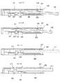
図1に示すように、先端部22の右端が係止突片部70の係止部71に係合した状態でさらに挿入すると、係止突片部70と一体のハートカム69が圧縮ばね32に抗して移動し、ロックピン31の先端がスタート点67から摺動溝65内を図の左回りに摺動する。第2のICカード12は、薄く、かつ、細幅部21を有するので、先端部22の左端はスペーサ28の当接部76に当接することなく、図5(a−2)のように、先端部22が傾斜面部75を擦りながら乗り上がる。スペーサ28は、スペーサ用ばね29によって押圧されているので、もとの位置から移動しない。第2のICカード12の先端部22がスペーサ28の上に乗り上がることで、電極20は第2カード用コンタクト27に適正な接触圧で接続される。第2のICカード12が挿入できる位置まで達すると、ロックピン31の一端部が摺動溝65の端部に達するので、押し込み力を抜くと、圧縮ばね32によりロック用スライダ30が戻されてロックピン31の一端部がピン係止凹部66に係止して第2のICカード12の挿入状態が保持される。
この挿入状態では、カード挿入孔36の付近で第2のICカード12の基端部がガイド板部57で下方に適正圧力で付勢されている。
このとき、図6(a)に示すように、第2のICカード12の細幅部21を過ぎた外側縁でスイッチ91の開閉端子33の接触可動片83が押し出されて開閉端子34の接触部86に接触して幅の狭い第2のICカード12を挿入した信号が出力される。
As shown in FIG. 1, when further inserted with the right end of the
In this inserted state, the base end portion of the
At this time, as shown in FIG. 6A, the contact
第2のICカード12を抜き取るときは、第2のICカード12を再度押し込むと、ロックピン31の一端部がピン係止凹部66から外れ、押し込み力を抜くと、他方の摺動溝65を通り元のスタート点67に戻って、図5(a−1)のように電極20と第2カード用コンタクト27の接続から外れる。同時に、接触可動片83と接触部86の接続から外れる。
When removing the
(1−2)第2のICカード12の異常(電極20が裏返し)状態での挿入
第2のICカード12を異常(電極20が下向きで、細幅部21が挿入方向右側)状態でICカード用コネクタのカード挿入口36へ挿入すると、第2のICカード12は、最初、ガイド板部57に案内されつつ両側の位置修正部58の間を通り抜けるが、図7(a)の異常時のように、細幅部21側が位置修正部58を通り、外側縁が位置修正部58に達し、細幅部21と反対側の先端部22がガイド部60に当接して第2のICカード12はそれ以上挿入することができない。
(1-2) Inserting the
(2−1)幅の広い第1のICカード11の正常(電極16が下向き)状態での挿入
第1のICカード11を正常(電極16が下向きで、狭幅の側縁部18が上向き)状態でICカード用コネクタのカード挿入口36へ挿入すると、第1のICカード11は、図5(b−1)及び図7(b)のように、誤挿入防止段部37に嵌合し、狭幅の側縁部18がガイド板部57に案内されつつ両側の位置修正部58の間を通り、また、広幅の側縁部17が位置修正部58の下を通り、図1のように、広幅の側縁部17の先端部22の右端が係止突片部70の係止部72に係合する。このとき、第1のICカード11は、厚いので内部は適正なクリアランスで移動する。
(2-1) Inserting the Wide
係合した状態で第1のICカード11をさらに挿入すると、係止突片部70と一体のハートカム69が圧縮ばね32に抗して移動し、ロックピン31の先端がスタート点67から摺動溝65内を図の左回りに摺動する。第1のICカード11は、厚く、かつ、第2のICカード12と異なり細幅部21を有しないので、先端部19の左端がスペーサ28の当接部76に当接しつつ、図5(b−2)のように、先端部19でスペーサ28を押しながらスペーサ用ばね29に抗してスペーサ28を押し込む。
この挿入状態では、カード挿入孔36の付近で第1のICカード11の基端部がガイド板部57で下方に適正圧力で付勢されている。
このとき、図6(b)に示すように、幅の広い第1のICカード11の広幅の側縁部17がスイッチ91の開閉端子33の接触可動片82を広げつつ第1のICカード11の正確な位置決めをしながらさらに挿入されると、広幅の側縁部17が開閉端子34の押圧部87に係合して可動片85を外側に逃げさせる。この状態で第1のICカード11の狭幅の側縁部18が開閉端子33の接触可動片83に接して接触可動片83が外側にやや移動するが、接触可動片83が押し出される前に接触部86がそれ以上に逃げており、接触可動片83が開閉端子34の接触部86に接触することはなく、幅の広い第1のICカード11を挿入しても信号が出力されない。
第1のICカード11をスペーサ28とともに移動することで、電極16は第1カード用コンタクト26に適正な接触圧で接続される。第1のICカード11が挿入できる位置まで達すると、ロックピン31の一端部が摺動溝65の端部に達するので、押し込み力を抜くと、圧縮ばね32によりロック用スライダ30が戻されてロックピン31の一端部がピン係止凹部66に係止して第1のICカード11の挿入状態が保持される。
When the
In this inserted state, the base end portion of the
At this time, as shown in FIG. 6B, the wide
By moving the
第1のICカード11を抜き取るときは、第1のICカード11を再度押し込むと、ロックピン31の一端部がピン係止凹部66から外れ、押し込み力を抜くと、圧縮ばね32により他方の摺動溝65を通りもとのスタート点67に戻って、図5(b−1)のように電極16と第1カード用コンタクト26の接続から外れる。
同時に、スペーサ28がスペーサ用ばね29によりもとの位置に戻され、また、開閉端子33と開閉端子34がもとの位置へ戻される。
When the
At the same time, the
(2−2)第1のICカード11の異常(電極16が裏返し)状態での挿入
第1のICカード11を異常(電極16が上向き)状態でICカード用コネクタのカード挿入口36へ挿入しようとすると、第1のICカード11の広幅の側縁部17と狭幅の側縁部18が逆のため、誤挿入防止段部37のあるカード挿入口36へ挿入することはできない。
(2-2) Inserting the
1…挿入終了判別端子、2…凸部、3…溝、4…挿入終了判別端子、15…凸部、6…ストッパ、10…ハウジング、11…第1のICカード、12…第2のICカード、13…カード挿入口、14…案内段差、15…ICコンタクト、16…電極、17…広幅の側縁部、18…狭幅の側縁部、19…先端部、20…電極、21…細幅部、22…先端部、23…切り欠き、24…切り欠き、25…ハウジング、26…第1カード用コンタクト、27…第2カード用コンタクト、28…スペーサ、29…スペーサ用ばね、30…ロック用スライダ、31…ロックピン、32…圧縮ばね、33…開閉端子、34…開閉端子、35…カバー、36…カード挿入口、37…誤挿入防止段部、38…底板部、39…コンタクト差し込み溝、40…背板部、41…コンタクト差し込み溝、42…天板部、43…切り欠き部、44…左側板部、45…端子挿入溝、46…端子挿入溝、47…右側板部、48…スライダ嵌合溝、49…ロックピン挿入孔、50…スライダ係合突部、51…スペーサガイド溝、52…ばね係合孔、53…係止突部、54…天板部、55…左側板部、56…右側板部、57…ガイド板部、58…位置修正部、59…ガイド部、60…ガイド部、61…逃げ孔、62…押圧ばね部、63…逃げ孔、64…切り溝、65…摺動溝、66…ピン係止凹部、67…スタート点、68…係合凹部、69…ハートカム、70…係止突片部、71…係止部、72…係止部、73…コンタクト受け部、74…ばね嵌合突部、75…傾斜面部、76…当接部、77…摺動突条部、78…ばね係止溝、79…両端部、80…中央部、81…係止片部、82…接触可動片、83…接触可動片、84…係止片部、85…可動片、86…接触部、87…押圧部、88…端子片、89…端子片、90…圧入片、91…スイッチ。
DESCRIPTION OF
Claims (5)
The distance between the contact portion of the fixed side open / close terminal that comes in contact with and separates from the contact movable piece of the movable side open / close terminal and the pressing portion formed by shifting the position from this contact portion is the wide side of the first IC card. 5. The IC card connector according to claim 4, wherein the connector is set to be sufficiently shorter than the distance between the edge and the side edge of the second IC card.
Priority Applications (2)
| Application Number | Priority Date | Filing Date | Title |
|---|---|---|---|
| JP2006191721A JP4699951B2 (en) | 2006-07-12 | 2006-07-12 | IC card connector |
| CN2007100055697A CN101106226B (en) | 2006-07-12 | 2007-02-12 | Connector for IC card |
Applications Claiming Priority (1)
| Application Number | Priority Date | Filing Date | Title |
|---|---|---|---|
| JP2006191721A JP4699951B2 (en) | 2006-07-12 | 2006-07-12 | IC card connector |
Publications (2)
| Publication Number | Publication Date |
|---|---|
| JP2008021510A JP2008021510A (en) | 2008-01-31 |
| JP4699951B2 true JP4699951B2 (en) | 2011-06-15 |
Family
ID=38999991
Family Applications (1)
| Application Number | Title | Priority Date | Filing Date |
|---|---|---|---|
| JP2006191721A Expired - Fee Related JP4699951B2 (en) | 2006-07-12 | 2006-07-12 | IC card connector |
Country Status (2)
| Country | Link |
|---|---|
| JP (1) | JP4699951B2 (en) |
| CN (1) | CN101106226B (en) |
Families Citing this family (2)
| Publication number | Priority date | Publication date | Assignee | Title |
|---|---|---|---|---|
| JP4978871B2 (en) * | 2009-11-18 | 2012-07-18 | Smk株式会社 | Board connector |
| JP5811365B2 (en) * | 2013-06-19 | 2015-11-11 | Smk株式会社 | Card connector with removal mechanism |
Citations (1)
| Publication number | Priority date | Publication date | Assignee | Title |
|---|---|---|---|---|
| JP2001351709A (en) * | 2000-06-02 | 2001-12-21 | D D K Ltd | Connector for memory card |
Family Cites Families (4)
| Publication number | Priority date | Publication date | Assignee | Title |
|---|---|---|---|---|
| JP3821648B2 (en) * | 2001-01-15 | 2006-09-13 | アルプス電気株式会社 | Card connector device |
| JP3949060B2 (en) * | 2003-01-08 | 2007-07-25 | アルプス電気株式会社 | Card connector device |
| JP4287673B2 (en) * | 2003-02-26 | 2009-07-01 | アルプス電気株式会社 | Card connector device |
| JP4023389B2 (en) * | 2003-05-26 | 2007-12-19 | 松下電工株式会社 | Memory card socket |
-
2006
- 2006-07-12 JP JP2006191721A patent/JP4699951B2/en not_active Expired - Fee Related
-
2007
- 2007-02-12 CN CN2007100055697A patent/CN101106226B/en not_active Expired - Fee Related
Patent Citations (1)
| Publication number | Priority date | Publication date | Assignee | Title |
|---|---|---|---|---|
| JP2001351709A (en) * | 2000-06-02 | 2001-12-21 | D D K Ltd | Connector for memory card |
Also Published As
| Publication number | Publication date |
|---|---|
| CN101106226A (en) | 2008-01-16 |
| CN101106226B (en) | 2011-01-26 |
| JP2008021510A (en) | 2008-01-31 |
Similar Documents
| Publication | Publication Date | Title |
|---|---|---|
| US6394827B2 (en) | Card connector | |
| US9001501B2 (en) | Card tray and tray connector | |
| WO2009131784A2 (en) | Push-type connector | |
| US8382498B2 (en) | Card connector with ejector | |
| JP4585963B2 (en) | Card connector | |
| US4185882A (en) | Electrical connector for printed circuit boards or the like | |
| CN103311002B (en) | Terminal and attachment structure thereof | |
| JP2004152623A (en) | Connector and contact structure of connector | |
| US20120329330A1 (en) | Card connector | |
| JP4778373B2 (en) | IC card connector | |
| US7192287B2 (en) | Card connector | |
| JP4576354B2 (en) | Card connector | |
| US20070202750A1 (en) | Card connector | |
| US9039440B2 (en) | Card connector | |
| JP4699951B2 (en) | IC card connector | |
| JP4023389B2 (en) | Memory card socket | |
| JP3101826U (en) | PC card adapter with elastic pin for lateral pressure | |
| KR101012891B1 (en) | Memory card socket | |
| JP3982371B2 (en) | Memory card connector device | |
| JP5605322B2 (en) | Card connector | |
| KR101012911B1 (en) | Socket for Memory Card | |
| CN102570184A (en) | Card connector | |
| JP3175424U (en) | Card connector device | |
| JP3945432B2 (en) | Memory card socket | |
| KR101586781B1 (en) | Connector for card |
Legal Events
| Date | Code | Title | Description |
|---|---|---|---|
| A621 | Written request for application examination |
Free format text: JAPANESE INTERMEDIATE CODE: A621 Effective date: 20090313 |
|
| A977 | Report on retrieval |
Free format text: JAPANESE INTERMEDIATE CODE: A971007 Effective date: 20110118 |
|
| A01 | Written decision to grant a patent or to grant a registration (utility model) |
Free format text: JAPANESE INTERMEDIATE CODE: A01 Effective date: 20110222 |
|
| A61 | First payment of annual fees (during grant procedure) |
Free format text: JAPANESE INTERMEDIATE CODE: A61 Effective date: 20110303 |
|
| LAPS | Cancellation because of no payment of annual fees |