JP4682527B2 - Fuel cell control device - Google Patents
Fuel cell control device Download PDFInfo
- Publication number
- JP4682527B2 JP4682527B2 JP2004117793A JP2004117793A JP4682527B2 JP 4682527 B2 JP4682527 B2 JP 4682527B2 JP 2004117793 A JP2004117793 A JP 2004117793A JP 2004117793 A JP2004117793 A JP 2004117793A JP 4682527 B2 JP4682527 B2 JP 4682527B2
- Authority
- JP
- Japan
- Prior art keywords
- hydrogen
- pressure
- fuel cell
- gas
- target
- Prior art date
- Legal status (The legal status is an assumption and is not a legal conclusion. Google has not performed a legal analysis and makes no representation as to the accuracy of the status listed.)
- Expired - Fee Related
Links
- 239000000446 fuel Substances 0.000 title claims description 111
- 239000001257 hydrogen Substances 0.000 claims description 355
- 229910052739 hydrogen Inorganic materials 0.000 claims description 355
- UFHFLCQGNIYNRP-UHFFFAOYSA-N Hydrogen Chemical compound [H][H] UFHFLCQGNIYNRP-UHFFFAOYSA-N 0.000 claims description 348
- 239000007789 gas Substances 0.000 claims description 157
- 230000001590 oxidative effect Effects 0.000 claims description 32
- 239000007800 oxidant agent Substances 0.000 claims description 31
- 238000007599 discharging Methods 0.000 claims description 6
- 238000001514 detection method Methods 0.000 claims description 3
- 210000004027 cell Anatomy 0.000 description 111
- 238000010248 power generation Methods 0.000 description 55
- 239000012535 impurity Substances 0.000 description 28
- XLYOFNOQVPJJNP-UHFFFAOYSA-N water Substances O XLYOFNOQVPJJNP-UHFFFAOYSA-N 0.000 description 23
- QVGXLLKOCUKJST-UHFFFAOYSA-N atomic oxygen Chemical compound [O] QVGXLLKOCUKJST-UHFFFAOYSA-N 0.000 description 16
- 239000001301 oxygen Substances 0.000 description 16
- 229910052760 oxygen Inorganic materials 0.000 description 16
- 238000000034 method Methods 0.000 description 15
- IJGRMHOSHXDMSA-UHFFFAOYSA-N Atomic nitrogen Chemical compound N#N IJGRMHOSHXDMSA-UHFFFAOYSA-N 0.000 description 14
- 239000002737 fuel gas Substances 0.000 description 13
- 239000012528 membrane Substances 0.000 description 12
- 239000003792 electrolyte Substances 0.000 description 10
- 230000001105 regulatory effect Effects 0.000 description 10
- 239000003054 catalyst Substances 0.000 description 9
- 238000009792 diffusion process Methods 0.000 description 8
- 230000001276 controlling effect Effects 0.000 description 7
- 239000002826 coolant Substances 0.000 description 7
- 150000002431 hydrogen Chemical class 0.000 description 7
- 229910052757 nitrogen Inorganic materials 0.000 description 7
- 238000012545 processing Methods 0.000 description 7
- 238000010586 diagram Methods 0.000 description 6
- 239000002828 fuel tank Substances 0.000 description 6
- 238000011144 upstream manufacturing Methods 0.000 description 6
- 210000005056 cell body Anatomy 0.000 description 5
- 239000000498 cooling water Substances 0.000 description 4
- 239000012466 permeate Substances 0.000 description 3
- 102220519085 Cytochrome P450 1A2_S18C_mutation Human genes 0.000 description 2
- 238000001816 cooling Methods 0.000 description 2
- 230000007423 decrease Effects 0.000 description 2
- 238000013461 design Methods 0.000 description 2
- VNWKTOKETHGBQD-UHFFFAOYSA-N methane Chemical compound C VNWKTOKETHGBQD-UHFFFAOYSA-N 0.000 description 2
- 238000012986 modification Methods 0.000 description 2
- 230000004048 modification Effects 0.000 description 2
- 239000005518 polymer electrolyte Substances 0.000 description 2
- 230000001133 acceleration Effects 0.000 description 1
- 230000004913 activation Effects 0.000 description 1
- 230000003197 catalytic effect Effects 0.000 description 1
- 239000004020 conductor Substances 0.000 description 1
- 238000012937 correction Methods 0.000 description 1
- 230000006866 deterioration Effects 0.000 description 1
- 239000007772 electrode material Substances 0.000 description 1
- 238000007710 freezing Methods 0.000 description 1
- 230000008014 freezing Effects 0.000 description 1
- 238000005259 measurement Methods 0.000 description 1
- 239000003345 natural gas Substances 0.000 description 1
- 102220057255 rs730881172 Human genes 0.000 description 1
- 239000002699 waste material Substances 0.000 description 1
Images


Classifications
-
- H—ELECTRICITY
- H01—ELECTRIC ELEMENTS
- H01M—PROCESSES OR MEANS, e.g. BATTERIES, FOR THE DIRECT CONVERSION OF CHEMICAL ENERGY INTO ELECTRICAL ENERGY
- H01M8/00—Fuel cells; Manufacture thereof
- H01M8/04—Auxiliary arrangements, e.g. for control of pressure or for circulation of fluids
- H01M8/04082—Arrangements for control of reactant parameters, e.g. pressure or concentration
- H01M8/04089—Arrangements for control of reactant parameters, e.g. pressure or concentration of gaseous reactants
- H01M8/04104—Regulation of differential pressures
-
- H—ELECTRICITY
- H01—ELECTRIC ELEMENTS
- H01M—PROCESSES OR MEANS, e.g. BATTERIES, FOR THE DIRECT CONVERSION OF CHEMICAL ENERGY INTO ELECTRICAL ENERGY
- H01M8/00—Fuel cells; Manufacture thereof
- H01M8/04—Auxiliary arrangements, e.g. for control of pressure or for circulation of fluids
- H01M8/04007—Auxiliary arrangements, e.g. for control of pressure or for circulation of fluids related to heat exchange
-
- H—ELECTRICITY
- H01—ELECTRIC ELEMENTS
- H01M—PROCESSES OR MEANS, e.g. BATTERIES, FOR THE DIRECT CONVERSION OF CHEMICAL ENERGY INTO ELECTRICAL ENERGY
- H01M8/00—Fuel cells; Manufacture thereof
- H01M8/04—Auxiliary arrangements, e.g. for control of pressure or for circulation of fluids
- H01M8/04298—Processes for controlling fuel cells or fuel cell systems
- H01M8/04313—Processes for controlling fuel cells or fuel cell systems characterised by the detection or assessment of variables; characterised by the detection or assessment of failure or abnormal function
- H01M8/0438—Pressure; Ambient pressure; Flow
- H01M8/04395—Pressure; Ambient pressure; Flow of cathode reactants at the inlet or inside the fuel cell
-
- H—ELECTRICITY
- H01—ELECTRIC ELEMENTS
- H01M—PROCESSES OR MEANS, e.g. BATTERIES, FOR THE DIRECT CONVERSION OF CHEMICAL ENERGY INTO ELECTRICAL ENERGY
- H01M8/00—Fuel cells; Manufacture thereof
- H01M8/04—Auxiliary arrangements, e.g. for control of pressure or for circulation of fluids
- H01M8/04298—Processes for controlling fuel cells or fuel cell systems
- H01M8/04694—Processes for controlling fuel cells or fuel cell systems characterised by variables to be controlled
- H01M8/04746—Pressure; Flow
- H01M8/04753—Pressure; Flow of fuel cell reactants
-
- H—ELECTRICITY
- H01—ELECTRIC ELEMENTS
- H01M—PROCESSES OR MEANS, e.g. BATTERIES, FOR THE DIRECT CONVERSION OF CHEMICAL ENERGY INTO ELECTRICAL ENERGY
- H01M8/00—Fuel cells; Manufacture thereof
- H01M8/04—Auxiliary arrangements, e.g. for control of pressure or for circulation of fluids
- H01M8/04298—Processes for controlling fuel cells or fuel cell systems
- H01M8/04313—Processes for controlling fuel cells or fuel cell systems characterised by the detection or assessment of variables; characterised by the detection or assessment of failure or abnormal function
- H01M8/0432—Temperature; Ambient temperature
-
- H—ELECTRICITY
- H01—ELECTRIC ELEMENTS
- H01M—PROCESSES OR MEANS, e.g. BATTERIES, FOR THE DIRECT CONVERSION OF CHEMICAL ENERGY INTO ELECTRICAL ENERGY
- H01M8/00—Fuel cells; Manufacture thereof
- H01M8/04—Auxiliary arrangements, e.g. for control of pressure or for circulation of fluids
- H01M8/04298—Processes for controlling fuel cells or fuel cell systems
- H01M8/04313—Processes for controlling fuel cells or fuel cell systems characterised by the detection or assessment of variables; characterised by the detection or assessment of failure or abnormal function
- H01M8/0444—Concentration; Density
- H01M8/04447—Concentration; Density of anode reactants at the inlet or inside the fuel cell
-
- H—ELECTRICITY
- H01—ELECTRIC ELEMENTS
- H01M—PROCESSES OR MEANS, e.g. BATTERIES, FOR THE DIRECT CONVERSION OF CHEMICAL ENERGY INTO ELECTRICAL ENERGY
- H01M8/00—Fuel cells; Manufacture thereof
- H01M8/04—Auxiliary arrangements, e.g. for control of pressure or for circulation of fluids
- H01M8/04298—Processes for controlling fuel cells or fuel cell systems
- H01M8/04313—Processes for controlling fuel cells or fuel cell systems characterised by the detection or assessment of variables; characterised by the detection or assessment of failure or abnormal function
- H01M8/0444—Concentration; Density
- H01M8/04462—Concentration; Density of anode exhausts
-
- H—ELECTRICITY
- H01—ELECTRIC ELEMENTS
- H01M—PROCESSES OR MEANS, e.g. BATTERIES, FOR THE DIRECT CONVERSION OF CHEMICAL ENERGY INTO ELECTRICAL ENERGY
- H01M8/00—Fuel cells; Manufacture thereof
- H01M8/04—Auxiliary arrangements, e.g. for control of pressure or for circulation of fluids
- H01M8/04298—Processes for controlling fuel cells or fuel cell systems
- H01M8/04694—Processes for controlling fuel cells or fuel cell systems characterised by variables to be controlled
- H01M8/04746—Pressure; Flow
- H01M8/04761—Pressure; Flow of fuel cell exhausts
-
- Y—GENERAL TAGGING OF NEW TECHNOLOGICAL DEVELOPMENTS; GENERAL TAGGING OF CROSS-SECTIONAL TECHNOLOGIES SPANNING OVER SEVERAL SECTIONS OF THE IPC; TECHNICAL SUBJECTS COVERED BY FORMER USPC CROSS-REFERENCE ART COLLECTIONS [XRACs] AND DIGESTS
- Y02—TECHNOLOGIES OR APPLICATIONS FOR MITIGATION OR ADAPTATION AGAINST CLIMATE CHANGE
- Y02E—REDUCTION OF GREENHOUSE GAS [GHG] EMISSIONS, RELATED TO ENERGY GENERATION, TRANSMISSION OR DISTRIBUTION
- Y02E60/00—Enabling technologies; Technologies with a potential or indirect contribution to GHG emissions mitigation
- Y02E60/30—Hydrogen technology
- Y02E60/50—Fuel cells
Landscapes
- Life Sciences & Earth Sciences (AREA)
- Engineering & Computer Science (AREA)
- Manufacturing & Machinery (AREA)
- Sustainable Development (AREA)
- Sustainable Energy (AREA)
- Chemical & Material Sciences (AREA)
- Chemical Kinetics & Catalysis (AREA)
- Electrochemistry (AREA)
- General Chemical & Material Sciences (AREA)
- Fuel Cell (AREA)
Description
本発明は、燃料電池の制御装置に関する。 The present invention relates to a control device for a fuel cell.
固体高分子形の燃料電池は、電解質膜、電解質膜を挟んで形成される2つの触媒層、および2つの触媒層の外側に形成される1対の拡散層を有している。燃料電池では、一方の拡散層には、水素を含む燃料ガスが供給され、他方の拡散層には、酸素を含む酸化剤ガスが供給される。燃料ガスが供給される拡散層は、水素極またはアノードと呼ばれ、酸化剤ガスが供給される拡散層は空気極またはカソードと呼ばれる。 The polymer electrolyte fuel cell has an electrolyte membrane, two catalyst layers formed with the electrolyte membrane sandwiched therebetween, and a pair of diffusion layers formed outside the two catalyst layers. In a fuel cell, one diffusion layer is supplied with a fuel gas containing hydrogen, and the other diffusion layer is supplied with an oxidant gas containing oxygen. The diffusion layer to which the fuel gas is supplied is called a hydrogen electrode or an anode, and the diffusion layer to which the oxidant gas is supplied is called an air electrode or a cathode.
水素極に供給された水素は、触媒層を拡散し、触媒層においてプロトンと電子に分離される。プロトンは、水分子とともに電解質膜を通って陽極側の触媒層に移動する。 The hydrogen supplied to the hydrogen electrode diffuses in the catalyst layer and is separated into protons and electrons in the catalyst layer. Protons move together with water molecules through the electrolyte membrane to the catalyst layer on the anode side.
一方、空気極に供給された酸素は、触媒層を拡散する。そして、空気極側の触媒層において、プロトン、電子、および酸素が反応して水が生成される。このとき、空気極と水素極とを外部回路(例えば、導体)で接続すると、水素極から陽空気極に電子が移動し、上記のプロトンとの反応に消費される。 On the other hand, oxygen supplied to the air electrode diffuses in the catalyst layer. Then, in the catalyst layer on the air electrode side, protons, electrons, and oxygen react to generate water. At this time, when the air electrode and the hydrogen electrode are connected by an external circuit (for example, a conductor), electrons move from the hydrogen electrode to the positive air electrode and are consumed for the reaction with the protons.
燃料電池において、発電量を増加するには、空気極と水素極のそれぞれに発電量に応じた酸化剤ガスおよび燃料ガスを供給する必要がある。そして、酸化剤ガスとしては、一般的には、空気が使用される。 In a fuel cell, in order to increase the power generation amount, it is necessary to supply an oxidant gas and a fuel gas corresponding to the power generation amount to each of the air electrode and the hydrogen electrode. In general, air is used as the oxidant gas.
しかし、空気は、酸素と窒素を含んでいる。窒素は、空気極側の反応には使用されないため、空気極側の空間に滞留するとともに、拡散層および電解質膜を拡散して水素極側まで透過する。また、空気極側では、プロトンと電子と酸素の反応により水が生成される。この空気極側の生成水も、拡散層および電解質膜を拡散して水素極側まで透過する。このため、燃料電池を長時間運転すると、燃料電池内の水素極側の空間において、水素以外の窒素、水蒸気等の不純物濃度が増加する。 However, air contains oxygen and nitrogen. Since nitrogen is not used for the reaction on the air electrode side, it stays in the space on the air electrode side and diffuses through the diffusion layer and the electrolyte membrane to permeate to the hydrogen electrode side. On the air electrode side, water is generated by the reaction of protons, electrons, and oxygen. The generated water on the air electrode side also diffuses through the diffusion layer and the electrolyte membrane and permeates to the hydrogen electrode side. For this reason, when the fuel cell is operated for a long time, the concentration of impurities such as nitrogen and water vapor other than hydrogen increases in the space on the hydrogen electrode side in the fuel cell.
水素極側で水素以外の不純物濃度が増加すると、水素濃度が増加しにくく、発電量を増加しにくい状態となる。そのため、従来の固体高分子形の燃料電池では、水素極側で反応後の燃料ガス(以下、燃料オフガスという)を排出するため、水素極の燃料ガスの流路下流側に排出弁が設けられていた。 When the concentration of impurities other than hydrogen increases on the hydrogen electrode side, the hydrogen concentration is unlikely to increase and the amount of power generation is unlikely to increase. Therefore, in a conventional polymer electrolyte fuel cell, a discharge valve is provided on the downstream side of the fuel gas flow path of the hydrogen electrode in order to discharge the fuel gas after the reaction on the hydrogen electrode side (hereinafter referred to as fuel off gas). It was.
この排出弁は、例えば、燃料電池の起動時に開弁され、水素極側の不純物ガスを排出させ、水素極側の水素濃度を高めるために使用されていた(例えば、特許文献1参照)。 This discharge valve is opened, for example, when the fuel cell is started, and is used to discharge the impurity gas on the hydrogen electrode side and increase the hydrogen concentration on the hydrogen electrode side (see, for example, Patent Document 1).
また、燃料電池の起動後は、排出弁は、所定のシーケンスにしたがって、開閉され、水素極側の不純物を排出し、発電量を維持していた。 In addition, after the fuel cell is started, the discharge valve is opened and closed according to a predetermined sequence, and impurities on the hydrogen electrode side are discharged to maintain the power generation amount.
しかし、起動時に排出弁の開閉により不純物を排出し、水素濃度を高める方式では、低温下で排出弁が凍結した場合には、凍結した排出弁を解凍するための時間を要し、短時間での起動ができない。また、運転中に排出弁を開閉し、発電量を維持する方式では、不純物とともに水素が排出されてしまう場合があり、燃料効率が必ずしもよくない。
本発明の目的は、水素極側の排出弁の開閉によらず、発電量を増加させ、または、所望の発電量を維持する燃料電池を提供することにある。 An object of the present invention is to provide a fuel cell that increases the power generation amount or maintains a desired power generation amount regardless of opening and closing of the discharge valve on the hydrogen electrode side.
本発明は前記課題を解決するために、以下の手段を採用した。すなわち、本発明は、燃料電池の制御装置において、燃料電池の酸化剤ガス供給通路を通じてカソードに酸化剤ガスを供給する酸化剤ガス供給手段と、上記酸化剤ガス供給通路または上記カソード内のガス圧力を検出するカソード側ガス圧力検出手段と、燃料電池の水素供給通路を通じてアノードに水素を供給する水素供給手段と、上記水素供給通路または上記アノード内のガス圧力に占める水素の圧力に係る目標水素分圧を決定する手段と、上記カソード側ガス圧力検出手段により検出されたガス圧力と上記目標水素分圧とに基づいて燃料電池に供給される水素の水素供給圧力を算出する水素供給圧力算出手段と、上記水素供給圧力にて上記水素供給手段から燃料電池に水素を供給する水素供給制御手段と、を備えたことを特徴とする。 The present invention employs the following means in order to solve the above problems. That is, the present invention relates to an oxidant gas supply means for supplying an oxidant gas to the cathode through an oxidant gas supply passage of the fuel cell, and a gas pressure in the oxidant gas supply passage or the cathode in the fuel cell control device. Cathode-side gas pressure detection means for detecting hydrogen, hydrogen supply means for supplying hydrogen to the anode through the hydrogen supply passage of the fuel cell, and target hydrogen content relating to the pressure of hydrogen in the gas pressure in the hydrogen supply passage or the anode Means for determining pressure, and hydrogen supply pressure calculation means for calculating the hydrogen supply pressure of hydrogen supplied to the fuel cell based on the gas pressure detected by the cathode gas pressure detection means and the target hydrogen partial pressure, And hydrogen supply control means for supplying hydrogen to the fuel cell from the hydrogen supply means at the hydrogen supply pressure.
この燃料電池の制御装置は、燃料電池に酸化剤ガスを供給する酸化剤ガス供給通路または上記カソード内でガス圧力を検出し、そのガス圧力と目標水素分圧とに基づいて水素供給圧力を算出し、そのような水素供給圧力でアノードに水素を供給する。酸化剤ガス供給通路または上記カソード内のガスがアノード側に漏れてくると想定すると、上記水素供給圧力で水素を供給することによってアノード側の水素分圧を上記目標水素分圧に制御することができる。この場合、アノード側でガスを排出するための排出弁を使用する頻度を低減し、または、使用することなく燃料電池を制御できる。また、そのような排出弁を設ける必要をなくすることができる。 The fuel cell control device detects a gas pressure in an oxidant gas supply passage for supplying an oxidant gas to the fuel cell or in the cathode, and calculates a hydrogen supply pressure based on the gas pressure and a target hydrogen partial pressure. Then, hydrogen is supplied to the anode at such a hydrogen supply pressure. Assuming that the gas in the oxidant gas supply passage or the cathode leaks to the anode side, the hydrogen partial pressure on the anode side can be controlled to the target hydrogen partial pressure by supplying hydrogen at the hydrogen supply pressure. it can. In this case, the frequency of using a discharge valve for discharging gas on the anode side can be reduced or the fuel cell can be controlled without using it. Moreover, it is not necessary to provide such a discharge valve.
さらに、上記燃料電池の発電量が多くなるほど上記酸化剤ガス供給手段により供給される酸化剤ガスの供給量を多くする酸化剤ガス量制御手段を備えてもよい。このような構成により、発電量に応じて、酸化ガス量、カソード側のガス圧力、およびアノード側の目標水素分圧が決定されるので、発電量に応じた水素供給圧力が算出できる。 Furthermore, an oxidant gas amount control unit that increases the supply amount of the oxidant gas supplied by the oxidant gas supply unit as the power generation amount of the fuel cell increases may be provided. With such a configuration, the amount of oxidizing gas, the gas pressure on the cathode side, and the target hydrogen partial pressure on the anode side are determined according to the amount of power generation, so that the hydrogen supply pressure corresponding to the amount of power generation can be calculated.
さらに、上記燃料電池の温度を検出する燃料電池温度検出手段と、上記燃料電池の温度より上記目標水素分圧を補正する手段とを備え、上記水素供給圧力算出手段は、上記カソード側ガス圧力検出手段により検出されたガス圧力と上記補正された目標水素分圧とに基づいて上記燃料電池に供給される水素の水素供給圧力を算出するようにしてもよい。このような構成により、アノード側を燃料電池の温度で補正された水素分圧に制御でき、発電量および温度に応じた適正な量の水素を供給できる。 Furthermore, the fuel cell temperature detecting means for detecting the temperature of the fuel cell, and means for correcting the target hydrogen partial pressure based on the temperature of the fuel cell, the hydrogen supply pressure calculating means is configured to detect the cathode side gas pressure. The hydrogen supply pressure of hydrogen supplied to the fuel cell may be calculated based on the gas pressure detected by the means and the corrected target hydrogen partial pressure. With such a configuration, the anode side can be controlled to a hydrogen partial pressure corrected by the temperature of the fuel cell, and an appropriate amount of hydrogen according to the amount of power generation and temperature can be supplied.
さらに、アノード内または水素供給通路に残留する残留ガスを排出する排出手段と、上記水素供給圧力がアノード側のガス圧力の許容範囲にないときに前記排出手段によって前記滞留ガスを排出させる排出制御手段と、残留ガスを排出させたときのアノード内または水素供給通路に残留する残留ガス分圧を算出する手段と、を備え、水素供給圧力算出手段は、上記残留ガス分圧と上記目標水素分圧とに基づいて上記燃料電池に供給される水素の水素供給圧力を算出するようにしてもよい。 Further, a discharge means for discharging the residual gas remaining in the anode or in the hydrogen supply passage, and a discharge control means for discharging the staying gas by the discharge means when the hydrogen supply pressure is not within the allowable range of the gas pressure on the anode side. And means for calculating a residual gas partial pressure remaining in the anode or in the hydrogen supply passage when the residual gas is discharged, wherein the hydrogen supply pressure calculating means includes the residual gas partial pressure and the target hydrogen partial pressure. Based on the above, the hydrogen supply pressure of the hydrogen supplied to the fuel cell may be calculated.
このような構成により、算出された水素供給圧力がアノード側のガス圧力の許容範囲にない場合には、アノード内または水素供給通路に残留する残留ガスを排出し、残留ガスのガス圧力を低下させ、低下した残留ガスのガス圧力と目標水素分圧に基づいて水素供給圧力を算出できる。したがって、そのような低下したガス圧力により、アノード側のガス圧力の許容範囲で水素供給圧力を算出でき、アノード側のガス圧力の許容範囲で燃料電池を制御できる。 With such a configuration, when the calculated hydrogen supply pressure is not within the allowable range of the gas pressure on the anode side, the residual gas remaining in the anode or in the hydrogen supply passage is discharged, and the gas pressure of the residual gas is reduced. The hydrogen supply pressure can be calculated based on the gas pressure of the lowered residual gas and the target hydrogen partial pressure. Therefore, the hydrogen supply pressure can be calculated within the allowable range of the gas pressure on the anode side by such a reduced gas pressure, and the fuel cell can be controlled within the allowable range of the gas pressure on the anode side.
本発明によれば、燃料電池において、水素極側の排出弁の開閉によらず、または、水素極側に排出弁を設けることなく、発電量を増加させ、または、所望の発電量を維持することができる。 According to the present invention, in a fuel cell, the power generation amount is increased or the desired power generation amount is maintained without opening or closing the discharge valve on the hydrogen electrode side or without providing a discharge valve on the hydrogen electrode side. be able to.
以下、図面を参照して本発明を実施するための最良の形態(以下、実施形態という)に係る燃料電池について説明する。以下の実施形態の構成は例示であり、本発明は実施形態の構成に限定されない。 Hereinafter, a fuel cell according to the best mode for carrying out the present invention (hereinafter referred to as an embodiment) will be described with reference to the drawings. The configuration of the following embodiment is an exemplification, and the present invention is not limited to the configuration of the embodiment.
<燃料電池の構成>
図1に、本発明の実施形態に係る燃料電池の構成図を示す。この燃料電池は、燃料電池本体1と、燃料電池本体1の空気極(カソードともいう)に酸化剤ガスである空気を供給する空気供給器7と、空気供給器7の上流側の空気導入通路に設置された大気圧センサ9と、空気極側のガス圧力を測定する空気極圧力センサ11と、空気極側のガス圧力を調整する調圧弁15と、燃料電池本体1の水素極(アノードともいう)に燃料ガスである水素を供給する燃料タンク5と、燃料タンク5からの水素の供給圧力を制御する水素供給弁13と、水素極からの燃料オフガスの排出を制御する排出弁17と、燃料電池本体1を冷却する冷却水の水温を検知する水温センサ19とを有している。
<Configuration of fuel cell>
FIG. 1 shows a configuration diagram of a fuel cell according to an embodiment of the present invention. This fuel cell includes a fuel cell
燃料電池本体1は、膜−電極接合体(MEA:Membrane-Electrode Assembly )とセパレータとを含むセルを直列に接続し、複数階層に積層した積層体(セルスタックと呼ばれる)から構成される。膜−電極接合体は、水素をプロトンと電子に分離する水素極と、水素極で生成されたプロトンを空気極に伝導する電解質膜と、空気極に伝導したプロトンと酸素と外部回路を通じて水素極から伝導した電子により水を生成する空気極とを含む。
The fuel cell
セパレータには、セル内の空気極に酸化剤ガスである空気を供給するための空気通路が設けられている。空気は、セル内でこの空気通路を上流から下流に流れるとともに空気極内を膜方向に拡散し、空気極内でプロトンと反応する。したがって、セル内の空気通路中、上流から下流に向かって徐徐に酸素密度は低下する。 The separator is provided with an air passage for supplying air, which is an oxidant gas, to the air electrode in the cell. Air flows through the air passage from upstream to downstream in the cell, diffuses in the air electrode in the film direction, and reacts with protons in the air electrode. Therefore, in the air passage in the cell, the oxygen density gradually decreases from upstream to downstream.
また、セパレータには、セル内の水素極に燃料ガスである水素を供給するための水素通路が設けられている。水素は、セル内でこの水素通路を上流から下流に流れるとともに水素極内を膜方向に拡散し、水素極内の触媒作用でプロトンになり、プロトンは、膜を透過して空気極に移動する。したがって、セル内の水素通路中、上流から下流に向かって徐徐に水素密度は低下する。 Further, the separator is provided with a hydrogen passage for supplying hydrogen as a fuel gas to the hydrogen electrode in the cell. Hydrogen flows through the hydrogen passage from the upstream to the downstream in the cell and diffuses in the hydrogen electrode in the direction of the membrane, and becomes a proton by the catalytic action in the hydrogen electrode, and the proton passes through the membrane and moves to the air electrode. . Therefore, in the hydrogen passage in the cell, the hydrogen density gradually decreases from upstream to downstream.
空気供給装置7(酸化剤ガス供給手段に相当する)は、例えば、エアコンプレッサであり、大気中の空気を加圧し、空気供給経路L1を通じて燃料電池本体1の空気極(上記セル内の空気通路)に供給する。空気供給器7から空気供給経路L1に供給される空気の流量はECU3からの制御信号により制御される。なお、大気圧は、空気供給器7の上流側の空気導入通路に設けられた大気圧センサ9により測定される。
The air supply device 7 (corresponding to the oxidant gas supply means) is, for example, an air compressor, pressurizes air in the atmosphere, and passes through the air supply path L1 to the air electrode of the fuel cell main body 1 (the air passage in the cell). ). The flow rate of air supplied from the
燃料電池本体1の空気極の下流側では、上記空気通路の出口にガス排出経路L2が接続され、このガス排出経路L2には調圧弁15が設けられている。この調圧弁15によって空気極側のガスの排出が制御される。また、ガス排出経路L2には、空気極側のガス圧力を測定する空気極圧力センサ11(カソード側ガス圧力検出手段に相当する)が設けられている。燃料電池本体1の空気極は、空気供給器7から空気を供給されるとともに、調圧弁15により、所定のガス圧力に制御される。空気供給器7の出口側の空気供給経路L1、燃料電池本体1の空気極(セル内の空気通路)、およびガス排出経路L2の調圧弁15に至る空間が本発明の酸化剤ガス給通路に相当する。
On the downstream side of the air electrode of the
燃料タンク5(水素供給手段に相当)は、水素供給経路L3上の水素供給弁13を介して燃料電池本体1の水素極側(上記セル内の水素通路)に水素を供給する。燃料タンク5は、水素を高圧状態(1気圧を超える圧力状態)で保持している。
The fuel tank 5 (corresponding to hydrogen supply means) supplies hydrogen to the hydrogen electrode side (hydrogen passage in the cell) of the fuel cell
水素供給弁13(水素供給制御手段に相当する)は、弁の開閉動作の制御により通過するガス流量を調整する。ここで、弁の開閉動作とは、例えば、開弁周期、開弁時間、あるいは閉弁時間等である。ただし、水素供給弁13は、弁の移動による開口部の開度の変更により燃料ガスの供給を制御するものであってもよい。
The hydrogen supply valve 13 (corresponding to a hydrogen supply control means) adjusts the gas flow rate that passes by controlling the opening / closing operation of the valve. Here, the opening / closing operation of the valve is, for example, a valve opening cycle, a valve opening time, or a valve closing time. However, the
燃料電池本体1の水素極の下流側では、上記セル内の水素通路の出口にガス排出経路L4が接続され、このガス排出経路L4には排出弁17(排出手段に相当する)が設けられている。排出弁17も、弁の開閉動作の制御により通過するガス流量を調整する。ただし、排出弁13は、弁の移動による開口部の開度の変更により排出ガスの流量を制御するものであってもよい。
A gas discharge path L4 is connected to the outlet of the hydrogen passage in the cell on the downstream side of the hydrogen electrode of the fuel cell
水素が供給される前(例えば、燃料電池の起動前)、水素極側には、膜−電極接合体を透過した空気(主として窒素)あるいは空気極で生成された生成水(水蒸気または液滴)が支配的に存在する。以下、このような窒素、水蒸気等を不純物ガスという。本実施形態の燃料電池は、水素供給前、水素極側の不純物ガスのガス圧力は概ね空気極側のガス圧力と同等であると仮定して水素供給弁13から供給すべき水素の供給圧力を決定する。
Before hydrogen is supplied (for example, before the start of the fuel cell), on the hydrogen electrode side, air that has permeated the membrane-electrode assembly (mainly nitrogen) or generated water (water vapor or droplets) generated at the air electrode Exist dominantly. Hereinafter, such nitrogen and water vapor are referred to as impurity gases. In the fuel cell of this embodiment, the hydrogen supply pressure to be supplied from the
ここで、水素供給圧力とは、水素供給弁13によって水素極内および水素極に接続される水素供給経路L3に供給される水素の圧力をいい、水素極内は、この水素供給圧力とバランスする圧力のガス(不純物ガスと水素の混合ガス)で満たされることになる。例えば、燃料タンク5に50気圧の水素が充填され、水素供給弁13が2気圧まで減圧して水素を水素供給経路L3に供給する場合と考える。そして、水素供給前に不純物ガスのガス圧力が1気圧であったと仮定する。この場合、2気圧の水素供給圧力で水素が供給され、水素極内は2気圧の混合ガスで満たされることになる。また、不純物ガスの分圧が1気圧に、水素の分圧が1気圧になる。
Here, the hydrogen supply pressure means the pressure of hydrogen supplied to the hydrogen supply path L3 connected to the inside of the hydrogen electrode and the hydrogen electrode by the
また、燃料電池の運転中、本実施形態の燃料電池は、水素極側に存在する水素による分圧と空気極側のガス圧力とによって水素極側のガス圧力(全体の圧力)が構成されると想定し、水素の供給圧力を制御する。水素供給弁13の出口側の水素供給経路L3、燃料電池本体1の水素極(セル内の水素通路)、およびガス排出経路L4の排出弁17に至る空間が本発明の水素供給通路に相当する。
In addition, during operation of the fuel cell, the fuel cell of the present embodiment is configured such that the gas pressure (total pressure) on the hydrogen electrode side is constituted by the partial pressure of hydrogen present on the hydrogen electrode side and the gas pressure on the air electrode side. Assuming that, the supply pressure of hydrogen is controlled. The space from the hydrogen supply path L3 on the outlet side of the
水温センサ19は、燃料電池本体1内のセルスタックを冷却する冷却水の水温を測定する。
The
ECU3は、CPU、メモリ、入出力インターフェース等を含み、本実施形態の燃料電
池の反応を制御する。ECU3は、不図示の入出力インターフェースを介して水素供給弁13、空気調圧弁15、および排出弁17の開閉または弁の開口の開度を制御する。また、ECU3は、空気供給器7から供給される空気の流量を制御する。さらに、ECU3は、大気圧センサ9、空気極圧力センサ11および水温センサ19(燃料電池温度検出手段に相当する)に接続され、大気圧、空気極内のガス圧力および冷却水の水温を監視する。
The
燃料電池の起動時、ECU3は、燃料電池が安定的に発電を持続するために必要な水素分圧である安定発電目標水素分圧をメモリ上の所定記憶領域から参照する(この処理を実行するECU3が目標水素分圧を決定する手段に相当する)。安定発電目標水素分圧は、燃料電池の仕様、寸法等から事前に実験値または設計値として決定され、ECU3のメモリに保持されている。
When starting the fuel cell, the
また、本燃料電池では、ECU3は、起動時の空気極圧力を大気圧に設定する。そして、ECU3は、空気極側のガス圧力と上記安定発電目標水素分圧とから目標水素圧力を算出する。本実施形態では、ECU3は、空気極のガス圧力が概ね水素供給前の水素極側の不純物ガスの圧力であると仮定する。そして、この空気極のガス圧力と安定発電目標水素分圧を加算した圧力を目標水素圧力として算出する(この処理を実行するECU3が水素供給圧力算出手段に相当する)。
Moreover, in this fuel cell, ECU3 sets the air electrode pressure at the time of starting to atmospheric pressure. Then, the
そして、ECU3は、水素供給弁13を開閉制御し、水素極側に供給する水素の供給圧力を目標水素圧力に制御する。その結果、目標水素圧力から水素極側の不純物ガスの圧力を除いた分圧の水素、すなわち、安定発電目標水素分圧の水素が水素極に供給される。このように、本実施形態の燃料電池では、主として、水素供給時の水素供給圧力の制御により、極力排出弁17を開閉せずに、水素極に燃料ガスである水素を供給する。
The
燃料電池の起動後、ECU3は、要求発電量と目標水素分圧の関係を示すマップから要求発電量に対応する水素分圧を参照する(この処理を実行するECU3が目標水素分圧を決定する手段に相当する)。
After starting the fuel cell, the
図2は、目標水素分圧を算出するマップの概念図である。ECU3は、要求発電量が与えられたときに、その発電量に必要な水素分圧を算出する際にこのマップを使用する。図2のマップでは、横軸が要求発電量であり、縦軸がその要求発電量を得るために必要な目標水素分圧(単位は、例えば、キロパスカル)である。複数のガスを含む混合ガスでは、概ね、各ガスの分圧応じて、各ガスの濃度が決まる。
FIG. 2 is a conceptual diagram of a map for calculating the target hydrogen partial pressure. When the required power generation amount is given, the
このようなマップは、燃料電池の仕様(例えば、触媒の密度、セルスタックの数、電極の材質等)ごとに、実測にて設定できる。図2に示すように、要求発電量と目標水素分圧の関係を示すマップは、一般的には右上がり、すなわち、要求発電量の増加とともに目標水素分圧も増加するグラフとなる。ECU3は、このようなマップを要求発電量値と目標水素分圧値とを複数組み合わせて構成されるテーブルとしてメモリに保持する。ただし、ECU3は、要求発電量値と目標水素分圧値との関係を実験式(例えば、1次直線、または2次以上の高次の曲線)として保持してもよい。なお、空気極のガス圧力を求めるためのマップ、空気極への空気供給量を求めるためのマップも同様の構成である。
Such a map can be set by actual measurement for each fuel cell specification (for example, catalyst density, number of cell stacks, electrode material, etc.). As shown in FIG. 2, the map showing the relationship between the required power generation amount and the target hydrogen partial pressure is generally a graph that increases to the right, that is, the target hydrogen partial pressure increases as the required power generation amount increases. The
また、ECU3は、要求発電量と酸素供給量との関係を示すマップから要求発電量に対応する酸素供給量を参照する。ECU3は、その酸素供給量の酸素を空気供給器7からの空気で供給する(この処理を実行するECU3が酸化剤ガス量制御手段に相当する)。さらに、ECU3は、要求発電量と空気極のガス圧力との関係を示すマップから要求発電量に対応するガス圧力を参照する。そして、ECU3は、空気極のガス圧力を調圧弁15の開閉により制御する。
Further, the
さらに、ECU3は、空気極のガス圧力が概ね水素極側の不純物ガスの圧力になると仮定し、空気極のガス圧力と目標水素分圧から目標水素圧力を決定する(この処理を実行するECU3が水素供給圧力算出手段に相当する)。そして、ECU3は、水素供給弁13を開閉制御し、水素極内に供給される水素の供給圧力を目標水素圧力に制御する。このように、本実施形態の燃料電池では、起動後も、主として、水素供給圧力の制御により、極力排出弁17を開閉せずに、水素極に燃料ガスである水素を供給する。
Further, the
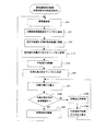
<制御フロー>
図3は、燃料電池起動時のECU3の制御を示すフローチャートである。この処理は、ECU3のCPUで実行される制御プログラムとして実現できる。本燃料電池では、起動時、ECU3は、まず、安定発電目標水素分圧を参照する(S1)。次に、ECU3は、空気極および水素供給前の水素極が大気圧にあると仮定して、大気圧と安定発電目標水素分圧から目標水素圧力を算出する(S3)。ここでは、大気圧と安定発電目標水素分圧との加算値を目標水素圧力とする。
<Control flow>
FIG. 3 is a flowchart showing the control of the
次に、ECU3は、水素供給弁13を制御して、目標水素圧力の水素を水素極に供給する(S5)。次に、空気調圧弁15を制御し、空気極を大気圧に設定する。このような制御の結果、水素極側の水素分圧は、安定発電目標水素分圧に制御される。そして、ECU3は、燃料電池を起動する(S9)。
Next, the
なお、ここでは、起動時に空気極を大気圧になるように制御したが、本発明の実施は、このような手順に限定されるものではない。すなわち、起動時に空気極を大気圧にすること自体は必須の手順ではない。 Here, the air electrode is controlled to be atmospheric pressure at the time of startup, but the implementation of the present invention is not limited to such a procedure. That is, it is not an essential procedure to bring the air electrode to atmospheric pressure at the time of startup.
図4は、通常運転時のECU3の制御を示すフローチャートである。この処理も、ECU3のCPUで実行される制御プログラムとして実現できる。通常運転状態では、まず、ECU3は要求発電量を算出する(S10)。要求発電量は、ユーザからの指示、例えば、車両のアクセルに対応する加速指示値、この燃料電池から電力を供給される家庭、施設、機器等における電力使用量の履歴等から算出される。
FIG. 4 is a flowchart showing control of the
次に、ECU3は、要求発電量を基にマップを参照し、目標空気供給量を決定する(S11)。この目標空気供給量は、発電量に応じて必要な酸素量に対応する。次に、ECU3は、空気供給器7の空気供給量を目標空気供給量に制御する(S12)。
Next, the
次に、ECU3は、要求発電量を基にマップを参照し、空気極の目標ガス圧力を決定する(S13)。次に、ECU3は、調圧弁15を制御し、空気極のガス圧力を目標ガス圧力に制御する(S14)。
Next, the
次に、ECU3は、要求発電量を基にマップを参照し、水素極の目標水素分圧を決定する(S15)。この目標水素分圧は、発電量に応じて必要な水素極側の水素濃度に対応する量である。次に、ECU3は、空気極の目標ガス圧力と水素極の目標水素分圧から目標水素圧力を算出する(S17)。本実施形態では、空気極の目標ガス圧力に目標水素分圧を加算した値を目標水素圧力とする。
Next, the
そして、ECU3は、水素供給弁13を制御して、目標水素圧力の水素を水素極に供給する(S19)。このような制御の結果、水素極側の水素分圧は、目標水素分圧に制御される。そして、ECU3は、制御をS11に戻す。
Then, the
以上述べたように、本実施形態の燃料電池によれば、燃料電池の起動時、安定発電目標
水素分圧と空気極のガス圧力とにより目標水素圧力を算出し、水素極に供給される水素の供給圧力を目標水素圧力に制御する。その結果、水素極の水素分圧を概ね安定発電目標水素分圧に制御でき、安定起動に必要な水素を水素極に供給できる。
As described above, according to the fuel cell of the present embodiment, when the fuel cell is started, the target hydrogen pressure is calculated from the stable power generation target hydrogen partial pressure and the gas pressure of the air electrode, and the hydrogen supplied to the hydrogen electrode is calculated. Is controlled to a target hydrogen pressure. As a result, the hydrogen partial pressure of the hydrogen electrode can be generally controlled to the stable power generation target hydrogen partial pressure, and hydrogen necessary for stable startup can be supplied to the hydrogen electrode.
このように、本実施形態の燃料電池では、起動時に水素供給圧力の制御により水素極側の水素分圧、したがって、水素濃度を制御できる。したがって、従来の燃料電池のように、起動時に排出弁17を開弁して、水素極内の不純物ガスを排出する必要がない。このため、例えば、氷点下で排出弁17が凍結した場合でも、短時間で燃料電池を起動できる。
Thus, in the fuel cell of the present embodiment, the hydrogen partial pressure on the hydrogen electrode side, and hence the hydrogen concentration, can be controlled by controlling the hydrogen supply pressure at the time of startup. Therefore, unlike the conventional fuel cell, it is not necessary to open the
また、本実施形態の燃料電池によれば、起動時に、空気極のガス圧力を大気圧に制御する。空気極に供給された空気のうち、酸素は、燃料電池の反応に使用され、窒素等の不純物が拡散層および電解質膜を水素極側に透過する。したがって、空気圧を大気圧とすることにより、空気極を大気圧以上に加圧する場合と比較して、水素極側の不純物ガスの分圧を低下することができ、制御すべき目標水素圧力を実質的に低く設定できる。 Moreover, according to the fuel cell of this embodiment, the gas pressure of the air electrode is controlled to atmospheric pressure at the time of startup. Of the air supplied to the air electrode, oxygen is used for the reaction of the fuel cell, and impurities such as nitrogen permeate the diffusion layer and the electrolyte membrane to the hydrogen electrode side. Therefore, by setting the air pressure to atmospheric pressure, the partial pressure of the impurity gas on the hydrogen electrode side can be reduced compared with the case where the air electrode is pressurized to atmospheric pressure or higher, and the target hydrogen pressure to be controlled is substantially reduced. Can be set low.
また、本実施形態の燃料電池によれば、通常運転時には、発電量に基づく、目標水素分圧と空気極のガス圧力とに基づき目標水素圧力を算出し、その目標水素圧力での水素を供給する。このような制御により、本実施形態の燃料電池は、要求発電量に対応する目標水素分圧したがって目標水素濃度の水素を水素極に供給する。したがって、本実施形態の燃料電池では、通常運転時に排出弁17を開閉する必要がない。このため、排出弁17の開閉による無駄な水素の排出を低減することができる。また、排出弁17が故障した場合に、上記図3および図4に示した制御により燃料電池の起動、および運転の継続ができる。さらに、このような制御を実現することにより、排出弁17自体を省略した構成の燃料電池とすることもできる。
Further, according to the fuel cell of this embodiment, during normal operation, the target hydrogen pressure is calculated based on the target hydrogen partial pressure and the gas pressure of the air electrode based on the amount of power generation, and hydrogen is supplied at the target hydrogen pressure. To do. Through such control, the fuel cell according to the present embodiment supplies the target hydrogen partial pressure corresponding to the required power generation amount, that is, hydrogen having the target hydrogen concentration, to the hydrogen electrode. Therefore, in the fuel cell of this embodiment, it is not necessary to open and close the
<水温補正による変形例>
上記実施形態では、要求発電量とマップから、空気供給量、空気極の目標ガス圧力および目標水素分圧を求め、さらに、空気極の目標ガス圧力および目標水素分圧から目標水素圧力を求めて、水素極の水素分圧を制御する例を示した。このような水素分圧を燃料電池のセルの温度に基づいて補正してもよい。セルの温度により、セル内の触媒の活性化の程度が異なり、要求発電量に対して必要な水素の量、したがって、目標水素分圧が変わるからである。ここでは、燃料電池のセルを冷却する冷却水の水温をセルの温度と見なして、その水温に基づき水素分圧を補正する例を示す。
<Modified example by water temperature correction>
In the above embodiment, the air supply amount, the target gas pressure of the air electrode and the target hydrogen partial pressure are obtained from the required power generation amount and the map, and further the target hydrogen pressure is obtained from the target gas pressure and the target hydrogen partial pressure of the air electrode. An example of controlling the hydrogen partial pressure of the hydrogen electrode was shown. Such a hydrogen partial pressure may be corrected based on the temperature of the cell of the fuel cell. This is because the degree of activation of the catalyst in the cell differs depending on the temperature of the cell, and the amount of hydrogen required for the required power generation amount, and thus the target hydrogen partial pressure, changes. Here, an example in which the water temperature of the cooling water for cooling the cells of the fuel cell is regarded as the cell temperature and the hydrogen partial pressure is corrected based on the water temperature is shown.
図5に、冷却水の水温を測定する水温センサ19の温度にしたがって、目標水素分圧を補正する処理の例を示す。図5において、図4の処理ステップと同一の処理ステップは、同一の符号を付してその説明を省略する。
FIG. 5 shows an example of processing for correcting the target hydrogen partial pressure in accordance with the temperature of the
この処理では、ECU3は、要求発電量から空気極のガス圧力および水素極の目標水素分圧を決定した後(S13−S15)、水温センサ19で測定された冷却水の水温を検知する(S16A)。次に、ECU3は、冷却水の水温で目標水素分圧を補正するためのマップを参照し、目標水素分圧を補正する(S16B)。
In this process, after determining the gas pressure of the air electrode and the target hydrogen partial pressure of the hydrogen electrode from the required power generation amount (S13-S15), the
図6に、燃料電池の冷却水の水温で目標水素分圧を補正するマップの概念図を示す。図6のように、このマップでは横軸が冷却水の水温であり、縦軸がその水温において要求発電量を満たすための目標水素分圧である。このマップも、図2の場合と同様、テーブル形式または実験式の形式で、ECU3のメモリに保持できる。
FIG. 6 shows a conceptual diagram of a map for correcting the target hydrogen partial pressure with the coolant temperature of the fuel cell. As shown in FIG. 6, in this map, the horizontal axis is the coolant temperature, and the vertical axis is the target hydrogen partial pressure for satisfying the required power generation amount at the water temperature. Similar to the case of FIG. 2, this map can also be held in the memory of the
次に、ECU3は、補正された目標水素分圧と空気極の目標ガス圧力により、目標水素圧力を算出する(S17)。以降の処理は、図4の場合と同様である。
Next, the
このように、この変形例の燃料電池によれば、要求発電量およびセルの冷却水の水温により、目標水素分圧を補正する(この処理を実行するECU3が目標水素分圧を補正する手段に相当する)。したがって、図4の場合と比較して正確に目標水素分圧、さらには、目標水素圧力を求めることができる。その結果、要求発電量に対して、的確な水素を供給することができ、発電量の無駄または発電量不足を招く可能性を低減できる。
Thus, according to the fuel cell of this modification, the target hydrogen partial pressure is corrected based on the required power generation amount and the temperature of the cooling water in the cell (the
なお、ここでは、冷却水の水温を測定する水温センサ19によりセル温度を検知したが、セル温度そのものを測定するセンサを設け、セル温度そのものにより目標水素分圧を補正してもよい。
Here, the cell temperature is detected by the
<水素圧力許容値の判定による変形例>
図7に、目標水素圧力を算出したときに、その目標水素圧力が許容値を超えるか否かに応じて、制御シーケンスを変更する処理の例を示す。このような目標水素圧力の許容値は、例えば、セルを構成する電解質膜の耐久性の劣化を防止するための経験値または設計値として決定できる。ECU3は、そのような許容値をメモリに保持するようにすればよい。
<Modification by determination of allowable hydrogen pressure>
FIG. 7 shows an example of processing for changing the control sequence according to whether or not the target hydrogen pressure exceeds an allowable value when the target hydrogen pressure is calculated. Such an allowable value of the target hydrogen pressure can be determined as, for example, an empirical value or a design value for preventing deterioration of durability of the electrolyte membrane constituting the cell. The
図7において、図4と同一の処理ステップについては、同一の符号を付してその説明を省略する。この処理では、ECU3は、目標水素圧力を算出した後(S17)、その目標水素圧力が許容範囲か否かを判定する(S18A)。
In FIG. 7, the same processing steps as those in FIG. 4 are denoted by the same reference numerals, and the description thereof is omitted. In this process, after calculating the target hydrogen pressure (S17), the
そして、ECU3は、目標水素圧力が許容範囲にない場合、排出弁17を制御し、水素極側を開弁するとともに、水素供給弁13を制御し、水素極に水素を供給し、水素極内の残留ガスを排出する(S18B)。この処理を実行するECU3が排出制御手段に相当する。これにより、水素極内の不純物ガスの分圧が低下する。このとき、ECU3は、前回の排出弁17の開弁からの経過時間、燃料電池の発電量、今回の開弁時間および供給する水素の圧力から水素極中の不純物ガスの分圧を算出する(S18C)。この処理を実行するECU3が、残留ガス分圧を算出する手段に相当する。その後、ECU3は、制御をS15に戻し、上記S18Cで算出された不純物ガスの圧力に基づき、目標水素圧力を算出する。すなわち、この場合には、水素極の不純物ガスの圧力に目標水素分圧を加算した値を目標水素圧力とすればよい。
When the target hydrogen pressure is not within the allowable range, the
一方、S16の判定で、目標水素圧力が許容範囲にある場合、ECU3は、水素極のガス圧力が目標水素圧力となるように水素供給弁13を制御する(S19)。その後の処理は、図4の場合と同様である。
On the other hand, if the target hydrogen pressure is within the allowable range in the determination of S16, the
以上述べたように、本実施形態の燃料電池によれば、目標水素圧力が燃料電池の許容範囲にない場合に、排出弁17を開弁するともに、水素供給弁13から水素を供給し、水素極内の不純物ガスを排出する。これによって、水素極内の不純物ガスの圧力を低下させ、その結果、目標水素圧力を低下させることができる。
As described above, according to the fuel cell of the present embodiment, when the target hydrogen pressure is not within the allowable range of the fuel cell, the
したがって、本変形例の燃料電池によれば、通常状態では、排出弁17を使用せず、目標水素圧力が許容範囲外となった場合にだけ、排出弁17から不純物を排出することができる。したがって、不必要な排出弁17の開閉を低減し、水素の無駄な排出を低減することができる。また、目標水素圧力が許容範囲外となった場合に水素極の不純物ガスを排出し、目標水素圧力を低下させ、許容範囲外での水素極側のガス圧力による運転を回避できる。その結果、例えば、電解質膜の耐久性を向上させ、耐久時間(例えば、交換周期)を長くすることができる。
Therefore, according to the fuel cell of this modified example, in the normal state, the
<その他の変形例>
上記実施形態では、図1に示したような水素の循環系を有しない燃料電池において、水素極側の目標水素圧力を不純物ガスの圧力に目標水素分圧を加算した値とする燃料電池について説明した。しかし、本発明の実施は、そのような構成には限定されない。例えば、図3と同様の制御により、水素の循環系を有するような燃料電池において、水素極側の排出弁17を開閉しないで燃料電池を起動することができる。また、図4と同様の制御により、水素の循環系を有するような燃料電池において、水素極側の排出弁17を開閉しないで水素濃度を制御することができる。
<Other variations>
In the above embodiment, a fuel cell having no hydrogen circulation system as shown in FIG. 1 is described with the target hydrogen pressure on the hydrogen electrode side being a value obtained by adding the target hydrogen partial pressure to the pressure of the impurity gas. did. However, the implementation of the present invention is not limited to such a configuration. For example, in a fuel cell having a hydrogen circulation system, the fuel cell can be started without opening and closing the
上記実施形態では、酸化剤ガスと空気を供給し、燃料ガスとして水素を供給する例を示したが本発明の実施はこのようなガス(酸化剤ガス、燃料ガス)の種類に限定されるものではない。例えば、酸化剤ガスとして酸素を使用してもよい。また、燃料ガスとして天然ガスを使用してもよい。 In the above embodiment, an example in which an oxidant gas and air are supplied and hydrogen is supplied as a fuel gas has been shown. However, the implementation of the present invention is limited to the types of such gases (oxidant gas and fuel gas). is not. For example, oxygen may be used as the oxidant gas. Natural gas may be used as fuel gas.
上記実施形態では、空気極の目標ガス圧力と水素極の目標水素分圧から目標水素圧力を算出した(例えば、図4のS17参照)。しかし、本発明の実施はこのような手順には限定されない。空気極側から水素極側に透過するガスの透過量は空気極のガスの分圧と水素極のガスの分圧(電解質膜両側のガスの分圧)が影響していると考えることができる。したがって、例えば、酸素極側の不純物ガスの分圧に応じて水素供給圧力を補正してもよく、酸素極側の不純物ガスの分圧(例えば、窒素の分圧)が低いときほど、水素供給圧力を低くしてもよい。 In the above embodiment, the target hydrogen pressure is calculated from the target gas pressure of the air electrode and the target hydrogen partial pressure of the hydrogen electrode (see, for example, S17 in FIG. 4). However, the implementation of the present invention is not limited to such a procedure. It can be considered that the gas permeation amount from the air electrode side to the hydrogen electrode side is affected by the partial pressure of the gas at the air electrode and the partial pressure of the gas at the hydrogen electrode (the partial pressure of the gas on both sides of the electrolyte membrane). . Therefore, for example, the hydrogen supply pressure may be corrected according to the partial pressure of the impurity gas on the oxygen electrode side, and the lower the partial pressure of the impurity gas on the oxygen electrode side (for example, the partial pressure of nitrogen), The pressure may be lowered.
1 燃料電池本体
3 ECU
5 燃料タンク
7 空気供給器
9 大気圧センサ
11 空気極圧力センサ
13 水素供給弁
15 調圧弁
17 排出弁
19 水温センサ
L1 空気供給経路
L2、L4 ガス排出経路
L3 水素供給経路
1
DESCRIPTION OF
Claims (4)
前記酸化剤ガス供給通路または前記カソード内のガス圧力を検出するカソード側ガス圧力検出手段と、
燃料電池の水素供給通路を通じてアノードに水素を供給する水素供給手段と、
前記水素供給通路または前記アノード内のガス圧力に占める水素の圧力に係る目標水素分圧を決定する手段と、
前記カソード側ガス圧力検出手段により検出されたガス圧力と前記目標水素分圧との加算値に基づいて燃料電池に供給される水素の水素供給圧力を算出する水素供給圧力算出手段と、
前記水素供給圧力にて前記水素供給手段から燃料電池に水素を供給する水素供給制御手段と、を備えたことを特徴とする燃料電池の制御装置。 An oxidant gas supply means for supplying an oxidant gas to the cathode through the oxidant gas supply passage of the fuel cell;
Cathode side gas pressure detecting means for detecting gas pressure in the oxidant gas supply passage or the cathode;
Hydrogen supply means for supplying hydrogen to the anode through the hydrogen supply passage of the fuel cell;
Means for determining a target hydrogen partial pressure related to the pressure of hydrogen in the gas pressure in the hydrogen supply passage or the anode;
Hydrogen supply pressure calculation means for calculating a hydrogen supply pressure of hydrogen supplied to the fuel cell based on an added value of the gas pressure detected by the cathode gas pressure detection means and the target hydrogen partial pressure;
And a hydrogen supply control means for supplying hydrogen to the fuel cell from the hydrogen supply means at the hydrogen supply pressure.
燃料電池の水素供給通路を通じてアノードに水素を供給する水素供給手段と、 Hydrogen supply means for supplying hydrogen to the anode through the hydrogen supply passage of the fuel cell;
前記水素供給通路または前記アノード内のガス圧力に占める水素の圧力に係る目標水素分圧を決定する手段と、 Means for determining a target hydrogen partial pressure related to the pressure of hydrogen in the gas pressure in the hydrogen supply passage or the anode;
前記目標酸化剤ガス圧力と前記目標水素分圧との加算値に基づいて燃料電池に供給される水素の水素供給圧力を算出する水素供給圧力算出手段と、 Hydrogen supply pressure calculating means for calculating a hydrogen supply pressure of hydrogen supplied to the fuel cell based on an added value of the target oxidant gas pressure and the target hydrogen partial pressure;
前記水素供給圧力にて前記水素供給手段から燃料電池に水素を供給する水素供給制御手段と、を備えたことを特徴とする燃料電池の制御装置。 And a hydrogen supply control means for supplying hydrogen to the fuel cell from the hydrogen supply means at the hydrogen supply pressure.
さらに、前記燃料電池の温度を検出する燃料電池温度検出手段と、
前記燃料電池の温度より前記目標水素分圧を補正する手段とを備え、
前記水素供給圧力算出手段は、前記カソード側ガス圧力検出手段により検出されたガス圧力と前記補正された目標水素分圧とに基づいて前記燃料電池に供給される水素の水素供給圧力を算出することを特徴とする燃料電池の制御装置。 The fuel cell control device according to claim 1 or 2 ,
Furthermore, fuel cell temperature detecting means for detecting the temperature of the fuel cell;
Means for correcting the target hydrogen partial pressure from the temperature of the fuel cell,
The hydrogen supply pressure calculating means calculates a hydrogen supply pressure of hydrogen supplied to the fuel cell based on the gas pressure detected by the cathode gas pressure detecting means and the corrected target hydrogen partial pressure. A fuel cell control device.
さらに、前記アノード内または水素供給通路に残留する残留ガスを排出する排出手段と、
前記水素供給圧力がアノード側のガス圧力の許容範囲にないときに前記排出手段によって前記滞留ガスを排出させる排出制御手段と、
残留ガスを排出させたときのアノード内または水素供給通路に残留する残留ガス分圧を算出する手段と、を備え、
水素供給圧力算出手段は、前記残留ガス分圧と前記目標水素分圧とに基づいて前記燃料電池に供給される水素の水素供給圧力を算出することを特徴とする燃料電池の制御装置。 The fuel cell control device according to claim 1 or 2,
A discharge means for discharging residual gas remaining in the anode or in the hydrogen supply passage;
A discharge control means for discharging the staying gas by the discharge means when the hydrogen supply pressure is not within the allowable range of the gas pressure on the anode side;
Means for calculating a partial pressure of the residual gas remaining in the anode or in the hydrogen supply passage when the residual gas is discharged,
The hydrogen supply pressure calculating means calculates a hydrogen supply pressure of hydrogen supplied to the fuel cell based on the residual gas partial pressure and the target hydrogen partial pressure.
Priority Applications (5)
| Application Number | Priority Date | Filing Date | Title |
|---|---|---|---|
| JP2004117793A JP4682527B2 (en) | 2004-04-13 | 2004-04-13 | Fuel cell control device |
| DE112005000827T DE112005000827T5 (en) | 2004-04-13 | 2005-04-12 | Control device and control method for fuel cell |
| PCT/IB2005/000958 WO2005101543A2 (en) | 2004-04-13 | 2005-04-12 | Control apparatus and control method for fuel cell |
| CNB2005800110710A CN100502119C (en) | 2004-04-13 | 2005-04-12 | Control device and control method for fuel cell |
| US10/591,036 US8211581B2 (en) | 2004-04-13 | 2005-04-12 | Control apparatus and control method for fuel cell |
Applications Claiming Priority (1)
| Application Number | Priority Date | Filing Date | Title |
|---|---|---|---|
| JP2004117793A JP4682527B2 (en) | 2004-04-13 | 2004-04-13 | Fuel cell control device |
Publications (2)
| Publication Number | Publication Date |
|---|---|
| JP2005302555A JP2005302555A (en) | 2005-10-27 |
| JP4682527B2 true JP4682527B2 (en) | 2011-05-11 |
Family
ID=34981792
Family Applications (1)
| Application Number | Title | Priority Date | Filing Date |
|---|---|---|---|
| JP2004117793A Expired - Fee Related JP4682527B2 (en) | 2004-04-13 | 2004-04-13 | Fuel cell control device |
Country Status (5)
| Country | Link |
|---|---|
| US (1) | US8211581B2 (en) |
| JP (1) | JP4682527B2 (en) |
| CN (1) | CN100502119C (en) |
| DE (1) | DE112005000827T5 (en) |
| WO (1) | WO2005101543A2 (en) |
Families Citing this family (17)
| Publication number | Priority date | Publication date | Assignee | Title |
|---|---|---|---|---|
| JP4963010B2 (en) * | 2004-12-24 | 2012-06-27 | ダイハツ工業株式会社 | Fuel cell device |
| JP5057284B2 (en) | 2007-07-27 | 2012-10-24 | トヨタ自動車株式会社 | Fuel cell system and control method thereof |
| JP5081574B2 (en) | 2007-10-23 | 2012-11-28 | 本田技研工業株式会社 | Operation method when load of fuel cell system increases |
| JP5272597B2 (en) * | 2008-09-09 | 2013-08-28 | 日産自動車株式会社 | Fuel cell cooling system for vehicles |
| US8691461B2 (en) | 2009-08-21 | 2014-04-08 | Toyota Jidosha Kabushiki Kaisha | Fuel cell system |
| US20120171590A1 (en) * | 2009-09-16 | 2012-07-05 | Nissan Motor Co., Ltd. | Control device and control method for fuel cell system |
| CN102324536B (en) * | 2011-07-26 | 2013-11-06 | 浙江吉利汽车研究院有限公司 | Vehicle proton exchange membrane fuel cell (PEMFC) pressure control system |
| DE102012001298A1 (en) * | 2012-01-24 | 2013-07-25 | Daimler Ag | Method for supplying air to a fuel cell |
| EP2827419B1 (en) * | 2012-03-15 | 2017-02-08 | Nissan Motor Co., Ltd. | Fuel cell system |
| US8568936B1 (en) * | 2012-10-23 | 2013-10-29 | Nissan North America, Inc. | Systems and methods for electrochemical surface area retention using hydrogen crossover |
| US10601060B2 (en) * | 2013-06-04 | 2020-03-24 | GM Global Technology Operations LLC | Systems and methods to determine cathode inlet pressure limits in a fuel cell system |
| KR101519764B1 (en) * | 2013-12-30 | 2015-05-12 | 현대자동차주식회사 | Apparatus for controlling purging in a hydrogen storage system and method for the same |
| US20190036132A1 (en) * | 2017-07-28 | 2019-01-31 | Toyota Jidosha Kabushiki Kaisha | Fuel cell system |
| KR102518714B1 (en) * | 2017-12-29 | 2023-04-05 | 현대자동차주식회사 | The method for controlling partial pressure of hydrogen for the fuelcell system |
| EP3876237B1 (en) * | 2020-03-05 | 2022-10-19 | Tata Consultancy Services Limited | Method and system for identification of materials for hydrogen storage |
| JP7452515B2 (en) | 2021-10-27 | 2024-03-19 | トヨタ自動車株式会社 | Fuel gas supply system for fuel cells and its control method |
| CN114674400B (en) * | 2022-03-16 | 2024-11-29 | 北京氢马力新能源科技有限公司 | Efficient calibration system for fuel cell air flow meter and control method thereof |
Citations (11)
| Publication number | Priority date | Publication date | Assignee | Title |
|---|---|---|---|---|
| JPH06260199A (en) * | 1993-03-04 | 1994-09-16 | Mitsubishi Heavy Ind Ltd | Operation and control of fuel cell |
| JPH08236131A (en) * | 1995-02-28 | 1996-09-13 | Mitsubishi Heavy Ind Ltd | Solid polymer fuel cell system |
| JPH1083824A (en) * | 1996-09-06 | 1998-03-31 | Toyota Motor Corp | Power generating apparatus and method of fuel cell |
| JP2000058092A (en) * | 1998-08-12 | 2000-02-25 | Mitsubishi Heavy Ind Ltd | Solid polymer type fuel cell system |
| JP2001345113A (en) * | 2000-05-31 | 2001-12-14 | Honda Motor Co Ltd | Supply gas circulation device for fuel cell |
| JP2002175821A (en) * | 2000-12-05 | 2002-06-21 | Toyota Central Res & Dev Lab Inc | Fuel cell system |
| JP2003031248A (en) * | 2001-07-17 | 2003-01-31 | Mitsubishi Heavy Ind Ltd | Fuel cell system |
| JP2003068334A (en) * | 2001-08-27 | 2003-03-07 | Honda Motor Co Ltd | Fuel circulating fuel cell system |
| JP2003317752A (en) * | 2002-04-19 | 2003-11-07 | Nissan Motor Co Ltd | Fuel cell system and control method |
| JP2004039522A (en) * | 2002-07-05 | 2004-02-05 | Nissan Motor Co Ltd | Fuel cell control system |
| JP2005183357A (en) * | 2003-11-28 | 2005-07-07 | Honda Motor Co Ltd | Reaction gas supplying device for fuel cell |
Family Cites Families (15)
| Publication number | Priority date | Publication date | Assignee | Title |
|---|---|---|---|---|
| DE4322765C1 (en) | 1993-07-08 | 1994-06-16 | Daimler Benz Ag | Dynamic power regulation system for vehicle electric drive unit - regulates power output delivered by fuel cell using correction of oxidant mass flow rate |
| JPH07169488A (en) | 1993-12-17 | 1995-07-04 | Toshiba Corp | Fuel cell power plant |
| DE4426272C2 (en) | 1994-06-23 | 2000-08-31 | Schlattl Werner Bavaria Tech | Pressure sensor for measuring the pressure of a flow medium |
| JPH09259913A (en) | 1996-03-22 | 1997-10-03 | Toshiba Corp | Fuel battery power generator and operation method thereof |
| US6638652B1 (en) * | 1998-10-02 | 2003-10-28 | Toyota Jidosha Kabushiki Kaisha | Fuel cell control apparatus |
| US6773837B1 (en) * | 1999-05-20 | 2004-08-10 | Honda Giken Kogyo Kabushiki Kaisha | Fuel cell system |
| JP3956568B2 (en) * | 2000-02-18 | 2007-08-08 | 日産自動車株式会社 | Fuel cell system and control method thereof |
| ATE423399T1 (en) * | 2000-06-01 | 2009-03-15 | Idatech Llc | FUEL CELLS AND FUEL CELL SYSTEMS WITH NON-AQUEOUS ELECTROLYTES |
| JP3659147B2 (en) * | 2000-09-11 | 2005-06-15 | 日産自動車株式会社 | Fuel cell device |
| US6558827B1 (en) * | 2001-02-26 | 2003-05-06 | Utc Fuel Cells, Llc | High fuel utilization in a fuel cell |
| JP2002353837A (en) | 2001-05-30 | 2002-12-06 | Kenwood Corp | Receiver |
| JP3972675B2 (en) | 2002-02-15 | 2007-09-05 | 日産自動車株式会社 | Fuel cell system |
| JP4106961B2 (en) | 2002-05-14 | 2008-06-25 | 日産自動車株式会社 | Fuel cell system |
| JP4477820B2 (en) * | 2002-10-03 | 2010-06-09 | 本田技研工業株式会社 | Fuel cell exhaust gas treatment device |
| JP4469560B2 (en) * | 2003-04-28 | 2010-05-26 | 本田技研工業株式会社 | Fuel cell system |
-
2004
- 2004-04-13 JP JP2004117793A patent/JP4682527B2/en not_active Expired - Fee Related
-
2005
- 2005-04-12 DE DE112005000827T patent/DE112005000827T5/en not_active Withdrawn
- 2005-04-12 WO PCT/IB2005/000958 patent/WO2005101543A2/en active Application Filing
- 2005-04-12 CN CNB2005800110710A patent/CN100502119C/en not_active Expired - Fee Related
- 2005-04-12 US US10/591,036 patent/US8211581B2/en not_active Expired - Fee Related
Patent Citations (11)
| Publication number | Priority date | Publication date | Assignee | Title |
|---|---|---|---|---|
| JPH06260199A (en) * | 1993-03-04 | 1994-09-16 | Mitsubishi Heavy Ind Ltd | Operation and control of fuel cell |
| JPH08236131A (en) * | 1995-02-28 | 1996-09-13 | Mitsubishi Heavy Ind Ltd | Solid polymer fuel cell system |
| JPH1083824A (en) * | 1996-09-06 | 1998-03-31 | Toyota Motor Corp | Power generating apparatus and method of fuel cell |
| JP2000058092A (en) * | 1998-08-12 | 2000-02-25 | Mitsubishi Heavy Ind Ltd | Solid polymer type fuel cell system |
| JP2001345113A (en) * | 2000-05-31 | 2001-12-14 | Honda Motor Co Ltd | Supply gas circulation device for fuel cell |
| JP2002175821A (en) * | 2000-12-05 | 2002-06-21 | Toyota Central Res & Dev Lab Inc | Fuel cell system |
| JP2003031248A (en) * | 2001-07-17 | 2003-01-31 | Mitsubishi Heavy Ind Ltd | Fuel cell system |
| JP2003068334A (en) * | 2001-08-27 | 2003-03-07 | Honda Motor Co Ltd | Fuel circulating fuel cell system |
| JP2003317752A (en) * | 2002-04-19 | 2003-11-07 | Nissan Motor Co Ltd | Fuel cell system and control method |
| JP2004039522A (en) * | 2002-07-05 | 2004-02-05 | Nissan Motor Co Ltd | Fuel cell control system |
| JP2005183357A (en) * | 2003-11-28 | 2005-07-07 | Honda Motor Co Ltd | Reaction gas supplying device for fuel cell |
Also Published As
| Publication number | Publication date |
|---|---|
| JP2005302555A (en) | 2005-10-27 |
| WO2005101543A3 (en) | 2006-05-18 |
| DE112005000827T5 (en) | 2007-05-24 |
| WO2005101543A2 (en) | 2005-10-27 |
| US8211581B2 (en) | 2012-07-03 |
| CN1943065A (en) | 2007-04-04 |
| CN100502119C (en) | 2009-06-17 |
| US20070184318A1 (en) | 2007-08-09 |
Similar Documents
| Publication | Publication Date | Title |
|---|---|---|
| JP4682527B2 (en) | Fuel cell control device | |
| JP5549735B2 (en) | Fuel cell system and operation method thereof | |
| US9985304B2 (en) | Method for shutting down a system containing a fuel cell stack and system comprising a fuel cell stack | |
| WO2009016985A1 (en) | Fuel cell system and its control method | |
| JP5233064B2 (en) | Fuel cell system | |
| JP5367003B2 (en) | Method and system for driving fuel cell system | |
| JP2005032652A (en) | Fuel cell system | |
| JP2019129062A (en) | Device and method for controlling fuel battery | |
| JP4649308B2 (en) | Fuel cell system | |
| JP5304863B2 (en) | Fuel cell system | |
| JP4828078B2 (en) | Method for controlling oxidant flow rate in fuel cell system | |
| JP4727642B2 (en) | Operation method of hydrogen production power generation system | |
| JP4731804B2 (en) | Discharge method of fuel cell system | |
| JP4982977B2 (en) | Fuel cell system | |
| JP3601521B2 (en) | Fuel cell power generation controller | |
| JP5650919B2 (en) | Fuel cell system | |
| JP5485930B2 (en) | Control method of fuel cell system | |
| US8039155B2 (en) | Fuel-cell system and method of controlling fuel cell | |
| KR100811805B1 (en) | Control apparatus and control method for fuel cell | |
| JP5186525B2 (en) | Fuel cell system and starting method thereof | |
| JP5557579B2 (en) | Fuel cell system | |
| JPH08190929A (en) | Fuel cell power generating plant | |
| JP2008300065A (en) | Fuel cell system | |
| JP3675401B2 (en) | Fuel cell humidifier | |
| JP4940175B2 (en) | Fuel cell system and starting method thereof |
Legal Events
| Date | Code | Title | Description |
|---|---|---|---|
| A621 | Written request for application examination |
Free format text: JAPANESE INTERMEDIATE CODE: A621 Effective date: 20070406 |
|
| A977 | Report on retrieval |
Free format text: JAPANESE INTERMEDIATE CODE: A971007 Effective date: 20100813 |
|
| A131 | Notification of reasons for refusal |
Free format text: JAPANESE INTERMEDIATE CODE: A131 Effective date: 20100831 |
|
| A521 | Request for written amendment filed |
Free format text: JAPANESE INTERMEDIATE CODE: A523 Effective date: 20101101 |
|
| TRDD | Decision of grant or rejection written | ||
| A01 | Written decision to grant a patent or to grant a registration (utility model) |
Free format text: JAPANESE INTERMEDIATE CODE: A01 Effective date: 20110111 |
|
| A01 | Written decision to grant a patent or to grant a registration (utility model) |
Free format text: JAPANESE INTERMEDIATE CODE: A01 |
|
| A61 | First payment of annual fees (during grant procedure) |
Free format text: JAPANESE INTERMEDIATE CODE: A61 Effective date: 20110124 |
|
| FPAY | Renewal fee payment (event date is renewal date of database) |
Free format text: PAYMENT UNTIL: 20140218 Year of fee payment: 3 |
|
| R151 | Written notification of patent or utility model registration |
Ref document number: 4682527 Country of ref document: JP Free format text: JAPANESE INTERMEDIATE CODE: R151 |
|
| FPAY | Renewal fee payment (event date is renewal date of database) |
Free format text: PAYMENT UNTIL: 20140218 Year of fee payment: 3 |
|
| LAPS | Cancellation because of no payment of annual fees |