JP4638185B2 - Vehicle behavior control device - Google Patents
Vehicle behavior control device Download PDFInfo
- Publication number
- JP4638185B2 JP4638185B2 JP2004228429A JP2004228429A JP4638185B2 JP 4638185 B2 JP4638185 B2 JP 4638185B2 JP 2004228429 A JP2004228429 A JP 2004228429A JP 2004228429 A JP2004228429 A JP 2004228429A JP 4638185 B2 JP4638185 B2 JP 4638185B2
- Authority
- JP
- Japan
- Prior art keywords
- driving force
- vehicle
- yaw moment
- gear ratio
- force distribution
- Prior art date
- Legal status (The legal status is an assumption and is not a legal conclusion. Google has not performed a legal analysis and makes no representation as to the accuracy of the status listed.)
- Expired - Fee Related
Links
- 238000010586 diagram Methods 0.000 description 22
- 230000005540 biological transmission Effects 0.000 description 21
- 238000001514 detection method Methods 0.000 description 18
- 230000001133 acceleration Effects 0.000 description 10
- 230000000694 effects Effects 0.000 description 7
- 230000033001 locomotion Effects 0.000 description 7
- 238000000034 method Methods 0.000 description 4
- 230000005484 gravity Effects 0.000 description 2
- 239000003795 chemical substances by application Substances 0.000 description 1
- 238000006073 displacement reaction Methods 0.000 description 1
- 239000000446 fuel Substances 0.000 description 1
- 238000002347 injection Methods 0.000 description 1
- 239000007924 injection Substances 0.000 description 1
- 230000004044 response Effects 0.000 description 1
- 230000004043 responsiveness Effects 0.000 description 1
Images


Classifications
-
- B—PERFORMING OPERATIONS; TRANSPORTING
- B62—LAND VEHICLES FOR TRAVELLING OTHERWISE THAN ON RAILS
- B62D—MOTOR VEHICLES; TRAILERS
- B62D6/00—Arrangements for automatically controlling steering depending on driving conditions sensed and responded to, e.g. control circuits
- B62D6/002—Arrangements for automatically controlling steering depending on driving conditions sensed and responded to, e.g. control circuits computing target steering angles for front or rear wheels
- B62D6/003—Arrangements for automatically controlling steering depending on driving conditions sensed and responded to, e.g. control circuits computing target steering angles for front or rear wheels in order to control vehicle yaw movement, i.e. around a vertical axis
-
- B—PERFORMING OPERATIONS; TRANSPORTING
- B60—VEHICLES IN GENERAL
- B60T—VEHICLE BRAKE CONTROL SYSTEMS OR PARTS THEREOF; BRAKE CONTROL SYSTEMS OR PARTS THEREOF, IN GENERAL; ARRANGEMENT OF BRAKING ELEMENTS ON VEHICLES IN GENERAL; PORTABLE DEVICES FOR PREVENTING UNWANTED MOVEMENT OF VEHICLES; VEHICLE MODIFICATIONS TO FACILITATE COOLING OF BRAKES
- B60T8/00—Arrangements for adjusting wheel-braking force to meet varying vehicular or ground-surface conditions, e.g. limiting or varying distribution of braking force
- B60T8/17—Using electrical or electronic regulation means to control braking
- B60T8/1755—Brake regulation specially adapted to control the stability of the vehicle, e.g. taking into account yaw rate or transverse acceleration in a curve
-
- B—PERFORMING OPERATIONS; TRANSPORTING
- B60—VEHICLES IN GENERAL
- B60W—CONJOINT CONTROL OF VEHICLE SUB-UNITS OF DIFFERENT TYPE OR DIFFERENT FUNCTION; CONTROL SYSTEMS SPECIALLY ADAPTED FOR HYBRID VEHICLES; ROAD VEHICLE DRIVE CONTROL SYSTEMS FOR PURPOSES NOT RELATED TO THE CONTROL OF A PARTICULAR SUB-UNIT
- B60W30/00—Purposes of road vehicle drive control systems not related to the control of a particular sub-unit, e.g. of systems using conjoint control of vehicle sub-units
- B60W30/02—Control of vehicle driving stability
-
- B—PERFORMING OPERATIONS; TRANSPORTING
- B60—VEHICLES IN GENERAL
- B60W—CONJOINT CONTROL OF VEHICLE SUB-UNITS OF DIFFERENT TYPE OR DIFFERENT FUNCTION; CONTROL SYSTEMS SPECIALLY ADAPTED FOR HYBRID VEHICLES; ROAD VEHICLE DRIVE CONTROL SYSTEMS FOR PURPOSES NOT RELATED TO THE CONTROL OF A PARTICULAR SUB-UNIT
- B60W40/00—Estimation or calculation of non-directly measurable driving parameters for road vehicle drive control systems not related to the control of a particular sub unit, e.g. by using mathematical models
- B60W40/02—Estimation or calculation of non-directly measurable driving parameters for road vehicle drive control systems not related to the control of a particular sub unit, e.g. by using mathematical models related to ambient conditions
- B60W40/06—Road conditions
- B60W40/064—Degree of grip
-
- B—PERFORMING OPERATIONS; TRANSPORTING
- B60—VEHICLES IN GENERAL
- B60T—VEHICLE BRAKE CONTROL SYSTEMS OR PARTS THEREOF; BRAKE CONTROL SYSTEMS OR PARTS THEREOF, IN GENERAL; ARRANGEMENT OF BRAKING ELEMENTS ON VEHICLES IN GENERAL; PORTABLE DEVICES FOR PREVENTING UNWANTED MOVEMENT OF VEHICLES; VEHICLE MODIFICATIONS TO FACILITATE COOLING OF BRAKES
- B60T2260/00—Interaction of vehicle brake system with other systems
- B60T2260/02—Active Steering, Steer-by-Wire
Landscapes
- Engineering & Computer Science (AREA)
- Transportation (AREA)
- Mechanical Engineering (AREA)
- Physics & Mathematics (AREA)
- Automation & Control Theory (AREA)
- Mathematical Physics (AREA)
- Chemical & Material Sciences (AREA)
- Combustion & Propulsion (AREA)
- Steering Control In Accordance With Driving Conditions (AREA)
- Retarders (AREA)
- Arrangement And Driving Of Transmission Devices (AREA)
Description
本発明は、車両に作用する力を適切に制御して速さと安定性を両立させる車両の挙動制御装置に関する。 The present invention relates to a vehicle behavior control device that appropriately controls a force acting on a vehicle to achieve both speed and stability.
近年、車両においては、駆動力や制動力を前後左右に適切に配分し、車両の走行性や安定性を向上させる様々な挙動制御装置が開発されている。 2. Description of the Related Art In recent years, various behavior control devices have been developed in vehicles that appropriately distribute driving force and braking force in the front-rear and left-right directions to improve the traveling performance and stability of the vehicle.
例えば、特開2002−120711号公報では、道路形状に基づいた第1の目標ヨーレートと運転状態に基づいた第2の目標ヨーレートを求め、これら2つの目標ヨーレートに基づいて制動力制御し、更に、コーナリング中に後輪の左右駆動力配分を適切に制御して走行安定性を向上させて、ドライバの意図する操作を最大限に尊重して自然な感覚で運転を行えるようにした技術が開示されている。
しかしながら、上述の特許文献1に開示されるような、センサにより目標ヨーレートを推定する制御、或いは、目標ヨーモーメントを推定して実行する制御においては、これらの推定したパラメータを基に左右の制駆動力配分制御を行うと、加減速時に左右の制駆動力差によってヨーモーメントが発生するために、ドライバに違和感を抱かせやすくなるという問題がある。また、推定したパラメータを基に制御を行うことになるため、制御の遅れやセンサ誤差が生じ、制御応答性が悪くなるという問題もある。更に、ハンドル操作により発生するヨーモーメントは、ドライバが敢えて望んで発生させたものであり、このようなヨーモーメントを打ち消すと、却ってドライバに不自然な感覚を与えてしまう虞もある。
However, in the control for estimating the target yaw rate by the sensor or the control for estimating and executing the target yaw moment as disclosed in the above-mentioned
本発明は上記事情に鑑みてなされたもので、できるだけ少ないセンサにより車両の挙動を速やかに検出し、ドライバに違和感を抱かせることなく、速さと安定性を両立させることができる車両の挙動制御装置を提供することを目的とする。 The present invention has been made in view of the above circumstances, and is a vehicle behavior control device that can quickly detect the behavior of a vehicle with as few sensors as possible and achieve both speed and stability without causing the driver to feel uncomfortable. The purpose is to provide.
本発明は、車両の各車輪に作用する力を検出する力検出手段と、車両の左側車輪と右側車輪との間の駆動力配分を制御する車両駆動力配分制御手段と、上記力検出手段で検出した各力に基づいて各車輪に伝達する駆動力により発生する車体のヨーモーメントを演算するヨーモーメント演算手段と、上記力検出手段で検出した各力に基づいて各車輪のコーナリングパワを演算するコーナリングパワ演算手段と、車両の慣性モーメントと上記コーナリングパワに基づいて上記車両駆動力配分制御手段の作動の際の駆動力により発生する車体のヨーモーメントを減少補正するヨーモーメントとして演算し、該減少補正するヨーモーメントをステアリングギヤ比に換算する補正手段と、上記換算されたステアリングギヤ比に基づいてステアリングギヤ比を可変するステアリングギヤ比を可変に構成したハンドル角修正手段とを備えたことを特徴としている。 The present invention includes a force detection unit that detects a force acting on each wheel of the vehicle, a vehicle driving force distribution control unit that controls a driving force distribution between the left wheel and the right wheel of the vehicle, and the force detection unit. Yaw moment calculating means for calculating the yaw moment of the vehicle body generated by the driving force transmitted to each wheel based on each detected force, and the cornering power of each wheel is calculated based on each force detected by the force detecting means. Cornering power calculating means, calculating the yaw moment of the vehicle body generated by the driving force when the vehicle driving force distribution control means is operated based on the inertial moment of the vehicle and the cornering power as a yaw moment for correcting the decrease. a correction unit for converting a yaw moment to correct a steering gear ratio, steering gear based on the steering gear ratio which is the converted Is characterized in that a variably configured the steering wheel angle correction means for steering gear ratio for varying the.
本発明による車両の挙動制御装置は、できるだけ少ないセンサにより車両の挙動を速やかに検出し、ドライバに違和感を抱かせることなく、速さと安定性を両立させることが可能となる。 The vehicle behavior control apparatus according to the present invention can quickly detect the behavior of the vehicle with as few sensors as possible and achieve both speed and stability without causing the driver to feel uncomfortable.
以下、図面に基づいて本発明の実施の形態を説明する。
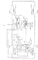
図1〜図6は本発明の実施の第1形態を示し、図1は車両挙動制御装置を搭載した車両の全体構成図、図2は左右駆動力配分制御装置の概略構成図、図3はヨーモーメント補正装置と車両挙動制御装置の機能ブロック図、図4は左右駆動力配分比の特性図、図5は4輪車の等価的な2輪車モデルを示す説明図、図6は各コーナリングパワの説明図である。
Hereinafter, embodiments of the present invention will be described with reference to the drawings.
1 to 6 show a first embodiment of the present invention, FIG. 1 is an overall configuration diagram of a vehicle equipped with a vehicle behavior control device, FIG. 2 is a schematic configuration diagram of a left and right driving force distribution control device, and FIG. 4 is a functional block diagram of the yaw moment correction device and the vehicle behavior control device, FIG. 4 is a characteristic diagram of the left / right driving force distribution ratio, FIG. 5 is an explanatory diagram showing an equivalent two-wheel vehicle model of a four-wheel vehicle, and FIG. It is explanatory drawing of power.
図1において、符号1は自動車等の車両を示す。本第1形態においては、車両1は、FF(Front engin-Front drive)車であり、この車両1のエンジン2による駆動力は、トルクコンバータ3、変速装置4を経て、トランスミッション出力軸5に伝達される。
トランスミッション出力軸5に伝達された駆動力は、リダクションギヤ列6を介して、フロントドライブ軸7に伝達され、前輪終減速装置8に入力される。
In FIG. 1,
The driving force transmitted to the
前輪終減速装置8に入力された駆動力は、前輪左アクスル軸9flを経て左前輪10flに伝達される一方、前輪右アクスル軸9frを経て右前輪10frに伝達される。尚、本実施の第1形態は、FF車であるため、左後輪10rlと右後輪10rrには、エンジン2からの駆動力は伝達されない。
前輪終減速装置8は、左右前輪10fl、10frに伝達する駆動力の配分比を、後述する車両駆動力配分制御手段としての左右駆動力配分制御装置50で設定する駆動力配分比に応じて可変に制御自在な構成となっている。
具体的に説明すると、例えば、図2に示すように、前輪終減速装置8は、差動機構部20と、歯車機構部21と、クラッチ機構部22とを有して主要に構成されている。
The driving force input to the front wheel
The front wheel
Specifically, for example, as shown in FIG. 2, the front wheel
差動機構部20は、例えば、ベベルギヤ式の差動機構部(ディファレンシャル装置)で構成され、この差動機構部20のディファレンシャルケース25には、フロントドライブ軸7のドライブピニオン7aに噛合するファイナルギヤ26が周設されている。
The
また、ディファレンシャルケース25内には、一対のディファレンシャルピニオン27が回動自在に軸支されており、これらに噛合する左右のサイドギヤ28l、28rに、左右のアクスル軸9fl、9frが連結されている。
また、歯車機構部21は、前輪右アクスル軸9frに固設する第1、第2の歯車30、31と、前輪左アクスル軸9flに固設する第3、第4の歯車32、33と、これらにそれぞれ噛合する第5〜第8の歯車34〜37とを有して構成されている。本第1形態において、第2の歯車31は第1の歯車30よりも大径の歯車で構成され、その歯数Z2は、第1の歯車30の歯数Z1よりも大きく設定されている。また、第3の歯車32は、第1の歯車30と同径の歯車(歯数Z3=Z1)で構成され、第4の歯車33は、第2の歯車31と同径の歯車(歯数Z4=Z2)で構成されている。また、第5〜第8の歯車34〜37は、アクスル軸9fl、9frと平行な同一回転軸心上に配列されている。第5の歯車34は、第1の歯車30との噛合によって第1の歯車列を構成するもので、その歯数Z5は、第1の歯車列のギヤ比(Z5/Z1)を例えば「1.0」とするよう設定されている。また、第6の歯車35は、第2の歯車31との噛合によって第2の歯車列を構成するもので、その歯数Z6は、第2の歯車列のギヤ比(Z6/Z2)を例えば「0.9」とするように設定されている。また、第7の歯車36は、第3の歯車32との噛合によって第3の歯車列を構成するもので、その歯数Z7は、第3の歯車列のギヤ比(Z7/Z3)を例えば「1.0」とするように設定されている。また、第8の歯車37は、第4の歯車33との間に第4の歯車列を構成するもので、その歯数Z8は、第4の歯車列のギヤ比(Z8/Z4)を例えば「0.9」とするように設定されている。
クラッチ機構部22は、第5の歯車34と第8の歯車37との間を接離自在に締結する第1の油圧多板クラッチ38と、第6の歯車35と第7の歯車36との間を接離自在に締結する第2の油圧多板クラッチ39とを有して構成されている。各油圧多板クラッチ38、39の油圧室(図示せず)には油圧駆動部51(図1参照)が接続されており、油圧駆動部51から供給される油圧によって、第1の油圧多板クラッチ38が締結すると左アクスル軸9flに駆動力が多く配分され、一方、第2の油圧多板クラッチ39が締結すると右アクスル軸9frに駆動力が多く配分される。ここで、各油圧多板クラッチ38、39を締結させるための油圧値は、左右駆動力配分制御装置50で設定される左右前輪10fl、10frの駆動力配分比に応じて油圧駆動部51で演算される値であり、この油圧値の大小によってトルク配分量が可変される。尚、この種の終減速装置の構成については、例えば、特開平11−263140号公報に詳述されており、本第1形態で説明した構成に限定するものではない。
一方、図1において、符号42は、ハンドル角修正手段としての、例えば、モータ、歯車機構、油圧ユニットを備えてステアリングギヤ比を可変に構成した、周知の(例えば、車速感応型の)車両用操舵装置を示し、この車両用操舵装置42が設定するステアリングギヤ比の値は、ステアリングギヤ比可変制御部43から入力される。また、ステアリングギヤ比可変制御部43が設定するステアリングギヤ比は、後述のヨーモーメント補正装置60からの信号により補正され出力される。
A pair of
The
The
On the other hand, in FIG. 1,
次に、左右駆動力配分制御装置50、及び、ヨーモーメント補正装置60について説明する。
Next, the left / right driving force
左右駆動力配分制御装置50には、横加速度センサ101、タービン回転数センサ102、エンジン回転数センサ103、スロットル開度センサ104、トランスミッション制御装置105が接続され、横加速度(d2y/dt2)、タービン回転数Nt、エンジン回転数Nt、スロットル開度θth、トランスミッションギヤ比rgが、それぞれ入力される。
ヨーモーメント補正装置60には、4輪10fl、10fr、10rl、10rrのアクスルハウジング44fl、44fr、44rl、44rrに埋設した、力検出センサ106fl、106fr、106rl、106rrが接続されている。この力検出センサ106fl、106fr、106rl、106rrは、力検出手段として設けられており、例えば、特開平9−2240号公報に開示されるセンサであり、各輪に作用する前後方向(以下、x方向)、左右方向(以下、y方向)、上下方向(以下、z方向)の各力をアクスルハウジング44fl、44fr、44rl、44rrに生じる変位量に基づき検出するものである。具体的には、前輪の力検出センサ106fl、106frからは、前後、左右、上下方向に作用する力Fflx、Ffly、Fflz、Ffrx、Ffry、Ffrzが、後輪の力検出センサ106rl、106rrからは、前後方向に作用する力Frlx、Frrxが、それぞれヨーモーメント補正装置60に入力される。
また、ヨーモーメント補正装置60には、ハンドル角センサ107、及び、路面摩擦係数推定装置108が接続され、ハンドル角θH、路面μ推定値μが入力される。ここで、路面摩擦係数推定装置108は、路面μ推定値μを、例えば、本出願人が、特開平8−2274号公報で提案した推定方法で演算するものである。この路面μ推定方法は、舵角、車速、実ヨーレートにより車両の横運動の運動方程式に基づき前後輪のコーナリングパワを非線形域に拡張して推定し、高μ路(μ=1.0)での前後輪の等価コーナリングパワに対する推定した前後輪のコーナリングパワの比から路面μを推定する。尚、路面μの推定方法は、もちろん、他の方法、例えば本出願人の特開2000−71968号公報等で開示する方法等で求めても良く、また、各輪に生じたすべり率から各輪毎に求めても良い。
そして、左右駆動力配分制御装置50は、図3に示すように、駆動力演算部50aと、左右駆動力配分設定部50bとから主要に構成されている。
A
Force detection sensors 106fl, 106fr, 106rl, 106rr embedded in axle housings 44fl, 44fr, 44rl, 44rr of four wheels 10fl, 10fr, 10rl, 10rr are connected to the yaw
In addition, the
As shown in FIG. 3, the left / right driving force
駆動力演算部50aは、タービン回転数センサ102、エンジン回転数センサ103、スロットル開度センサ104、トランスミッション制御装置105から、タービン回転数Nt、エンジン回転数Nt、スロットル開度θth、トランスミッションギヤ比rgが、それぞれ入力される。
そして、これらの入力を基に、エンジン駆動力Feを、トランスミッションの特性を考慮して以下(1)式により演算して、左右駆動力配分設定部50bに出力する。
Fe=(Tt・rf)/Rw …(1)
ここで、rfはファイナルギヤ比、Rwはタイヤの有効半径、Ttはミッションギヤ後のトルクであり、エンジントルクをTe、トルクコンバータのトルコン比をtconv、動力伝達効率をηとすると、以下(2)式で求められる。
Tt=Te・rg・tconv・η …(2)
この際、エンジントルクTeは、エンジン回転数Neとスロットル開度θthに基づいて予め設定されたマップから求められ、トルコン比tconvは、トルクコンバータの速度比rv(=Nt/Ne)を基に予め設定されたマップから求められる。
左右駆動力配分設定部50bは、横加速度センサ101から横加速度(d2y/dt2)が、駆動力演算部50aからエンジン駆動力Feが入力される。そして、例えば図4に示すように、予め設定しておいたマップを参照して、横加速度(d2y/dt2)に応じた左右の駆動力配分比を求め、この駆動力配分により、エンジン駆動力Feを配分するように油圧駆動部51に信号を出力する。
The driving
Based on these inputs, the engine driving force Fe is calculated by the following equation (1) in consideration of the transmission characteristics, and is output to the left / right driving force
Fe = (Tt · rf) / Rw (1)
Here, rf is the final gear ratio, Rw is the effective radius of the tire, Tt is the torque after the transmission gear, the engine torque is Te, the torque converter torque converter ratio is tconv, and the power transmission efficiency is η. ).
Tt = Te · rg · tconv · η (2)
At this time, the engine torque Te is obtained from a map set in advance based on the engine speed Ne and the throttle opening degree θth, and the torque converter ratio tconv is determined in advance based on the speed ratio rv (= Nt / Ne) of the torque converter. It is obtained from the set map.
The lateral driving force
一方、ヨーモーメント補正装置60は、舵角演算部60a、発生ヨーモーメント演算部60b、修正舵角演算部60c、ステアリングギヤ比演算部60dから主要に構成されている。
On the other hand, the yaw
ここで、まず、ヨーモーメント補正装置60の説明を行うため、初めに必要な方程式を、図5を基に説明する。
Here, first, an equation necessary for describing the yaw
車両横方向の並進運動に関する運動方程式は、前後輪のコーナリングフォース(1輪)をFfy,Fry、車体質量をmとして、
m・(d2y/dt2)=2・Ffy+2・Fry …(3)
で与えられる。
The equation of motion related to the translational motion in the lateral direction of the vehicle is:
m · (d 2 y / dt 2 ) = 2 ·
Given in.
一方、重心点まわりの回転運動に関する運動方程式は、重心から前後輪軸までの距離をLf,Lr、車体の慣性モーメントをIz、ヨー角加速度を(d2ψ/dt2)として、
Iz・(d2ψ/dt2)=2・Ff・Lf−2・Fr・Lr …(4)
で示される。
On the other hand, the equation of motion related to the rotational motion around the center of gravity is, the distance from the center of gravity to the front and rear wheel axis Lf, Lr, of the vehicle body inertial moment Iz, the yaw angular acceleration as (d 2 ψ / dt 2) ,
Iz · (d 2 ψ / dt 2 ) = 2 · Ff · Lf−2 · Fr · Lr (4)
Indicated by
また、車体すべり角をβ、車体すべり角速度を(dβ/dt)、ヨー角速度(ヨーレート)を(dψ/dt)、車速をVとすると、横加速度(d2y/dt2)は、
(d2y/dt2)=V・((dβ/dt)+(dψ/dt)) …(5)
で表される。
Further, when the vehicle slip angle is β, the vehicle slip angular velocity is (dβ / dt), the yaw angular velocity (yaw rate) is (dψ / dt), and the vehicle speed is V, the lateral acceleration (d 2 y / dt 2 ) is
(D 2 y / dt 2 ) = V · ((dβ / dt) + (dψ / dt)) (5)
It is represented by
以上の(3)式〜(5)式で表現される車両運動モデルについて、左右駆動力配分によって生じるヨーモーメントMを前輪修正舵角Δδfによって打ち消すとすると、以下の状態方程式を得る。
(dx(t)/dt)=A・x(t)+B・u(t)+n(t) …(6)
x(t)=[β (dψ/dt)]T
u(t)=[(δf+Δδf) 0]T
n(t)=[0 (M/Iz)]T

a12=1+2・(Lf・Kfa−Lr・Kra)/(M・V2)
a21=2・(Lf・Kfa−Lr・Kra)/(Iz・V)
a22=2・(Lf2・Kfa−Lr2・Kra)/(Iz・V)
b11=2・Kfa/(M・V)
b21=2・Lf・Kfa/Iz
b12=b22=0
ここで、図6に示すように、例えば、前輪においては、前輪すべり角βfと前輪のコーナリングフォースFfyの関係で、前輪すべり角βf1の時点において、実際に生じているコーナリングパワ(所謂、実コーナリングパワ)をKfaとした場合、以下の(7)式により近似して得られる。
Kfa≒Kf−(Kf・|Ffly|)/(4・(μfl2・Fflz2−Fflx2)1/2)
−(Kf・|Ffry|)/(4・(μfr2・Ffrz2−Ffrx2)1/2)…(7)
また、後輪コーナリングパワKraは以下の(8)式により近似して得られる。
Kra≒Kr−(Kr・|Frly|)/(4・(μrl2・Frlz2−Frlx2)1/2)
−(Kr・|Frry|)/(4・(μrr2・Frrz2−Frrx2)1/2)…(8)
ここで、Kf、Krを前後輪の等価コーナリングパワとする。
Assuming that the yaw moment M generated by the left / right driving force distribution is canceled by the front wheel correction steering angle Δδf in the vehicle motion model expressed by the above equations (3) to (5), the following equation of state is obtained.
(Dx (t) / dt) = A · x (t) + B · u (t) + n (t) (6)
x (t) = [β (dψ / dt)] T
u (t) = [(δf + Δδf) 0] T
n (t) = [0 (M / Iz)] T
a12 = 1 + 2 · (Lf · Kfa−Lr · Kra) / (M · V 2 )
a21 = 2 · (Lf · Kfa−Lr · Kra) / (Iz · V)
a22 = 2 · (Lf 2 · Kfa−Lr 2 · Kra) / (Iz · V)
b11 = 2 · Kfa / (MV)
b21 = 2 · Lf · Kfa / Iz
b12 = b22 = 0
Here, as shown in FIG. 6, for example, in the front wheel, the cornering power actually generated at the time of the front wheel slip angle βf1 (so-called actual cornering) due to the relationship between the front wheel slip angle βf and the front wheel cornering force Ffy. When (power) is set to Kfa, it can be approximated by the following equation (7).
Kfa≈Kf− (Kf · | Ffly |) / (4 · (μfl 2 · Fflz 2 −Fflx 2 ) 1/2 )
− (Kf · | Ffry |) / (4 · (μfr 2 · Ffrz 2 −Ffrx 2 ) 1/2 ) (7)
Further, the rear wheel cornering power Kra is obtained by approximation by the following equation (8).
Kra≈Kr− (Kr · | Frly |) / (4 · (μrl 2 · Frlz 2 −Frlx 2 ) 1/2 )
− (Kr · | Frry |) / (4 · (μrr 2 · Frrz 2 −Frrx 2 ) 1/2 ) (8)
Here, Kf and Kr are equivalent cornering powers of the front and rear wheels.
尚、(7)式、及び、(8)式においては、各輪毎に路面μ推定値が代入できるように、路面μ推定値μfl、μfr、μrl、μrrを判別しているが、本第1形態では、全て同一の路面μ推定値となるため、μfl=μfr=μrl=μrr=μとなる。
そして、以上の式の基で、まず、舵角演算部60aには、ハンドル角センサ107からハンドル角θHが入力され、ステアリングギヤ比演算部60dから現在のステアリングギヤ比srが入力される。そして、これらを基に前輪舵角δfを以下の(9)式により演算し、ステアリングギヤ比演算部60dに出力する。
δf=θH/sr …(9)
In the equations (7) and (8), the road surface μ estimated values μfl, μfr, μrl, and μrr are determined so that the road surface μ estimated value can be substituted for each wheel. In one embodiment, since all the road surface μ estimation values are the same, μfl = μfr = μrl = μrr = μ.
Based on the above formula, first, the steering
δf = θH / sr (9)
発生ヨーモーメント演算部60bには、各力検出センサ106fl、106fr、106rl、106rrから、前後方向に作用する力Fflx、Ffrx、Frlx、Frrxが入力され、以下の(10)式により、左右駆動力配分によって生じるヨーモーメントMを演算し、修正舵角演算部60cに出力する。尚、df、drは、前後のトレッド幅である。すなわち、発生ヨーモーメント演算部60bは、ヨーモーメント演算手段として設けられている。
M=(Ffrx−Fflx)・df/2+(Frrx−Frlx)・dr/2 …(10)
Forces Fflx, Ffrx, Frlx, Frrx acting in the front-rear direction are input from the force detection sensors 106fl, 106fr, 106rl, 106rr to the generated
M = (Ffrx−Fflx) · df / 2 + (Frrx−Frlx) · dr / 2 (10)
修正舵角演算部60cは、前輪の力検出センサ106fl、106frから前後、左右、上下方向に作用する力Fflx、Ffly、Fflz、Ffrx、Ffry、Ffrzが入力され、路面摩擦係数推定装置108からは路面μ推定値μが入力され、発生ヨーモーメント演算部60bからは、ヨーモーメントMが入力される。
そして、以下の(11)式に基づき前輪修正舵角Δδfを演算し、ステアリングギヤ比演算部60dに出力する。
Δδf=−M/(Iz・b21) …(11)
ここで、(11)式中のb21は、状態方程式(6)式のものであり、b21中に含まれる。
すなわち、修正舵角演算部60cは、コーナリングパワ演算手段、及び、補正手段としての機能を有して構成されている。
The corrected rudder
Then, the front wheel correction steering angle Δδf is calculated based on the following equation (11), and is output to the steering gear
Δδf = −M / (Iz · b21) (11)
Here, b21 in the equation (11) is in the equation (6) and is included in b21.
That is, the corrected rudder
ステアリングギヤ比演算部60dは、舵角演算部60aから前輪舵角δfが入力され、修正舵角演算部60cから前輪修正舵角Δδfが入力され、以下の(12)式により、現在設定されているステアリングギヤ比srを基に、新たなステアリングギヤ比srnewを演算し、この新たなステアリングギヤ比の修正量srnewをステアリングギヤ比可変制御部に出力する。
srnew=(δf/(δf+Δδf))・sr …(12)
従って、ステアリングギヤ比演算部60dも、補正手段としての機能を有している。
The steering gear
srnew = (δf / (δf + Δδf)) · sr (12)
Therefore, the steering gear
また、(7)式については、タイヤの横力Ffly、Ffry、Frryの値を用いずに、前後輪のタイヤ滑り角βf、βrを使った以下の(7’)式を用いてもよい。
Kfa≒Kf−(Kf2・|βf|)/(4・(μfl2・Fflz2−Fflx2)1/2)
−(Kf2・|βf|)/(4・(μfr2・Ffrz2−Ffrx2)1/2)…(7’)
As for the equation (7), the following equation (7 ′) using the tire slip angles βf, βr of the front and rear wheels may be used without using the values of the lateral forces Ffly, Ffry, Frry of the tire.
Kfa≈Kf− (Kf 2 · | βf |) / (4 · (μfl 2 · Fflz 2 −Fflx 2 ) 1/2 )
− (Kf 2 · | βf |) / (4 · (μfr 2 · Ffrz 2 −Ffrx 2 ) 1/2 ) (7 ′)
このように、本実施の第1形態によれば、各力検出センサ106fl、106fr、106rl、106rrから直接検出される、左右の制駆動力差によって生じるヨーモーメントMに対して、舵角を制御することで、車両全体のヨーモーメントを一定に保つようになっているので、ドライバが所望する以外のヨーモーメントをレスポンス良く打ち消すことができ、安定性を向上させることが可能になっている。そして、この制御を付加することにより、左右の制駆動力配分制御によるタイヤグリップの効率的な使用が可能となり、タイヤのすべり角の減少、ドライバの違和感の低減が両立でき、その結果として、速さと安定性の両立を実現することができる。また、使用するセンサも、力検出センサ106fl、106fr、106rl、106rrのみでよいので、従来のようなパラメータ推定による、センサ誤差が生じることもなく、また、コストの低減を図ることも可能となる。
次に、図7及び図8は本発明の実施の第2形態を示し、図7は車両挙動制御装置を搭載した車両の全体構成図、図8はヨーモーメント補正装置と車両挙動制御装置の機能ブロック図である。尚、本実施の第2形態は、車両駆動力配分制御手段としての左右駆動力配分制御装置のみが、前記第1形態とは異なり、他の構成、作用効果は前記第1形態と同様であるので、同じ符号を記し、説明は省略する。
Thus, according to the first embodiment, the steering angle is controlled with respect to the yaw moment M generated by the left / right braking / driving force difference, which is directly detected from the force detection sensors 106fl, 106fr, 106rl, and 106rr. By doing so, the yaw moment of the entire vehicle is kept constant, so that yaw moments other than those desired by the driver can be canceled with good response, and stability can be improved. By adding this control, the right and left braking / driving force distribution control enables efficient use of the tire grip, which can both reduce the tire slip angle and reduce the driver's uncomfortable feeling. And stability can be realized. In addition, since only the force detection sensors 106fl, 106fr, 106rl, and 106rr are used, no sensor error occurs due to parameter estimation as in the prior art, and the cost can be reduced. .
Next, FIGS. 7 and 8 show a second embodiment of the present invention, FIG. 7 is an overall configuration diagram of a vehicle equipped with a vehicle behavior control device, and FIG. 8 is a function of the yaw moment correction device and the vehicle behavior control device. It is a block diagram. In the second embodiment, only the left and right driving force distribution control device as the vehicle driving force distribution control means is different from the first embodiment, and the other configurations and operational effects are the same as those of the first embodiment. Therefore, the same reference numerals are given and the description is omitted.
すなわち、図7及び図8において、符号70は左右駆動力配分制御装置を示し、この左右駆動力配分制御装置70には、タービン回転数センサ102、エンジン回転数センサ103、スロットル開度センサ104、トランスミッション制御装置105が接続され、横加速度(d2y/dt2)、タービン回転数Nt、エンジン回転数Nt、スロットル開度θth、トランスミッションギヤ比rgが、それぞれ入力される。
また、左右駆動力配分制御装置70には、前輪の力検出センサ106fl、106frが接続され、上下方向に作用する力Fflz、Ffrzが入力される。
そして、左右駆動力配分制御装置70は、図8に示すように、駆動力演算部70aと、左右駆動力配分設定部70bとから主要に構成されている。
7 and 8,
The left and right driving force
As shown in FIG. 8, the left / right driving force
駆動力演算部70aは、前記第1形態における駆動力演算部50aと同様に、タービン回転数センサ102、エンジン回転数センサ103、スロットル開度センサ104、トランスミッション制御装置105から、タービン回転数Nt、エンジン回転数Nt、スロットル開度θth、トランスミッションギヤ比rgが、それぞれ入力される。そして、これらの入力を基に、エンジン駆動力Feを、トランスミッションの特性を考慮して前述の(1)式により演算し、左右駆動力配分設定部70bに出力する。
左右駆動力配分設定部70bは、前輪の力検出センサ106fl、106frから上下方向に作用する力Fflz、Ffrzが入力され、駆動力演算部70aからエンジン駆動力Feが入力される。そして、以下の(13)式により左右の駆動力配分比を設定し、この駆動力配分により、エンジン駆動力Feを配分するように油圧駆動部51に信号を出力する。
(左前輪の駆動力配分):(右前輪の駆動力配分)
=(Fflz/(Fflz+Ffrz)):(Ffrz/(Fflz+Ffrz)) …(13)
Similarly to the driving
The left and right driving force
(Left front wheel drive force distribution): (Right front wheel drive force distribution)
= (Fflz / (Fflz + Ffrz)): (Ffrz / (Fflz + Ffrz)) (13)
このように、本実施の第2形態のように、左右駆動力配分制御の異なるものであっても、前記第1形態と同様の効果を得ることができる。 Thus, even if the left and right driving force distribution control is different as in the second embodiment, the same effect as in the first embodiment can be obtained.
次に、図9及び図10は本発明の実施の第3形態を示し、図9は車両挙動制御装置を搭載した車両の全体構成図、図10はヨーモーメント補正装置と車両挙動制御装置の機能ブロック図である。尚、本実施の第3形態は、車両駆動力配分制御手段としての左右駆動力配分制御装置のみが、前記第1、第2形態とは異なり、他の構成、作用効果は前記第1、第2形態と同様であるので、同じ符号を記し、説明は省略する。 Next, FIGS. 9 and 10 show a third embodiment of the present invention, FIG. 9 is an overall configuration diagram of a vehicle equipped with a vehicle behavior control device, and FIG. 10 shows the functions of the yaw moment correction device and the vehicle behavior control device. It is a block diagram. In the third embodiment, only the left and right driving force distribution control device as the vehicle driving force distribution control means is different from the first and second embodiments, and the other configurations and operational effects are the first and second. Since it is the same as that of 2 forms, the same code | symbol is described and description is abbreviate | omitted.
すなわち、図9及び図10において、符号80は左右駆動力配分制御装置を示し、この左右駆動力配分制御装置80には、タービン回転数センサ102、エンジン回転数センサ103、スロットル開度センサ104、トランスミッション制御装置105、路面摩擦係数推定装置108が接続され、横加速度(d2y/dt2)、タービン回転数Nt、エンジン回転数Nt、スロットル開度θth、トランスミッションギヤ比rg、路面μ推定値μが、それぞれ入力される。
また、左右駆動力配分制御装置80には、前輪の力検出センサ106fl、106frが接続され、左右、上下方向に作用する力Ffly、Fflz、Ffry、Ffrzが入力される。
そして、左右駆動力配分制御装置80は、図10に示すように、駆動力演算部80aと、左右駆動力配分設定部80bとから主要に構成されている。
That is, in FIGS. 9 and 10,
The left and right driving force
As shown in FIG. 10, the left / right driving force
駆動力演算部80aは、前記第1形態における駆動力演算部50aと同様に、タービン回転数センサ102、エンジン回転数センサ103、スロットル開度センサ104、トランスミッション制御装置105から、タービン回転数Nt、エンジン回転数Nt、スロットル開度θth、トランスミッションギヤ比rgが、それぞれ入力される。そして、これらの入力を基に、エンジン駆動力Feを、トランスミッションの特性を考慮して前述の(1)式により演算し、左右駆動力配分設定部80bに出力する。
左右駆動力配分設定部80bは、路面摩擦係数推定装置108から路面μ推定値μが入力され、前輪の力検出センサ106fl、106frから左右、上下方向に作用する力Ffly、Fflz、Ffry、Ffrzが入力され、駆動力演算部80aからエンジン駆動力Feが入力される。そして、以下の(14)式により、左右輪の摩擦円利用率が等しくなるように、左右の駆動力配分比aを設定し、この駆動力配分により、エンジン駆動力Feを配分するように油圧駆動部51に信号を出力する。
(a2・Fe2+Ffly2)1/2/(μfl・Fflz)
=((1−a)2・Fe2+Ffry2)1/2/(μfr・Ffrz) …(14)
尚、(14)式においては、各輪毎に路面μ推定値が代入できるように、路面μ推定値μfl、μfrを判別しているが、本第3形態では、全て同一の路面μ推定値となるため、μfl=μfr=μとなる。
このように、本実施の第3形態のように、左右駆動力配分制御の異なるものであっても、前記第1形態と同様の効果を得ることができる。
Similarly to the driving
The left and right driving force distribution setting unit 80b receives the road surface μ estimated value μ from the road surface friction
(A 2 · Fe 2 + Ffly 2 ) 1/2 / (μfl · Fflz)
= ((1-a) 2 · Fe 2 + Ffry 2 ) 1/2 / (μfr · Ffrz) (14)
In the equation (14), the road surface μ estimated values μfl and μfr are discriminated so that the road surface μ estimated value can be substituted for each wheel. However, in the third embodiment, the same road surface μ estimated value is used. Therefore, μfl = μfr = μ.
Thus, even if the left and right driving force distribution control is different as in the third embodiment, the same effect as in the first embodiment can be obtained.
次に、図11及び図12は本発明の実施の第4形態を示し、図11は車両挙動制御装置を搭載した車両の全体構成図、図12はヨーモーメント補正装置と車両挙動制御装置の機能ブロック図である。尚、本実施の第4形態は、ヨーモーメント補正装置のみが、前記第1形態とは異なり、他の構成、作用効果は前記第1形態と同様であるので、同じ符号を記し、説明は省略する。 Next, FIGS. 11 and 12 show a fourth embodiment of the present invention, FIG. 11 is an overall configuration diagram of a vehicle equipped with a vehicle behavior control device, and FIG. 12 is a function of the yaw moment correction device and the vehicle behavior control device. It is a block diagram. In the fourth embodiment, only the yaw moment correction device is different from the first embodiment, and the other configurations and functions and effects are the same as those in the first embodiment. To do.
すなわち、図9及び図10において、符号90はヨーモーメント補正装置を示し、このヨーモーメント補正装置90には、力検出センサ106fl、106fr、106rl、106rrが接続され、各車輪毎の前後、左右、上下方向に作用する力Fflx、Ffly、Fflz、Ffrx、Ffry、Ffrz、Frlx、Frly、Frlz、Frrx、Frry、Frrzが入力される。
また、ヨーモーメント補正装置90には、ハンドル角センサ107、路面摩擦係数推定装置108、車速センサ109、及び、ヨーレートセンサ110が接続され、ハンドル角θH、路面μ推定値μ、車速V、実ヨーレート(dψ/dt)sが入力される。
そして、図12に示すように、ヨーモーメント補正装置90は、舵角演算部60a、発生ヨーモーメント演算部60b、修正舵角演算部60c、目標ヨーレート演算部90a、ヨーレート偏差演算部90b、ヨーレートによる舵角修正量演算部90c、ステアリングギヤ比演算部90dから主要に構成されている。
That is, in FIGS. 9 and 10,
Further, the
As shown in FIG. 12, the yaw
目標ヨーレート演算部90aは、力検出センサ106fl、106fr、106rl、106rrから各車輪毎の前後、左右、上下方向に作用する力Fflx、Ffly、Fflz、Ffrx、Ffry、Ffrz、Frlx、Frly、Frlz、Frrx、Frry、Frrzが入力され、ハンドル角センサ107からハンドル角θHが入力され、路面摩擦係数推定装置108から路面μ推定値μが入力され、車速センサ109から車速Vが入力される。
そして、以下の(15)式により、目標ヨーレート(dψ/dt)tを演算し、ヨーレート偏差演算部90bに出力する。
(dψ/dt)t=G(0)・(1/(1+Tr・s))・δf …(15)
ここで、G(0)はヨーレート定常ゲイン、Trは時定数、sはラプラス演算子であり、例えば、時定数Trは以下の(16)式から、ヨーレート定常ゲインG(0)は、以下の(17)式から求められる。
Tr=(m・Lf・V)/(2・L・kra) …(16)
ここで、Lはホイールベース、kraは前述の(8)式で得られる後輪コーナリングパワである。
G(0)=(1/(1+sf・V2))・(V/L) …(17)
ここで、sfは車両諸元で決まるスタビリティファクタであり、例えば、以下(18)式により演算される。
sf=−m/(2・L2)・(Lf・kfa−Lr・kra)
/(kfa・kra) …(18)
ここで、kfaは前述の(7)式で得られる前輪コーナリングパワである。
ヨーレート偏差演算部90bは、ヨーレートセンサ110から実ヨーレート(dψ/dt)sが入力され、目標ヨーレート演算部90aから目標ヨーレート(dψ/dt)tが入力され、以下(19)式によりヨーレート偏差Δ(dψ/dt)を演算して、ヨーレートによる舵角修正量演算部90cに出力する。
Δ(dψ/dt)=(dψ/dt)s−(dψ/dt)t …(19)
すなわち、目標ヨーレート演算部90a及びヨーレート偏差演算部90bで、ヨーレート偏差演算手段が構成されている。
The target yaw rate calculation unit 90a is configured to apply force Fflx, Ffly, Fflz, Ffrx, Ffry, Ffrz, Frlx, Flyx, Frlx, Frlx, Ffrx, Ffrx, Ffry, Ffrz, Frlx, Frrx, Frry, and Frrz are input, the steering wheel angle θH is input from the steering
Then, the target yaw rate (dψ / dt) t is calculated by the following equation (15), and is output to the yaw rate deviation calculating unit 90b.
(Dψ / dt) t = G (0) · (1 / (1 + Tr · s)) · δf (15)
Here, G (0) is a yaw rate steady gain, Tr is a time constant, and s is a Laplace operator. For example, the time constant Tr is obtained from the following equation (16), and the yaw rate steady gain G (0) is It can be obtained from equation (17).
Tr = (m · Lf · V) / (2 · L · kra) (16)
Here, L is a wheel base, and kra is a rear wheel cornering power obtained by the above-described equation (8).
G (0) = (1 / (1 + sf · V 2 )) · (V / L) (17)
Here, sf is a stability factor determined by vehicle specifications, and is calculated by the following equation (18), for example.
sf = −m / (2 · L 2 ) · (Lf · kfa−Lr · kra)
/ (Kfa ・ kra) (18)
Here, kfa is a front wheel cornering power obtained by the above-described equation (7).
The yaw rate deviation calculating unit 90b receives the actual yaw rate (dψ / dt) s from the
Δ (dψ / dt) = (dψ / dt) s− (dψ / dt) t (19)
That is, the target yaw rate calculation unit 90a and the yaw rate deviation calculation unit 90b constitute a yaw rate deviation calculation means.
ヨーレートによる舵角修正量演算部90cは、ヨーレート偏差演算部90bからヨーレート偏差Δ(dψ/dt)が入力され、例えば、以下(20)式によりヨーレートによる舵角修正量Δδfyoを演算して、ステアリングギヤ比演算部90dに出力する。
Δδfyo=kfyo・Δ(dψ/dt) …(20)
ここで、kfyoは予め実験・計算等により設定しておいたゲインである。
ステアリングギヤ比演算部90dは、舵角演算部60aから前輪舵角δfが入力され、修正舵角演算部60cから前輪修正舵角Δδfが入力され、ヨーレートによる舵角修正量演算部90cからヨーレートによる舵角修正量Δδfyoが入力され、以下の(21)式により、現在設定されているステアリングギヤ比srを基に、新たなステアリングギヤ比srnewを演算し、この新たなステアリングギヤ比の修正量srnewをステアリングギヤ比可変制御部に出力する。
srnew=(δf/(δf+Δδf+Δδfyo))・sr …(21)
The steering angle correction
Δδfyo = kfyo · Δ (dψ / dt) (20)
Here, kfyo is a gain set in advance through experiments and calculations.
The steering gear
srnew = (δf / (δf + Δδf + Δδfyo)) · sr (21)
従って、本実施の第4形態においては、修正量演算部60c、ヨーレートによる舵角修正量演算部90c、及び、ステアリングギヤ比演算部60dにより、補正手段が構成されている。
Therefore, in the fourth embodiment, the correction means is configured by the correction
このように、本実施の第4形態によれば、目標ヨーレート(dψ/dt)tをフィードバックすることによっても、ヨーモーメントの修正が行われるため、第1形態の効果に加え、より制御が滑らかになり、精度良く行えるこという効果をえることが可能となる。
尚、本実施の第4形態では、左右駆動力配分制御装置は、第1形態によるもので説明しているが、第2、第3形態によるものであっても適用でき、更に、他の周知の左右駆動力配分制御装置においても適用できることは云うまでもない。
As described above, according to the fourth embodiment, the yaw moment is also corrected by feeding back the target yaw rate (dψ / dt) t. Therefore, in addition to the effects of the first embodiment, the control is smoother. Thus, it is possible to obtain the effect of being able to perform with high accuracy.
In the fourth embodiment, the left and right driving force distribution control device is described according to the first embodiment. However, the left and right driving force distribution control device can be applied to the second and third embodiments. It goes without saying that the present invention can also be applied to the left and right driving force distribution control apparatus.
また、本実施の各形態では、FF車を例に、駆動力を左右に配分制御する例で説明したが、FF車に限るものではなく、FR(Front engine-Rear drive)車、RR(Rear engine-Rear drive)車、4輪駆動車においても、駆動力を左右に配分する制御を有する車両に適用できる。また、4輪駆動車においては、駆動力を前後に配分する制御に、本発明を組み合わせて協調制御させることもできる。更には、4輪にモータを備え、各モータを制御することで駆動力を得る4輪独立モータ車両においても、左右輪のモータ駆動力、更には4輪のモータ駆動力を本発明により算出される駆動力配分に制御することで適用することができる。この場合においては、各輪に対する駆動力を算出及び制御するユニットが車両駆動力配分制御手段に該当する。
また、本実施の各形態においては、左右に配分する駆動力を、タービン回転数Nt、エンジン回転数Nt、スロットル開度θth、トランスミッションギヤ比rgから演算して求めているが、エンジン駆動力Feは、燃料噴射パルス等、周知の信号から得るようにしても良い。
更に、本実施の各形態においては、エンジン駆動力Feを左右に駆動力配分するようにしているが、制動の際に、制動力も積極的に左右に駆動力配分するものであっても良い。
In each of the embodiments, the FF vehicle is taken as an example and the driving force is distributed and controlled to the left and right. However, the present invention is not limited to the FF vehicle, and is not limited to the FF vehicle, but is an FR (Front engine-Rear drive) vehicle, RR (Rear It can also be applied to a vehicle having control for distributing the driving force to the left and right in an engine-rear drive vehicle and a four-wheel drive vehicle. In a four-wheel drive vehicle, the present invention can be combined with the control for distributing the driving force back and forth to perform cooperative control. Further, even in a four-wheel independent motor vehicle that includes a motor on four wheels and obtains a driving force by controlling each motor, the motor driving force for the left and right wheels and the motor driving force for the four wheels are calculated by the present invention. It can be applied by controlling the driving force distribution. In this case, the unit for calculating and controlling the driving force for each wheel corresponds to the vehicle driving force distribution control means.
In each of the embodiments, the driving force distributed to the left and right is obtained by calculating from the turbine rotational speed Nt, the engine rotational speed Nt, the throttle opening θth, and the transmission gear ratio rg. May be obtained from a known signal such as a fuel injection pulse.
Further, in each of the embodiments, the engine driving force Fe is distributed to the left and right. However, the braking force may also be positively distributed to the left and right during braking. .
また、本実施の各形態では、それぞれのヨーモーメント補正装置は、新たなステアリングギヤ比をステアリングギヤ比可変制御部43に出力して、ヨーモーメントの減少を図る例で説明したが、バイワイヤ(by-wire)方式の操舵制御装置を搭載して、直接、新たな操舵角を入力し、ヨーモーメントの減少を図るようにしても良い。
In each embodiment, each yaw moment correction device has been described with an example in which a new steering gear ratio is output to the steering gear ratio
1 車両
2 エンジン
8 前輪終減速装置
10fl、10fr、10rl、10rr 車輪
42 車両用操舵装置
43 ステアリングギヤ比可変制御部
50 左右駆動力配分制御装置(車両駆動力配分制御手段)
50a 駆動力演算部
50b 左右駆動力配分設定部
51 油圧駆動部
60 ヨーモーメント補正装置
60a 舵角演算部
60b 発生ヨーモーメント演算部(ヨーモーメント演算手段)
60c 修正舵角演算部(コーナリングパワ演算手段、補正手段)
60d ステアリングギヤ比演算部(補正手段)
106fl、106fr、106rl、106rr 力検出センサ(力検出手段)
代理人 弁理士 伊 藤 進
1
42 Steering device for
50a Driving
60c Modified rudder angle calculation unit (cornering power calculation means, correction means)
60d Steering gear ratio calculation unit (correction means)
106fl, 106fr, 106rl, 106rr Force detection sensor (force detection means)
Agent Patent Attorney Susumu Ito
Claims (1)
車両の左側車輪と右側車輪との間の駆動力配分を制御する車両駆動力配分制御手段と、
上記力検出手段で検出した各力に基づいて各車輪に伝達する駆動力により発生する車体のヨーモーメントを演算するヨーモーメント演算手段と、
上記力検出手段で検出した各力に基づいて各車輪のコーナリングパワを演算するコーナリングパワ演算手段と、
車両の慣性モーメントと上記コーナリングパワに基づいて上記車両駆動力配分制御手段の作動の際の駆動力により発生する車体のヨーモーメントを減少補正するヨーモーメントとして演算し、該減少補正するヨーモーメントをステアリングギヤ比に換算する補正手段と、
上記換算されたステアリングギヤ比に基づいてステアリングギヤ比を可変するステアリングギヤ比を可変に構成したハンドル角修正手段と、
を備えたことを特徴とする車両の挙動制御装置。 Force detecting means for detecting the force acting on each wheel of the vehicle;
Vehicle driving force distribution control means for controlling the driving force distribution between the left and right wheels of the vehicle;
Yaw moment calculating means for calculating the yaw moment of the vehicle body generated by the driving force transmitted to each wheel based on each force detected by the force detecting means;
Cornering power calculating means for calculating the cornering power of each wheel based on each force detected by the force detecting means;
Based on the inertia moment of the vehicle and the cornering power, the yaw moment of the vehicle body generated by the driving force when the vehicle driving force distribution control means is actuated is calculated as a yaw moment for reducing correction, and the yaw moment for correcting the reduction is steered Correction means for converting to a gear ratio;
A steering wheel angle correcting means that variably configures a steering gear ratio that varies the steering gear ratio based on the converted steering gear ratio;
A vehicle behavior control apparatus comprising:
Priority Applications (2)
| Application Number | Priority Date | Filing Date | Title |
|---|---|---|---|
| JP2004228429A JP4638185B2 (en) | 2004-08-04 | 2004-08-04 | Vehicle behavior control device |
| US11/196,769 US20060041364A1 (en) | 2004-08-04 | 2005-08-03 | Vehicle behavior control device |
Applications Claiming Priority (1)
| Application Number | Priority Date | Filing Date | Title |
|---|---|---|---|
| JP2004228429A JP4638185B2 (en) | 2004-08-04 | 2004-08-04 | Vehicle behavior control device |
Publications (2)
| Publication Number | Publication Date |
|---|---|
| JP2006044463A JP2006044463A (en) | 2006-02-16 |
| JP4638185B2 true JP4638185B2 (en) | 2011-02-23 |
Family
ID=35910651
Family Applications (1)
| Application Number | Title | Priority Date | Filing Date |
|---|---|---|---|
| JP2004228429A Expired - Fee Related JP4638185B2 (en) | 2004-08-04 | 2004-08-04 | Vehicle behavior control device |
Country Status (2)
| Country | Link |
|---|---|
| US (1) | US20060041364A1 (en) |
| JP (1) | JP4638185B2 (en) |
Families Citing this family (14)
| Publication number | Priority date | Publication date | Assignee | Title |
|---|---|---|---|---|
| JP4929944B2 (en) * | 2006-09-20 | 2012-05-09 | 日産自動車株式会社 | Vehicle driving force distribution control device |
| JP2008207671A (en) * | 2007-02-26 | 2008-09-11 | Fuji Heavy Ind Ltd | Vehicle control device |
| CN102421655A (en) * | 2009-05-13 | 2012-04-18 | 丰田自动车株式会社 | Specification information estimation device and vehicle |
| JP5143103B2 (en) | 2009-09-30 | 2013-02-13 | 日立オートモティブシステムズ株式会社 | Vehicle motion control device |
| JP5588388B2 (en) * | 2011-03-25 | 2014-09-10 | 株式会社豊田中央研究所 | Steering device |
| JP6604894B2 (en) | 2016-04-12 | 2019-11-13 | 日立オートモティブシステムズ株式会社 | Vehicle control apparatus and method |
| US10124827B2 (en) | 2016-08-31 | 2018-11-13 | Deere & Company | Methods and apparatuses for determining estimates of a vehicle's wheel angle and the vehicle's steering ratio |
| JP6663333B2 (en) * | 2016-09-23 | 2020-03-11 | 株式会社Subaru | Vehicle control device and vehicle control method |
| CN107817720B (en) * | 2017-10-24 | 2019-10-25 | 深圳市创客工场科技有限公司 | A kind of steering gear control system and method |
| JP7429902B2 (en) * | 2019-08-21 | 2024-02-09 | パナソニックIpマネジメント株式会社 | self-propelled robot |
| CN111086400B (en) * | 2020-01-19 | 2021-06-25 | 北京理工大学 | Method and system for direct force dynamics control of all-wheel independent steering and independent drive unmanned vehicles |
| CN116133933A (en) * | 2020-07-28 | 2023-05-16 | 日立安斯泰莫株式会社 | Vehicle control device, vehicle control method, and vehicle control system |
| CN111845710B (en) * | 2020-08-03 | 2023-10-03 | 北京理工大学 | Whole vehicle dynamic performance control method and system based on road surface adhesion coefficient identification |
| CN114802442B (en) * | 2022-05-06 | 2023-09-05 | 小米汽车科技有限公司 | Vehicle transverse control method and device, storage medium and vehicle |
Citations (5)
| Publication number | Priority date | Publication date | Assignee | Title |
|---|---|---|---|---|
| JPH06219305A (en) * | 1993-01-21 | 1994-08-09 | Toyota Motor Corp | Vehicle control device |
| JP2000043747A (en) * | 1998-07-30 | 2000-02-15 | Koyo Seiko Co Ltd | Steering apparatus for vehicle |
| JP2002316633A (en) * | 2001-04-20 | 2002-10-29 | Fuji Heavy Ind Ltd | Vehicle motion control device |
| JP2004149107A (en) * | 2002-09-04 | 2004-05-27 | Fuji Heavy Ind Ltd | Cornering power control device and cornering power control method |
| JP2004175192A (en) * | 2002-11-26 | 2004-06-24 | Toyota Motor Corp | Vehicle steering control device |
Family Cites Families (41)
| Publication number | Priority date | Publication date | Assignee | Title |
|---|---|---|---|---|
| JP2762711B2 (en) * | 1990-07-02 | 1998-06-04 | 日産自動車株式会社 | Vehicle braking behavior compensator |
| JPH05185801A (en) * | 1992-01-10 | 1993-07-27 | Nissan Motor Co Ltd | Behavior control device of vehicle |
| US5774821A (en) * | 1994-11-25 | 1998-06-30 | Itt Automotive Europe Gmbh | System for driving stability control |
| JP3225790B2 (en) * | 1995-06-09 | 2001-11-05 | トヨタ自動車株式会社 | Vehicle behavior control device |
| JP3553735B2 (en) * | 1996-06-13 | 2004-08-11 | 正人 安部 | Vehicle behavior control method and device |
| DE19623595A1 (en) * | 1996-06-13 | 1997-12-18 | Teves Gmbh Alfred | Method for regulating the driving behavior of a vehicle |
| US5979581A (en) * | 1996-11-07 | 1999-11-09 | The Regents Of The University Of California | Lateral vehicle control apparatus and method for automated highway systems and intelligent cruise control |
| JPH10264798A (en) * | 1997-03-27 | 1998-10-06 | Mazda Motor Corp | Vehicle attitude control device |
| JP3937524B2 (en) * | 1997-09-30 | 2007-06-27 | トヨタ自動車株式会社 | Vehicle braking / driving force control device |
| DE19744725A1 (en) * | 1997-10-10 | 1999-04-15 | Itt Mfg Enterprises Inc | Method to determine variable characteristics, which define motor vehicle behavior |
| JP3850530B2 (en) * | 1997-10-21 | 2006-11-29 | 富士重工業株式会社 | Vehicle motion control device |
| JP3458734B2 (en) * | 1998-04-09 | 2003-10-20 | トヨタ自動車株式会社 | Vehicle motion control device |
| EP0995656A4 (en) * | 1998-05-07 | 2002-10-24 | Unisia Jecs Corp | Device for controlling yawing of vehicle |
| DE69935090T2 (en) * | 1998-06-09 | 2007-11-15 | Fuji Jukogyo K.K. | Torque distribution control system for a four-wheel drive vehicle |
| US6663113B2 (en) * | 1998-10-09 | 2003-12-16 | Robert Bosch Gmbh | System and method for reducing stopping distance and improving traction in motor vehicles |
| US6415215B1 (en) * | 2000-02-23 | 2002-07-02 | Koyo Seiko Co., Ltd. | Vehicle attitude control apparatus |
| EP1147960A1 (en) * | 2000-04-18 | 2001-10-24 | Société de Technologie Michelin | Vehicle stability control method using tyre lateral forces |
| JP2002012160A (en) * | 2000-06-29 | 2002-01-15 | Fuji Heavy Ind Ltd | Road surface friction coefficient estimation device for vehicles |
| DE10039782A1 (en) * | 2000-08-16 | 2002-02-28 | Daimler Chrysler Ag | Method for regulating yaw and lateral dynamics in a road vehicle |
| JP3539722B2 (en) * | 2000-11-16 | 2004-07-07 | 富士重工業株式会社 | Road surface friction coefficient estimation device for vehicles |
| JP3601487B2 (en) * | 2000-11-20 | 2004-12-15 | トヨタ自動車株式会社 | Vehicle braking / driving force control device |
| US6453226B1 (en) * | 2001-01-25 | 2002-09-17 | Delphi Technologies, Inc. | Integrated control of active tire steer and brakes |
| JP3623456B2 (en) * | 2001-02-28 | 2005-02-23 | トヨタ自動車株式会社 | Vehicle travel control device |
| JP4394304B2 (en) * | 2001-04-24 | 2010-01-06 | 富士重工業株式会社 | Vehicle motion control device |
| JP3808744B2 (en) * | 2001-10-11 | 2006-08-16 | 本田技研工業株式会社 | Vehicle motion control device |
| JP3798668B2 (en) * | 2001-10-11 | 2006-07-19 | 本田技研工業株式会社 | Road friction coefficient calculation device |
| US7676307B2 (en) * | 2001-11-05 | 2010-03-09 | Ford Global Technologies | System and method for controlling a safety system of a vehicle in response to conditions sensed by tire sensors related applications |
| DE60318919T2 (en) * | 2002-03-29 | 2009-01-29 | Advics Co., Ltd., Kariya | Vehicle control device with power steering |
| JP2003306092A (en) * | 2002-04-16 | 2003-10-28 | Honda Motor Co Ltd | Method for estimating vehicle state quantity |
| JP3950729B2 (en) * | 2002-04-23 | 2007-08-01 | アイシン精機株式会社 | Vehicle motion control device |
| JP2003341500A (en) * | 2002-05-24 | 2003-12-03 | Aisin Seiki Co Ltd | Anti-skid control device |
| JP3829934B2 (en) * | 2002-06-27 | 2006-10-04 | トヨタ自動車株式会社 | Vehicle turning characteristic estimation device |
| JP3964771B2 (en) * | 2002-10-11 | 2007-08-22 | 株式会社豊田中央研究所 | Road surface state estimation device and vehicle motion control device including the device |
| JP4151389B2 (en) * | 2002-11-26 | 2008-09-17 | トヨタ自動車株式会社 | Vehicle behavior control device |
| JP4291003B2 (en) * | 2003-01-23 | 2009-07-08 | 本田技研工業株式会社 | Steering device |
| JP4165380B2 (en) * | 2003-01-31 | 2008-10-15 | 株式会社豊田中央研究所 | Vehicle control method and vehicle control apparatus |
| US6885931B2 (en) * | 2003-04-24 | 2005-04-26 | Visteon Global Technologies, Inc. | Control algorithm for a yaw stability management system |
| JP4293431B2 (en) * | 2003-06-11 | 2009-07-08 | 富士重工業株式会社 | Vehicle control apparatus and vehicle control method |
| US7137673B2 (en) * | 2003-06-27 | 2006-11-21 | Visteon Global Technologies, Inc. | Vehicle yaw stability system and method |
| US6923510B2 (en) * | 2003-09-17 | 2005-08-02 | Delphi Technologies, Inc. | Control of brake-and steer-by-wire systems during brake failure |
| JP2005112007A (en) * | 2003-10-02 | 2005-04-28 | Toyoda Mach Works Ltd | Vehicular integrated control device |
-
2004
- 2004-08-04 JP JP2004228429A patent/JP4638185B2/en not_active Expired - Fee Related
-
2005
- 2005-08-03 US US11/196,769 patent/US20060041364A1/en not_active Abandoned
Patent Citations (5)
| Publication number | Priority date | Publication date | Assignee | Title |
|---|---|---|---|---|
| JPH06219305A (en) * | 1993-01-21 | 1994-08-09 | Toyota Motor Corp | Vehicle control device |
| JP2000043747A (en) * | 1998-07-30 | 2000-02-15 | Koyo Seiko Co Ltd | Steering apparatus for vehicle |
| JP2002316633A (en) * | 2001-04-20 | 2002-10-29 | Fuji Heavy Ind Ltd | Vehicle motion control device |
| JP2004149107A (en) * | 2002-09-04 | 2004-05-27 | Fuji Heavy Ind Ltd | Cornering power control device and cornering power control method |
| JP2004175192A (en) * | 2002-11-26 | 2004-06-24 | Toyota Motor Corp | Vehicle steering control device |
Also Published As
| Publication number | Publication date |
|---|---|
| US20060041364A1 (en) | 2006-02-23 |
| JP2006044463A (en) | 2006-02-16 |
Similar Documents
| Publication | Publication Date | Title |
|---|---|---|
| JP3046108B2 (en) | Steering force control method for vehicle with differential limiting device | |
| JP4918149B2 (en) | Vehicle motion control device | |
| US7797094B2 (en) | Turning control apparatus for vehicle | |
| US8355844B2 (en) | Vehicle motion control apparatus | |
| US7171296B2 (en) | Integrated control apparatus for vehicle | |
| JP4638185B2 (en) | Vehicle behavior control device | |
| US20050096830A1 (en) | Integrated control apparatus for vehicle | |
| JP3946294B2 (en) | Braking force control device | |
| JPH1159216A (en) | Power distributing control device for four-wheel drive vehicle | |
| JP2009184575A (en) | Vehicle control device | |
| US8239111B2 (en) | Vehicle driving assist system | |
| JP2008207672A (en) | Vehicle braking force control device | |
| JP5351814B2 (en) | Vehicle motion control device | |
| US7628241B2 (en) | Turning control apparatus for vehicle | |
| US8055420B2 (en) | Vehicle control device | |
| JP2009531232A (en) | Understeer / oversteer correction for all-wheel drive vehicles | |
| JP3827837B2 (en) | Vehicle motion control device | |
| JP2008239115A (en) | Vehicle operation controller | |
| US20050205339A1 (en) | Steering control apparatus for a vehicle | |
| JP2000339596A (en) | Vehicle motion control device | |
| US20220306062A1 (en) | Vehicle control system | |
| WO2014103474A1 (en) | Vehicle control device | |
| JP2010208366A (en) | Vehicle drive control system | |
| JP5637695B2 (en) | Control device for driving force distribution device | |
| JP5640581B2 (en) | Control device for differential limiting mechanism |
Legal Events
| Date | Code | Title | Description |
|---|---|---|---|
| A621 | Written request for application examination |
Free format text: JAPANESE INTERMEDIATE CODE: A621 Effective date: 20070402 |
|
| A977 | Report on retrieval |
Free format text: JAPANESE INTERMEDIATE CODE: A971007 Effective date: 20090610 |
|
| A131 | Notification of reasons for refusal |
Free format text: JAPANESE INTERMEDIATE CODE: A131 Effective date: 20091013 |
|
| A521 | Request for written amendment filed |
Free format text: JAPANESE INTERMEDIATE CODE: A523 Effective date: 20091211 |
|
| A131 | Notification of reasons for refusal |
Free format text: JAPANESE INTERMEDIATE CODE: A131 Effective date: 20100302 |
|
| A521 | Request for written amendment filed |
Free format text: JAPANESE INTERMEDIATE CODE: A523 Effective date: 20100423 |
|
| TRDD | Decision of grant or rejection written | ||
| A01 | Written decision to grant a patent or to grant a registration (utility model) |
Free format text: JAPANESE INTERMEDIATE CODE: A01 Effective date: 20101116 |
|
| A01 | Written decision to grant a patent or to grant a registration (utility model) |
Free format text: JAPANESE INTERMEDIATE CODE: A01 |
|
| A61 | First payment of annual fees (during grant procedure) |
Free format text: JAPANESE INTERMEDIATE CODE: A61 Effective date: 20101125 |
|
| FPAY | Renewal fee payment (event date is renewal date of database) |
Free format text: PAYMENT UNTIL: 20131203 Year of fee payment: 3 |
|
| R150 | Certificate of patent or registration of utility model |
Ref document number: 4638185 Country of ref document: JP Free format text: JAPANESE INTERMEDIATE CODE: R150 Free format text: JAPANESE INTERMEDIATE CODE: R150 |
|
| R250 | Receipt of annual fees |
Free format text: JAPANESE INTERMEDIATE CODE: R250 |
|
| S531 | Written request for registration of change of domicile |
Free format text: JAPANESE INTERMEDIATE CODE: R313531 |
|
| R350 | Written notification of registration of transfer |
Free format text: JAPANESE INTERMEDIATE CODE: R350 |
|
| R250 | Receipt of annual fees |
Free format text: JAPANESE INTERMEDIATE CODE: R250 |
|
| R250 | Receipt of annual fees |
Free format text: JAPANESE INTERMEDIATE CODE: R250 |
|
| R250 | Receipt of annual fees |
Free format text: JAPANESE INTERMEDIATE CODE: R250 |
|
| S533 | Written request for registration of change of name |
Free format text: JAPANESE INTERMEDIATE CODE: R313533 |
|
| R350 | Written notification of registration of transfer |
Free format text: JAPANESE INTERMEDIATE CODE: R350 |
|
| R250 | Receipt of annual fees |
Free format text: JAPANESE INTERMEDIATE CODE: R250 |
|
| R250 | Receipt of annual fees |
Free format text: JAPANESE INTERMEDIATE CODE: R250 |
|
| R250 | Receipt of annual fees |
Free format text: JAPANESE INTERMEDIATE CODE: R250 |
|
| R250 | Receipt of annual fees |
Free format text: JAPANESE INTERMEDIATE CODE: R250 |
|
| LAPS | Cancellation because of no payment of annual fees |