JP4615940B2 - Water pump mounting structure for water tank filtration device - Google Patents
Water pump mounting structure for water tank filtration device Download PDFInfo
- Publication number
- JP4615940B2 JP4615940B2 JP2004263285A JP2004263285A JP4615940B2 JP 4615940 B2 JP4615940 B2 JP 4615940B2 JP 2004263285 A JP2004263285 A JP 2004263285A JP 2004263285 A JP2004263285 A JP 2004263285A JP 4615940 B2 JP4615940 B2 JP 4615940B2
- Authority
- JP
- Japan
- Prior art keywords
- water
- filtration
- mounting
- pump
- water pump
- Prior art date
- Legal status (The legal status is an assumption and is not a legal conclusion. Google has not performed a legal analysis and makes no representation as to the accuracy of the status listed.)
- Expired - Fee Related
Links
Images


Landscapes
- Farming Of Fish And Shellfish (AREA)
Description
本発明は、金魚、熱帯魚、海水魚等を飼育する水槽用濾過装置の水ポンプ取付構造に関するものである。 The present invention relates to a water pump mounting structure for an aquarium filtration device for breeding goldfish, tropical fish, saltwater fish and the like.
一般に、水槽内で金魚、熱帯魚等の観賞魚を飼育、育成するために、水槽内の水を濾過して浄化する濾過装置として、その濾過本体を水槽の壁面に支持し、この濾過本体に連結される水ポンプにより、水槽内の水を、その濾過本体内を強制循環させて、濾過後の水を水槽内に還流させるようにした、水槽用濾過装置は公知である(特許文献1参照)。
ところで、前記従来の濾過装置は、濾過ケースの下部に、水ポンプが着脱可能に設けられるが、濾過ケースに組み付けられるインペラーアッセンブリーにモータハウジングを、別体のベイル部材で組み付けるようにしているので、その組付構造が複雑であるばかりでなく、その組付作業が面倒であるという問題がある。 By the way, in the conventional filtration device, a water pump is detachably provided at the lower part of the filtration case, but the motor housing is assembled to the impeller assembly assembled to the filtration case with a separate bail member. Not only is the assembly structure complicated, but there is a problem that the assembly work is troublesome.
本発明は、かかる事情に鑑みてなされたものであり、濾過ケースの底壁に、水ポンプをワンタッチで簡単に組み付けられ、しかも水ポンプを濾過ケースの底壁に液密に、しかも精確に支持できるようにした、新規な水槽用濾過装置の水ポンプ取付構造を提供することを目的とするものである。 The present invention has been made in view of such circumstances, and a water pump can be easily assembled to the bottom wall of the filtration case with a single touch, and the water pump is liquid-tightly and precisely supported on the bottom wall of the filtration case. An object of the present invention is to provide a water pump mounting structure for a novel water tank filtration device.
上記目的を達成するために請求項1の発明は、水槽内の未浄化水を、濾過室内に吸込み、濾過エレメントを通して濾過して水槽内に還流させるようにした、濾過装置の水ポンプ取付構造であって、
濾過ケースの底壁に円筒状取付凹部を設け、この取付凹部に水ポンプのポンプ本体に形成した円筒状取付凸部を複数のパッキンリングを介して回動可能に液密に嵌合し、それらの嵌合部から離れた位置で、取付凹部には、一対の円弧状係合溝を径方向に形成する一方、取付凸部には、一対の円弧状係合突起を径方向に形成し、
取付凸部を取付凹部に嵌合した状態で、ポンプ本体を濾過ケースに対して所定角度回動させることにより係合溝と係合突起とを相互に係合させ、
さらに、取付凹部の中央部には、ポンプ本体より片持状に突出するポンプ軸の外端に嵌着した弾性体よりなる軸受を回転自在に支承する軸受部を形成したことを特徴としている。
In order to achieve the above object, the invention of
A cylindrical mounting concave portion is provided on the bottom wall of the filtration case, and a cylindrical mounting convex portion formed on the pump body of the water pump is fitted into the mounting concave portion in a liquid-tight manner so as to be rotatable through a plurality of packing rings. A pair of arcuate engagement grooves are formed in the mounting recess in the radial direction at a position away from the fitting portion, and a pair of arcuate engagement protrusions are formed in the radial direction on the mounting projection.
With the mounting convex portion fitted in the mounting concave portion, the pump body is rotated by a predetermined angle with respect to the filtration case to engage the engaging groove and the engaging protrusion with each other,
Furthermore, a bearing portion for rotatably supporting a bearing made of an elastic body fitted to the outer end of the pump shaft protruding in a cantilevered manner from the pump body is formed in the central portion of the mounting recess.
また、上記目的を達成するために請求項2の発明は、前記ポンプ本体の取付凸部の外周面には、複数条の環状パッキン溝をその軸方向に間隔をあけて形成し、それらのパッキン溝にそれぞれパッキンリングを嵌着し、前記取付凸部を取付凹部に嵌合したとき、前記パッキンリングは、前記取付凹部の内周面に密接されることを特徴としている。
In order to achieve the above object, the invention according to
請求項各項記載の発明によれば、濾過ケースに水ポンプをワンタッチにて、正確、確実に、かつ液密に着脱可能に支持することができ、水ポンプの濾過ケースへの組付作業、そのメンテナンスが容易になる。 According to the invention described in each of the claims, the water pump can be supported on the filtration case in one touch accurately, reliably, and liquid-tightly so as to be detachable. The maintenance becomes easy.
また、請求項2記載の発明によれば、水ポンプの取付凸部は、濾過ケースの取付凹部に複数条のパッキンリングを介して密着されて、それら間の液密性を大幅に高めることができる。
According to the invention of
本発明の実施の形態を、添付図面に例示した本発明の実施例に基づいて以下に具体的に説明する。 Embodiments of the present invention will be specifically described below based on the embodiments of the present invention illustrated in the accompanying drawings.
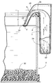
図1は、濾過装置を水槽にセットした場合の斜視図、図2は、図1の2矢視の濾過装置の正面図、図3は、図2の3線矢視の濾過装置の平面図、図4は、図3の4−4線に沿う濾過装置の平面図、図5は、図2の5−5線に沿う断面図、図6は、図2の6−6線に沿う断面図、図7は、図2の7−7線に沿う断面図、図8は、図2の8−8線に沿う断面図、図9は、濾過ケースの取付凹部と水ポンプ取付凸部の分解斜視図、図10(A)(B)および(C)は、水ポンプの濾過ケースへの組付過程図を示す図、図11(A)および(B)は、図10の11(A)−11(A)および11(B)−11(B)に沿う断面図である。
1 is a perspective view when the filtration device is set in a water tank, FIG. 2 is a front view of the filtration device as seen from the
図1に示すように、本実施例にかかる外部式濾過装置は、水槽Vに外掛けして使用される型式のものであり、水槽Vの壁面の外掛けされる濾過本体Fと、水槽V内の水を濾過本体F内に循環させる水ポンプPとより構成される。 As shown in FIG. 1, the external filtration apparatus according to the present embodiment is of a type that is used by being hung on a water tank V. The filtration main body F that is hung on the wall surface of the water tank V, and the water tank V It is comprised from the water pump P which circulates the inside water in the filtration main body F.
濾過本体Fは、濾過ケース1と、その内部に抜差可能に設けられる濾過エレメント15と、吸水部4および放水管3とを備えている。
The filtration body F includes a
濾過ケース1は硬質合成樹脂材により形成されて、その上面に出入口5を開口した扁平な箱状に形成されており、その前面には、その全幅にわたって下向きのフック状をなす引掛け部6が一体に形成され、この引掛け部6は、図1に示すように、水槽Vの上縁部に着脱可能に外掛けできるようにされる。図2〜4に示すように、濾過ケース1内には、その左右幅方向の一側に偏らせて、該濾過ケース1内を左右に仕切る、上下方向の仕切壁7が設けられており、この仕切壁7により、濾過ケース1の幅方向の一側の吸水部4に、貯水室8が形成されると共にその他側に、貯水室8よりも容積の大きい濾過室10が形成されている。図4,5に示すように、仕切壁7には、貯水室8と濾過室10とを連通する上下に長い流水口11が開口され、さらに前記仕切壁7の上部には、流入口9が開口され、貯水室8内の貯留水の上水は、この流入口9を通過し、濾過エレメント15を通らずに濾過室10へと流入できるようになっている。
The
図1,2および図4,5に示すように、濾過ケース1の底壁一側には、凹部2が形成され、この凹部2に前記水ポンプPが収められる。この水ポンプPの吸込口Psおよび吐出口Pdは、いずれも前記貯水室8の下部に臨んでいる。図5に示すように、前記吸込口Psには、貯水室8内を縦通する第1の吸込管30aの下端が接続され、この第1の吸込管30aの上端には第2の吸込管30bの基端が接続される。第2の吸込管30bはエルボ状に湾曲して濾過ケース1外に延出されて水槽V内に垂下され、その下端にストレーナ29が接続されている。
As shown in FIGS. 1, 2 and 4, 5, a
図4に示すように、水ポンプPの吐出口Pdは、貯水室8の下部に直接連通されている。したがって、水ポンプPの運転によれば、図4,5矢印aに示すように、水槽V内の未浄化水は、ストレーナ29により第2の吸込管30bを経て第1の吸込管30aに吸引されたのち、吐出口Pdより貯水室8に吐出して、そこに貯水される。
As shown in FIG. 4, the discharge port Pd of the water pump P is in direct communication with the lower part of the
図4に明瞭に示すように、濾過室10内には、その上部開口から、濾過エレメント15および放水管3が互いに並列して各別に着脱自在に取り付けられる。
As clearly shown in FIG. 4, the
また、濾過ケース1の濾過室10の前面には、放水管3の一方の側壁(仕切壁)3aと前記仕切壁7間に、スカート状の流水壁12が一体に形成されている。この流水壁12は、図1に示すように、その縦断面が外方に向かって凸の湾曲状をなしており、この流水壁12の上縁には、略水平なオーバフロー壁13が形成され、濾過室10内を溢れた水は、このオーバフロー壁13を超え、流水壁12に沿って流下し、水槽V内に戻されるようになっている。濾過室10内の濾過エレメント15は、合成樹脂製の長方形の濾過板により形成される。
Further, a skirt-shaped flowing
濾過ケース1の左右方向の一側(図1左側)に、抜差自在に装着される放水管3は、下方に向かって漸次先細りの角筒状に形成されており、濾過エレメント15に隣接する側壁3aは、濾過室10と、この放水管3とを水密状に離隔する仕切壁を形成している。また、放水管3の側壁(仕切壁)3aの下部には、入口22(図4,6参照)が開口され、この入口22を通して放水管3内は前記浄化室19に連通される。放水管3は、その上部に、濾過ケース1の流水壁12に沿うようなノーズ部分23が一体に形成され、このノーズ部分23の下端に放出口24(図1,5,6参照)が下向きに開口されている。そして、図4に示すように、濾過室10内で、濾過された水は、入口22を通って放水管3内に入り、放水口24より水槽V内に戻されるようになっている。
The
放水管3のノーズ部分23は、上下方向に延びており、放水管3の上壁3bと、その放水口24との間には、上下方向に所定の距離があけられており、濾過本体Fを水槽Vに外掛けしたとき、放水管3の上壁3bと、放水口24間には、落差H(図5参照)が形成され、この落差Hによるサイホン作用により、濾過本体F内の浄化水は、水槽V内に戻されるようになっている。また、水ポンプPの運転によれば、水槽V内の未浄化水は、貯水室8内に貯水される。
The
つぎに、水ポンプPの濾過ケース1への取付構造について説明する。
Below, the attachment structure to the
図4に示すように、濾過ケース1の貯水室8の下方には、凹部2が形成され、この凹部2に水ポンプPが収容される。貯水室8の底壁には、その下方に開口する、水ポンプPを着脱自在に取り付けるための、上壁を有する中空円筒状の取付凹部35が形成されている。図9に示すように、取付凹部35の上面には、水ポンプPの吸込口Psを第1の吸込管30aに連通させる吸込側連通口36が開口され、また、その側面には、水ポンプPの吐出口Pdを貯水室8に連通させる吐出側連通口37開口されている。
As shown in FIG. 4, a
また、この取付凹部35の側面には、バヨネットの雌を構成する一対の円弧状係合溝38,38が径方向に一体に形成され、これらの係合溝38,38の対角端には、後述するバヨネットの雄を構成する係合突起(水ポンプPの後述の取付凸部41に形成)が挿入される入口38i,38iが形成されている。また、取付凹部35の上面中央部には、水ポンプPのポンプ軸45を受ける軸受部39が形成されている
また、図9に示すように、水ポンプPは、モータ(図示せず)の収容される四角なブロック状のポンプ本体40の一面に、中空円筒状の取付凸部41が形成される。この取付凸部41の外周面には、2条の環状パッキン溝42,42が形成され、これらのパッキン溝42,42に、ゴムなどの弾性材よりなるパッキンリング43,43がそれぞれ嵌着される。水ポンプPのポンプ軸45は、ポンプ本体40の中央を上方に延長されて前記取付凹部35に収容されるポンプ羽根46が固定される。ポンプ軸45は取付凸部41を通って外部に延長されており、その外端に、ゴムなどの弾性体よりなるキャップ状の軸受47が一体に嵌着されている。
In addition, a pair of arc-
濾過ケース1側の取付凹部35と、水ポンプP側の取付凸部41には、それらを着脱可能に一体に係合する係合手段Eが設けられる。この係合手段Eは、取付凹部35の内周面の径方向に形成される一対の円弧状係合溝(バヨネットの雌部材)38,38と、取付凸部41の外周面の径方向に形成される一対の円弧状係合突起(バヨネットの雄部材)48,48とより構成され、一対の係合溝38,38の一端および他端に形成した入口端38i,38iに係合突起48,48を位置させたのち、該係合突起48,48を係合溝38,38にそれぞれ挿嵌させることにより、係合突起48,48を係合溝38,38に係合させることができる。
The
つぎに、図10,11を参照して、水ポンプPを、濾過ケース1の底壁に組み付ける手順について説明する。
Next, a procedure for assembling the water pump P to the bottom wall of the
(1) 図10(A)に示すように、濾過ケース1の底壁の取付凹部35に、水ポンプPの取付凸部41を対向位置させる。このとき、水ポンプPは、正規の組み付け位置に対して、ポンプ軸45まわりに約90°位相がずらしてある。
(1) As shown in FIG. 10 (A), the mounting
(2) つぎに、水ポンプPを濾過ケース1に向けて押圧すれば、図10(B)、図11(A)に示すように、取付凹部35内に取付凸部41が嵌合される。この嵌合状態では2条のパッキンリング43,43は、取付凹部35と取付凸部41との間を液密に封緘すると共に、水ポンプPを濾過ケース1に摩擦支持する。
(2) Next, when the water pump P is pressed toward the
(3) つぎに、図10(C)、図11(B)に示すように、水ポンプPを、濾過ケース1に対してポンプ軸45まわりに約90°回動させれば、バヨネットを構成する、一対の係合突起48,48と、一対の係合溝38,38とは相互に係合して、水ポンプPを濾過ケース1の底壁の凹部2に堅固に液密に支持することができる。
(3) Next, as shown in FIGS. 10 (C) and 11 (B), if the water pump P is rotated about 90 ° around the
そして、前記(1) 〜(3) の水ポンプPの濾過ケース1への組付操作は、操作者が水ポンプPのポンプ本体40を把持してワンタッチにて行うことができる。
The operation of assembling the water pump P to the
なお、図中、32は、水槽V内の底部に敷設される、大磯などの小石、33は濾過ケース1の下部に出入れ可能に設けられる弾性材よりなる支持片であり、その先端が水槽Vの壁面に当接されて、濾過ケース1の振動を緩衝吸収することができ、また該濾過ケース1の姿勢を制御する。
In the figure, 32 is a pebble such as a large coral laid on the bottom of the water tank V, 33 is a support piece made of an elastic material that can be put in and out of the lower part of the
この濾過装置を使用するに当たっては、図1に示すように、濾過ケース1内に、濾過エレメント15および放水管3を設けた濾過本体1を、水槽Vの壁面に外掛けする。
In using this filtration device, as shown in FIG. 1, the
ここで、水ポンプPを運転すると、水槽V内の未浄化水は、この水ポンプPにより吸い上げられ、ストレーナ29、第1、第2の吸込管30b,30aを通って水ポンプPに吸い込まれ(図5、矢印a)、貯水室8に圧送される。貯水室8に入った水は、前記仕切壁7の流水口11を通って濾過室10に流入し(図4、矢印b)、さらに次第にその水位を上げ、その上位の水は、仕切壁7の上縁の流入口9をオーバフローして、濾過ケース1の中央部に形成される濾過室10へと流れる(図4、矢印b′)。
Here, when the water pump P is operated, unpurified water in the water tank V is sucked up by the water pump P, and sucked into the water pump P through the
前述したように、濾過室10内に流入した水は、
(1) 図1,3の矢印eに示すように、濾過エレメント15を通過することなく、すなわち濾過されることなく、そのままオーバフロー壁13を溢流し、流水壁12を伝わって水槽V内に戻される、第1の流れの水と、
(2) 前記落差Hにより生じるサイホン作用による吸引力を、放出管3の入口22を通して受けることにより、図4の矢印c,dに示すように、仕切壁7に開口した流水口11より未浄化室18内に入り、濾過エレメント15を通過して濾過されたのち、浄化室19へと流れ、該室19を下方へと流れて入口22を通って放水管3へと導かれる、第2の流れの水とに分流される。
As described above, the water flowing into the
(1) As shown by the arrow e in FIGS. 1 and 3, the
(2) By receiving the suction force due to the siphon action generated by the head H through the
ところで、前記(2) において、放出管3に流入した、浄化された第2の流れの水は、図6の矢印dに示すように、ノーズ部分23の落差Hによるサイホン作用で水槽V内に戻される。一方、前記(1) において、濾過室10よりオーバフロー壁13を溢流した、第1の流れの水は、図3の矢印eに示すように、濾過されないまま、流水壁112に沿って水槽V内に直接戻される。したがって貯水室8から濾過室10に流入した水は、その一部(第2の流れの水)が濾過エレメント15を通過して濾過され、また、その残部(第1の流れの水)は濾過エレメント15を通過することなく水槽V内に戻され、しかも濾過エレメント15を通過する水は、それを通過しない水よりも流れ抵抗が大きいため、濾過エレメント15を通過する水は、その流量および流速が抑えられ、その結果、濾過エレメント15の目詰まりが少なくなると共に、その濾過エレメント15での好気性微生物の繁殖を促進して、該濾過エレメント15による、水の濾過作用と、好気性微生物による水の有機的浄化作用を共に高めることができる。
By the way, in the above (2), the purified second flow of water that has flowed into the
以上、本発明の実施例について説明したが、本発明はその実施例に限定されることなく、本発明の範囲内で種々の実施例が可能である。 As mentioned above, although the Example of this invention was described, this invention is not limited to the Example, A various Example is possible within the scope of the present invention.
たとえば、前記サイホン作用に依存せず、水ポンプにより濾過室内に送給された水を濾過エレメントにより濾過するようにした、濾過装置にも適用可能であり、また前記実施例では、水ポンプの取付凸部の外周に2条のパッキンリングを設けているが、該取付凸部には3条以上のパッキンリングを設けてもよい。 For example, the present invention can be applied to a filtering device that does not depend on the siphon action and filters the water fed into the filter chamber by the water pump by the filter element. In the embodiment, the water pump is attached. Although two packing rings are provided on the outer periphery of the convex portion, three or more packing rings may be provided on the mounting convex portion.
10……………濾過室
15……………濾過エレメント
35……………取付凹部
38……………係合溝
39……………軸受部
40……………ポンプ本体
41……………取付凸部
42……………パッキン溝
43……………パッキンリング
45……………ポンプ軸
47……………軸受
48……………係合突起
V……………水槽
10 ............ Filtering
Claims (2)
濾過ケース(1)の底壁に円筒状取付凹部(35)を設け、この取付凹部(35)に水ポンプ(P)のポンプ本体(40)に形成した円筒状取付凸部(41)を複数のパッキンリング(43)を介して回動可能に液密に嵌合し、それらの嵌合部から離れた位置で、取付凹部(35)には、一対の円弧状係合溝(38)を径方向に形成する一方、取付凸部(41)には、一対の円弧状係合突起(48)を径方向に形成し、
取付凸部(41)を取付凹部(35)に嵌合した状態で、ポンプ本体(40)を濾過ケース(1)に対して所定角度回動させることにより係合溝(38)と係合突起(48)とを相互に係合させ、
さらに、取付凹部(35)の中央部には、ポンプ本体(40)より片持状に突出するポンプ軸(45)の外端に嵌着した弾性体よりなる軸受(47)を回転自在に支承する軸受部(39)を形成したことを特徴とする、水槽用濾過装置の水ポンプ取付構造。 It is a water pump mounting structure for a filtration device in which unpurified water in the water tank (V) is sucked into the filtration chamber (10), filtered through the filter element (15), and refluxed into the water tank (V). And
Filtration cylindrical mounting recesses (35) provided in the bottom wall of the over-case (1), the cylindrical attachment member formed in the pump body (40) of the water pump (P) to the mounting recess (35) and (41) A pair of arcuate engagement grooves (38) are fitted in the mounting recess (35) at a position remote from the fitting portions so as to be pivotable and fluid-tight through a plurality of packing rings (43). Is formed in the radial direction on the mounting convex portion (41), and a pair of arcuate engagement protrusions (48) are formed in the radial direction.
The engagement groove (38) and the engagement protrusion are obtained by rotating the pump body (40) by a predetermined angle with respect to the filtration case (1) in a state where the attachment protrusion (41) is fitted in the attachment recess (35). (48) with each other,
Further, a bearing (47) made of an elastic body fitted on the outer end of the pump shaft (45) protruding in a cantilever manner from the pump body (40) is rotatably supported at the center of the mounting recess (35). A water pump mounting structure for a water tank filtration device, wherein a bearing portion (39) is formed.
Priority Applications (1)
| Application Number | Priority Date | Filing Date | Title |
|---|---|---|---|
| JP2004263285A JP4615940B2 (en) | 2004-09-10 | 2004-09-10 | Water pump mounting structure for water tank filtration device |
Applications Claiming Priority (1)
| Application Number | Priority Date | Filing Date | Title |
|---|---|---|---|
| JP2004263285A JP4615940B2 (en) | 2004-09-10 | 2004-09-10 | Water pump mounting structure for water tank filtration device |
Publications (2)
| Publication Number | Publication Date |
|---|---|
| JP2006075092A JP2006075092A (en) | 2006-03-23 |
| JP4615940B2 true JP4615940B2 (en) | 2011-01-19 |
Family
ID=36155064
Family Applications (1)
| Application Number | Title | Priority Date | Filing Date |
|---|---|---|---|
| JP2004263285A Expired - Fee Related JP4615940B2 (en) | 2004-09-10 | 2004-09-10 | Water pump mounting structure for water tank filtration device |
Country Status (1)
| Country | Link |
|---|---|
| JP (1) | JP4615940B2 (en) |
Families Citing this family (1)
| Publication number | Priority date | Publication date | Assignee | Title |
|---|---|---|---|---|
| CN114451346A (en) * | 2022-02-08 | 2022-05-10 | 连云港市瑞日实业发展有限公司 | Wall-mounted water treatment device for aquarium and treatment method thereof |
Citations (4)
| Publication number | Priority date | Publication date | Assignee | Title |
|---|---|---|---|---|
| JPH0374582U (en) * | 1989-11-27 | 1991-07-26 | ||
| JPH0670660A (en) * | 1992-05-28 | 1994-03-15 | Tominaga Jushi Kogyosho:Kk | Filtration apparatus for water tank |
| JP2000073421A (en) * | 1998-08-31 | 2000-03-07 | Kvk Corp | Piping connecting structure of hydrant |
| JP2002095719A (en) * | 2000-09-26 | 2002-04-02 | Toto Ltd | Bubble generating bathtub |
-
2004
- 2004-09-10 JP JP2004263285A patent/JP4615940B2/en not_active Expired - Fee Related
Patent Citations (4)
| Publication number | Priority date | Publication date | Assignee | Title |
|---|---|---|---|---|
| JPH0374582U (en) * | 1989-11-27 | 1991-07-26 | ||
| JPH0670660A (en) * | 1992-05-28 | 1994-03-15 | Tominaga Jushi Kogyosho:Kk | Filtration apparatus for water tank |
| JP2000073421A (en) * | 1998-08-31 | 2000-03-07 | Kvk Corp | Piping connecting structure of hydrant |
| JP2002095719A (en) * | 2000-09-26 | 2002-04-02 | Toto Ltd | Bubble generating bathtub |
Also Published As
| Publication number | Publication date |
|---|---|
| JP2006075092A (en) | 2006-03-23 |
Similar Documents
| Publication | Publication Date | Title |
|---|---|---|
| JP5584714B2 (en) | Air-driven filter device | |
| JP2585671Y2 (en) | Ornamental fish tank filtration device | |
| US3994811A (en) | Protein skimmer and carbon filtration replaceable unit | |
| JP2518993B2 (en) | Filter for aquarium | |
| US3746168A (en) | Aquarium filtration indicator | |
| JP5793785B1 (en) | Water filtration device for aquatic aquarium | |
| JP3605582B2 (en) | External filtration device | |
| US3746169A (en) | Aquarium filtration device | |
| JP4615940B2 (en) | Water pump mounting structure for water tank filtration device | |
| JP5497378B2 (en) | Internal filtration device | |
| US6527949B1 (en) | Landscaping pond system | |
| JP5745392B2 (en) | Internal filtration device | |
| JP5292042B2 (en) | Water tank filter | |
| JP6338236B2 (en) | Internal filtration device | |
| JP3561300B2 (en) | Filter for submersible pump and air pump | |
| JP6737452B2 (en) | Internal filtration device | |
| JP4079941B2 (en) | Filter medium accommodation unit in water tank outer filtration apparatus and water tank outer filtration apparatus comprising the filter medium accommodation unit | |
| JP3975221B2 (en) | Bottom filtration device | |
| JP4145688B2 (en) | Upper filter | |
| JP2016189753A (en) | Outside hanging type filtration device | |
| JP3650345B2 (en) | Water tank filter | |
| JP4530908B2 (en) | Saltwater fish tank with salt dripping prevention tool | |
| JP5780922B2 (en) | Internal filtration device | |
| JPS6344826A (en) | Filter device for water tank of acquarium fish | |
| JPH037517A (en) | Filter device |
Legal Events
| Date | Code | Title | Description |
|---|---|---|---|
| A621 | Written request for application examination |
Free format text: JAPANESE INTERMEDIATE CODE: A621 Effective date: 20070419 |
|
| A977 | Report on retrieval |
Free format text: JAPANESE INTERMEDIATE CODE: A971007 Effective date: 20080922 |
|
| A131 | Notification of reasons for refusal |
Free format text: JAPANESE INTERMEDIATE CODE: A131 Effective date: 20100414 |
|
| A521 | Written amendment |
Free format text: JAPANESE INTERMEDIATE CODE: A523 Effective date: 20100604 |
|
| A131 | Notification of reasons for refusal |
Free format text: JAPANESE INTERMEDIATE CODE: A131 Effective date: 20100721 |
|
| A521 | Written amendment |
Free format text: JAPANESE INTERMEDIATE CODE: A523 Effective date: 20100817 |
|
| TRDD | Decision of grant or rejection written | ||
| A01 | Written decision to grant a patent or to grant a registration (utility model) |
Free format text: JAPANESE INTERMEDIATE CODE: A01 Effective date: 20101006 |
|
| A01 | Written decision to grant a patent or to grant a registration (utility model) |
Free format text: JAPANESE INTERMEDIATE CODE: A01 |
|
| A61 | First payment of annual fees (during grant procedure) |
Free format text: JAPANESE INTERMEDIATE CODE: A61 Effective date: 20101021 |
|
| R150 | Certificate of patent or registration of utility model |
Free format text: JAPANESE INTERMEDIATE CODE: R150 |
|
| FPAY | Renewal fee payment (event date is renewal date of database) |
Free format text: PAYMENT UNTIL: 20131029 Year of fee payment: 3 |
|
| R250 | Receipt of annual fees |
Free format text: JAPANESE INTERMEDIATE CODE: R250 |
|
| R250 | Receipt of annual fees |
Free format text: JAPANESE INTERMEDIATE CODE: R250 |
|
| R250 | Receipt of annual fees |
Free format text: JAPANESE INTERMEDIATE CODE: R250 |
|
| R250 | Receipt of annual fees |
Free format text: JAPANESE INTERMEDIATE CODE: R250 |
|
| LAPS | Cancellation because of no payment of annual fees |