[go: up one dir, main page]

JP4613697B2 - Bathtub with water jet - Google Patents

Bathtub with water jet Download PDF

Info

Publication number
JP4613697B2
JP4613697B2 JP2005154691A JP2005154691A JP4613697B2 JP 4613697 B2 JP4613697 B2 JP 4613697B2 JP 2005154691 A JP2005154691 A JP 2005154691A JP 2005154691 A JP2005154691 A JP 2005154691A JP 4613697 B2 JP4613697 B2 JP 4613697B2
Authority
JP
Japan
Prior art keywords
water
bathtub
flow
valve
jet
Prior art date
Legal status (The legal status is an assumption and is not a legal conclusion. Google has not performed a legal analysis and makes no representation as to the accuracy of the status listed.)
Expired - Fee Related
Application number
JP2005154691A
Other languages
Japanese (ja)
Other versions
JP2006325993A (en
Inventor
良泰 伊藤
一雅 六嶋
範行 北地
尚紀 柴田
重行 山口
仁史 北村
康成 前田
Current Assignee (The listed assignees may be inaccurate. Google has not performed a legal analysis and makes no representation or warranty as to the accuracy of the list.)
Panasonic Corp
Panasonic Electric Works Co Ltd
Original Assignee
Panasonic Corp
Matsushita Electric Works Ltd
Priority date (The priority date is an assumption and is not a legal conclusion. Google has not performed a legal analysis and makes no representation as to the accuracy of the date listed.)
Filing date
Publication date
Application filed by Panasonic Corp, Matsushita Electric Works Ltd filed Critical Panasonic Corp
Priority to JP2005154691A priority Critical patent/JP4613697B2/en
Publication of JP2006325993A publication Critical patent/JP2006325993A/en
Application granted granted Critical
Publication of JP4613697B2 publication Critical patent/JP4613697B2/en
Anticipated expiration legal-status Critical
Expired - Fee Related legal-status Critical Current

Links

Images

Landscapes

  • Percussion Or Vibration Massage (AREA)

Description

本発明は、入浴しながら水流により身体のマッサージができる水流噴出装置付浴槽に関するものである。 The present invention relates to a bathtub with a water jet device that can massage a body by a water flow while bathing.

従来から浴槽に水流(浴水又は気泡入り浴水)を噴出して浴槽に入浴している人に衝突させてマッサージすることが行われている。このような従来例として例えば特許文献1が知られている。   Conventionally, a water flow (bath water or bubble bath water) is jetted into a bathtub so as to collide with a person bathing in the bathtub and massaged. For example, Patent Document 1 is known as such a conventional example.

この特許文献1に示された従来例にあっては、浴槽に設けた噴出口から一定方向に水流を噴出させて入浴者の身体の一部に水流を当てるものであり、水流はポンプをオンすることで噴出し、ポンプをオフすることで噴出停止するようになっており、一定の流速の水流を身体の一箇所に連続して当てるようになっている。   In the conventional example shown in Patent Document 1, a water flow is sprayed from a jet outlet provided in a bathtub in a certain direction so as to apply a water flow to a part of a bather's body. The jetting is stopped, and the jetting is stopped by turning off the pump. A water flow having a constant flow velocity is continuously applied to one part of the body.

しかしながら、このように一定の流速の水流を身体の一箇所に連続して当てるものにおいては、マッサージとしては強弱のめりはりがなく、人の指先でマッサージするようなマッサージ効果を得ることができなかった。
特開2003−250854号公報
However, in the case where the water flow at a constant flow rate is continuously applied to one part of the body in this way, there is no strength and weakness as a massage, and it has not been possible to obtain a massage effect that massages with a fingertip of a person .
JP 2003-250854 A

本発明は上記の点に鑑みなされたものであって、その目的とするところは、人の指でマッサージするようなマッサージ感を水流により得ることができて入浴しながら効果的なマッサージが行える水流噴出装置付浴槽を提供することにある。 The present invention has been made in view of the above, it is an object of water capable of performing effective massage while bathing can be obtained by water massage feeling as to massage a human finger The object is to provide a bathtub with an ejection device .

上記課題を解決するために本発明にあっては、浴槽1内の浴水中に入浴している入浴者の下半身に浴水の水流によりマッサージするための水流噴出装置付浴槽であって、浴槽1に、入浴者Mの下半身における心臓からの距離が異なる複数個所に浴槽1内の浴水を水流として間欠的に噴出するための複数の噴出口2を設け、上記複数の噴出口2からの噴射が、心臓から遠い方に位置する噴出口2から心臓に近い方の噴出口2にかけて順番に水流を間欠的に噴射し、且つ、各噴出口2からの水流の間欠的な噴出の際に該間欠噴出区間の始めにゆっくりと噴出を開始して次第に流速を速く且つ間欠噴出区間の終りに次第に流速が遅くなってゆっくりと噴出が止まるようにするための流速可変手段3を設け、該流速可変手段3を、ポンプ6と噴出口2との間に設けた電動弁7により構成し、該電動弁7を、弁本体8に設けた孔9に嵌め込まれたモータ10により回動する回動弁体11と、回動弁体11に設けた水の供給用の弁口12と、孔9の壁面における弁口12の回転軌跡の複数個所に対応する位置に隔設して設けた複数の流出口13とで構成し、回動弁体11の回動により弁口12が複数の流出口13と順番に連通し、且つ、弁口12の各流出口13とが連通する際回動弁体11の回動により連通状態が変化するものであることを特徴とするものである。 In order to solve the above-described problems, the present invention provides a bathtub with a water jet device for massaging the lower body of a bather bathing in the bath water in the bath 1 with the water flow of the bath water. In addition, a plurality of spouts 2 for intermittently ejecting the bath water in the bathtub 1 as a water flow are provided at a plurality of locations at different distances from the heart in the lower body of the bather M, and jets from the plurality of spouts 2 However, the water flow is intermittently ejected in order from the spout 2 located far from the heart to the spout 2 near the heart, and the water flow from each spout 2 is intermittently ejected. The flow rate variable means 3 is provided for slowly starting the ejection at the beginning of the intermittent ejection section, gradually increasing the flow velocity, and gradually decreasing at the end of the intermittent ejection section to stop the ejection slowly. Means 3 is connected to pump 6 and spout 2 The motor-operated valve 7 is provided between the rotary valve body 11 and the rotary valve body 11. The motor-operated valve 7 is rotated by a motor 10 fitted in a hole 9 provided in the valve body 8. A water supply valve port 12 and a plurality of outlets 13 provided at positions corresponding to a plurality of positions of the rotation path of the valve port 12 on the wall surface of the hole 9. The valve port 12 communicates with the plurality of outlets 13 in turn by the rotation of the valve 11, and the communication state changes due to the rotation of the rotary valve body 11 when the valve port 12 communicates with each of the outlets 13 of the valve port 12. It is characterized by being.

このように入浴者Mの下半身における心臓からの距離が異なる複数個所に浴槽1内の浴水を水流として間欠的に噴出するための複数の噴出口2を設け、上記複数の噴出口2からの噴射が、心臓から遠い方に位置する噴出口2から心臓に近い方の噴出口2にかけて順番に水流を間欠的に噴射するので、浴槽1に入浴者Mが一般的な入浴姿勢をとって入浴した場合に、浴槽1内の浴水中に入浴している入浴者Mの下半身における心臓から遠い方(足先に近い方)に位置する噴出口2から心臓に近い方の噴出口2にかけて順番に浴水の水流を噴出することになり、これにより、入浴者Mの下半身におけるリンパ管を心臓から遠い方から心臓に近い方にかけて順番に揉み上げて、リンパ管内のリンパ液の、心臓から遠い方から心臓側に向けての流れを促進し、リンパ液が足先や手先側に逆流したり、途中で滞留したりしないようにできて、効果的なリンパマッサージができる。 In this way, a plurality of spouts 2 for intermittently spouting the bath water in the bathtub 1 as a water flow are provided at a plurality of locations where the distance from the heart in the lower body of the bather M is different. The jets are intermittently jetted in sequence from the jet outlet 2 located farther from the heart to the jet outlet 2 closer to the heart, so that the bather M takes a general bathing posture in the bath 1 In this case, the lower half of the bather M bathing in the bath water in the bathtub 1 in order from the spout 2 located farther from the heart (closer to the toes) to the spout 2 closer to the heart The water flow of the bath water will be spouted, so that the lymph vessels in the lower body of the bather M are swollen in order from the far side from the heart to the near side of the heart, and the lymph fluid in the lymph vessels from the far side to the heart The flow towards the side Proceeds to, or flows back into the toes and fingers side lymph, and can prevent or staying in the middle, it is effective lymphatic massage.

また、この心臓から遠い入浴者Mの下半身におけるリンパマッサージを行うに当たって、各噴出口2からの水流の間欠的な噴出の際に該間欠噴出区間の始めにゆっくりと噴出を開始して次第に流速を速く且つ間欠噴出区間の終りに次第に流速が遅くなってゆっくりと噴出が止まるようにするための流速可変手段3を設けたので、ゆっくりともみ始めて次第に強く揉み、次第に押す力を弱めながら揉み終わるという身体を指でマッサージする際のもみ動作と同じような揉み動作を水流により得ることができて効果的なマッサージが実現できる。   In addition, when performing lymphatic massage on the lower body of the bather M far from the heart, when the water flow from each of the spouts 2 is intermittently spouted, the spout is slowly started at the beginning of the intermittent spout section and the flow rate is gradually increased. Since the flow rate variable means 3 is provided to make the flow stop slowly and slowly stop at the end of the intermittent ejection section, the body begins to slowly squeeze and gradually squeeze, gradually squeezing while weakening the pushing force It is possible to obtain a massage motion similar to the scissors motion when massaged with a finger by means of water flow, and an effective massage can be realized.

また、流速可変手段3を、ポンプ6と噴出口2との間に設けた電動弁7により構成し、該電動弁7を、弁本体8に設けた孔9に嵌め込まれたモータ10により回動する回動弁体11と、回動弁体11に設けた水の供給用の弁口12と、孔9の壁面における弁口12の回転軌跡の複数個所に対応する位置に隔設して設けた複数の流出口13とで構成し、回動弁体11の回動により弁口12が複数の流出口13と順番に連通し、且つ、弁口12の各流出口13とが連通する際回動弁体11の回動により連通状態が変化するものであるから、回動弁体11を回動して弁口12と流出口13との連通と非連通とを繰り返すことで噴出口2から水流を間欠的に噴出することができるだけでなく、回動弁体11が回動して弁口12が流出口13と連通開始する際に連通面積が次第に広くなっていくとともに連通終了の際に連通面積が次第に狭くなっていき、これにより最初はゆっくりと次第に速くなり、最後は次第に遅くなってゆっくりと終了するという水流を噴出口2から噴出して効果的なマッサージが実現できるものである。   Further, the flow velocity variable means 3 is constituted by an electric valve 7 provided between the pump 6 and the jet outlet 2, and the electric valve 7 is rotated by a motor 10 fitted in a hole 9 provided in the valve body 8. The rotating valve body 11 to be provided, the water supply valve opening 12 provided in the rotating valve body 11, and provided at positions corresponding to a plurality of locations of the rotation locus of the valve opening 12 on the wall surface of the hole 9. When the rotary valve body 11 is rotated, the valve port 12 communicates with the plurality of outlets 13 in order and the outlets 13 of the valve port 12 communicate with each other. Since the communication state is changed by the rotation of the rotating valve body 11, the nozzle 2 is rotated by repeating the communication and non-communication between the valve port 12 and the outlet 13 by rotating the rotating valve body 11. Not only can the water flow be ejected intermittently, but also the rotating valve body 11 rotates and the valve port 12 starts to communicate with the outlet port 13. As the communication area gradually increases, the communication area gradually decreases at the end of communication.This causes the water flow to start slowly and gradually, and finally slowly and slowly. An effective massage can be realized by ejecting from the outlet 2.

また、水流を噴出する間欠噴出区間の始めにゆっくりと噴出を開始して次第に流速が速くなり、最大流速に達した時点をピークとして次第に流速が遅くなってゆっくりと噴出が止まるようにすることが好ましい。   In addition, the flow rate gradually increases at the beginning of the intermittent jet section where the water flow is jetted, and the flow rate gradually increases. preferable.

このような構成とすることで、入浴者Mの身体の一部に水流を当ててマッサージするに当たり、該当する身体の部位に対して当該部位を指でゆっくりと押して最大の押圧後すぐにゆっくりと引くという指による揉みマッサージと同じ動作を水流を当てて実現でき、より効果的なマッサージが実現できる。   By adopting such a structure, when applying massage to a part of the body of the bather M, slowly press the part against the corresponding part of the body with a finger and immediately immediately after the maximum press. The same action as a massage massage with a finger can be realized by applying water flow, and a more effective massage can be realized.

また、水流を噴出する間欠噴出区間の始めにゆっくりと噴出を開始して次第に流速が速くなり、最大流速に達すると該最大流速を一定時間継続し、最大流速を一定時間継続した後に次第に流速が遅くなってゆっくりと噴出が止まるようにすることが好ましい。   In addition, the flow rate gradually increases at the beginning of the intermittent ejection section where water flow is ejected, and the flow rate gradually increases.When the maximum flow rate is reached, the maximum flow rate continues for a certain period of time, and after the maximum flow rate continues for a certain period of time, the flow rate gradually increases. It is preferable that the jetting is stopped slowly and slowly.

このような構成とすることで、入浴者Mの身体の一部に水流を当ててマッサージするに当たり、該当する身体の部位に対して当該部位を指でゆっくりと押して最大の押圧に達するとこれを継続しその後ゆっくりと引くという指によるマッサージと同じ動作を水流を当てて実現でき、より効果的なマッサージが実現できる。   By adopting such a configuration, when applying massage to a part of the body of the bather M, the part is slowly pushed with a finger against the part of the corresponding body and the maximum pressure is reached. The same action as a finger massage that is continued and then slowly pulled can be achieved by applying water flow, and a more effective massage can be realized.

また、入浴者Mの身体の異なる部位にそれぞれ水流を間欠的に噴出するための複数の噴出口2を浴槽1に設け、上記弁本体8の孔9の壁面における弁口12の回動軌跡の複数箇所に対応する位置に複数の流出口13を隔設し、弁口12の周方向の長さを周方向に隣接する流出口13間の周方向の長さよりも長くすることが好ましい。   In addition, a plurality of spouts 2 are provided in the bathtub 1 for intermittently ejecting water flows to different parts of the body of the bather M, and the rotation trajectory of the valve opening 12 on the wall surface of the hole 9 of the valve body 8 is described. It is preferable to provide a plurality of outlets 13 at positions corresponding to a plurality of locations, and to make the circumferential length of the valve port 12 longer than the circumferential length between the outlets 13 adjacent in the circumferential direction.

このような構成とすることで、一つのポンプ6から供給される水を複数の流出口13から順番に繰り返しながら水流を噴出して入浴者Mの身体の異なる部位を順番にマッサージでき、しかも、上記異なる部位を水流によりマッサージする際に、ある流出口13から噴出する水流が次第に遅くなって行く動作に並行して他の流出口13からゆっくりと水流が噴出し始めて次第に速くなるという動作が行われ、身体の異なる部位を水流でマッサージするに当たって異なる部位のマッサージが途切れることなくめりはりを持たせて連続して行えることになる。   By having such a configuration, it is possible to massage the different parts of the body of the bather M in order by ejecting the water flow while sequentially repeating the water supplied from one pump 6 from the plurality of outlets 13, When massaging the different parts with a water flow, an operation is performed in which the water flow slowly starts to be ejected from another outlet 13 in parallel with the operation in which the water flow ejected from one outlet 13 gradually slows down. In other words, when massaging different parts of the body with a water stream, the massage of the different parts can be performed continuously without interruption.

本発明にあっては、浴槽内の浴水中に入浴しているリラックスした状態で、心臓から遠い入浴者の下半身に浴槽内の浴水を水流として間欠的に当てて、入浴者の下半身における心臓から遠い方に位置する噴出口から心臓に近い方の噴出口にかけて順番に水流を噴出し、これにより浴槽内の浴水中に入浴している入浴者の下半身におけるリンパ管を心臓から遠い方から心臓に近い方にかけて順番に揉み上げて、リンパ管内のリンパ液の、心臓から遠い方から心臓側に向けての流れを促進し、リンパ液が足先や手先側に逆流したり、途中で滞留したりしないようにできて、効果的なリンパマッサージができる。 In the present invention, in the relaxed state bathing in the bath water in the bathtub, the bath water in the bathtub is intermittently applied as a water flow to the lower body of the bather far from the heart, and the heart in the lower body of the bather The water flow is spouted in sequence from the spout located far from the spout to the spout near the heart, so that the lymphatic vessels in the lower body of the bather bathing in the bath water in the bathtub from the heart far from the heart Squeeze in order toward the side closer to, and promote the flow of lymph in the lymphatic vessels from the far side of the heart to the heart side, so that the lymph does not flow back to the toes or the hand side or stay in the middle And effective lymphatic massage.

以下、本発明を添付図面に示す実施形態に基づいて説明する。   Hereinafter, the present invention will be described based on embodiments shown in the accompanying drawings.

浴槽1は一端部側が入浴者Mの足先側が位置する足先配置部14となり、他端部側が入浴者Mの頭部側が位置する頭部配置部15となっており、ここで、本発明においては、上記足先配置部14側を後、頭部配置部15側を前と定義し、足先配置部14と頭部配置部15とを結ぶ方向を前後方向(X方向)と定義している。また、平面視において、足先配置部14と頭部配置部15とを結ぶ方向である前後方向と直交する方向を左右方向(Y方向)と定義しており、浴槽1が平面視略長方形状、あるいは平面視略楕円形状をしたものにおいては、浴槽1の長辺と平行な方向が前後方向であり、短辺と平行な方向が左右方向である。   One end portion of the bathtub 1 is a foot placement portion 14 where the bather M's foot side is located, and the other end portion is a head placement portion 15 where the bather's M head side is located, where the present invention is provided. In this case, the above-mentioned foot tip placement portion 14 side is defined as the rear, the head placement portion 15 side is defined as the front, and the direction connecting the foot tip placement portion 14 and the head placement portion 15 is defined as the front-rear direction (X direction). ing. Further, in plan view, a direction orthogonal to the front-rear direction, which is a direction connecting the foot placement part 14 and the head placement part 15, is defined as the left-right direction (Y direction), and the bathtub 1 is substantially rectangular in plan view. Alternatively, in a substantially oval shape in plan view, the direction parallel to the long side of the bathtub 1 is the front-rear direction, and the direction parallel to the short side is the left-right direction.

入浴者Mが、浴槽1内の一端部側である足先配置部14側に足先側を位置させ且つ他端部側である頭部配置部15側に頭部側を位置させるという一般的な浴槽1への入浴姿勢を取って入浴した場合、図1に示すように、入浴者Mの臀部を浴槽1の底面部19の前側端部(頭部配置部15側の端部)寄りの部分に置いて背中を頭部配置部15側(前側)の側壁部16aに当接又は僅かな隙間をあけて対向させて沿わせると共に、下肢を緩やかにく字状に曲げて足先を足先配置部14側(後側)の側壁部16bの下部又は底面部19の足先配置部14側の端部付近に位置させるという入浴姿勢となるものである。この場合、両腕を身体の両側に自然に沿わせると、両腕は身体の胴部分の両側から両下肢の大腿部に沿って配置される姿勢となる。 The bather M generally positions the toe side on the foot arrangement part 14 side which is one end part side in the bathtub 1 and positions the head side on the head arrangement part 15 side which is the other end side. When taking a bathing posture in the bathtub 1, as shown in FIG. 1, the buttock of the bather M is closer to the front end (the end on the head arrangement portion 15 side) of the bottom surface 19 of the bathtub 1. Place the back in contact with the side wall portion 16a on the head placement portion 15 side (front side) or face it with a slight gap, and bend the lower limbs gently in a square shape to The bathing posture is such that it is positioned below the side wall portion 16b on the front placement portion 14 side (rear side) or near the end portion on the foot tip placement portion 14 side of the bottom surface portion 19. In this case, when both arms are naturally along both sides of the body, the arms are placed along the thighs of both lower limbs from both sides of the body torso.

ここで頭部配置部15側(前側)の側壁部16aは、入浴者Mが上記のような一般的な入浴姿勢を取って、入浴者Mの臀部を浴槽1の底面部19の前側端部(頭部配置部15側の端部)寄りの部分に置いた場合、背中を沿わせることができるように他の側壁部に比べて緩やかに傾斜している。   Here, the side wall portion 16a on the head arrangement portion 15 side (front side) is such that the bather M takes a general bathing posture as described above, and the bather M's buttocks are used as front end portions of the bottom surface portion 19 of the bathtub 1. When placed on a portion closer to (the end portion on the head placement portion 15 side), it is gently inclined as compared with other side wall portions so that the back can be placed.

上記のような一般的な入浴姿勢で入浴した場合、底面部19は後側の端部寄りの部位が臀部置き部17となり、底面部19の前側端部と上記臀部置き部17との間の部分の上方が入浴者の下肢が位置する下肢配置部18となっている。   When bathing in the general bathing posture as described above, the bottom surface portion 19 is a portion near the rear end portion of the bottom portion 19 to become the collar portion placing portion 17, and between the front end portion of the bottom surface portion 19 and the collar portion placing portion 17. Above the portion is a lower limb placement portion 18 where the lower limb of the bather is located.

浴槽1の底面部19や側壁部16(前側の側壁部16a、後側の側壁部16b、左右の側壁部16c)には浴水又は気泡入り浴水を浴槽1に入って上記のような一般的な入浴姿勢をとって入浴している入浴者Mの身体の一部に向けて浴水や気泡入り浴水等の水流を噴出するための噴出口2が設けてある。   Bath water or bubbled bath water enters the bathtub 1 to the bottom 19 and the side wall 16 (front side wall 16a, rear side wall 16b, left and right side wall 16c) of the bathtub 1, and the above general There is provided a spout 2 for ejecting a water flow such as bath water or bubble bath water toward a part of the body of the bather M taking a bathing posture.

また、浴槽1の側壁部16には浴槽1内の浴水を吸い込むための吸い込み口20が設けてあり、吸い込み口20と噴出口2とが循環用水路21により連通接続してある。該循環用水路21の途中にはポンプ6が設けてあり、ポンプ6を駆動することで浴槽1内の浴水を吸い込んで噴出口2に供給し、噴出口2から浴槽1内に噴出するようになっている。ここで、図1に示すように循環用水路21にエジェクター作用により先端が空気取り入れ口22となった空気供給管23から空気を吸い込んで浴水に混入して噴出口2から気泡入り浴水を噴出するようにしてもよい。   The side wall 16 of the bathtub 1 is provided with a suction port 20 for sucking the bath water in the bathtub 1, and the suction port 20 and the spout 2 are connected to each other by a circulation water channel 21. A pump 6 is provided in the middle of the circulation water channel 21. By driving the pump 6, the bath water in the bathtub 1 is sucked and supplied to the jet outlet 2, and is jetted from the jet outlet 2 into the bathtub 1. It has become. Here, as shown in FIG. 1, air is sucked into the circulating water channel 21 from the air supply pipe 23 whose tip is an air intake port 22 by the ejector action, mixed into the bath water, and the bubbled bath water is ejected from the jet port 2. You may make it do.

上記のように噴出口2から浴水又は気泡入りの浴水を浴槽1内に噴出して入浴者Mの身体の一部に水流を当ててマッサージするに当たって、本発明においては、噴出口2から水流を間欠的に噴出して身体の一部に当てるようになっており、更に、この場合、水流の間欠的な噴出の際に該間欠噴出区間の少なくとも一部における水流の流速を次第に速く又は次第に遅くなるようにするための流速可変手段3を備えている。   In the present invention, when jetting bath water or bubble bath water from the jet nozzle 2 into the bathtub 1 and applying a stream of water to a part of the body of the bather M as described above, The water flow is intermittently ejected and applied to a part of the body, and in this case, when the water flow is intermittently ejected, the flow velocity of the water flow in at least a part of the intermittent ejection section is gradually increased. A flow rate varying means 3 is provided for gradually slowing down.

添付図面に示す実施形態では浴槽1の複数箇所に入浴者Mの身体の異なる複数箇所に水流を噴出するための複数の噴出口2が設けてある(図1に示す実施形態では3つの噴出口2を1組とし、これを2組設けた例を示してある)。   In the embodiment shown in the accompanying drawings, a plurality of spouts 2 are provided in a plurality of locations of the bathtub 1 for ejecting water flows to a plurality of different locations of the bather M (in the embodiment shown in FIG. 1, three spouts). An example is shown in which 2 is one set and two sets are provided).

循環用水路21にはポンプ6よりも下流側に流速可変手段3を構成する電動弁7が設けてある。循環用水路21は電動弁7と各噴出口2との間では複数に分岐している。   The circulation water passage 21 is provided with a motor-operated valve 7 constituting the flow velocity varying means 3 on the downstream side of the pump 6. The circulation water channel 21 is branched into a plurality between the motor-operated valve 7 and the respective ejection ports 2.

電動弁7は図4に示すように弁本体8と、弁本体8の孔9に回動自在に嵌め込まれた回動弁体11と、回動弁体11を回動するためのモータ10とより構成してある。   As shown in FIG. 4, the electric valve 7 includes a valve main body 8, a rotary valve body 11 that is rotatably fitted in a hole 9 of the valve main body 8, and a motor 10 that rotates the rotary valve body 11. It is composed.

回動弁体11には一端が軸方向の端部に開口した通水孔26が設けてあり、通水孔26の他端は回動弁体11の側面部に設けた弁口12に連通している。弁本体8の孔9の壁面における弁口12の回動軌跡上の複数箇所にそれぞれ対応する位置に複数の流出口13が設けてある(図4の実施形態には第1の流出口13a、第2の流出口13b、第3の流出口13cを周方向に隔設して設けた例が示してある)。   The rotating valve body 11 is provided with a water passage hole 26 having one end opened at an axial end, and the other end of the water passage hole 26 communicates with a valve port 12 provided on a side surface portion of the rotating valve body 11. is doing. A plurality of outlets 13 are provided at positions corresponding to a plurality of locations on the rotation trajectory of the valve opening 12 on the wall surface of the hole 9 of the valve body 8 (the first outlet 13a, An example in which the second outlet 13b and the third outlet 13c are provided in the circumferential direction is shown).

弁本体8には回動弁体11の通水孔26に常時連通する流入孔27が設けてあり、この流入孔27は循環用水路21の一部を構成する配管21dによりポンプ6と連通接続してある。また、弁本体8の複数の流出口13と複数の噴出口2との間の循環用水路21部分は複数の分岐配管21a、21b、21cにより構成してあり、図に示す実施形態では第1の噴出口2aと第1の流出口13aとが分岐配管21aにより連通接続してあり、第2の噴出口2bと第2の流出口13bとが分岐配管21bにより連通接続してあり、第3の噴出口2cと第3の流出口13cとが分岐配管21cにより連通接続してある。   The valve body 8 is provided with an inflow hole 27 that is always in communication with the water passage hole 26 of the rotary valve body 11, and this inflow hole 27 is connected to the pump 6 through a pipe 21 d that constitutes a part of the circulation water channel 21. It is. Further, the circulation water channel 21 portion between the plurality of outlets 13 and the plurality of outlets 2 of the valve body 8 is constituted by a plurality of branch pipes 21a, 21b, 21c. In the embodiment shown in the figure, The jet outlet 2a and the first outlet 13a are connected to each other by a branch pipe 21a, and the second outlet 2b and the second outlet 13b are connected to each other by a branch pipe 21b. The jet outlet 2c and the third outlet 13c are connected in communication by a branch pipe 21c.

ここで、ポンプ6をオンにした状態で回動弁体11をモータ10で回動することで、弁口12が回動弁体11の回動により第1の流出口13a、第2の流出口13b、第3の流出口13cに順番に連通するようになっている。この場合、第1の流出口13aを例にとって説明すると、回動弁体11の回動にしたがって、最初は第1の流出口13aの弁口12との連通面積がゼロの状態から次第に広くなっていき、第1の流出口13aと弁口12との連通面積が最大となり、その後、第1の流出口13aの弁口12との連通面積が次第に狭くなっていって最後はゼロの状態となる。同様に、回動弁体11の回動にしたがって、第2の流出口13bも弁口12との連通面積がゼロの状態から次第に広くなっていき、最大の連通面積となった後に、次第に狭くなっていって最後はゼロの状態となり、同様に、回動弁体11の回動にしたがって、第3の流出口13cも弁口12との連通面積がゼロの状態から次第に広くなっていき、最大の連通面積となった後に、次第に狭くなっていって最後はゼロの状態となる。   Here, the rotary valve body 11 is rotated by the motor 10 with the pump 6 turned on, so that the valve port 12 is rotated by the rotary valve body 11 so that the first outlet 13a and the second flow The outlet 13b and the third outlet 13c are communicated in order. In this case, the first outlet 13a will be described as an example. As the rotary valve body 11 rotates, the communication area of the first outlet 13a with the valve port 12 at first is gradually increased from a zero state. The communication area between the first outlet 13a and the valve port 12 is maximized, and then the communication area between the first outlet 13a and the valve port 12 is gradually narrowed, and finally the state is zero. Become. Similarly, as the rotary valve body 11 rotates, the second outlet 13b also gradually increases from the state in which the communication area with the valve opening 12 is zero, and then gradually decreases after reaching the maximum communication area. In the end, the state becomes zero. Similarly, as the turning valve body 11 rotates, the third outflow port 13c gradually increases from the state in which the communication area with the valve port 12 is zero, After reaching the maximum communication area, it gradually becomes narrower and finally becomes zero.

このように各流出口13の弁口12との連通面積が変化していくのであるが、流出口13の弁口12との連通面積が変化すると、噴出口2から噴出する水流の水量が変化し、流速が変化することになる。つまり、上記連通面積が狭いと噴出口2から噴出する水量が少なく、流速も遅いが、連通面積が広くなっていくと噴出口2から噴出する水量が次第に多くなっていって流速が次第に速くなっていくものであり、逆に連通面積が狭くなっていくと噴出口2から噴出する水量が次第に減少していって流速が次第に遅くなっていくものである。   As described above, the communication area of each outlet 13 with the valve opening 12 changes. However, when the communication area of the outlet 13 with the valve opening 12 changes, the amount of water flowing from the outlet 2 changes. However, the flow rate will change. That is, if the communication area is small, the amount of water ejected from the jet outlet 2 is small and the flow velocity is slow, but if the communication area is widened, the amount of water ejected from the jet outlet 2 is gradually increasing and the flow velocity is gradually increased. On the contrary, when the communication area is narrowed, the amount of water ejected from the ejection port 2 gradually decreases and the flow velocity gradually decreases.

弁口12と流出口13との周方向の長さが同じ場合、連通面積が次第に広くなって連通面積が最大となるとこれをピークにして直ぐに連通面積が次第に狭くなっていくもので、これにより噴出口2から噴出する水流の流速の変化は図11(a)に示すような山型のような変化となる。また、弁口12、流出口13のうちいずれか一方が他方よりも周方向の長さが長い場合、連通面積が次第に広くなって連通面積が最大となるとこの連通面積が最大となった状態が一定期間続き、一定期間後、連通面積が次第に狭くなっていくもので、これにより噴出口2から噴出する水流の流速の変化は図11(b)に示すような台形のような変化となる。   When the length in the circumferential direction of the valve port 12 and the outlet port 13 is the same, the communication area gradually increases, and when the communication area is maximized, the communication area gradually decreases with this peaked. The change in the flow velocity of the water flow ejected from the ejection port 2 is a mountain-shaped change as shown in FIG. Further, when one of the valve port 12 and the outlet port 13 is longer in the circumferential direction than the other, when the communication area gradually increases and the communication area is maximized, the communication area is maximized. It continues for a certain period, and after a certain period, the communication area gradually becomes narrower. As a result, the change in the flow velocity of the water flow ejected from the outlet 2 becomes a trapezoidal change as shown in FIG.

また、回動弁体11を回動することで弁口12が複数の流出口13と順番に連通していって複数の噴出口2から順番に水流を噴出して入浴者Mの身体の異なる部位を順番にマッサージするのであるが、弁口12の周方向の長さを周方向に隣接する流出口13間の周方向の長さよりも長くすると、上記身体の異なる部位を水流によりマッサージする際に、図5乃至図7に示す実施形態や図8乃至図10に示す実施形態のように、ある流出口13から噴出する水流が次第に遅くなって行く動作に並行して他の流出口13からゆっくりと水流が噴出し始めて次第に速くなるという動作が行われ、身体の異なる部位を水流でマッサージするに当たって異なる部位のマッサージが途切れることなくめりはりを持たせて連続して行えることになる。   Further, by rotating the rotary valve body 11, the valve port 12 communicates with the plurality of outlets 13 in order, and water flows out from the plurality of outlets 2 in order, so that the body of the bather M is different. The parts are massaged in order. When the circumferential length of the valve port 12 is made longer than the circumferential length between the outlets 13 adjacent in the circumferential direction, when different parts of the body are massaged by water flow In addition, as in the embodiment shown in FIGS. 5 to 7 and the embodiment shown in FIGS. 8 to 10, the water flow ejected from a certain outlet 13 is gradually delayed from another outlet 13 in parallel with the operation of gradually slowing down. When the water flow begins to erupt slowly and gradually becomes faster, the different parts of the body can be massaged continuously without any interruptions.

上記複数の噴出口2を浴槽1に設けるに当たって、浴槽1に前述のように入浴者Mが一般的な入浴姿勢をとって入浴した場合、身体の異なる位置に在るツボにそれぞれの噴出口2から噴出する水流が当たってツボマッサージを行うことができるような位置に設けてもよい。   In providing the plurality of spouts 2 in the bathtub 1, when the bather M takes a general bathing posture in the bathtub 1 as described above, each spout 2 is placed in each acupuncture point at a different position of the body. You may provide in the position where the acupuncture massage can be performed by the water flow which spouts from.

また、複数の噴出口2から水流を順番に噴出するに当たって、浴槽1に入浴者Mが一般的な入浴姿勢をとって入浴した場合に、心臓から遠い方(足先や手先に近い方)に位置する噴出口2から心臓に近い方の噴出口2にかけて順番に水流を噴出するようにしてもよい。これにより、リンパ管を心臓から遠い方から心臓に近い方にかけて順番に揉み上げて、リンパ管内のリンパ液の、心臓から遠い方から心臓側に向けての流れを促進し、リンパ液が足先や手先側に逆流したり、途中で滞留したりしないようにできて、効果的なリンパマッサージができる。   In addition, when the bather M bathes in the bathtub 1 in a general bathing posture in order to eject the water flow from the plurality of spouts 2 in order, the person who is far from the heart (the one near the toes or hands) You may make it eject a water flow in order from the jet nozzle 2 located to the jet nozzle 2 nearer to the heart. As a result, the lymphatic vessels are swollen in order from the far side of the heart to the nearer side of the heart, promoting the flow of lymph in the lymphatic vessels from the far side of the heart toward the heart, It is possible to prevent regurgitation and stay on the way, and effective lymphatic massage can be performed.

図1にはその一例が示してある。本実施形態では電動弁7として2つの電動弁7(下半身用の電動弁7aと上半身用の電動弁7b)を設けた例を示している。図1では更にポンプ6も上半身用のポンプ6bと下半身用のポンプ6aとを設けてある。   An example is shown in FIG. In this embodiment, an example in which two motor-operated valves 7 (a motor valve 7a for the lower body and a motor valve 7b for the upper body) are provided as the motor-operated valves 7 is shown. In FIG. 1, the pump 6 is also provided with a pump 6b for the upper body and a pump 6a for the lower body.

また、図1には浴槽1の足先配置部14側の側壁部16bの下部に足先噴出用となる第1の噴出口2aを配置し、浴槽1の底面部19に足首脹脛噴出用となる第2の噴出口2bと膝裏噴出用となる第3の噴出口2cを配置してあり、上記足先噴出用となる第1の噴出口2a、足首脹脛噴出用となる第2の噴出口2b、膝裏噴出用となる第3の噴出口2cがそれぞれ下半身用の電動弁7aに連通してある。   Further, in FIG. 1, a first spout 2 a for foot tip ejection is disposed below the side wall portion 16 b on the foot tip placement portion 14 side of the bathtub 1, and A second jet port 2b for use in spraying the sole of the foot, a first jet port 2a used for jetting the toes, and a second jet used for jetting the ankle calf An outlet 2b and a third jet outlet 2c for jetting the back of the knee communicate with the motor valve 7a for the lower body.

更に、浴槽1の頭部配置部15側の側壁部16aには腰・背中噴出用となる第1の噴出口2aを配置し、更に、この側壁部16aには腕付け根噴出用となる第2の噴出口2bと肩噴出用の第3の噴出口2cを配置してあり、上記腰・背中噴出用となる第1の噴出口2a、腕付け根噴出用となる第2の噴出口2b、肩噴出用の第3の噴出口2cがそれぞれ上半身用の電動弁7bに連通してある。   Further, a first jet port 2a for lumbar and back jetting is arranged on the side wall 16a on the head arrangement portion 15 side of the bathtub 1, and further, a second jet for arm root injection is provided on the side wall 16a. 2b and a third jet 2c for shoulder jet are arranged, the first jet 2a for the waist / back jet, the second jet 2b for the arm root jet, the shoulder The third jet outlet 2c for jetting communicates with the motor valve 7b for the upper body.

ここで、上記の構成の水流噴出装置付浴槽においては、足先噴出用となる第1の噴出口2a→足首脹脛噴出用となる第2の噴出口2b→膝裏噴出用となる第3の噴出口2c→腰・背中噴出用となる第1の噴出口2a→腕付け根噴出用となる第2の噴出口2b→肩噴出用の第3の噴出口2cの順番で水流を噴出すると共にこのサイクルを繰り返すようにして入浴者Mの全身をリンパマッサージする全身噴出モードと、第1の噴出口2a→足首脹脛噴出用となる第2の噴出口2b→膝裏噴出用となる第3の噴出口2cの順番で水流を噴出すると共にこのサイクルを繰り返すようにして入浴者Mの全身を下半身のリンパマッサージする下半身噴出モードと、腰・背中噴出用となる第1の噴出口2a→腕付け根噴出用となる第2の噴出口2b→肩噴出用の第3の噴出口2cの順番で水流を噴出すると共にこのサイクルを繰り返すようにして入浴者Mの上半身をリンパマッサージする上半身噴出モードとを選択して運転できるようになっている。上記モードの切り替えは操作部に設けた切り換え手段28で切り換え操作することで行うもので、切り換え手段28おいておこなった切り換え操作の信号が制御部4に入力されて上記各モード切り替えがなされる。図中29は電源である。 Here, in the bathtub with a water jet device having the above-described configuration, the first jet port 2a for the foot tip jet → the second jet port 2b for the ankle calf jet → the third jet for the knee sole jet A jet of water is jetted in the order of jet outlet 2c → first jet outlet 2a for waist and back jet → second jet outlet 2b for arm-joint jet → third jet outlet 2c for shoulder jet A whole body ejection mode for lymphatic massage of the whole body of the bather M by repeating the cycle, and a third ejection for the first ejection port 2a → the second ejection port 2b for ankle calf ejection and the back of the knee The lower body jet mode for lymphatic massage of the lower body of the bather M by repeating this cycle while jetting water in the order of the outlet 2c, and the first jet outlet 2a for lumbar and back jets → the arm root jet 2nd jet outlet 2b for use → Shoulder jet It has a third upper body of the bather M so as to repeat the cycle with ejecting order in water jets 2c of allowing operation by selecting the upper body ejection mode for lymphatic massage. The switching of the mode is performed by switching operation with a switching unit 28 provided in the operation unit, and a signal of the switching operation performed in the switching unit 28 is input to the control unit 4 to switch each mode. In the figure, 29 is a power source.

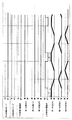
図5には全身噴出モードの動作を示しており、図6は下半身噴出モードの動作を示しており、図7は上半身噴出モードの動作を示している。図5、図6、図7において太線は各流出口13から水が流れている状態を示し、水平な太線は該当する流出口13が全開状態で水が流れ、右下がりの太線は該当する流出口13が次第に弁口12との連通面積が減りながら水が流れ、右上がりの太線は該当する流出口13が次第に弁口12との連通面積が増えながら水が流れている状態を示している。   FIG. 5 shows the operation in the whole body ejection mode, FIG. 6 shows the operation in the lower body ejection mode, and FIG. 7 shows the operation in the upper body ejection mode. 5, 6, and 7, a thick line indicates a state in which water flows from each outlet 13, a horizontal thick line indicates that the corresponding outlet 13 is fully open, and water flows, and a lower right bold line indicates the corresponding flow Water flows while the outlet 13 gradually decreases in communication area with the valve port 12, and a thick line rising to the right indicates a state in which water flows while the corresponding outlet 13 gradually increases in communication area with the valve port 12. .

下半身リンパマッサージモードの運転は、図6に示すように、まず、下半身用のポンプ6aをオンにし、更に下半身用の電動弁7aをオンにする(この場合上半身用のポンプ6b、上半身用の電動弁7aはオフである)と、図6に示すように足先噴出用となる第1の噴出口2a→足首脹脛噴出用となる第2の噴出口2b→膝裏噴出用となる第3の噴出口2cの順に水流が噴出して入浴者Mの身体の足先部分、足首脹脛部分、膝裏部分の順に水流が当たって、これらの各部を順次水流によりマッサージをすると共に、足先側から腰の方に向かって順にリンパ管を揉み上げてリンパ管内のリンパ液をスムーズに流して下半身のリンパマッサージを行うことができる。   As shown in FIG. 6, in the lower body lymphatic massage mode, first, the lower body pump 6a is turned on, and the lower body electric valve 7a is turned on (in this case, the upper body pump 6b and the upper body electric motor). When the valve 7a is off), as shown in FIG. 6, a first jet 2a for foot tip ejection → second jet 2b for ankle calf ejection → third knee jet The water flow squirts in the order of the spout 2c, and the water flows in the order of the toe part of the body of the bather M, the ankle calf part, and the back of the knee part. Lymphatic massage in the lower body can be performed by squeezing up the lymphatic vessels in order toward the waist and smoothly flowing the lymph in the lymphatic vessels.

また、上半身リンパマッサージモードの運転は、図7に示すように、上半身用のポンプ6bをオンにし、更に上半身用の電動弁7bをオンにする(この場合下半身用のポンプ6a、下半身用の電動弁7bはオフである)と、図7に示すように腰・背中噴出用となる第1の噴出口2a→腕付根噴出用となる第2の噴出口2b→肩噴出用となる第3の噴出口2cの順に水流が噴出して入浴者Mの身体の腰・背中部分、腕付根部分、肩部分の順に水流が当たって、これらの各部を順次水流によりマッサージをすると共に、腰側から肩の方に向かって順にリンパ管を揉み上げてリンパ管内のリンパ液をスムーズに流して上半身のリンパマッサージを行うことになる。   In the operation of the upper body lymph massage mode, as shown in FIG. 7, the upper body pump 6b is turned on, and the upper body electric valve 7b is turned on (in this case, the lower body pump 6a and the lower body electric motor). Valve 7b is off), as shown in FIG. 7, the first jet port 2a for the waist and back jets, the second jet port 2b for the armed root jets, and the third jet for the shoulder jets. The water flows in the order of the spout 2c, and the water flows in the order of the waist / back portion of the body of the bather M, the root portion of the arm, and the shoulder portion. Lymphatic massage of the upper body is performed by squeezing the lymphatic vessels in order toward the side and smoothly flowing the lymph in the lymphatic vessels.

更に、全身リンパマッサージモードの運転は、図5に示すように、上記下半身リンパマッサージモードの1サイクルの運転に引き続いて上記上半身リンパマッサージ運転の1サイクルの運転を行い、以降これを繰り返すものである。   Further, as shown in FIG. 5, the operation in the whole body lymph massage mode is performed by performing the one cycle operation of the upper body lymph massage operation following the one cycle operation in the lower body lymph massage mode, and thereafter repeating this. .

上記足先噴出用の第1の噴出口2aから噴出する水流が内くるぶし下に在る添付図面で符号100で示す「照海」というツボに当たるようにすると「照海」というツボマッサージができる。両内くるぶし下に在る「照海」というツボに水流が当たるようにするには、足先配置部14側の側壁部16bの下部の左右方向の中央部に足先噴出用の第1の噴出口2aを配置して平面視で斜め方向に水流を噴出するように構成することで、内くるぶし下に在る「照海」というツボに水流を当てて「照海」のツボマッサージができる。この場合、足先噴出用の第1の噴出口2aを水平視で首振り運動するように構成して両足の内くるぶし下に在る「照海」を順番にツボマッサージするようにしてもよい。もちろん、足先噴出用の第1の噴出口2aから噴出する水流が足裏に当たるようにすると足裏に在るツボのマッサージができる。   Acupuncture massage called “Terumi” can be performed when the water flow ejected from the first jet outlet 2a for foot tip hits the acupuncture point “Terumi” indicated by reference numeral 100 in the attached drawing under the inner ankle. In order to allow the water flow to hit the acupuncture point “Terumi” located under the inner ankles, the first foot-spouting first central portion in the left-right direction below the side wall portion 16b on the foot-tip arrangement portion 14 side is used. By arranging the spout 2a and ejecting the water flow in an oblique direction in plan view, the acupuncture massage of “Terumi” can be performed by applying the water flow to the “Terumi” acupuncture point under the ankle. . In this case, the first jet outlet 2a for foot tip ejection may be configured to swing in a horizontal view so that “Terumi” under the ankles of both feet may be massaged in order. . Of course, if the water flow ejected from the first spout 2a for foot tip ejection hits the sole, massage of the acupuncture points on the sole can be performed.

また、足首脹脛噴出用の第2の噴出口2bから足首脹脛に水流を当てることで足首脹脛に在る添付図面で符号101、102で示す「三陰交」、「承山」というツボのツボマッサージができる。   In addition, by applying water to the ankle calf from the second spout 2b for ejecting the ankle calf, the acupuncture point massages “San Yin Ko” and “Chiyama” indicated by reference numerals 101 and 102 in the attached shin are shown. it can.

更に、膝裏噴出用の第3の噴出口2cから膝裏に水流を当てることで膝裏に在る添付図面で符号103で示す「委中」というツボのツボマッサージができる。   Further, by applying a water flow to the back of the knee from the third jet outlet 2c for jetting the back of the knee, the acupoint massage of the acupuncture point “dedicated” indicated by reference numeral 103 in the attached drawing on the back of the knee can be performed.

同様に、腰・背中噴出用の第1の噴出口2aから水流を噴出することで、腰や背中にあるツボのマッサージができるのであるが、ここで、腰・背中噴出用の第1の噴出口2aを垂直面内で首振り自在とすると、腰・背中に在る添付図面で符号104、105、106、107で示す「腎兪」、「胃兪」、「肝兪」、「心兪」というツボに次々と水流が当たってこれらのツボマッサージをすることができる。   Similarly, acupuncture can be massaged on the waist and back by ejecting a water stream from the first jet outlet 2a for jetting the waist and back. Here, the first jet for jetting the waist and back is used. If the outlet 2a can be swung freely in a vertical plane, “renal fistula”, “gastric fistula”, “hepatic fistula”, “heart fistula” indicated by reference numerals 104, 105, 106, 107 in the attached drawings on the waist and back. You can massage these acupuncture points by hitting the acupuncture points one after another.

また、腕付根用の第2の噴出口2bから腕付根に水流を当てることで腕付根に在る添付図面で符号108で示す「天宗」というツボのツボマッサージができる。   In addition, by applying a water flow from the second spout 2b for the arm root to the arm root, an acupuncture point massage “Tenso” indicated by reference numeral 108 in the attached drawing at the arm root can be performed.

更に、肩噴出用の第3の噴出口2cから肩に水流を当てることで肩に在る添付図面で符号109で示す「肩井」というツボのツボマッサージができる。   Further, by applying a water flow to the shoulder from the third jet outlet 2c for shoulder ejection, an acupuncture point massage “shoulder” indicated by reference numeral 109 in the attached drawing on the shoulder can be performed.

このようにしてリンパマッサージを行いながら同時に順番にツボマッサージを行うことができる。   In this way, the acupoint massage can be performed sequentially while performing the lymphatic massage.

そして、上記いずれのツボマッサージにおいても、図5、図6、図7に示すように回動弁体11の回動により弁口12と複数の流出口との連通状態が変化するようにした電動弁7を用いることで、図5、図6、図7の右上がりの太線で示すように入浴者のマッサージ対象の各ツボに対して水流が最初は弱く、次第に強く、最大の強さとなり、その後、図5、図6、図7の右下がりの太線で示すように次第に弱くなるように当たり、あたかも指でツボをマッサージするのに近いマッサージ感が得られることになる。   In any of the above acupoint massages, as shown in FIGS. 5, 6, and 7, the electric connection state between the valve port 12 and the plurality of outlets is changed by the rotation of the rotary valve body 11. By using the valve 7, the water flow is initially weak, gradually strong, and maximum strength for each acupuncture point of the bather as shown in the thick line rising to the right in FIGS. 5, 6, 7, After that, as shown by the bold lines at the lower right of FIG. 5, FIG. 6, and FIG. 7, it is gradually weakened, and a massage feeling similar to that of massaging acupoints with fingers is obtained.

もちろん、上記以外のツボを狙って噴出口2から水流を噴出して該当箇所のツボをツボマッサージするようにしてもよい。   Of course, you may make it acupoint massage the acupuncture point of a point by spouting a water flow from the jet nozzle 2 aiming at a point other than the above.

また、上記実施形態では下半身用の第1のポンプ6a、上半身用の第2のポンプ6bを設けた例を示したが、1つのポンプ6を用いて上記のようなツボマッサージを順番に行いながらリンパマッサージを行うようにしてもよい。   Moreover, although the example which provided the 1st pump 6a for lower body and the 2nd pump 6b for upper body was shown in the said embodiment, while performing the acupuncture massage as mentioned above using one pump 6 in order. You may make it perform lymphatic massage.

また、図5、図6、図7に示す実施形態では、第1のポンプ6aをオンにして一定時間(t)後に下半身用の電動弁7aをオンしたり、あるいは、第2のポンプ6bをオンにして一定時間(t)後に上半身用の電動弁7bをオンしたりするように制御部4により下半身用の電動弁7aや上半身用の電動弁7bを制御する例を示しているが、図8、図9、図10に示すように第1のポンプ6aのオンと同時に下半身用の電動弁7aをオンするように制御部4により制御すると共に、第2のポンプ6aのオフと同時に下半身用の電動弁7aをオフするように制御部4により制御したり、あるいは、第2のポンプ6bのオンと同時に上半身用の電動弁7bをオンするように制御部4により制御すると共に、第2のポンプ6aのオフと同時に上半身用の電動弁7bをオフするように制御部4により制御したりしてもよい。   In the embodiment shown in FIGS. 5, 6, and 7, the first pump 6a is turned on and the lower half motorized valve 7a is turned on after a predetermined time (t), or the second pump 6b is turned on. An example is shown in which the control unit 4 controls the lower body motor valve 7a and the upper body motor valve 7b so that the upper body motor valve 7b is turned on after a predetermined time (t). As shown in FIGS. 8, 9, and 10, the control unit 4 controls to turn on the motor valve 7a for the lower body at the same time as the first pump 6a is turned on, and for the lower body at the same time as the second pump 6a is turned off. The control unit 4 controls the motor valve 7a to turn off, or the control unit 4 controls to turn on the motor valve 7b for the upper body at the same time as the second pump 6b is turned on. For upper body when pump 6a is off It may or controlled by the control unit 4 so as to turn off the electric valve 7b.

また、上記図1の実施形態は全身のマッサージが行えるようにした例を示したが、図2のように下半身のみのマッサージ(例えば前述と同様の下半身のリンパマッサージ)を行うようにしたものでもよく、あるいは図3のように上半身のみのマッサージ(例えば前述と同様の上半身のリンパマッサージ)を行うようにしたものでもよい。   Further, although the embodiment of FIG. 1 shows an example in which the whole body massage can be performed, the massage of only the lower body as shown in FIG. 2 (for example, the lower body lymphatic massage similar to the above) may be performed. Alternatively, as shown in FIG. 3, massage may be performed only on the upper body (for example, lymph massage on the upper body as described above).

また、上記実施形態では電動弁7に3つの流出口13を設けて3つの噴出口2にそれぞれ連通させた例を示したが、2つ又は4つ以上の流出口13を設けて2つ又は4つ以上の噴出口2に連通させてもよい。更に、電動弁7に1つの流出口13を設けて1つの噴出口2に連通させてもよい。   Moreover, although the example which provided the three outlets 13 in the motor operated valve 7 and made it communicate with each of the three jet nozzles 2 was shown in the said embodiment, two or four or more outlets 13 were provided, and two or You may make it connect with four or more jet nozzles 2. FIG. Furthermore, the motor-operated valve 7 may be provided with one outflow port 13 so as to communicate with one jet port 2.

本発明の一実施形態を示し、(a)は側断面図であり、(b)は平面図である。1 shows an embodiment of the present invention, in which (a) is a side sectional view and (b) is a plan view. 同上の他の実施形態を示し、(a)は側断面図であり、(b)は平面図である。Other embodiment same as the above is shown, (a) is a sectional side view, (b) is a plan view. 同上の更に他の実施形態を示し、(a)は側断面図であり、(b)は平面図である。Another embodiment same as the above is shown, (a) is a side sectional view, and (b) is a plan view. 同上に用いる電動弁の一実施形態を示し、(a)は平面図であり、(b)は回動弁体の断面図である。An embodiment of the motor-operated valve used for the above is shown, (a) is a plan view, and (b) is a cross-sectional view of a rotating valve body. 同上の全身噴出モードの動作状態を示すタイムチャートである。It is a time chart which shows the operation state of a whole body ejection mode same as the above. 同上の下半身噴出モードの動作状態を示すタイムチャートである。It is a time chart which shows the operation state of lower body ejection mode same as the above. 同上の上半身噴出モードの動作状態を示すタイムチャートである。It is a time chart which shows the operation state of upper body ejection mode same as the above. 同上の全身噴出モードの動作状態を示すタイムチャートである。It is a time chart which shows the operation state of a whole body ejection mode same as the above. 同上の下半身噴出モードの動作状態を示すタイムチャートである。It is a time chart which shows the operation state of lower body ejection mode same as the above. 同上の上半身噴出モードの動作状態を示す他の実施形態のタイムチャートである。It is a time chart of other embodiment which shows the operation state of upper body ejection mode same as the above. (a)(b)はそれぞれ噴出口から噴出する水流の流速の変化を示すグラフである。(A) (b) is a graph which shows the change of the flow velocity of the water flow each ejected from a jet nozzle.

1 浴槽
2 噴出口
3 流速可変手段
6 ポンプ
7 電動弁
8 弁本体
9 孔
10 モータ
11 回動弁体
12 弁口
13 流出口
M 入浴者
DESCRIPTION OF SYMBOLS 1 Bathtub 2 Outlet 3 Flow rate variable means 6 Pump 7 Electric valve 8 Valve body 9 Hole 10 Motor 11 Rotating valve body 12 Valve port 13 Outlet M Bathing person

Claims (4)

浴槽内の浴水中に入浴している入浴者の下半身に浴水の水流によりマッサージするための水流噴出装置付浴槽であって、浴槽に、入浴者の下半身における心臓からの距離が異なる複数個所に浴槽内の浴水を水流として間欠的に噴出するための複数の噴出口を設け、上記複数の噴出口からの噴射が、心臓から遠い方に位置する噴出口から心臓に近い方の噴出口にかけて順番に水流を間欠的に噴射し、且つ、各噴出口からの水流の間欠的な噴出の際に該間欠噴出区間の始めにゆっくりと噴出を開始して次第に流速を速く且つ間欠噴出区間の終りに次第に流速が遅くなってゆっくりと噴出が止まるようにするための流速可変手段を設け、該流速可変手段を、ポンプと噴出口との間に設けた電動弁により構成し、該電動弁を、弁本体に設けた孔に嵌め込まれたモータにより回動する回動弁体と、回動弁体に設けた水の供給用の弁口と、孔の壁面における弁口の回転軌跡の複数個所に対応する位置に隔設して設けた複数の流出口とで構成し、回動弁体の回動により弁口が複数の流出口と順番に連通し、且つ、弁口の各流出口とが連通する際回動弁体の回動により連通状態が変化するものであることを特徴とする水流噴出装置付浴槽 A bathtub with a water jet device that massages the lower body of a bather bathing in the bath water with the water flow of the bath water. A plurality of spouts for intermittently spouting bath water in the bathtub as a water flow are provided, and the spray from the plurality of spouts is directed from a spout located far from the heart to a spout near the heart. The water flow is intermittently ejected in order, and when the water flow is intermittently ejected from each ejection port, the ejection is slowly started at the beginning of the intermittent ejection section, and the flow rate is gradually increased and the end of the intermittent ejection section. The flow rate variable means for gradually stopping the jet flow slowly and stopping the ejection is provided, the flow rate variable means is constituted by a motorized valve provided between the pump and the jet outlet, the motorized valve, Fits into the hole in the valve body A rotating valve body that is rotated by a rare motor, a water supply valve port provided on the rotating valve body, and a position corresponding to a plurality of positions of a rotation trajectory of the valve port on the wall surface of the hole. A plurality of outlets provided, and when the rotary valve body rotates, the valve port communicates with the plurality of outlets in order, and when the rotary valve body communicates with each outlet port of the valve port, A bathtub with a water jet device, wherein the communication state is changed by rotation. 水流を噴出する間欠噴出区間の始めにゆっくりと噴出を開始して次第に流速が速くなり、最大流速に達した時点をピークとして次第に流速が遅くなってゆっくりと噴出が止まることを特徴とする請求項1記載の水流噴出装置付浴槽The flow rate gradually increases at the beginning of the intermittent ejection section for ejecting the water flow, and then the flow rate gradually increases.The peak is reached when the maximum flow rate is reached, and then the flow rate gradually decreases and the ejection stops slowly. The bathtub with a water jet apparatus according to 1. 水流を噴出する間欠噴出区間の始めにゆっくりと噴出を開始して次第に流速が速くなり、最大流速に達すると該最大流速を一定時間継続し、最大流速を一定時間継続した後に次第に流速が遅くなってゆっくりと噴出が止まることを特徴とする請求項1記載の水流噴出装置付浴槽Slow ejection starts at the beginning of the intermittent ejection section that ejects water flow, and the flow velocity gradually increases.When the maximum flow velocity is reached, the maximum flow velocity continues for a certain period of time, and after the maximum flow velocity continues for a certain period of time, the flow velocity gradually decreases. 2. The bathtub with a water jet device according to claim 1, wherein the jet stops slowly. 入浴者の身体の異なる部位にそれぞれ水流を間欠的に噴出するための複数の噴出口を浴槽に設け、上記弁本体の孔の壁面における弁口の回動軌跡の複数箇所に対応する位置に複数の流出口を隔設し、弁口の周方向の長さを周方向に隣接する流出口間の周方向の長さよりも長くして成ることを特徴とする請求項1乃至請求項3のいずれか一項に記載の水流噴出装置付浴槽The bathtub is provided with a plurality of spouts for intermittently ejecting water flows to different parts of the bather's body, and a plurality of positions are provided at positions corresponding to the plurality of positions of the valve port on the wall surface of the valve body hole. 4. The flow outlet according to claim 1, wherein a circumferential length of the valve port is longer than a circumferential length between the circumferentially adjacent outlets. 5. A bathtub with a water jet device according to claim 1.
JP2005154691A 2005-05-26 2005-05-26 Bathtub with water jet Expired - Fee Related JP4613697B2 (en)

Priority Applications (1)

Application Number Priority Date Filing Date Title
JP2005154691A JP4613697B2 (en) 2005-05-26 2005-05-26 Bathtub with water jet

Applications Claiming Priority (1)

Application Number Priority Date Filing Date Title
JP2005154691A JP4613697B2 (en) 2005-05-26 2005-05-26 Bathtub with water jet

Publications (2)

Publication Number Publication Date
JP2006325993A JP2006325993A (en) 2006-12-07
JP4613697B2 true JP4613697B2 (en) 2011-01-19

Family

ID=37548329

Family Applications (1)

Application Number Title Priority Date Filing Date
JP2005154691A Expired - Fee Related JP4613697B2 (en) 2005-05-26 2005-05-26 Bathtub with water jet

Country Status (1)

Country Link
JP (1) JP4613697B2 (en)

Families Citing this family (2)

* Cited by examiner, † Cited by third party
Publication number Priority date Publication date Assignee Title
DE102012020109A1 (en) 2012-10-12 2014-04-17 Nidec Motors & Aktuators (Germany) Gmbh Electric machine, in particular permanent magnet motor and method for providing the electrical windings thereof
JP7617616B2 (en) 2019-11-29 2025-01-20 株式会社三彩 Bathtub

Family Cites Families (7)

* Cited by examiner, † Cited by third party
Publication number Priority date Publication date Assignee Title
IT1200742B (en) * 1985-09-17 1989-01-27 Teuco Guzzini Srl BATHTUB WITH PERFECTED HYDROMASSAGE SYSTEM
JPH0612772Y2 (en) * 1989-02-01 1994-04-06 株式会社イナックス Bubble bath equipment
JPH02274251A (en) * 1989-04-17 1990-11-08 Matsushita Electric Ind Co Ltd Jet blowing device
FR2674125B1 (en) * 1991-03-20 1998-11-06 Robert Antoine MASSAGE SHOWER SYSTEM AND MASSAGE SHOWER CABIN OF SUCH A SYSTEM.
JP2598204Y2 (en) * 1992-09-18 1999-08-03 株式会社アルファ・コーポレーション Jet control device for whirlpool
JP3192334B2 (en) * 1994-11-15 2001-07-23 松下電工株式会社 Bathtub jet flow switching structure
JP3151362B2 (en) * 1994-11-25 2001-04-03 松下電工株式会社 Air flow control device for bubble generating bathtub

Also Published As

Publication number Publication date
JP2006325993A (en) 2006-12-07

Similar Documents

Publication Publication Date Title
JP4715292B2 (en) Bathtub equipment
CN106821721A (en) A kind of stream impulse masseur for acupoint of foot bottom
JP4613697B2 (en) Bathtub with water jet
KR20090099249A (en) Comb shower head
JP4482498B2 (en) Water jetting device
JP4479588B2 (en) Water jetting device
JP4613561B2 (en) Bathtub equipment
CN207545455U (en) A kind of stream impulse masseur for acupoint of foot bottom
JP2007159666A (en) Stream jetting apparatus
JP2007209474A (en) Bathtub apparatus
KR101472803B1 (en) Shower head with massage function
JP4752592B2 (en) Bathtub
US20230414447A1 (en) Liquid Tongue
JP3133808B2 (en) Circulating tub sprayer
JP2007260266A (en) Bathing bath
JP4844375B2 (en) Bathtub equipment
JPH0410821Y2 (en)
JP4062295B2 (en) Lymphatic massage bath
JP2005318950A (en) Bathtub device
JP4774969B2 (en) Water jetting device
JPH0733787Y2 (en) Bubble generating bath
JPH0215477Y2 (en)
JP2007209562A (en) Bathtub apparatus
JP2007209493A (en) Nozzle for bathtub and bathtub apparatus
JP2007209563A (en) Bathtub apparatus

Legal Events

Date Code Title Description
A621 Written request for application examination

Free format text: JAPANESE INTERMEDIATE CODE: A621

Effective date: 20070921

A131 Notification of reasons for refusal

Free format text: JAPANESE INTERMEDIATE CODE: A131

Effective date: 20090714

A521 Request for written amendment filed

Free format text: JAPANESE INTERMEDIATE CODE: A523

Effective date: 20090914

A02 Decision of refusal

Free format text: JAPANESE INTERMEDIATE CODE: A02

Effective date: 20100223

A521 Request for written amendment filed

Free format text: JAPANESE INTERMEDIATE CODE: A523

Effective date: 20100524

A911 Transfer to examiner for re-examination before appeal (zenchi)

Free format text: JAPANESE INTERMEDIATE CODE: A911

Effective date: 20100602

RD04 Notification of resignation of power of attorney

Free format text: JAPANESE INTERMEDIATE CODE: A7424

Effective date: 20100708

TRDD Decision of grant or rejection written
A01 Written decision to grant a patent or to grant a registration (utility model)

Free format text: JAPANESE INTERMEDIATE CODE: A01

Effective date: 20100921

A01 Written decision to grant a patent or to grant a registration (utility model)

Free format text: JAPANESE INTERMEDIATE CODE: A01

A61 First payment of annual fees (during grant procedure)

Free format text: JAPANESE INTERMEDIATE CODE: A61

Effective date: 20101004

R151 Written notification of patent or utility model registration

Ref document number: 4613697

Country of ref document: JP

Free format text: JAPANESE INTERMEDIATE CODE: R151

FPAY Renewal fee payment (event date is renewal date of database)

Free format text: PAYMENT UNTIL: 20131029

Year of fee payment: 3

LAPS Cancellation because of no payment of annual fees