JP4596748B2 - Radiographic imaging apparatus and reconstruction method in radiographic imaging apparatus - Google Patents
Radiographic imaging apparatus and reconstruction method in radiographic imaging apparatus Download PDFInfo
- Publication number
- JP4596748B2 JP4596748B2 JP2003129453A JP2003129453A JP4596748B2 JP 4596748 B2 JP4596748 B2 JP 4596748B2 JP 2003129453 A JP2003129453 A JP 2003129453A JP 2003129453 A JP2003129453 A JP 2003129453A JP 4596748 B2 JP4596748 B2 JP 4596748B2
- Authority
- JP
- Japan
- Prior art keywords
- grid
- image data
- image
- gain
- radiation
- Prior art date
- Legal status (The legal status is an assumption and is not a legal conclusion. Google has not performed a legal analysis and makes no representation as to the accuracy of the status listed.)
- Expired - Fee Related
Links
- 238000000034 method Methods 0.000 title claims description 32
- 238000003384 imaging method Methods 0.000 title claims description 24
- 230000005855 radiation Effects 0.000 claims description 47
- 230000008569 process Effects 0.000 claims description 14
- 238000001514 detection method Methods 0.000 description 9
- 230000006870 function Effects 0.000 description 9
- 238000001228 spectrum Methods 0.000 description 9
- 238000010586 diagram Methods 0.000 description 8
- 238000006243 chemical reaction Methods 0.000 description 5
- 238000013480 data collection Methods 0.000 description 4
- 230000007246 mechanism Effects 0.000 description 4
- 238000005070 sampling Methods 0.000 description 4
- 230000008901 benefit Effects 0.000 description 2
- 238000013170 computed tomography imaging Methods 0.000 description 2
- 238000002438 flame photometric detection Methods 0.000 description 2
- 239000006096 absorbing agent Substances 0.000 description 1
- 239000011358 absorbing material Substances 0.000 description 1
- 230000002238 attenuated effect Effects 0.000 description 1
- 238000004364 calculation method Methods 0.000 description 1
- 230000008859 change Effects 0.000 description 1
- 230000000694 effects Effects 0.000 description 1
- 238000001914 filtration Methods 0.000 description 1
- 239000011521 glass Substances 0.000 description 1
- 239000000463 material Substances 0.000 description 1
- 230000003287 optical effect Effects 0.000 description 1
- 238000000926 separation method Methods 0.000 description 1
- 239000000758 substrate Substances 0.000 description 1
- 238000003325 tomography Methods 0.000 description 1
- WFKWXMTUELFFGS-UHFFFAOYSA-N tungsten Chemical compound [W] WFKWXMTUELFFGS-UHFFFAOYSA-N 0.000 description 1
- 229910052721 tungsten Inorganic materials 0.000 description 1
- 239000010937 tungsten Substances 0.000 description 1
Images


Classifications
-
- A—HUMAN NECESSITIES
- A61—MEDICAL OR VETERINARY SCIENCE; HYGIENE
- A61B—DIAGNOSIS; SURGERY; IDENTIFICATION
- A61B6/00—Apparatus or devices for radiation diagnosis; Apparatus or devices for radiation diagnosis combined with radiation therapy equipment
- A61B6/58—Testing, adjusting or calibrating thereof
- A61B6/582—Calibration
- A61B6/583—Calibration using calibration phantoms
-
- A—HUMAN NECESSITIES
- A61—MEDICAL OR VETERINARY SCIENCE; HYGIENE
- A61B—DIAGNOSIS; SURGERY; IDENTIFICATION
- A61B6/00—Apparatus or devices for radiation diagnosis; Apparatus or devices for radiation diagnosis combined with radiation therapy equipment
- A61B6/02—Arrangements for diagnosis sequentially in different planes; Stereoscopic radiation diagnosis
- A61B6/03—Computed tomography [CT]
- A61B6/032—Transmission computed tomography [CT]
-
- A—HUMAN NECESSITIES
- A61—MEDICAL OR VETERINARY SCIENCE; HYGIENE
- A61B—DIAGNOSIS; SURGERY; IDENTIFICATION
- A61B6/00—Apparatus or devices for radiation diagnosis; Apparatus or devices for radiation diagnosis combined with radiation therapy equipment
- A61B6/06—Diaphragms
-
- A—HUMAN NECESSITIES
- A61—MEDICAL OR VETERINARY SCIENCE; HYGIENE
- A61B—DIAGNOSIS; SURGERY; IDENTIFICATION
- A61B6/00—Apparatus or devices for radiation diagnosis; Apparatus or devices for radiation diagnosis combined with radiation therapy equipment
- A61B6/40—Arrangements for generating radiation specially adapted for radiation diagnosis
- A61B6/4064—Arrangements for generating radiation specially adapted for radiation diagnosis specially adapted for producing a particular type of beam
- A61B6/4085—Cone-beams
-
- A—HUMAN NECESSITIES
- A61—MEDICAL OR VETERINARY SCIENCE; HYGIENE
- A61B—DIAGNOSIS; SURGERY; IDENTIFICATION
- A61B6/00—Apparatus or devices for radiation diagnosis; Apparatus or devices for radiation diagnosis combined with radiation therapy equipment
- A61B6/42—Arrangements for detecting radiation specially adapted for radiation diagnosis
- A61B6/4291—Arrangements for detecting radiation specially adapted for radiation diagnosis the detector being combined with a grid or grating
-
- A—HUMAN NECESSITIES
- A61—MEDICAL OR VETERINARY SCIENCE; HYGIENE
- A61B—DIAGNOSIS; SURGERY; IDENTIFICATION
- A61B6/00—Apparatus or devices for radiation diagnosis; Apparatus or devices for radiation diagnosis combined with radiation therapy equipment
- A61B6/52—Devices using data or image processing specially adapted for radiation diagnosis
- A61B6/5211—Devices using data or image processing specially adapted for radiation diagnosis involving processing of medical diagnostic data
- A61B6/5252—Devices using data or image processing specially adapted for radiation diagnosis involving processing of medical diagnostic data removing objects from field of view, e.g. removing patient table from a CT image
-
- G—PHYSICS
- G21—NUCLEAR PHYSICS; NUCLEAR ENGINEERING
- G21K—TECHNIQUES FOR HANDLING PARTICLES OR IONISING RADIATION NOT OTHERWISE PROVIDED FOR; IRRADIATION DEVICES; GAMMA RAY OR X-RAY MICROSCOPES
- G21K1/00—Arrangements for handling particles or ionising radiation, e.g. focusing or moderating
- G21K1/10—Scattering devices; Absorbing devices; Ionising radiation filters
Landscapes
- Health & Medical Sciences (AREA)
- Life Sciences & Earth Sciences (AREA)
- Engineering & Computer Science (AREA)
- Medical Informatics (AREA)
- Physics & Mathematics (AREA)
- High Energy & Nuclear Physics (AREA)
- Radiology & Medical Imaging (AREA)
- Molecular Biology (AREA)
- Veterinary Medicine (AREA)
- Nuclear Medicine, Radiotherapy & Molecular Imaging (AREA)
- Optics & Photonics (AREA)
- Pathology (AREA)
- Public Health (AREA)
- Biomedical Technology (AREA)
- Heart & Thoracic Surgery (AREA)
- Biophysics (AREA)
- Surgery (AREA)
- Animal Behavior & Ethology (AREA)
- General Health & Medical Sciences (AREA)
- Spectroscopy & Molecular Physics (AREA)
- General Engineering & Computer Science (AREA)
- Pulmonology (AREA)
- Theoretical Computer Science (AREA)
- Computer Vision & Pattern Recognition (AREA)
- Apparatus For Radiation Diagnosis (AREA)
Description
【0001】
【発明の属する技術分野】
本発明は、例えばX線等の放射線を利用してCT(computerized tomography)撮影を行う放射線撮像装置に関する。
【0002】
【従来の技術】
従来、被検体に対してX線を曝射し、該被検体を透過した、或いは被検体で散乱したX線をX線検出器で検出し、このX線検出出力(X線のフォトン数)に基づいて被検体の透視画像、断層像或いは三次元画像を提供するX線CT装置が知られている。
【0003】
かかるX線CT装置として、近年、コーンビームCT装置が開発されている。通常のX線CT装置では、Z方向に薄く切り出されたX線ビーム(これをファンビームと称する)が用いられる。これに対して、コーンビームCT装置では、Z方向にも広がったX線ビーム(このX線ビームはコーンビームと呼ばれる)が用いられる。
【0004】
そして、このコーンビームCT装置としては、現在のところ、従来型CT装置(すなわちrowが1列だけのもの)において、いわゆる第3世代型あるいはR/R型と呼ばれる方式に相当する形式において実現することが検討されている。この第3世代型CTとは、X線源と検出器のペアが被検体の周囲を回動しながらスキャン(投影データの収集)を行うものである。
【0005】
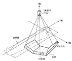
図2は、コーンビームCT装置の一例を示す図である。図2に示すコーンビームCT装置は、第3世代型CT装置に属するものであり、Z軸を回転軸として、X線源とともにX線検出器も被検体の周囲を回動し、一回転で関心領域のスキャンを終える。通常のX線CT装置では、チャンネル(CH)方向にサンプリングするために検出素子がCH方向に1ライン並んでおり、個々の素子はチャンネル番号で識別される。これに対し、コーンビームCT装置では、図2に示すように、検出素子がさらにZ方向(row方向)にも配列されている。すなわち、コーンビームCT装置における検出器は、検出素子が直交格子状に2次元配置されて構成される。このようなコーンビームCT装置によれば、検出素子をz方向(row方向)及びCH方向の2方向に格子状に配置して検出器を構成するとともに、放射線をZ方向にも厚みをもたせた円錐(コーン)状に曝射することによって、複数列分の投影データを一括して得ることができる。
【0006】
以上のようなコーンビームCT装置においては、フラットパネルディテクタ(FPD)を使用した装置の製品化が期待されている。しかしながら、従来の一次元状のセンサと異なり、2次元センサであるFPDでは散乱線の混入が大きくなり、コントラストを低下させる問題が予想される。
【0007】
コーンビームCT装置においては、散乱線除去のためにCH方向には、検出素子間を分離するように鉛やタングステン製の分離板を挿入し、Z軸方向で分離するためにブレード(スリット)を挿入している。一方、FPDを使用したX線撮影においては、特許文献4に記載されているように、散乱線除去用のグリッドが一般に使用される。ブレードはZ軸方向の検出器を分離するために検出器の間に挿入されるものであり、つまりZ方向の検出器ピッチとブレードピッチは同一となる。反面、グリッドは検出器の前面に配置されるので、検出器を遮蔽する配置となる場合があり、これにより画像に影が発生する。
【0008】
特許文献1には、Z軸方向に挿入する散乱線除去用のブレードがZ軸方向の分離のための検出素子毎に複数枚挿入される技術が開示されている。ここでは、これらZ方向に複数枚設けられたブレードモジュールが、第四世代CT(CH方向に、検出器が環状をなすCT装置)の検出器上を移動する技術も開示されている。
【0009】
特許文献2には、コーンビームCT装置において、散乱線を除去するためにX線撮影で使用されるようなグリッドを使用することが開示されている。特許文献2では、グリッドを挿入することにより発生する収集データ中のモアレを回避するために、撮影中にグリッド像が残らないようにグリッド要素の延びる方向と交差する方向に移動させる。
【0010】
特許文献3には、FPDのガラス基盤に格子状の溝を設けて、その溝にX線吸収材料を充填封入して散乱線を減少させる構造が記載されている。
【0011】
特許文献4には、X線撮影において、固定されたグリッドを用いて撮影した場合の画像中から、データ処理によってグリッド縞を低減させる技術が開示されている。
【0012】
【特許文献1】
特開2000−107162号公報
【特許文献2】
特開2000−157530号公報
【特許文献3】
特開2001−188096号公報
【特許文献4】
特開2001−212139号公報
【0013】
【発明が解決しようとする課題】
さて、コーンビームCT装置を構成しようとする場合に、Z軸方向にブレード入れることが特許文献1に開示されている。しかしながら、FPDを使用したコーンビームCT装置では、特許文献1に記載されているようにZ軸方向に検出器毎にブレード入れることは機構上困難であり、仮にできたとしても高価な構造となる。なぜなら、FPDを用いた場合、Z軸方向にも数百チャンネル(CH)の検出素子を並べることが考えられるからである。
【0014】
そこで、特許文献2に提案されているように、CT装置に散乱線除去用のグリッドを適用することが考えられる。しかし、グリッドの欠点は、散乱X線をカットする一方、直接X線の一部も遮断してしまい、その遮断の形態はグリッドの配置に従い、通常縞状の損傷を画像に残すことになる。CTにおいては、回転状に逆投影することから、撮影画像にグリッド縞が残ると、画像再構成の際にリング状偽像(アーティファクト)が発生する。そこで、特許文献2では、グリッド移動機構を設け、撮影中にグリッドを移動することによりグリッドの影を撮影画像から除去する。しかし、円弧状にグリッドを移動させる機構は非常に特殊なものとなる。また、Z軸方向にグリッドを移動させる場合には、回転運動の方向と直交する方向へグリッドを移動することになるために共振などの問題が生じ、現実的ではない。
【0015】
また、特許文献3では散乱X線を除去するべく格子状にX線吸収材を設けた2次元放射線検出器が開示されているが、FPDとグリッドを用いた構成については記載が無い。また、特許文献4には、FPDとグリッドを用いた単純撮影用のX線撮影装置が開示されているが、CT装置については記載がない。
【0016】
本発明は上記の課題に鑑みてなされたものであり、放射線検出器に対して固定されたグリッドを用いて散乱線を除去する構成を備え、CT撮影におけるアーティファクトの発生を効果的に抑制することを目的とする。
【0017】
【課題を解決するための手段】
上記の目的を達成するための本発明による放射線撮像装置は以下の構成を備える。すなわち、
放射線画像撮影装置であって、
放射線源からの放射線を画像データに変換するための複数のフラットパネルディテクタで構成された2次元検出器と、
前記放射線に対して被写体を相対的に回転させる回転手段と、
各フラットパネルディテクタの平面に対応した複数のグリッドによって構成され、前記放射線の散乱線を除去するために前記2次元検出器の前面に、前記放射線源の回転面に平行に配置されたグリッド部と、
前記グリッド部を介して前記2次元検出器で撮像された被写体画像データと、前記グリッド部を介して前記2次元検出器により被写体なしの状態で撮像されたゲイン画像データとを取得する取得手段と、
前記被写体画像データと前記ゲイン画像データとのそれぞれに対してグリッド縞除去処理を行なう画像処理手段と、
前記グリッド縞除去処理された前記被写体画像データに対して、前記グリッド縞除去処理されたゲイン画像データに基づいてゲイン補正する補正手段と、
前記ゲイン補正された被写体画像データを基に画像の再構成を行なう再構成手段とを備える。
【0018】
また、上記の目的を達成するための本発明による放射線撮像装置の制御方法は、
被写体の周囲を回転し且つ前記被写体に放射線を曝射する放射線源と、前記放射線源からの放射線を画像データに変換するための複数のフラットパネルディテクタで構成された2次元検出器と、前記放射線に対して被写体を相対的に回転させる回転手段と、各フラットパネルディテクタの平面に対応した複数のグリッドによって構成され、前記放射線の散乱線を除去するために前記2次元検出器の前面に、前記放射線源の回転面に平行に配置されたグリッド部とを備えた放射線画像撮影装置における再構成方法であって、
前記グリッド部を介して前記2次元検出器で撮像された被写体画像データと、前記グリッド部を介して前記2次元検出器により被写体なしの状態で撮像されたゲイン画像データとを取得する取得工程と、
前記被写体画像データと前記ゲイン画像データとのそれぞれに対してグリッド縞除去処理を行なう画像処理工程と、
前記グリッド縞除去処理された前記被写体画像データに対して、前記グリッド縞除去処理されたゲイン画像データに基づいてゲイン補正する補正工程と、
前記ゲイン補正された被写体画像データを基に画像の再構成を行なう再構成工程とを有する。
【0019】
【発明の実施の形態】
以下、添付の図面を参照して本発明の好ましい実施形態を詳細に説明する。
【0020】
<第1実施形態>
図1は、本発明によるX線CT装置本体の構成例を示す図である。回転フレーム104中にX線管球103が固定され、X線管球103の管球焦点を中心としてX線センサ101が配置される。図1では、X線センサ101は4個の2次元検出器(FPD)から構成され、概略円弧を構成するように配置されている。但し、X線センサ101をさらに細かく分解して(たとえば、16分割)して円弧に配置してもよいし、逆に全部をフラットに配置してもよい。
【0021】
X線センサ101の前面(X線管球側)には散乱線除去のためのグリッド102が配置されている。グリッド102は、再構成領域106に配置された被写体からの散乱線を削減する。グリッド102は、X線単純撮影に使用されるストライプ状のグリッドでも、ストライプを略直交するように重ねた格子グリッドでもよい。以上の構成はガントリ100に納められている。
【0022】
また、グリッド102は、フォーカスタイプでも、平行タイプでのいずれでもよい。フォーカスタイプとはグリッド102の各グリッド要素がフォーカス位置に向けて傾斜して設けられたものであり、平行タイプとは各グリッド要素が互いに平行に設けられたものである。なお、フォーカスタイプのグリッドの方がシェーディングが少なく好ましい。また、フォーカスタイプの場合のフォーカスは当然にX線焦点である。
【0023】
回転フレーム104は、回転用歯車105により再構成領域106の中心を中心として回転する。側面図に示されるように、X線センサ101が回転軸方向にフラットに配置されている。また、この側面図にはこの撮影系による再構成領域106のZ軸方向の大きさが示されている。
【0024】
図2は、本X線CT装置におけるデータ収集系の座標軸を表す図である。この例では、X線センサ101は3つのフラットな2次元検出器(FPD)により構成されており、回転軸をZ軸、チャンネル(CH)方向をX軸、X線焦点位置からX線センサ101の中央に下ろした線をY軸としている。
【0025】
図3は第1実施形態によるX線CT装置のシステム構成図である。X線発生部309の制御によってX線管球103から曝射されたX線は、被写体を透過し、散乱線除去のためのグリッド102によって散乱線が減衰されて、X線センサ101に到達する。なお、グリッド102の挿入方法は、画像再構成の際にリング等のアーティファクトが生じないようにするために、検出素子列に平行に(CH方向に平行、すなわちZ軸を中心とした回転面に平行に)挿入することが望ましい。グリッド縞除去部により完全に縞が除去できなかった場合のリングアーティファクトを考慮するためである。反面、この場合はスライス方向グリッドによるモアレ(ビート)が発生する可能性がある。また、格子状のグリッドを用いる場合にも、各グリッドは検出素子の並びと平行であることが好ましい。
【0026】
X線センサ101からのデータは、AD変換された後に、不図示のデータ収集ユニットに取り込まれる。X線センサ101を構成するFPDは、シンチレータ及び光電変換素子の2次元配列で構成される。なお、光電変換素子及び増幅器系は、オフセットを有するため、オフセット補正部310によりオフセット成分が除去される。オフセット補正には、例えばX線を照射しない状態で得られるX線センサ101からの出力信号に基づいて生成された補正データが用いられる。オフセット補正部310によってオフセット補正された画像は、画像保存部305に保存される。
【0027】
以下、画像保存部305に保存された画像に対して画像処理を施し、グリッド102による影響を排除して画像を再構成する処理について説明する。以下では、第1実施形態の処理手順を示す図4のフローチャートを参照して説明する。
【0028】
X線センサ101によって撮影された画像は基本的には2種類ある。ひとつはゲイン補正をするためのゲイン画像であり、他方は、検査対象の被写体を撮影した画像である。ゲイン画像は、再構成領域106になにも置かずに、あるいは均質の材料を置いて収集された画像であり、画像保存部305に保存される(ステップS101)。なお、一般にはゲイン画像は、被写体画像の撮影前に撮影されるが、被写体画像の撮影のあとに撮影してもよい。つまり、再構成された画像のSN比を判断して、SN比が所定の基準より低い場合には、ゲイン画像を取り直して補正をやり直すことも考えられる。
【0029】
次に、再構成領域106に被写体を挿入して撮影を行なって被写体画像を得る(ステップS102)。この被写体画像も画像保存部305に保存される。上記保存された被写体画像とゲイン画像には、それぞれグリッド影が写し込まれているので、割算部306により割算を行ってゲイン補正を行うと同時に、グリッド影をキャンセルする(ステップS103)。これは、ゲイン画像を被写体画像に作用させてゲイン補正を施すものであり、画像をLOG変換して引き算するようにしてもよい。
【0030】
割算後に残存するグリッド影を小さくするには、ゲイン画像と被写体画像のX線撮影条件(主には管電圧)を揃えることが望ましい。つまり、X線条件により複数のゲイン画像を用意しておき、撮影条件に近い状態で得られたゲイン画像を使用するように構成することが好ましい。
【0031】
しかしながら、経験的に、上記割算によって完全にグリッド影を除去することは困難であり、結果として、リング状のアーティファクトが発生してしまう。従って、残存するグリッド影を除去するためにグリッド縞除去部304による縞除去処理が実行される(ステップS104)。グリッド除去のアルゴリズムは、フィルタによる方法とグリッド縞を予測して減算する方法が挙げられる。
【0032】
フィルタによる方法は、グリッド縞の空間周波数がわかっていることにより、その周波数のスペクトルを低減させるフィルタ適用することで行われる。これを図7を用いて説明する。図7の(a)は画像のグリッド縞に直交する方向の1次元の振幅スペクトルの様子を模式的に示している。図7の(a)において、32は画像成分のスペクトル、31はグリッド縞成分のスペクトルであり、ノイズを無視した実質的なスペクトル形状を示している。図7の(b)はグリッド除去フィルタリングを行った後のスペクトルの様子を模式的に示したものである。ここで、33は適用されたフィルタの特性、34はフィルタ通過後の画像スペクトルを表している。
【0033】
一方、グリッド縞を予測して減算する方法は、縞と直行する方向で画像を適当な画素数でスキャンして、その区間内での縞の周波数を検出して、検出された縞と同じ周波数、同じ振幅の縞をサイン波形で作成して、画像から減算する方法である(なお、グリッド縞を予測アルゴリズムは、特開2002−325765号公報の図18、図19に関する説明を参照のこと)。
【0034】
なお、フィルタによる方法、グリッド縞を予測して減算する方法のいずれを適用するにおいても、サンプリングによって生じるビート(振幅変動)の発生の少ない、安定した正弦波状の縞として観察されることが望ましい。特許文献4によれば、このようなビート成分を観測されにくくする条件として、グリッドの空間周波数fgとサンプリング周波数fsの関係をfg≦0.4×fsとすることが記載されている。また、特許文献4によれば、一般的にサンプリング周波数fsは、被写体画像の最高周波数がサンプリング周波数の30%以下となるように設定され、被写体画像への影響を及ぼさないようにグリッド周波数fgは被写体画像の最高周波数よりも高く設定される(fg≧0.3×fs)。よって、本実施形態においても、グリッド周波数fgは、fs(n+0.3)〜fs(n+0.4)もしくはfs(n+0.6)〜fs(n+0.8)[cyc/mm]とするのが好ましい(ただし、nは自然数)。
【0035】
このようにして、グリッド縞除去およびゲイン補正された画像は、再構成部307に転送されて、断層画像或いは3次元画像の再構成が行われる(ステップS105)。再構成された画像は、画像表示部308により表示される(ステップS106)。なお、画像の出力形態は表示器への出力に限られるものではなく、フィルム上への印刷出力等であってもかまわない。
【0036】
以上説明したデータ収集から画像出力までの一連のフローは、システム制御部301により管理、実行される。なお、データ収集の際の機構的な回転等は、機構制御部302により制御される。また、撮影の開始等、操作者からの指示は、ユーザインタフェース部303を介して入力される。
【0037】
以上説明したように、第1実施形態によれば、FPDを用いたコーンビームCT装置において、グリッドによって効果的に散乱線を除去するとともに、グリッドによる画像の損傷を効果的に低減でき、高画質な画像再構成を実現できる。
【0038】
<第2実施形態>
次に第2実施形態について説明する。コーンビームCT装置の構成等は第1実施形態と同様である。
【0039】
図5は、第2実施形態による撮影処理を説明するフローチャートである。ゲイン画像が撮影されると、オフセット補正部310によるオフセット処理の後に、当該ゲイン画像についてステップS104で説明したグリッド縞除去処理が行われる(ステップS201、S202)。こうして、グリッド縞除去されたゲイン画像が、画像保存部305に保存される。
【0040】
次に、被写体画像が取得され、オフセット補正部310によって当該画像のオフセットが補正される(ステップS203)。そして、割算部306にて、被写体画像はグリッド縞の除去されたゲイン画像による割算(LOG変換後は引き算)が適用され、ゲイン補正が行われる(ステップS204)。このゲイン補正された被写体画像には、グリッド縞が残っているので、第1実施形態のステップS104と同様のグリッド縞除去処理が行われる(ステップS205)。
【0041】
以上のようにして、グリッド縞除去およびゲイン補正された画像は、再構成部307に転送されて、断層画像或いは3次元画像の再構成が行われる(ステップS206)。再構成された画像は、画像表示部308により表示される(ステップS207)。なお、画像の出力形態は表示器への出力に限られるものではなく、フィルム上への印刷出力等であってもかまわない。
【0042】
第1実施形態のグリッド縞処理のグリッドはゲイン補正により概ねキャンセルがされているので、非常に小さいスペクトルであるの対して、実施形態2のグリッド縞のスペクトルは強いものとなる。従って、縞検出の閾値を変える必要がある。また、第2実施形態ではグリッド縞の除去されたゲイン画像で割算し、その結果から更にグリッド縞を除去するが、この手順を用いた場合の利点としては以下のことが挙げられる。グリッド縞の除去されたゲイン画像で割算しても完全にグリッド縞が除去されない場合があり、縞が残っていると画像再構成をした際にリングアーティファクトが発生する。そこで、ゲイン補正後に更にグリッド除去を行うと残存縞が除去できるメリットがある。
【0043】
<第3実施形態>
次に第3実施形態について説明する。コーンビームCT装置の構成等は第1実施形態と同様である。
【0044】
図6は、第3実施形態による撮影処理を説明するフローチャートである。第3実施形態では、撮影されたゲイン画像と被写体画像のそれぞれに予めグリッド縞除去処理を適用し、グリッド縞を削除(あるいは低減)しておいて、そのらの画像を割算することによりゲイン補正及びグリッド縞除去を実現するものである。
【0045】
図6において、ゲイン画像が撮影されると、オフセット補正部310によるオフセット処理の後に、当該ゲイン画像についてステップS104で説明したグリッド縞除去処理が行われる(ステップS301、S302)。こうして、グリッド縞除去されたゲイン画像が、画像保存部305に保存される。
【0046】
次に、被写体画像が取得されると、オフセット補正部310によって当該画像のオフセットが補正された後、当該ゲイン画像についてステップS104で説明したグリッド縞除去処理が行われる(ステップS303、S304)。こうして、グリッド縞除去された被写体画像が、画像保存部305に保存される。
【0047】
そして、割算部306にて、グリッド縞の除去された被写体画像にグリッド縞の除去されたゲイン画像による割算(LOG変換後は引き算)が適用され、ゲイン補正が行われる(ステップS305)。
【0048】
以上のようにして、グリッド縞除去およびゲイン補正された画像は、再構成部307に転送されて、断層画像或いは3次元画像の再構成が行われる(ステップS306)。再構成された画像は、画像表示部308により表示される(ステップS307)。なお、画像の出力形態は表示器への出力に限られるものではなく、フィルム上への印刷出力等であってもかまわない。
以上のように、第3実施形態によれば、グリッド縞の除去をゲイン画像と取得画像のそれぞれに施してからゲイン補正をする。この手順を用いた場合、グリッド除去処理を複数回行うことで、再構成画像作成までの計算時間が長くなるが、第2実施形態と同様に縞の残存がある場合に有利である。
【0049】
以上説明したように上記各実施形態によれば、FPDを使用したコーンビームCT装置において、グリッドを用いて散乱線の除去が行えるとともに、グリッドを揺動することなくグリッド縞を好適に除去できるので、断面画像中の組織コントラストが高く、リング状偽像のない再構成画像を得ることができる。図1、図3に示した実施例においては、2次元検出器は概略円弧状をなすように配置されているが、全体が一枚の平面となるように配置してもよい。全体を一枚の平面となるように配置すればグリッドも一枚の平面で構成することができる。円弧状に配置することのメリットは、架台が小さくなるメリットがある。
【0050】
なお、第1〜第3実施形態の各補正処理は、手段として説明したが、画像処理部分をコンピュータで構成する場合においては、ソフトウェアで作成することが可能である。
【0051】
すなわち、本発明の目的は、前述した実施形態の機能を実現するソフトウェアのプログラムコードを記録した記憶媒体を、システムあるいは装置に供給し、そのシステムあるいは装置のコンピュータ(またはCPUやMPU)が記憶媒体に格納されたプログラムコードを読出し実行することによっても、達成されるものである。
【0052】
この場合、記憶媒体から読出されたプログラムコード自体が前述した実施形態の機能を実現することになり、そのプログラムコードを記憶した記憶媒体は本発明を構成することになる。
【0053】
プログラムコードを供給するための記憶媒体としては、例えば、フレキシブルディスク,ハードディスク,光ディスク,光磁気ディスク,CD−ROM,CD−R,磁気テープ,不揮発性のメモリカード,ROMなどを用いることができる。
【0054】
また、コンピュータが読出したプログラムコードを実行することにより、前述した実施形態の機能が実現されるだけでなく、そのプログラムコードの指示に基づき、コンピュータ上で稼働しているOS(オペレーティングシステム)などが実際の処理の一部または全部を行い、その処理によって前述した実施形態の機能が実現される場合も含まれることは言うまでもない。
【0055】
さらに、記憶媒体から読出されたプログラムコードが、コンピュータに挿入された機能拡張ボードやコンピュータに接続された機能拡張ユニットに備わるメモリに書込まれた後、そのプログラムコードの指示に基づき、その機能拡張ボードや機能拡張ユニットに備わるCPUなどが実際の処理の一部または全部を行い、その処理によって前述した実施形態の機能が実現される場合も含まれることは言うまでもない。
【0056】
【発明の効果】
以上説明したように、本発明によれば、放射線検出器に対して固定されたグリッドを用いて散乱線を除去する構成を備えながらも、CT撮影におけるアーティファクトの発生を効果的に抑制することができる。
【図面の簡単な説明】
【図1】第1実施形態によるコーンビームCT装置の概略の機構を示す図である。
【図2】第1実施形態のコーンビームCT装置におけるデータ収集座標系を説明する図である。
【図3】第1実施形態によるコーンビームCT装置の構成を示すブロック図である。
【図4】第1実施形態のコーンビームCT装置による撮像処理を説明するフローチャートである。
【図5】第2実施形態のコーンビームCT装置による撮像処理を説明するフローチャートである。
【図6】第3実施形態のコーンビームCT装置による撮像処理を説明するフローチャートである。
【図7】グリッド縞除去処理を説明する図である。[0001]
BACKGROUND OF THE INVENTION
The present invention relates to a radiation imaging apparatus that performs CT (computerized tomography) imaging using radiation such as X-rays.
[0002]
[Prior art]
Conventionally, X-rays are exposed to a subject, X-rays transmitted through the subject or scattered by the subject are detected by an X-ray detector, and this X-ray detection output (number of X-ray photons) X-ray CT apparatuses that provide a fluoroscopic image, a tomographic image, or a three-dimensional image of a subject based on the above are known.
[0003]
In recent years, a cone beam CT apparatus has been developed as such an X-ray CT apparatus. In an ordinary X-ray CT apparatus, an X-ray beam (this is called a fan beam) cut out thinly in the Z direction is used. On the other hand, the cone beam CT apparatus uses an X-ray beam that spreads in the Z direction (this X-ray beam is called a cone beam).
[0004]
This cone beam CT apparatus is currently realized in a format corresponding to a so-called third generation type or R / R type system in a conventional CT apparatus (that is, one having only one row). It is being considered. In the third generation CT, a pair of X-ray source and detector performs scanning (collection of projection data) while rotating around the subject.
[0005]
FIG. 2 is a diagram illustrating an example of a cone beam CT apparatus. The cone beam CT apparatus shown in FIG. 2 belongs to the third generation CT apparatus, and the X-ray detector and the X-ray detector are rotated around the subject with the Z-axis as a rotation axis. Finish scanning the area of interest. In a normal X-ray CT apparatus, in order to sample in the channel (CH) direction, one line of detection elements is arranged in the CH direction, and each element is identified by a channel number. On the other hand, in the cone beam CT apparatus, as shown in FIG. 2, the detection elements are further arranged in the Z direction (row direction). That is, the detector in the cone beam CT apparatus is configured by two-dimensionally arranging detection elements in an orthogonal lattice shape. According to such a cone beam CT apparatus, the detectors are arranged in a lattice shape in two directions of the z direction (row direction) and the CH direction, and the detector is configured, and the radiation is also thickened in the Z direction. By exposing in a cone shape, projection data for a plurality of rows can be obtained in a lump.
[0006]
In the cone beam CT apparatus as described above, commercialization of an apparatus using a flat panel detector (FPD) is expected. However, unlike conventional one-dimensional sensors, the FPD, which is a two-dimensional sensor, is likely to be mixed with scattered radiation, leading to a problem of lowering contrast.
[0007]
In a cone beam CT apparatus, a lead or tungsten separator is inserted in the CH direction to remove scattered radiation, and a blade (slit) is used to separate in the Z-axis direction. Inserting. On the other hand, in X-ray imaging using FPD, as described in Patent Document 4, a grid for removing scattered radiation is generally used. The blade is inserted between the detectors to separate the detectors in the Z-axis direction, that is, the detector pitch in the Z direction and the blade pitch are the same. On the other hand, since the grid is arranged on the front surface of the detector, it may be arranged to shield the detector, which causes a shadow in the image.
[0008]
[0009]
[0010]
[0011]
Patent Document 4 discloses a technique for reducing grid stripes by data processing from an image obtained by imaging using a fixed grid in X-ray imaging.
[0012]
[Patent Document 1]
JP 2000-107162 A [Patent Document 2]
JP 2000-157530 A [Patent Document 3]
JP 2001-188096 A [Patent Document 4]
Japanese Patent Laid-Open No. 2001-212139
[Problems to be solved by the invention]
[0014]
Therefore, as proposed in
[0015]
Further,
[0016]
The present invention has been made in view of the above problems, and has a configuration that removes scattered radiation using a grid fixed to a radiation detector, and effectively suppresses the occurrence of artifacts in CT imaging. With the goal.
[0017]
[Means for Solving the Problems]
In order to achieve the above object, a radiation imaging apparatus according to the present invention comprises the following arrangement. That is,
A radiographic imaging device,
A two-dimensional detector composed of a plurality of flat panel detectors for converting radiation from a radiation source into image data;
Rotating means for rotating the subject relative to the radiation;
A grid portion configured by a plurality of grids corresponding to the plane of each flat panel detector, and disposed in front of the two-dimensional detector in parallel with the plane of rotation of the radiation source to remove scattered radiation of the radiation; ,
Acquisition means for acquiring subject image data imaged by the two-dimensional detector via the grid unit and gain image data imaged by the two-dimensional detector without a subject via the grid unit; ,
Image processing means for performing a grid pattern removal process for each of the gain image data and the object image data,
Correction means for performing gain correction on the subject image data subjected to the grid stripe removal processing based on the gain image data subjected to the grid stripe removal processing;
Ru and a reconstruction means for reconstructing an image based on the gain corrected subject image data.
[0018]
Moreover, the control method of the radiation imaging apparatus by this invention for achieving said objective is as follows.
A radiation source that rotates around a subject and emits radiation to the subject; a two-dimensional detector comprising a plurality of flat panel detectors for converting radiation from the radiation source into image data; and the radiation A rotating means for rotating the object relative to the plane, and a plurality of grids corresponding to the planes of the respective flat panel detectors , the front surface of the two-dimensional detector for removing scattered radiation of the radiation, A reconstruction method in a radiographic imaging device comprising a grid portion arranged in parallel with a rotation surface of a radiation source,
An acquisition step of acquiring subject image data imaged by the two-dimensional detector through the grid unit and gain image data imaged by the two-dimensional detector through the grid unit without a subject; ,
An image processing step of performing a grid pattern removal process for each of the object image data and the gain image data,
A correction step of performing gain correction on the subject image data subjected to the grid stripe removal processing based on the gain image data subjected to the grid stripe removal processing;
And a reconstruction step of performing a reconstruction of the image based on the gain corrected subject image data.
[0019]
DETAILED DESCRIPTION OF THE INVENTION
Hereinafter, preferred embodiments of the present invention will be described in detail with reference to the accompanying drawings.
[0020]
<First Embodiment>
FIG. 1 is a diagram showing a configuration example of an X-ray CT apparatus main body according to the present invention. An
[0021]
A
[0022]
The
[0023]
The
[0024]
FIG. 2 is a diagram illustrating coordinate axes of a data acquisition system in the X-ray CT apparatus. In this example, the
[0025]
FIG. 3 is a system configuration diagram of the X-ray CT apparatus according to the first embodiment. The X-rays emitted from the
[0026]
Data from the
[0027]
Hereinafter, a process of performing image processing on an image stored in the
[0028]
There are basically two types of images taken by the
[0029]
Next, a subject is inserted into the
[0030]
In order to reduce the grid shadow remaining after division, it is desirable to match the X-ray imaging conditions (mainly tube voltage) of the gain image and the subject image. That is, it is preferable to prepare a plurality of gain images according to the X-ray conditions and use gain images obtained in a state close to the imaging conditions.
[0031]
However, empirically, it is difficult to completely remove grid shadows by the above division, and as a result, ring-shaped artifacts are generated. Accordingly, the stripe removal processing by the grid stripe removal unit 304 is executed to remove the remaining grid shadow (step S104). Examples of the grid removal algorithm include a filter method and a method of predicting and subtracting grid stripes.
[0032]
The method using a filter is performed by applying a filter that reduces the spectrum of the frequency when the spatial frequency of the grid stripe is known. This will be described with reference to FIG. FIG. 7A schematically shows a one-dimensional amplitude spectrum in a direction orthogonal to the grid stripes of the image. In FIG. 7A,
[0033]
On the other hand, the method of predicting and subtracting grid stripes is to scan the image with an appropriate number of pixels in the direction orthogonal to the stripes, detect the frequency of the stripes in that section, and then detect the same frequency as the detected stripe This is a method in which fringes having the same amplitude are created with a sine waveform and subtracted from the image (for the grid fringe prediction algorithm, refer to the description of FIGS. 18 and 19 of JP-A-2002-325765). .
[0034]
Note that it is desirable to observe as a stable sinusoidal fringe with few beats (amplitude fluctuations) caused by sampling, regardless of which of the filter method and the method of predicting and subtracting grid fringes. According to Patent Document 4, it is described that the relationship between the spatial frequency fg of the grid and the sampling frequency fs is set as fg ≦ 0.4 × fs as a condition for making it difficult to observe such a beat component. According to Patent Document 4, the sampling frequency fs is generally set so that the maximum frequency of the subject image is 30% or less of the sampling frequency, and the grid frequency fg is set so as not to affect the subject image. It is set higher than the maximum frequency of the subject image (fg ≧ 0.3 × fs). Therefore, also in this embodiment, the grid frequency fg is preferably set to fs (n + 0.3) to fs (n + 0.4) or fs (n + 0.6) to fs (n + 0.8) [cyc / mm]. (Where n is a natural number).
[0035]
In this way, the image subjected to grid stripe removal and gain correction is transferred to the reconstruction unit 307, and a tomographic image or a three-dimensional image is reconstructed (step S105). The reconstructed image is displayed by the image display unit 308 (step S106). The output form of the image is not limited to the output to the display, and may be a print output on a film.
[0036]
A series of flow from data collection to image output as described above is managed and executed by the
[0037]
As described above, according to the first embodiment, in the cone beam CT apparatus using the FPD, the scattered radiation can be effectively removed by the grid, and the damage of the image by the grid can be effectively reduced, and the high image quality. Image reconstruction can be realized.
[0038]
<Second Embodiment>
Next, a second embodiment will be described. The configuration of the cone beam CT apparatus is the same as that of the first embodiment.
[0039]
FIG. 5 is a flowchart for describing a photographing process according to the second embodiment. When the gain image is photographed, after the offset processing by the offset
[0040]
Next, a subject image is acquired, and the offset of the image is corrected by the offset correction unit 310 (step S203). Then, the
[0041]
As described above, the grid stripe removed and gain-corrected image is transferred to the reconstruction unit 307, and a tomographic image or a three-dimensional image is reconstructed (step S206). The reconstructed image is displayed by the image display unit 308 (step S207). The output form of the image is not limited to the output to the display, and may be a print output on a film.
[0042]
Since the grid of the grid stripe processing of the first embodiment is almost canceled by gain correction, the spectrum of the grid stripe of the second embodiment is strong while it is a very small spectrum. Therefore, it is necessary to change the fringe detection threshold. Further, in the second embodiment, the division is performed by the gain image from which the grid stripes are removed, and the grid stripes are further removed from the result. Advantages of using this procedure include the following. Dividing by a gain image from which grid stripes have been removed may not completely remove the grid stripes. If the stripes remain, ring artifacts will occur when the image is reconstructed. Therefore, there is an advantage that residual fringes can be removed by further removing the grid after the gain correction.
[0043]
<Third Embodiment>
Next, a third embodiment will be described. The configuration of the cone beam CT apparatus is the same as that of the first embodiment.
[0044]
FIG. 6 is a flowchart for describing a photographing process according to the third embodiment. In the third embodiment, grid stripe removal processing is applied in advance to each of the captured gain image and the subject image, the grid stripes are deleted (or reduced), and the gain is obtained by dividing those images. Correction and grid stripe removal are realized.
[0045]
In FIG. 6, when a gain image is captured, after the offset processing by the offset
[0046]
Next, when the subject image is acquired, the offset
[0047]
Then, the
[0048]
As described above, the grid stripe removed and gain corrected image is transferred to the reconstruction unit 307, and a tomographic image or a three-dimensional image is reconstructed (step S306). The reconstructed image is displayed by the image display unit 308 (step S307). The output form of the image is not limited to the output to the display, and may be a print output on a film.
As described above, according to the third embodiment, the gain correction is performed after removing the grid stripes on each of the gain image and the acquired image. When this procedure is used, the grid removal process is performed a plurality of times to increase the calculation time until the reconstructed image is created. However, as in the second embodiment, it is advantageous when there are residual stripes.
[0049]
As described above, according to each of the embodiments described above, in the cone beam CT apparatus using the FPD, the scattered radiation can be removed using the grid, and the grid stripes can be suitably removed without swinging the grid. In addition, it is possible to obtain a reconstructed image having a high tissue contrast in a cross-sectional image and having no ring-shaped false image. In the embodiment shown in FIGS. 1 and 3, the two-dimensional detectors are arranged so as to form a substantially arc shape, but may be arranged so that the whole is a single plane. If the whole is arranged so as to be a single plane, the grid can also be constituted by a single plane. The merit of arranging in an arc shape has the merit of reducing the frame.
[0050]
The correction processes of the first to third embodiments have been described as means. However, when the image processing part is configured by a computer, it can be created by software.
[0051]
In other words, an object of the present invention is to supply a storage medium storing software program codes for realizing the functions of the above-described embodiments to a system or apparatus, and the computer (or CPU or MPU) of the system or apparatus stores the storage medium. This can also be achieved by reading and executing the program code stored in.
[0052]
In this case, the program code itself read from the storage medium realizes the functions of the above-described embodiments, and the storage medium storing the program code constitutes the present invention.
[0053]
As a storage medium for supplying the program code, for example, a flexible disk, a hard disk, an optical disk, a magneto-optical disk, a CD-ROM, a CD-R, a magnetic tape, a nonvolatile memory card, a ROM, or the like can be used.
[0054]
Further, by executing the program code read by the computer, not only the functions of the above-described embodiments are realized, but also an OS (operating system) operating on the computer based on the instruction of the program code. It goes without saying that a case where the function of the above-described embodiment is realized by performing part or all of the actual processing and the processing is included.
[0055]
Further, after the program code read from the storage medium is written into a memory provided in a function expansion board inserted into the computer or a function expansion unit connected to the computer, the function expansion is performed based on the instruction of the program code. It goes without saying that the CPU or the like provided in the board or the function expansion unit performs part or all of the actual processing, and the functions of the above-described embodiments are realized by the processing.
[0056]
【The invention's effect】
As described above, according to the present invention, it is possible to effectively suppress the occurrence of artifacts in CT imaging while having a configuration for removing scattered radiation using a grid fixed to a radiation detector. it can.
[Brief description of the drawings]
FIG. 1 is a diagram showing a schematic mechanism of a cone beam CT apparatus according to a first embodiment.
FIG. 2 is a diagram illustrating a data collection coordinate system in the cone beam CT apparatus according to the first embodiment.
FIG. 3 is a block diagram showing a configuration of a cone beam CT apparatus according to the first embodiment.
FIG. 4 is a flowchart illustrating imaging processing by the cone beam CT apparatus according to the first embodiment.
FIG. 5 is a flowchart illustrating an imaging process performed by the cone beam CT apparatus according to the second embodiment.
FIG. 6 is a flowchart illustrating an imaging process performed by the cone beam CT apparatus according to the third embodiment.
FIG. 7 is a diagram illustrating a grid stripe removal process.
Claims (2)
放射線源からの放射線を画像データに変換するための複数のフラットパネルディテクタで構成された2次元検出器と、
前記放射線に対して被写体を相対的に回転させる回転手段と、
各フラットパネルディテクタの平面に対応した複数のグリッドによって構成され、前記放射線の散乱線を除去するために前記2次元検出器の前面に、前記放射線源の回転面に平行に配置されたグリッド部と、
前記グリッド部を介して前記2次元検出器で撮像された被写体画像データと、前記グリッド部を介して前記2次元検出器により被写体なしの状態で撮像されたゲイン画像データとを取得する取得手段と、
前記被写体画像データと前記ゲイン画像データとのそれぞれに対してグリッド縞除去処理を行なう画像処理手段と、
前記グリッド縞除去処理された前記被写体画像データに対して、前記グリッド縞除去処理されたゲイン画像データに基づいてゲイン補正する補正手段と、
前記ゲイン補正された被写体画像データを基に画像の再構成を行なう再構成手段とを備えることを特徴とする放射線画像撮影装置。A radiographic imaging device,
A two-dimensional detector composed of a plurality of flat panel detectors for converting radiation from a radiation source into image data;
Rotating means for rotating the subject relative to the radiation;
A grid portion configured by a plurality of grids corresponding to the plane of each flat panel detector, and disposed in front of the two-dimensional detector in parallel with the plane of rotation of the radiation source to remove scattered radiation of the radiation; ,
Acquisition means for acquiring subject image data imaged by the two-dimensional detector via the grid unit and gain image data imaged by the two-dimensional detector without a subject via the grid unit; ,
Image processing means for performing a grid pattern removal process for each of the gain image data and the object image data,
Correction means for performing gain correction on the subject image data subjected to the grid stripe removal processing based on the gain image data subjected to the grid stripe removal processing;
The gain corrected radiographic imaging apparatus, characterized in that Ru and a reconstruction means for reconstructing an image based on the subject image data.
前記グリッド部を介して前記2次元検出器で撮像された被写体画像データと、前記グリッド部を介して前記2次元検出器により被写体なしの状態で撮像されたゲイン画像データとを取得する取得工程と、
前記被写体画像データと前記ゲイン画像データとのそれぞれに対してグリッド縞除去処理を行なう画像処理工程と、
前記グリッド縞除去処理された前記被写体画像データに対して、前記グリッド縞除去処理されたゲイン画像データに基づいてゲイン補正する補正工程と、
前記ゲイン補正された被写体画像データを基に画像の再構成を行なう再構成工程とを有することを特徴とする放射線画像撮影装置における再構成方法。A radiation source that rotates around a subject and emits radiation to the subject; a two-dimensional detector comprising a plurality of flat panel detectors for converting radiation from the radiation source into image data; and the radiation A rotating means for rotating the object relative to the plane, and a plurality of grids corresponding to the planes of the respective flat panel detectors , the front surface of the two-dimensional detector for removing scattered radiation of the radiation, A reconstruction method in a radiographic imaging device comprising a grid portion arranged in parallel with a rotation surface of a radiation source,
An acquisition step of acquiring subject image data imaged by the two-dimensional detector through the grid unit and gain image data imaged by the two-dimensional detector through the grid unit without a subject; ,
An image processing step of performing a grid pattern removal process for each of the object image data and the gain image data,
A correction step of performing gain correction on the subject image data subjected to the grid stripe removal processing based on the gain image data subjected to the grid stripe removal processing;
Reconstruction method in a radiographic imaging apparatus, characterized in that it comprises a reconstruction step reconstructs the image based on the gain corrected subject image data.
Priority Applications (2)
| Application Number | Priority Date | Filing Date | Title |
|---|---|---|---|
| JP2003129453A JP4596748B2 (en) | 2003-05-07 | 2003-05-07 | Radiographic imaging apparatus and reconstruction method in radiographic imaging apparatus |
| US10/829,738 US7039151B2 (en) | 2003-05-07 | 2004-04-21 | Radiographic image processing method and radiation imaging device |
Applications Claiming Priority (1)
| Application Number | Priority Date | Filing Date | Title |
|---|---|---|---|
| JP2003129453A JP4596748B2 (en) | 2003-05-07 | 2003-05-07 | Radiographic imaging apparatus and reconstruction method in radiographic imaging apparatus |
Publications (3)
| Publication Number | Publication Date |
|---|---|
| JP2004329561A JP2004329561A (en) | 2004-11-25 |
| JP2004329561A5 JP2004329561A5 (en) | 2006-06-22 |
| JP4596748B2 true JP4596748B2 (en) | 2010-12-15 |
Family
ID=33410508
Family Applications (1)
| Application Number | Title | Priority Date | Filing Date |
|---|---|---|---|
| JP2003129453A Expired - Fee Related JP4596748B2 (en) | 2003-05-07 | 2003-05-07 | Radiographic imaging apparatus and reconstruction method in radiographic imaging apparatus |
Country Status (2)
| Country | Link |
|---|---|
| US (1) | US7039151B2 (en) |
| JP (1) | JP4596748B2 (en) |
Families Citing this family (22)
| Publication number | Priority date | Publication date | Assignee | Title |
|---|---|---|---|---|
| CN100398066C (en) | 2002-03-13 | 2008-07-02 | 分离成像有限责任公司 | Systems and methods for quasi-simultaneous multi-planar X-ray imaging |
| AU2003224711A1 (en) | 2002-03-19 | 2003-10-08 | Breakaway Imaging, Llc | Computer tomograph with a detector following the movement of a pivotable x-ray source |
| DE60315642T2 (en) | 2002-06-11 | 2008-06-05 | Breakaway Imaging, LLC, Littleton | OUTSTANDING GANTRY DEVICE FOR X-RAYING THROUGH X-RAYS |
| AU2003262726A1 (en) | 2002-08-21 | 2004-03-11 | Breakaway Imaging, Llc | Apparatus and method for reconstruction of volumetric images in a divergent scanning computed tomography system |
| JP4675753B2 (en) * | 2005-11-11 | 2011-04-27 | ジーイー・メディカル・システムズ・グローバル・テクノロジー・カンパニー・エルエルシー | X-ray CT system |
| KR101095270B1 (en) * | 2007-10-02 | 2011-12-20 | 가부시키가이샤 시마즈세이사쿠쇼 | Computer-readable media recording radiographic image processing apparatus and radiographic image processing programs |
| JP2009195512A (en) * | 2008-02-22 | 2009-09-03 | Fujifilm Corp | Radiation image processing apparatus |
| JP2009201730A (en) * | 2008-02-28 | 2009-09-10 | Fujifilm Corp | Radiological image detecting device |
| US8184767B2 (en) * | 2008-12-10 | 2012-05-22 | General Electric Company | Imaging system and method with scatter correction |
| US8260017B2 (en) * | 2009-02-19 | 2012-09-04 | Kabushiki Kaisha Toshiba | Rotation center identifying method and apparatus, ring artifact correction method, and X-ray diagnostic apparatus employing the same |
| JP5346654B2 (en) | 2009-03-31 | 2013-11-20 | キヤノン株式会社 | Radiation imaging apparatus and control method thereof |
| JP5526775B2 (en) * | 2009-12-29 | 2014-06-18 | 株式会社島津製作所 | Radiation imaging device |
| JP5375655B2 (en) * | 2010-02-18 | 2013-12-25 | 株式会社島津製作所 | Radiography equipment |
| EP2650700A4 (en) * | 2010-12-09 | 2014-06-25 | Rigaku Denki Co Ltd | RADIATION DETECTOR |
| US8829454B2 (en) * | 2012-02-27 | 2014-09-09 | Analog Devices, Inc. | Compact sensor module |
| US9116022B2 (en) | 2012-12-07 | 2015-08-25 | Analog Devices, Inc. | Compact sensor module |
| JP5677534B2 (en) * | 2013-08-19 | 2015-02-25 | キヤノン株式会社 | Radiation imaging apparatus and control method thereof |
| US10074624B2 (en) | 2015-08-07 | 2018-09-11 | Analog Devices, Inc. | Bond pads with differently sized openings |
| US11056455B2 (en) | 2017-08-01 | 2021-07-06 | Analog Devices, Inc. | Negative fillet for mounting an integrated device die to a carrier |
| WO2020118031A1 (en) | 2018-12-06 | 2020-06-11 | Analog Devices, Inc. | Integrated device packages with passive device assemblies |
| WO2020118102A1 (en) | 2018-12-06 | 2020-06-11 | Analog Devices, Inc. | Shielded integrated device packages |
| US11664340B2 (en) | 2020-07-13 | 2023-05-30 | Analog Devices, Inc. | Negative fillet for mounting an integrated device die to a carrier |
Citations (15)
| Publication number | Priority date | Publication date | Assignee | Title |
|---|---|---|---|---|
| JPH0675570B2 (en) * | 1985-09-11 | 1994-09-28 | 株式会社東芝 | X-ray CT system |
| JPH08215187A (en) * | 1995-02-09 | 1996-08-27 | Hitachi Medical Corp | X-ray ct device and its data processing method |
| JPH105207A (en) * | 1996-06-21 | 1998-01-13 | Toshiba Corp | X-ray computerized tomographic apparatus |
| JPH10295685A (en) * | 1996-12-23 | 1998-11-10 | General Electric Co <Ge> | Method for correcting projection data and system of forming tomographic image of object |
| JP2000070254A (en) * | 1998-08-27 | 2000-03-07 | Hitachi Medical Corp | X-ray detector |
| JP2000107162A (en) * | 1998-10-01 | 2000-04-18 | Toshiba Corp | Tomograph |
| JP2000157530A (en) * | 1998-11-27 | 2000-06-13 | Fuji Photo Film Co Ltd | Scattered beam elimination device for cone beam ct |
| JP2000325332A (en) * | 1999-04-12 | 2000-11-28 | General Electric Co <Ge> | Collimator for imaging system and its manufacture |
| JP2001046364A (en) * | 1999-08-09 | 2001-02-20 | Hitachi Medical Corp | X-ray detector and x-ray ct device using the same |
| JP2001134748A (en) * | 1999-08-31 | 2001-05-18 | General Electric Co <Ge> | Correction method and apparatus for digital X-ray imaging |
| JP2001170041A (en) * | 1999-08-27 | 2001-06-26 | General Electric Co <Ge> | Method and instrument for calibrating ct x-ray beam tracking loop |
| JP2001188096A (en) * | 1999-12-28 | 2001-07-10 | Shimadzu Corp | Method for manufacturing radiation detector of two- dimensional array type and x-ray shield wall |
| JP2001212139A (en) * | 2000-02-04 | 2001-08-07 | Canon Inc | Image capture device and image acquisition method |
| JP2002022678A (en) * | 2000-07-10 | 2002-01-23 | Hitachi Medical Corp | X-ray measuring instrument |
| JP2002325765A (en) * | 2001-05-01 | 2002-11-12 | Canon Inc | Radiograph processor, image processing system, radiograph processing method, recording medium and program |
Family Cites Families (5)
| Publication number | Priority date | Publication date | Assignee | Title |
|---|---|---|---|---|
| US6041097A (en) * | 1998-04-06 | 2000-03-21 | Picker International, Inc. | Method and apparatus for acquiring volumetric image data using flat panel matrix image receptor |
| US6850597B2 (en) * | 1998-09-11 | 2005-02-01 | Canon Kabushiki Kaisha | X-ray image photographing apparatus and grid device |
| JP4149110B2 (en) * | 1999-03-19 | 2008-09-10 | 富士フイルム株式会社 | Scattering removal grid |
| US20010033638A1 (en) * | 2000-02-04 | 2001-10-25 | Hitoshi Inoue | Image acquisition method and apparatus |
| US6480574B2 (en) * | 2001-03-16 | 2002-11-12 | Kabushiki Kaisha Toshiba | X-ray diagnostic apparatus |
-
2003
- 2003-05-07 JP JP2003129453A patent/JP4596748B2/en not_active Expired - Fee Related
-
2004
- 2004-04-21 US US10/829,738 patent/US7039151B2/en not_active Expired - Fee Related
Patent Citations (15)
| Publication number | Priority date | Publication date | Assignee | Title |
|---|---|---|---|---|
| JPH0675570B2 (en) * | 1985-09-11 | 1994-09-28 | 株式会社東芝 | X-ray CT system |
| JPH08215187A (en) * | 1995-02-09 | 1996-08-27 | Hitachi Medical Corp | X-ray ct device and its data processing method |
| JPH105207A (en) * | 1996-06-21 | 1998-01-13 | Toshiba Corp | X-ray computerized tomographic apparatus |
| JPH10295685A (en) * | 1996-12-23 | 1998-11-10 | General Electric Co <Ge> | Method for correcting projection data and system of forming tomographic image of object |
| JP2000070254A (en) * | 1998-08-27 | 2000-03-07 | Hitachi Medical Corp | X-ray detector |
| JP2000107162A (en) * | 1998-10-01 | 2000-04-18 | Toshiba Corp | Tomograph |
| JP2000157530A (en) * | 1998-11-27 | 2000-06-13 | Fuji Photo Film Co Ltd | Scattered beam elimination device for cone beam ct |
| JP2000325332A (en) * | 1999-04-12 | 2000-11-28 | General Electric Co <Ge> | Collimator for imaging system and its manufacture |
| JP2001046364A (en) * | 1999-08-09 | 2001-02-20 | Hitachi Medical Corp | X-ray detector and x-ray ct device using the same |
| JP2001170041A (en) * | 1999-08-27 | 2001-06-26 | General Electric Co <Ge> | Method and instrument for calibrating ct x-ray beam tracking loop |
| JP2001134748A (en) * | 1999-08-31 | 2001-05-18 | General Electric Co <Ge> | Correction method and apparatus for digital X-ray imaging |
| JP2001188096A (en) * | 1999-12-28 | 2001-07-10 | Shimadzu Corp | Method for manufacturing radiation detector of two- dimensional array type and x-ray shield wall |
| JP2001212139A (en) * | 2000-02-04 | 2001-08-07 | Canon Inc | Image capture device and image acquisition method |
| JP2002022678A (en) * | 2000-07-10 | 2002-01-23 | Hitachi Medical Corp | X-ray measuring instrument |
| JP2002325765A (en) * | 2001-05-01 | 2002-11-12 | Canon Inc | Radiograph processor, image processing system, radiograph processing method, recording medium and program |
Also Published As
| Publication number | Publication date |
|---|---|
| US7039151B2 (en) | 2006-05-02 |
| JP2004329561A (en) | 2004-11-25 |
| US20040223583A1 (en) | 2004-11-11 |
Similar Documents
| Publication | Publication Date | Title |
|---|---|---|
| JP4596748B2 (en) | Radiographic imaging apparatus and reconstruction method in radiographic imaging apparatus | |
| JP5180181B2 (en) | Computer tomography data collection apparatus and method | |
| KR101471699B1 (en) | Dental x-ray apparatus and associated method | |
| US6373920B1 (en) | Method and apparatus for acquiring CT perfusion images | |
| JP5405229B2 (en) | X-ray computed tomography system | |
| EP2446821B1 (en) | Dynamic collimator for wide coverage and low dose cardiac CT imaging | |
| US8699811B2 (en) | Adaptive gradient weighting technique for detector bad cell correction | |
| JP2004180715A (en) | X-ray computed tomography apparatus | |
| JP5284025B2 (en) | X-ray computed tomography apparatus and image processing apparatus | |
| WO2012049940A1 (en) | Medical image processing device, x-ray computer tomography device, and medical image processing method | |
| JP4469555B2 (en) | X-ray computed tomography system | |
| JP4474304B2 (en) | Ring artifact removal method and X-ray CT apparatus | |
| JP4090970B2 (en) | Radiation tomography apparatus, radiation tomography method, image generation apparatus, and image generation method | |
| JP4603086B2 (en) | Projection data correction method, projection data correction apparatus, recording medium, and radiation tomographic imaging apparatus | |
| JP5872212B2 (en) | Multi-slice CT apparatus and data pre-processing method | |
| JP4551612B2 (en) | Computed tomography equipment | |
| JP4451554B2 (en) | Projection data correction method, projection data correction apparatus, recording medium, and radiation tomographic imaging apparatus | |
| JP4011201B2 (en) | Measurement signal processing method and apparatus, and radiation tomography apparatus | |
| JP2006239303A (en) | X-ray ct apparatus | |
| US20060243914A1 (en) | Attenuation map generation from pet scans | |
| JP4430987B2 (en) | Radiation tomography apparatus, tomography method thereof, and correction data calculation method | |
| CN116898466A (en) | Nuclear medicine diagnosis device, nuclear medicine diagnosis method, and storage medium | |
| JP2000232977A (en) | X-ray ct device | |
| JP2004194946A (en) | X-ray computer tomograph | |
| JP2010214206A (en) | X-ray computer tomography apparatus and medical image processing apparatus |
Legal Events
| Date | Code | Title | Description |
|---|---|---|---|
| A521 | Request for written amendment filed |
Free format text: JAPANESE INTERMEDIATE CODE: A523 Effective date: 20060501 |
|
| A621 | Written request for application examination |
Free format text: JAPANESE INTERMEDIATE CODE: A621 Effective date: 20060501 |
|
| A977 | Report on retrieval |
Free format text: JAPANESE INTERMEDIATE CODE: A971007 Effective date: 20090615 |
|
| A131 | Notification of reasons for refusal |
Free format text: JAPANESE INTERMEDIATE CODE: A131 Effective date: 20090622 |
|
| A521 | Request for written amendment filed |
Free format text: JAPANESE INTERMEDIATE CODE: A523 Effective date: 20090821 |
|
| A131 | Notification of reasons for refusal |
Free format text: JAPANESE INTERMEDIATE CODE: A131 Effective date: 20100208 |
|
| A521 | Request for written amendment filed |
Free format text: JAPANESE INTERMEDIATE CODE: A523 Effective date: 20100407 |
|
| TRDD | Decision of grant or rejection written | ||
| A01 | Written decision to grant a patent or to grant a registration (utility model) |
Free format text: JAPANESE INTERMEDIATE CODE: A01 Effective date: 20100917 |
|
| A01 | Written decision to grant a patent or to grant a registration (utility model) |
Free format text: JAPANESE INTERMEDIATE CODE: A01 |
|
| A61 | First payment of annual fees (during grant procedure) |
Free format text: JAPANESE INTERMEDIATE CODE: A61 Effective date: 20100921 |
|
| R150 | Certificate of patent or registration of utility model |
Free format text: JAPANESE INTERMEDIATE CODE: R150 |
|
| FPAY | Renewal fee payment (event date is renewal date of database) |
Free format text: PAYMENT UNTIL: 20131001 Year of fee payment: 3 |
|
| LAPS | Cancellation because of no payment of annual fees |