JP4581660B2 - Vehicle steering system - Google Patents
Vehicle steering system Download PDFInfo
- Publication number
- JP4581660B2 JP4581660B2 JP2004350371A JP2004350371A JP4581660B2 JP 4581660 B2 JP4581660 B2 JP 4581660B2 JP 2004350371 A JP2004350371 A JP 2004350371A JP 2004350371 A JP2004350371 A JP 2004350371A JP 4581660 B2 JP4581660 B2 JP 4581660B2
- Authority
- JP
- Japan
- Prior art keywords
- steering
- reaction force
- vehicle
- road surface
- steering wheel
- Prior art date
- Legal status (The legal status is an assumption and is not a legal conclusion. Google has not performed a legal analysis and makes no representation as to the accuracy of the status listed.)
- Expired - Lifetime
Links
- 238000006243 chemical reaction Methods 0.000 claims description 72
- 238000006557 surface reaction Methods 0.000 claims description 52
- 238000012937 correction Methods 0.000 claims description 19
- 230000007246 mechanism Effects 0.000 claims description 10
- 238000001514 detection method Methods 0.000 claims description 8
- 230000001133 acceleration Effects 0.000 claims description 6
- 230000007423 decrease Effects 0.000 claims description 4
- 238000000034 method Methods 0.000 description 14
- 230000000694 effects Effects 0.000 description 10
- 230000008859 change Effects 0.000 description 9
- 230000008569 process Effects 0.000 description 9
- 230000009471 action Effects 0.000 description 6
- 238000007792 addition Methods 0.000 description 6
- 230000009467 reduction Effects 0.000 description 4
- 238000004364 calculation method Methods 0.000 description 3
- 238000010586 diagram Methods 0.000 description 3
- 230000004907 flux Effects 0.000 description 3
- 230000009977 dual effect Effects 0.000 description 2
- 230000005484 gravity Effects 0.000 description 2
- 238000013178 mathematical model Methods 0.000 description 2
- 230000007306 turnover Effects 0.000 description 2
- 230000005856 abnormality Effects 0.000 description 1
- 230000007175 bidirectional communication Effects 0.000 description 1
- 230000005540 biological transmission Effects 0.000 description 1
- 230000003247 decreasing effect Effects 0.000 description 1
- 238000013461 design Methods 0.000 description 1
- 238000006073 displacement reaction Methods 0.000 description 1
- 238000005516 engineering process Methods 0.000 description 1
- 230000006872 improvement Effects 0.000 description 1
- 238000012545 processing Methods 0.000 description 1
- 230000004043 responsiveness Effects 0.000 description 1
Images


Classifications
-
- B—PERFORMING OPERATIONS; TRANSPORTING
- B62—LAND VEHICLES FOR TRAVELLING OTHERWISE THAN ON RAILS
- B62D—MOTOR VEHICLES; TRAILERS
- B62D6/00—Arrangements for automatically controlling steering depending on driving conditions sensed and responded to, e.g. control circuits
- B62D6/008—Control of feed-back to the steering input member, e.g. simulating road feel in steer-by-wire applications
-
- B—PERFORMING OPERATIONS; TRANSPORTING
- B62—LAND VEHICLES FOR TRAVELLING OTHERWISE THAN ON RAILS
- B62D—MOTOR VEHICLES; TRAILERS
- B62D5/00—Power-assisted or power-driven steering
- B62D5/001—Mechanical components or aspects of steer-by-wire systems, not otherwise provided for in this maingroup
- B62D5/005—Mechanical components or aspects of steer-by-wire systems, not otherwise provided for in this maingroup means for generating torque on steering wheel or input member, e.g. feedback
- B62D5/006—Mechanical components or aspects of steer-by-wire systems, not otherwise provided for in this maingroup means for generating torque on steering wheel or input member, e.g. feedback power actuated
-
- B—PERFORMING OPERATIONS; TRANSPORTING
- B62—LAND VEHICLES FOR TRAVELLING OTHERWISE THAN ON RAILS
- B62D—MOTOR VEHICLES; TRAILERS
- B62D5/00—Power-assisted or power-driven steering
- B62D5/04—Power-assisted or power-driven steering electrical, e.g. using an electric servo-motor connected to, or forming part of, the steering gear
- B62D5/0457—Power-assisted or power-driven steering electrical, e.g. using an electric servo-motor connected to, or forming part of, the steering gear characterised by control features of the drive means as such
- B62D5/046—Controlling the motor
- B62D5/0466—Controlling the motor for returning the steering wheel to neutral position
Landscapes
- Engineering & Computer Science (AREA)
- Chemical & Material Sciences (AREA)
- Combustion & Propulsion (AREA)
- Transportation (AREA)
- Mechanical Engineering (AREA)
- Steering Control In Accordance With Driving Conditions (AREA)
- Power Steering Mechanism (AREA)
Description
本発明は、ステア・バイ・ワイヤ方式による車両用操舵装置の技術分野に属する。 The present invention belongs to the technical field of a steering apparatus for a vehicle by a steer-by-wire system.
従来のステア・バイ・ワイヤシステムでは、検出した路面反力に比例して操舵反力付加量を算出し、これを操舵反力に加えることにより、運転者に路面状態を伝えている(例えば、特許文献1参照)。
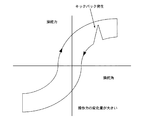
しかしながら、従来の車両用操舵装置にあっては、例えば、クランク状の交差点を走行する場合など、素早いハンドル切り返しを要するシーンのとき、ハンドル切り戻し時に路面不整等による路面からのキックバックが発生した場合、操舵力が過渡的に急増してハンドルが取られ、切り返し操舵が阻害されるという問題があった。 However, in a conventional vehicle steering device, for example, when driving at a crank-shaped intersection, a kickback from the road surface due to road surface irregularities or the like occurs when the steering wheel is turned back. In this case, there is a problem that the steering force increases transiently and the steering wheel is taken, and the turnback steering is hindered.
本発明は、上記問題に着目してなされたもので、その目的とするところは、ハンドル切り戻し時において、路面からのキックバックに伴う操舵力変化を抑制できる車両用操舵装置を提供することを目的とする。 The present invention has been made paying attention to the above problems, and an object of the present invention is to provide a vehicle steering apparatus that can suppress a change in steering force accompanying a kickback from the road surface when the steering wheel is turned back. Objective.
上記目的を達成するため、本発明では、
操舵入力を受けるハンドルと操向輪を転舵する操向輪転舵機構とが機械的に切り離されるとともに、路面から前記操向輪に作用する反力を取得し、前記ハンドルに対し前記取得した路面反力に基づく操舵反力付加量を付加する車両用操舵装置において、
前記ハンドルの切り増しと切り戻しを判定する切り増し切り戻し判定手段と、
前記ハンドルの切り戻し時には、切り増し時よりも前記操舵反力付加量を小さくする操舵反力補正手段と、
を備えることを特徴とする。
In order to achieve the above object, in the present invention,
Rutotomoni a steering wheel steering mechanism that steers the steering wheel and steered wheels for receiving a steering input is mechanically decoupled, obtains a reaction force acting on the steering wheel from the road surface, said it acquired relative to the handle In a vehicle steering device for adding a steering reaction force addition amount based on a road surface reaction force,
An increase / return determination means for determining increase / return of the handle;
Steering reaction force correction means for making the steering reaction force addition amount smaller when turning the steering wheel than when adding the steering wheel;
It is characterized by providing.
よって、本発明の車両用操舵装置にあっては、ハンドルが切り戻されているとき、取得した路面反力に基づく操舵反力付加量を小さくするため、路面からのキックバックに伴う操舵力変化が抑制され、運転者の素早い切り返し操舵を妨げないようにできる。 Therefore, in the vehicle steering apparatus of the present invention, when the steering wheel is turned back, the steering force change accompanying the kickback from the road surface is reduced in order to reduce the amount of steering reaction force addition based on the acquired road surface reaction force. Is suppressed, and it is possible to prevent the driver from turning back quickly.
以下、本発明の車両用操舵装置を実現する実施の形態を、図面に示す実施例1〜3に基づいて説明する。 Hereinafter, an embodiment for realizing a vehicle steering system of the present invention will be described based on Examples 1 to 3 shown in the drawings.
まず、構成を説明する。
図1は実施例1の車両用操舵装置を示す全体システム図、図2は実施例1の車両用操舵装置におけるクラッチ部とケーブルコラム部とトルクセンサー部の各詳細図である。実施例1の車両用操舵装置は、(1)反力装置、(2)バックアップ装置、(3)転舵装置、(4)制御コントローラにより構成されている。以下、それぞれの構成を詳しく説明する。
First, the configuration will be described.
FIG. 1 is an overall system diagram showing a vehicle steering apparatus according to a first embodiment, and FIG. 2 is a detailed view of a clutch portion, a cable column section, and a torque sensor section in the vehicle steering apparatus according to the first embodiment. The vehicle steering apparatus according to the first embodiment includes (1) a reaction force apparatus, (2) a backup apparatus, (3) a steering apparatus, and (4) a control controller. Hereinafter, each configuration will be described in detail.
(1)反力装置
反力装置は、舵角センサー1、エンコーダ2、トルクセンサー3,3、反力モータ5とを有して構成される。
(1) Reaction force device The reaction force device includes a
前記舵角センサー1は、ハンドル6の操作角を検出する手段で、後述するケーブルコラム7とハンドル6とを結合するコラムシャフト8aに設けられている。つまり、舵角センサー1は、ハンドル6とトルクセンサー3,3との間に設置されており、トルクセンサー3,3の捩れによる角度変化の影響を受けることなく、操舵角を検出できるようになっている。この舵角センサー1には、アブソリュート型レゾルバ等を用いる。
The
前記トルクセンサー3,3は二重系を成し、前記舵角センサー1と反力モータ5との間に設置されていて、トルクセンサー1とトルクセンサー2との2つのトルクセンサーにより構成されている。図2(c)にトルクセンサー部の詳細を示す。トルクセンサー3,3は、軸方向に延在するトーションバーと、該トーションバーの一端に連結され、該トーションバーと同軸をなす第1軸と、該トーションバーの他端に連結され、該トーションバーおよび第1軸と同軸を成す第2軸と、前記第1軸に固定された第1磁性体と、前記第2軸に固定された第2磁性体と、前記第1磁性体および第2磁性体に対面するコイルと、該コイルを包囲し、前記第1磁性体および第2磁性体と共に磁気回路を形成する第3磁性体とを有し、前記コイルはトーションバーに作用する捩れに基づく第1磁性体と第2磁性体との相対変位に対応してインダクタンスが変化し、該インダクタンスに基づく出力信号によりトルクを検出する。
The torque sensors 3 and 3 form a double system, and are installed between the
前記反力モータ5は、ハンドル6に反力を与える反力アクチュエータであり、前記コラムシャフト8aを回転軸とする1ロータ・1ステータの電動モータで構成されており、そのケーシングが車体の適所に固定されている。この反力モータ5としては、ブラシレスモータが使用され、ブラシレスモータの使用に伴ってエンコーダ2とホールIC(不図示)とを追加する。その場合は、ホールICのみでもモータトルクを発生するモータ駆動は可能であるが、微細なトルク変動が発生し、操舵反力感が悪い。そこで、より繊細で滑らかな反力制御を行うため、コラムシャフト8aの軸上にエンコーダ2を装着し、モータ制御を行うことで、微細なトルク変動を低減し、操舵反力感の向上させている。なお、エンコーダ2の代わりにレゾルバを用いても良い。
The reaction force motor 5 is a reaction force actuator that applies a reaction force to the handle 6. The reaction force motor 5 is composed of a 1-rotor 1-stator electric motor having the
(2)バックアップ装置
バックアップ装置は、ケーブルコラム7とクラッチ9により構成されている。
前記クラッチ9は、コラムシャフト8aとプーリシャフト8bとの間に介装され、実施例1では電磁クラッチを用いている。図2(a)にクラッチ部の詳細を示す。クラッチ9は、電磁コイルに通電されると、磁束Φが発生する。このとき、アーマチュアが板ばねの復帰力に抗してロータのフランジに磁気吸着されるから、入力軸であるコラムシャフト8aと出力軸であるプーリシャフト8bは連結される。そして、ハンドル6が回転すると、その回転力がクラッチ9を介してケーブルコラム7のプーリに伝達され、ケーブルコラム7のプーリが回転すると、その回転力がクラッチ9を介してハンドル6に伝達される。また、電磁コイルへの通電を解除すると、磁束Φが消滅してアーマチュアが板ばねの復帰力によってロータから離間する。つまり、クラッチ9の伝達トルク容量は、電磁コイルの発生できる磁束Φを変えることで吸着力が変化するので任意に設定することができる。なお、通電するとクラッチを解除する方式を採っても良い。
(2) Backup device The backup device includes a cable column 7 and a
The
前記ケーブルコラム7は、前記クラッチ9が締結されるバックアップモード時、反力装置と転舵装置との間に介在する部材との干渉を避けて迂回しながらも、トルクを伝達するコラムシャフト機能を発揮する機械式バックアップ機構である。図2(b)にケーブルコラム部の詳細を示す。ケーブルコラム7は、2つのリールに端部がリールに固定された2本のインナーケーブルを互いに逆方向へ巻き付け、2つのリールケースに2本のインナーケーブルを内挿したアウターチューブの両端を固定することにより構成されている。
In the backup mode in which the
(3)転舵装置
転舵装置は、エンコーダ10、舵角センサー11、トルクセンサー12,12、転舵モータ14,14、ステアリング機構(操向輪転舵機構)15、操向輪16,16とを有して構成される。
(3) Steering device The steering device includes an encoder 10, a steering angle sensor 11, torque sensors 12 and 12, steering motors 14 and 14, a steering mechanism (steering wheel steering mechanism) 15, and
前記舵角センサー11とトルクセンサー12,12とは、ケーブルコラム7のプーリが一端に取り付けられ、他端部にピニオンギアが形成されたピニオンシャフト17の軸上に設けられている。舵角センサー11としては、シャフトの回転数を検出するアブソリュート式レゾルバ等が用いられる。また、トルクセンサー12,12としては、上記トルクセンサー3,3と同様に二重系を成し、インダクタンスの変化によりトルクを検出するものが用いられる。そして、ケーブルコラム7側に舵角センサー11を配置し、ステアリング機構15側にトルクセンサー12,12を配置することで、舵角センサー11による転舵角検出に際してトルクセンサー12,12の捩りによる角度変化の影響を受けないようにしている。
The rudder angle sensor 11 and the torque sensors 12, 12 are provided on an axis of a
前記転舵モータ14,14は、前記ピニオンシャフト17の舵角センサー11とトルクセンサー12,12との中間位置に設けたウォームギアに噛み合うピニオンギアをモータ軸に設けることで、モータ駆動時にピニオンシャフト17に転舵トルクを付与するように構成されている。この転舵モータ14,14は、1ロータ・2ステータ構造とすることにより二重系を成し、第一転舵モータ14と第二転舵モータ14を構成するブラシレスモータとしている。また、上記反力モータ5と同様に、ブラシレスモータの使用に伴ってエンコーダ10とホールIC(図外)とを追加する。
The steering motors 14 and 14 are provided with a pinion gear that meshes with a worm gear provided at an intermediate position between the rudder angle sensor 11 and the torque sensors 12 and 12 of the
前記ステアリング機構15は、前記ピニオンシャフト17の回転により左右の操向輪16,16を転舵させる舵取り機構であって、ラックチューブ15a内に内挿され、前記ピニオンシャフト17のピニオンギアに噛み合うラックギアが形成されたラックシャフト15bと、この車両左右方向に延びるラックシャフト15bの両端部に結合されたタイロッド15c,15cと、一端が前記タイロッド15c,15cに結合され、他端が操向輪16,16に結合されたナックルアーム15d,15dと、を有して構成されている。
The
(4)制御コントローラ
制御コントローラは、2つの電源18,18により処理演算等を行う2つの制御コントローラ19,19により二重系が構成されている。
(4) Control Controller The control controller has a dual system composed of two
前記制御コントローラ19は、反力装置の舵角センサー1、エンコーダ2、トルクセンサー3,3、ホールICと、転舵装置のエンコーダ10、舵角センサー11、トルクセンサー12,12、ホールIC、車速センサー(車速検出手段)21からの検出値が入力される。
The
制御コントローラ19は、各センサーの検出値に基づいて、反力モータ5および転舵モータ14の制御量を設定し、各モータ5,14を駆動制御する。また、制御コントローラ19は、システムが正常に作動している間は、クラッチ9を解放し、システムに異常が発生した場合には、クラッチ9を締結させ、ハンドル6と操向輪16,16を機械的に連結させる。
The
次に、作用を説明する。
[反力モータ制御量算出]
制御コントローラ19では、下記の式(1)を用いて、反力モータ5の制御量Thを設定する。
Th=Kp×θ+Gf×F …(1)
ここで、Kpは操舵角分フィードバックゲイン、θは操舵角、Gfは路面反力分フィードバックゲイン、Fは路面反力であり、右辺第1項では、操舵角θに基づく操舵反力の制御量が設定され、右辺第2項では、路面反力Fに基づく制御量が設定されるため、路面からタイヤに作用する力の影響を操舵反力に反映させることができる。
Next, the operation will be described.
[Reaction force motor control amount calculation]
The
Th = Kp × θ + Gf × F (1)
Here, Kp is the feedback gain for the steering angle, θ is the steering angle, Gf is the road surface reaction force feedback gain, and F is the road surface reaction force. In the first term on the right side, the control amount of the steering reaction force based on the steering angle θ In the second term on the right side, since the control amount based on the road surface reaction force F is set, the influence of the force acting on the tire from the road surface can be reflected in the steering reaction force.
ここで、路面反力分フィードバックゲインGfは操舵状態により値が変化する。ハンドル切り増し時は、路面フィールを運転者に伝え、適度な操舵反力となるように値が設定されている。ハンドル切り戻し時には、キックバックなどの過度の力によりハンドル切り返し操作が阻害されないように、路面反力分のフィードバック量を小さめに設定されている。 Here, the value of the road surface reaction force feedback gain Gf varies depending on the steering state. When the steering wheel is increased, the road surface feel is transmitted to the driver, and the value is set so that an appropriate steering reaction force is obtained. When the steering wheel is turned back, the feedback amount corresponding to the road surface reaction force is set to be small so that the steering wheel turning operation is not hindered by an excessive force such as kickback.
路面反力分フィードバックゲインGfは、
Gf(Low)=(Low) …ハンドル切り戻し時
Gf(High)=(High) …ハンドル切り増し時
となる。(Low),(High)は、後述するマップ(図4)に基づいてそれぞれ決定するが、あらかじめ設定された定数としても良い。
The road surface reaction force feedback gain Gf is
Gf (Low) = (Low) ... When turning back the handle Gf (High) = (High) ... When turning the handle off. (Low) and (High) are respectively determined based on a map (FIG. 4) described later, but may be constants set in advance.
また、式(1)の右辺に、操舵角速度dθ/dt、操舵角加速度d2θ/dt2に基づく制御量を追加設定してもよい。この場合、反力モータ4の制御量Thは、下記の式(2)となる。
Th=Kp×θ+Kd×dθ/dt+Kdd×d2θ/dt2+Gf×F …(2)
ここで、KdおよびKddはあらかじめ設定された定数である。
Further, a control amount based on the steering angular velocity dθ / dt and the steering angular acceleration d 2 θ / dt 2 may be additionally set on the right side of the equation (1). In this case, the control amount Th of the reaction force motor 4 is expressed by the following equation (2).
Th = Kp × θ + Kd × dθ / dt + Kdd × d 2 θ / dt 2 + Gf × F (2)
Here, Kd and Kdd are preset constants.
[路面反力分フィードバックゲイン設定]
図3は、路面反力分フィードバックゲインGfの設定方法を示すフローチャートで、以下、各ステップについて説明する。
[Road surface reaction force feedback gain setting]
FIG. 3 is a flowchart showing a method for setting the road surface reaction force feedback gain Gf. Each step will be described below.
ステップS1では、舵角センサー1からの信号を読み込み、ステップS2へ移行する。
In step S1, the signal from the
ステップS2では、ステップS1で読み込んだセンサー信号から、操舵角と操舵角速度を演算し(操舵角速度検出手段に相当)、ハンドル切り戻し状態であるか否かを判定する(切り増し切り戻し判定手段に相当)。YESの場合にはステップS3へ移行し、NOの場合にはステップS4へ移行する。 In step S2, the steering angle and the steering angular velocity are calculated from the sensor signal read in step S1 (corresponding to the steering angular velocity detection means), and it is determined whether or not the steering wheel is in the state of returning the steering wheel (in the additional switching back-up determination means). Equivalent). If YES, the process proceeds to step S3. If NO, the process proceeds to step S4.
ステップS3では、路面反力分フィードバックゲインGfをLowとし(操舵反力補正手段に相当)、リターンへ移行する。 In step S3, the road surface reaction force feedback gain Gf is set to Low (corresponding to the steering reaction force correction means), and the process proceeds to return.
ステップS4では、路面反力分フィードバックゲインGfをHighとし、リターンへ移行する。 In step S4, the road surface reaction force feedback gain Gf is set to High, and the routine proceeds to return.
図4は、路面反力Fに応じた路面反力分フィードバックゲインGfの設定マップであり、ハンドル切り戻し(Low)の場合には、ハンドル切り増し(High)の場合と比較して、路面反力Fに対する路面反力分フィードバックゲインGfが小さな値に設定される。 FIG. 4 is a setting map of the road surface reaction force feedback gain Gf according to the road surface reaction force F. In the case of steering wheel return (Low), the road surface reaction is compared with the case of steering wheel increase (High). The road surface reaction force feedback gain Gf with respect to the force F is set to a small value.
[操舵状態に応じた制御量の設定]
速い切り返しが必要なときほど、運転者はハンドル切り返し操作を阻害されたくないため、実施例1では、操舵角速度dθ/dtが大きいときほど、路面反力分のフィードバック量を小さめに設定する。
[Control amount setting according to the steering state]
Since the driver does not want to be disturbed by the steering wheel turning operation when the quick turning is necessary, in the first embodiment, the feedback amount corresponding to the road surface reaction force is set to be smaller as the steering angular velocity dθ / dt is larger.
よって、路面反力分フィードバックゲインGfは、
Gf(Low)=(Low)×L1 …ハンドル切り戻し時
Gf(High)=(High) …ハンドル切り増し時
となる。
Therefore, the road surface reaction force feedback gain Gf is
Gf (Low) = (Low) × L1... When the handle is turned back Gf (High) = (High).
ここで、L1は、図5に示すマップに基づいて設定される。図5のマップにおいて、L1は、操舵角速度dθ/dtが高速走行時に発生する頻度の高い範囲のときは最大値1であり、操舵角速度dθ/dtが大きくなるほど小さな値となる。そして、操舵角速度dθ/dtが緊急回避時に発生する領域に達した場合には、最小値L1minとなるように設定されている。
Here, L1 is set based on the map shown in FIG. In the map of FIG. 5, L1 is the
[車速に応じた制御量の設定]
実施例1では、車速Vが低いときほど速い切り返しが必要なシーンが多いことから、低速域ほどハンドル切り戻し時の路面反力分フィードバック量を小さめに設定している。すなわち、高速域になるほど、ハンドル操作に対して車両挙動が敏感となるため、ハンドル切り戻し時においても路面反力分のフィードバックが必要となってくる。一方、低速域での取り回し域などでは、スムーズなハンドル操作性が必要になってくるため、この点を考慮し、車速Vが小さいほどハンドル切り戻し時の路面反力分のフィードバック量が小さくなるように設定する。
[Control amount setting according to vehicle speed]
In the first embodiment, as the vehicle speed V is lower, there are many scenes that need to be turned faster. Therefore, the feedback amount for the road surface reaction force at the time of turning back the steering wheel is set to be smaller in the low speed range. In other words, the higher the speed range, the more sensitive the vehicle behavior is to the steering wheel operation. Therefore, the feedback of the road surface reaction force is required even when the steering wheel is turned back. On the other hand, smooth steering operability is required in the handling area in the low speed range, and in consideration of this point, the feedback amount corresponding to the road surface reaction force at the time of turning back the steering wheel is reduced as the vehicle speed V is reduced. Set as follows.
よって、路面反力分フィードバックゲインGfは、
Gf(Low)=(Low)×L1×L2 …ハンドル切り戻し時
Gf(High)=(High) …ハンドル切り増し時
となる。
Therefore, the road surface reaction force feedback gain Gf is
Gf (Low) = (Low) × L1 × L2... At the time of turning back the handle Gf (High) = (High).
ここで、L2は、図6に示すマップに基づいて設定される。図6のマップにおいて、L2は、車速Vに比例して増加し、車速Vが市街地走行で頻度の高い領域に達したとき、最大値1となるように設定されている。 Here, L2 is set based on the map shown in FIG. In the map of FIG. 6, L2 increases in proportion to the vehicle speed V, and is set to a maximum value of 1 when the vehicle speed V reaches a high-frequency area in city driving.
[従来のステア・バイ・ワイヤ操舵装置の問題点]
特開平10−217988号公報に記載の車両用操舵装置では、操舵力演算器において、操舵力センサーの検出結果を基に操舵軸(ステアリングシャフト)に付与された操舵力Tを演算すると共に、操舵力Tが付与された方向に操舵軸を回転させるための制御量aT(aは操舵力ギア比に相当する係数)を演算している。
[Problems of conventional steer-by-wire steering systems]
In the vehicle steering apparatus described in Japanese Patent Application Laid-Open No. 10-217988, the steering force calculator calculates the steering force T applied to the steering shaft (steering shaft) based on the detection result of the steering force sensor, and performs steering. A control amount aT (a is a coefficient corresponding to the steering force gear ratio) for rotating the steering shaft in the direction in which the force T is applied is calculated.
転舵反力演算器では、ステアリングラックの両端に設けた転舵反力センサーの検出結果F1,F2の平均値を、転舵軸(ピニオンシャフト)に付与された転舵反力Fとしている。操舵軸モータ制御回路は、これらの演算結果を基に、操舵軸の回転制御量Mmを下記の式(3)から算出し、回転制御量Mmに応じた反力制御信号を、操舵軸モータに出力する。
Mm=Gm×(aT−F) …(3)
なお、Gmは出力信号のゲインを示すゲイン係数である。
In the turning reaction force calculator, the average value of the detection results F1 and F2 of the turning reaction force sensors provided at both ends of the steering rack is used as the turning reaction force F applied to the turning shaft (pinion shaft). Based on these calculation results, the steering shaft motor control circuit calculates the rotation control amount Mm of the steering shaft from the following equation (3), and sends a reaction force control signal corresponding to the rotation control amount Mm to the steering shaft motor. Output.
Mm = Gm × (aT−F) (3)
Gm is a gain coefficient indicating the gain of the output signal.
しかしながら、この従来技術では、転舵反力センサーによる路面反力分を操舵反力に伝える構成であるため、例えば、クランク状の交差点を走行する場合など、素早いハンドル切り返しを要するシーンのとき、路面不整(穴など)等にタイヤを落とすと、転舵反力センサーからの信号によりハンドルが取られ、素早いハンドル切り返しが阻害されるという問題があった(図7参照)。すなわち、路面からのキックバックに追従して操舵反力が付加されるため、操舵力が急に大きくなり、運転者は素早い切り返しを行うのが困難となる。 However, since this conventional technology is configured to transmit the road reaction force by the steering reaction force sensor to the steering reaction force, for example, when driving a crank-shaped intersection, the road surface If the tire is dropped in irregularities (holes, etc.), the steering wheel is taken by the signal from the steering reaction force sensor, and there is a problem that the quick steering wheel turning back is obstructed (see FIG. 7). That is, since the steering reaction force is applied following the kickback from the road surface, the steering force suddenly increases, making it difficult for the driver to perform quick turnover.
[実施例1の切り返し操舵作用]
これに対し、実施例1の車両用操舵装置では、ハンドル切り戻し時には路面反力分フィードバックゲインGfを小さくすることにより、路面不整などにより路面反力が過渡的に増加した場合でも、キックバックに伴う操舵力の変化が抑制されるため、ハンドル取られを低減できる(図8)。
[Cut-back steering action of Embodiment 1]
In contrast, in the vehicle steering system of the first embodiment, when the steering wheel is turned back, the feedback gain Gf corresponding to the road surface reaction force is reduced, so that even when the road surface reaction force increases transiently due to road surface irregularities, the kickback is performed. Since the accompanying change in steering force is suppressed, it is possible to reduce steering wheel removal (FIG. 8).
また、操舵角速度dθ/dtが大きいほど路面反力分フィードバックゲインGfを小さくするため、速い切り返しのときほどキックバックに伴う操舵力変化を抑制することで、運転者のより速い切り返しを妨げないようにできる。さらに、車速Vが低いときほど路面反力分フィードバックゲインGfを小さくするため、低速域でのハンドル取り回しの良さと、高速域での走行安定性の良さとを両立できる。 Further, since the road surface reaction force feedback gain Gf is reduced as the steering angular velocity dθ / dt increases, the change in the steering force associated with kickback is suppressed at the faster turnover so as not to prevent the driver from turning faster. Can be. Furthermore, since the road surface reaction force feedback gain Gf is reduced as the vehicle speed V is lower, both good steering performance in the low speed range and good running stability in the high speed range can be achieved.
次に、効果を説明する。
実施例1の車両用操舵装置にあっては、下記に列挙する効果が得られる。
Next, the effect will be described.
In the vehicle steering apparatus according to the first embodiment, the following effects can be obtained.
(1) 操舵入力を受けるハンドル6と操向輪16,16を転舵するステアリング機構15とが機械的に切り離され、ハンドル6に対し路面反力Fに応じた操舵反力付加量(Gf×F)を付加する車両用操舵装置において、ハンドル6の切り増しと切り戻しを判定する切り増し切り戻し判定手段と、ハンドル1の切り戻し時には、切り増し時よりも路面反力分フィードバックゲインGfを小さくする操舵反力補正手段と、を備えるため、キックバックに伴う操舵力の変化を抑制でき、ハンドル取られを低減できる。
(1) The steering wheel 6 that receives the steering input and the
(2) 操舵反力補正手段は、ハンドル1の操舵角速度dθ/dtが高いほど路面反力分フィードバックゲインGfを小さくするため、運転者のより速いハンドル切り返しを妨げないようにできる。
(2) Since the steering reaction force correction means decreases the road surface reaction force feedback gain Gf as the steering angular velocity dθ / dt of the
(3) 操舵反力補正手段は、車速Vが低いほど路面反力分フィードバックゲインGfを小さくするため、高速域における路面反力のフィードバックと、低速域における取り回しの向上とを両立できる。 (3) Since the steering reaction force correction means reduces the road surface reaction force feedback gain Gf as the vehicle speed V is lower, both the feedback of the road surface reaction force in the high speed region and the improvement of the handling in the low speed region can be achieved.
実施例2は、車両状態量に応じて路面反力フィードバック量を変化させる例である。なお、実施例2の構成は、図1,2に示した実施例1の構成と同一であるため、説明を省略する。 The second embodiment is an example in which the road surface reaction force feedback amount is changed according to the vehicle state amount. The configuration of the second embodiment is the same as the configuration of the first embodiment shown in FIGS.
次に、作用を説明する。
[車両状態量に応じた制御量の設定]
ハンドル切り戻し時に路面反力分のフィードバック量を小さめに設定すると、全体の操舵反力が軽くなり過ぎる場合がある。この場合、車両状態量としてヨーレートを算出し、路面反力分のフィードバック量相当にあたる以下のゲイン定数Gyと、路面反力分のフィードバック量の低減相当分YDを算出し、これを反力モータ4の制御量に加えることで、操舵反力が軽くなり過ぎるのを防止できる。
Next, the operation will be described.
[Setting of control amount according to vehicle state quantity]
If the feedback amount corresponding to the road surface reaction force is set smaller when the steering wheel is turned back, the overall steering reaction force may become too light. In this case, to calculate the yaw rate as the vehicle state quantity, calculates the following gain constant Gy corresponding to the feedback amount equivalent road surface reaction force, a reduction equivalent YD of the road surface reaction force amount of feedback, reaction motor 4 this By adding to the control amount, it is possible to prevent the steering reaction force from becoming too light.
実施例2では、式(2)の右辺に、車両挙動を示すヨーレートψに基づく制御量を追加設定する。よって、反力モータ5の制御量Thは、下記の式(4)となる。
Th=Kp×θ+Kd×dθ/dt+Kdd×d2θ/dt2+Ky×ψ+Gf×F …(4)
In the second embodiment, a control amount based on the yaw rate ψ indicating the vehicle behavior is additionally set on the right side of the equation (2). Therefore, the control amount Th of the reaction force motor 5 is expressed by the following equation (4).
Th = Kp × θ + Kd × dθ / dt + Kdd × d 2 θ / dt 2 + Ky × ψ + Gf × F (4)
[ヨーレート算出方法]
ヨーレートψは、操舵角θと車速Vと車両運動の数学モデルにより、下記の式(5)から得られる。
ψ={G×ωn2×Tr(s+1/Tr)×θ}/(s2+2ξωns+ω2) …(5)
ここで、
G={1/(1+A×V2)}×(V/L)
Tr=(2Lr×Kr)/(m×Lf×V)
A=−(m/2L2)×{(Lf×Kf−Lr×Kr)×(Kf×Kr)}
Lfは重心から前軸までの距離、Lrは重心から後軸までの距離、Kfは前輪のコーナリングフォース、Krは後輪のコーナリングフォース、mは車両重量、sはラプラス演算子
である。
よって、上記式(5)により得られた値を、ヨーレートψの推定値として用いる。
[Yaw rate calculation method]
The yaw rate ψ is obtained from the following equation (5) using a mathematical model of the steering angle θ, the vehicle speed V, and the vehicle motion.
ψ = {G × ωn 2 × Tr (s + 1 / Tr) × θ} / (s 2 + 2ξωns + ω 2 ) (5)
here,
G = {1 / (1 + A × V 2 )} × (V / L)
Tr = (2Lr × Kr) / (m × Lf × V)
A = − (m / 2L 2 ) × {(Lf × Kf−Lr × Kr) × (Kf × Kr)}
Lf is the distance from the center of gravity to the front axle, Lr is the distance from the center of gravity to the rear axle, Kf is the cornering force of the front wheels, Kr is the cornering force of the rear wheels, m is the vehicle weight, and s is the Laplace operator.
Therefore, the value obtained by the above equation (5) is used as the estimated value of the yaw rate ψ.
ところで、横加速度Ygとヨーレートψは、車速Vを用いて、下記の式(6)の関係が成り立つ。
Yg=ψ×V …(6)
Incidentally, the lateral acceleration Yg and the yaw rate ψ use the vehicle speed V and the relationship of the following equation (6) is established.
Yg = ψ × V (6)
また、路面反力Fは、外乱の無い定常的な円旋回を行っている場合は、下記の式(7)の関係が成り立つ。
F∝Yg …(7)
したがって、
F∝ψ×V …(7)'
の関係が成り立つ。
Further, the road surface reaction force F satisfies the relationship of the following expression (7) when a steady circular turn without disturbance is performed.
F∝Yg (7)
Therefore,
F∝ψ × V (7) '
The relationship holds.
ハンドル切り戻し時における路面反力分のフィードバック量の低減相当分YDは、図9に示すマップから、ψ×Vに対応したTfのHigh'値およびLow'値を読み取り、下記の式(8)となる(操舵反力補正量推定手段に相当)。
YD=TfHigh'−TfLow' …(8)
このYDにあらかじめ設定したゲイン定数Gyをかけた値を、反力モータ5の制御量Thに加算する。
ここで、Gy=Gfとする(図10)。
ただし、これに限ったものではなく、例えば、Gy=AGfとして、高速域ではA=1とし、低速域になるほどAの値を小さくするように設定しても良い。
The amount YD corresponding to the reduction in the feedback amount corresponding to the road surface reaction force at the time of turning back the steering wheel is read from the map shown in FIG. 9 by reading the high and low values of Tf corresponding to ψ × V, and the following equation (8) (Corresponding to a steering reaction force correction amount estimating means).
YD = T fH igh'-TfLow ' ... (8)
A value obtained by multiplying YD by a preset gain constant Gy is added to the control amount Th of the reaction force motor 5.
Here, Gy = Gf (FIG. 10).
However, the present invention is not limited to this. For example, Gy = AGf, A = 1 in the high speed range, and the value of A may be set smaller as the speed decreases.
また、YDも同様に、
YD=TfHigh'−TfLow'×L1×L2 …(8)'
としても良い。
Similarly, YD
YD = T fH igh'-T fL ow '× L1 × L2 ... (8)'
It is also good.
[実施例2の切り返し操舵作用]
図11は、実施例2の切り返し操舵作用を示す図であり、実施例2では、実施例1に対し、操舵力に路面反力分のフィードバック量相当にあたるYDが加算されるため、横加速度やヨーには影響しないような路面反力変化のとき、キックバックに伴う操舵力の変化量を低減させつつ、操舵力が軽くなり過ぎるのを防止できる。
[Turning-back steering action of embodiment 2]
FIG. 11 is a diagram illustrating the reverse steering operation of the second embodiment. In the second embodiment, YD corresponding to the feedback amount corresponding to the road surface reaction force is added to the steering force in the second embodiment, and therefore, the lateral acceleration and When the road reaction force changes so as not to affect the yaw, it is possible to prevent the steering force from becoming too light while reducing the amount of change in the steering force that accompanies kickback.
次に、効果を説明する。
実施例2の車両用操舵装置にあっては、実施例1の効果(1)〜(3)に加え、以下の効果が得られる。
Next, the effect will be described.
In the vehicle steering apparatus according to the second embodiment, the following effects can be obtained in addition to the effects (1) to (3) of the first embodiment.
(4) ヨーレートψから路面反力分のフィードバック量の低減相当分にあたるYDを推定する操舵反力補正量推定手段を備え、操舵反力補正手段は、YDが大きいほど、ヨーレートψに応じた操舵反力分を付加する(Gy×YD)ため、操舵力の変化量を低減しつつ、操舵力が軽くなる過ぎるのを防止できる。 (4) Provided with a steering reaction force correction amount estimating means for estimating YD corresponding to a reduction in the feedback amount corresponding to the road surface reaction force from the yaw rate ψ, the steering reaction force correction means steers in accordance with the yaw rate ψ as YD increases. Since the reaction force is added (Gy × YD), it is possible to prevent the steering force from becoming too light while reducing the amount of change in the steering force.
実施例3は、車両が旋回限界域にあるとき、路面反力分のフィードバック量を補正しない例である。ここで、旋回限界域とは、タイヤの横滑りが発生するような状態を言う。なお、実施例3の構成は、図1に示した実施例1の構成と同一であるため、説明を省略する。 The third embodiment is an example in which the feedback amount corresponding to the road surface reaction force is not corrected when the vehicle is in the turning limit region. Here, the turning limit region refers to a state in which a skid of the tire occurs. The configuration of the third embodiment is the same as that of the first embodiment shown in FIG.
次に、作用を説明する。
[路面反力分フィードバックゲインの設定]
図12は、実施例3の路面反力分フィードバックゲインGfの設定方法を示すフローチャートで、以下、各ステップについて説明する。
Next, the operation will be described.
[Setting of road surface reaction force feedback gain]
FIG. 12 is a flowchart illustrating a method for setting the road surface reaction force feedback gain Gf according to the third embodiment. Each step will be described below.
ステップS11では、舵角センサー11からの信号と、車速センサー21からの信号とを読み込み、ステップS12へ移行する。
In step S11, the signal from the steering angle sensor 11 and the signal from the
ステップS12では、ステップS11で読み込んだ操向輪16,16の転舵角と、車速Vと、車両のヨーレートψから、図13に示すマップを参照し、車両が旋回限界域にあるか否かを判定する(旋回限界判定手段に相当)。YESの場合にはステップS13へ移行し、NOの場合にはステップS14へ移行する。
In step S12, the map shown in FIG. 13 is referred to from the turning angle of the steered
ステップS13では、路面反力分フィードバックゲインGfを(High)に固定し、リターンへ移行する。 In step S13, the road surface reaction force feedback gain Gf is fixed to (High), and the process proceeds to return.
ステップS14では、ハンドル切り増しと切り戻しとで路面反力分フィードバックゲインGfを変化させる制御を継続し、リターンへ移行する。 In step S14, the control for changing the road surface reaction force feedback gain Gf by the steering wheel increase and the return is continued, and the process proceeds to return.
[実施例3の切り返し操舵作用]
車両が旋回限界域にある場合、運転者は修正操舵により車両挙動を修正するが、このとき、ハンドル6の切り増しと切り戻しが頻繁かつ小刻みに行われる。このような場合には、路面反力分のフィードバック量を運転者に伝えた方が、車両挙動の修正コントロールが行いやすい。
[Turning-back steering action of embodiment 3]
When the vehicle is in the turning limit area, the driver corrects the vehicle behavior by the correction steering. At this time, the steering wheel 6 is frequently turned and turned back frequently. In such a case, the vehicle behavior correction control can be performed more easily if the driver is informed of the feedback amount corresponding to the road surface reaction force.
このため、実施例3では、車両が旋回限界域にある場合には、路面反力分のフィードバック量の補正制御が解除されるため、車両挙動に応じた操舵反力を運転者に伝達できる。よって、路面反力分のフィードバック量の低減に伴い、運転者の修正操舵を妨げないようにできる。 For this reason, in the third embodiment, when the vehicle is in the turning limit region, the correction control of the feedback amount corresponding to the road surface reaction force is canceled, and thus the steering reaction force according to the vehicle behavior can be transmitted to the driver. Therefore, along with the reduction of the feedback amount for the road surface reaction force, the driver's correction steering can be prevented from being hindered.
次に、効果を説明する。
実施例3の車両用操舵装置にあっては、実施例1の効果(1)〜(3)に加え、以下の効果が得られる。
Next, the effect will be described.
In the vehicle steering apparatus of the third embodiment, the following effects are obtained in addition to the effects (1) to (3) of the first embodiment.
(5) 操向輪16,16の転舵角と車両のヨーレートψに基づいて、車両が旋回限界にあるか否かを判定する旋回限界判定手段を備え、操舵反力補正手段は、車両が旋回限界にあると判定されたとき、操舵反力付加量を小さくしないため、路面反力分のフィードバック量の低減することによって運転者の修正操舵を妨げないようにできる。
(5) The vehicle is provided with turning limit determination means for determining whether or not the vehicle is at the turning limit based on the turning angle of the steered
(他の実施例)
以上、本発明の車両用操舵装置を実施例1〜実施例3に基づき説明してきたが、具体的な構成については、これらの実施例に限られるものではなく、特許請求の範囲の各請求項に係る発明の要旨を逸脱しない限り、設計の変更や追加等は許容される。
(Other examples)
As mentioned above, although the vehicle steering device of the present invention has been described based on the first to third embodiments, the specific configuration is not limited to these embodiments, and each claim of the claims Design changes and additions are permitted without departing from the spirit of the invention.
例えば、車両状態量として横加速度を用いても良いが、一般的に、ヨーレートの方が横加速度に対して位相が進んでいるため、応答性の観点からヨーレートを用いるのが好ましい。また、実施例1では、ヨーレートを数学モデルにより算出したが、ヨーレートセンサーの検出値を用いても良い。 For example, it may be used lateral acceleration as the vehicle state quantity, but in general, since the direction of the yaw rate is advanced in phase with respect to the lateral acceleration, it is preferable to use a yaw rate in terms of responsiveness. In the first embodiment, the yaw rate is calculated using a mathematical model, but the detection value of the yaw rate sensor may be used.
1 舵角センサー
2 エンコーダ
3 トルクセンサー
5 反力モータ
6 ハンドル
7 ケーブルコラム
8a コラムシャフト
8b プーリシャフト
9 クラッチ
10 エンコーダ
11 舵角センサー
12 トルクセンサー
14 転舵モータ
15 ステアリング機構
16 操向輪
17 ピニオンシャフト
18 電源
19 制御コントローラ
20 双方向通信線
21 車速センサー
DESCRIPTION OF
Claims (5)
前記ハンドルの切り増しと切り戻しを判定する切り増し切り戻し判定手段と、
前記ハンドルの切り戻し時には、切り増し時よりも前記操舵反力付加量を小さくする操舵反力補正手段と、
を備えることを特徴とする車両用操舵装置。 Rutotomoni a steering wheel steering mechanism that steers the steering wheel and steered wheels for receiving a steering input is mechanically decoupled, obtains a reaction force acting on the steering wheel from the road surface, said it acquired relative to the handle In a vehicle steering device for adding a steering reaction force addition amount based on a road surface reaction force,
An increase / return determination means for determining increase / return of the handle;
Steering reaction force correction means for making the steering reaction force addition amount smaller when turning the steering wheel than when adding the steering wheel;
A vehicle steering apparatus comprising:
前記ハンドルの操舵角速度を検出する操舵角速度検出手段を備え、
前記操舵反力補正手段は、前記操舵角速度が高いほど前記操舵反力付加量を小さくすることを特徴とする車両用操舵装置。 The vehicle steering apparatus according to claim 1,
A steering angular velocity detecting means for detecting a steering angular velocity of the steering wheel;
The steering apparatus for a vehicle according to claim 1, wherein the steering reaction force correction means decreases the steering reaction force addition amount as the steering angular velocity increases.
車速を検出する車速検出手段を備え、
前記操舵反力補正手段は、車速が低いほど前記操舵反力付加量を小さくすることを特徴とする車両用操舵装置。 The vehicle steering apparatus according to claim 1 or 2,
Vehicle speed detection means for detecting the vehicle speed,
The steering apparatus for a vehicle according to claim 1, wherein the steering reaction force correction means reduces the steering reaction force addition amount as the vehicle speed decreases.
車両状態量として車両のヨーレートと車速との積算値、または車両の横加速度を検出する車両状態量検出手段と、
前記車両状態量から前記操舵反力付加量に対する補正量を推定する操舵反力補正量推定手段とを備え、
前記操舵反力補正手段は、前記推定された補正量に応じた操舵反力付加量を付加することを特徴とする車両用操舵装置。 The vehicle steering apparatus according to any one of claims 1 to 3,
A vehicle state quantity detecting means for detecting the integrated value or the lateral acceleration of the vehicle, the vehicle yaw rate and the vehicle speed as the vehicle state quantity,
And a steering reaction force correction amount estimation means for estimating a correction amount for the steering reaction force adding amount from the vehicle state quantity,
The vehicle steering apparatus according to claim 1, wherein the steering reaction force correction means adds a steering reaction force addition amount corresponding to the estimated correction amount.
前記操向輪の転舵角と車両のヨーレートに基づいて、車両が旋回限界にあるか否かを判定する旋回限界判定手段を備え、
前記操舵反力補正手段は、車両が旋回限界にあると判定されたとき、前記操舵反力付加量を小さくしないことを特徴とする車両用操舵装置。
The vehicle steering apparatus according to any one of claims 1 to 4, wherein:
A turning limit determination means for determining whether or not the vehicle is at a turning limit based on a turning angle of the steering wheel and a yaw rate of the vehicle;
The steering reaction force correcting means does not reduce the steering reaction force addition amount when it is determined that the vehicle is at a turning limit.
Priority Applications (7)
| Application Number | Priority Date | Filing Date | Title |
|---|---|---|---|
| JP2004350371A JP4581660B2 (en) | 2004-12-02 | 2004-12-02 | Vehicle steering system |
| CN2010101305780A CN101863285B (en) | 2004-12-02 | 2005-12-01 | Steering control apparatus and method |
| CN2005800008977A CN101421147B (en) | 2004-12-02 | 2005-12-01 | Steering control apparatus and method |
| EP05812061.9A EP1838566B1 (en) | 2004-12-02 | 2005-12-01 | Steering control apparatus and method |
| KR1020067010355A KR100803411B1 (en) | 2004-12-02 | 2005-12-01 | Steering Control Device and Method |
| US10/575,205 US7516812B2 (en) | 2004-12-02 | 2005-12-01 | Steering control apparatus and method |
| PCT/IB2005/003627 WO2006059214A2 (en) | 2004-12-02 | 2005-12-01 | Steering control apparatus and method |
Applications Claiming Priority (1)
| Application Number | Priority Date | Filing Date | Title |
|---|---|---|---|
| JP2004350371A JP4581660B2 (en) | 2004-12-02 | 2004-12-02 | Vehicle steering system |
Publications (2)
| Publication Number | Publication Date |
|---|---|
| JP2006159963A JP2006159963A (en) | 2006-06-22 |
| JP4581660B2 true JP4581660B2 (en) | 2010-11-17 |
Family
ID=36565406
Family Applications (1)
| Application Number | Title | Priority Date | Filing Date |
|---|---|---|---|
| JP2004350371A Expired - Lifetime JP4581660B2 (en) | 2004-12-02 | 2004-12-02 | Vehicle steering system |
Country Status (6)
| Country | Link |
|---|---|
| US (1) | US7516812B2 (en) |
| EP (1) | EP1838566B1 (en) |
| JP (1) | JP4581660B2 (en) |
| KR (1) | KR100803411B1 (en) |
| CN (2) | CN101421147B (en) |
| WO (1) | WO2006059214A2 (en) |
Families Citing this family (30)
| Publication number | Priority date | Publication date | Assignee | Title |
|---|---|---|---|---|
| US7604083B2 (en) * | 2005-06-07 | 2009-10-20 | Nissan Motor Co., Ltd. | Steering apparatus for a vehicle |
| GB0617052D0 (en) * | 2006-08-30 | 2006-10-11 | Agco Sa | Vehicle steering systems |
| KR100892480B1 (en) * | 2007-11-27 | 2009-04-10 | 현대자동차주식회사 | Steering Restoration Torque Estimation System |
| JP5162324B2 (en) * | 2008-05-15 | 2013-03-13 | 株式会社豊田中央研究所 | Reaction force control device and reaction force setting method |
| JP5262754B2 (en) * | 2009-01-26 | 2013-08-14 | 日産自動車株式会社 | Steering device and steering control method |
| US20100301170A1 (en) * | 2009-05-29 | 2010-12-02 | Arin Boseroy | Control system for actuation system |
| CN101901556B (en) * | 2009-05-31 | 2014-03-26 | 北京宣爱智能模拟技术股份有限公司 | Force feedback steering system for emulating control feel of steering wheel and emulated driving system of automobile |
| KR101461866B1 (en) * | 2009-12-02 | 2014-11-13 | 현대자동차 주식회사 | Steer-by-wire system and controlling method thereof |
| CN101976521B (en) * | 2010-10-12 | 2011-11-30 | 浙江大学 | Force feedback steering wheel device applied to driving simulator |
| CN102087801A (en) * | 2010-12-31 | 2011-06-08 | 北京宣爱智能模拟技术有限公司 | System and method for automatic re-centering and force feedback of steering wheel in vehicle driving simulator |
| CN102358342A (en) * | 2011-09-09 | 2012-02-22 | 杭州赛奇高空作业机械有限公司 | Four-wheel driving double-steering travelling device and method |
| EP2772410B1 (en) * | 2011-10-26 | 2017-06-14 | Nissan Motor Co., Ltd | steering control device and steering control method |
| KR101724746B1 (en) * | 2011-11-22 | 2017-04-07 | 현대자동차주식회사 | Control apparatus and method for Steering Force According to Road Surface State |
| JP5821659B2 (en) * | 2011-12-22 | 2015-11-24 | トヨタ自動車株式会社 | Vehicle steering system |
| JP5825519B2 (en) * | 2011-12-26 | 2015-12-02 | 株式会社ジェイテクト | Steering device |
| JP5880954B2 (en) * | 2012-03-22 | 2016-03-09 | 株式会社ジェイテクト | Vehicle steering system |
| CN102717826B (en) * | 2012-06-25 | 2015-08-26 | 香港生产力促进局 | Method for return control of electric power steering system for vehicle |
| JP5892255B2 (en) * | 2012-09-04 | 2016-03-23 | 日産自動車株式会社 | Stability control device |
| US9050999B2 (en) | 2013-01-25 | 2015-06-09 | Caterpillar Inc | System with smart steering force feedback |
| WO2014167631A1 (en) * | 2013-04-08 | 2014-10-16 | 三菱電機株式会社 | Steering control device, and steering control method |
| US20140343697A1 (en) | 2013-05-17 | 2014-11-20 | Caterpillar Inc. | Selectable Operating Modes for Machine Operator Input Devices |
| CN103496395A (en) * | 2013-10-09 | 2014-01-08 | 浙江达世元电动科技有限公司 | Electric steering system and electric steering control method for new-energy automobile |
| CN205484398U (en) * | 2015-12-25 | 2016-08-17 | 罗伯特·博世有限公司 | Sensing device , sensing system and a steering system |
| CN105564527B (en) * | 2016-01-07 | 2018-04-10 | 哈尔滨理工大学 | A kind of the steering-by-wire manoeuvring platform and method of operating of the manned legged type robot of heavy type |
| JP2018008570A (en) * | 2016-07-12 | 2018-01-18 | 株式会社ジェイテクト | Control device of steering mechanism |
| JP2019064399A (en) * | 2017-09-29 | 2019-04-25 | 株式会社Subaru | Steering device |
| KR102106290B1 (en) * | 2018-09-21 | 2020-05-04 | 주식회사 만도 | Method for generating steering wheel reaction torque in SBW system and Apparatuses thereof |
| DE102018126337A1 (en) * | 2018-10-23 | 2020-04-23 | Schaeffler Technologies AG & Co. KG | Electromechanical steering arrangement and method for operating a steering arrangement |
| JP7221743B2 (en) * | 2019-03-07 | 2023-02-14 | トヨタ自動車株式会社 | vehicle control system |
| EP4474246A1 (en) * | 2022-02-03 | 2024-12-11 | JTEKT Corporation | Steering control device |
Citations (5)
| Publication number | Priority date | Publication date | Assignee | Title |
|---|---|---|---|---|
| JPH10230861A (en) * | 1997-02-19 | 1998-09-02 | Koyo Seiko Co Ltd | Vehicular steering device |
| JP2002046639A (en) * | 2000-08-07 | 2002-02-12 | Koyo Seiko Co Ltd | Steering device for vehicle |
| JP2003154948A (en) * | 2001-11-21 | 2003-05-27 | Koyo Seiko Co Ltd | Steering device for vehicle |
| JP2004051022A (en) * | 2002-07-22 | 2004-02-19 | Honda Motor Co Ltd | Driving operation device of vehicle |
| JP2004182058A (en) * | 2002-12-03 | 2004-07-02 | Toyoda Mach Works Ltd | Steering control device |
Family Cites Families (8)
| Publication number | Priority date | Publication date | Assignee | Title |
|---|---|---|---|---|
| DE19923012A1 (en) * | 1999-05-20 | 2000-11-23 | Zahnradfabrik Friedrichshafen | Steering device for car with steerable wheels has device for determination of transverse slip occurring at steerable wheels and in electronic control device, upper threshold for this determined |
| JP3696466B2 (en) * | 2000-01-31 | 2005-09-21 | 光洋精工株式会社 | Vehicle steering system |
| EP1316490B1 (en) * | 2001-11-23 | 2006-03-15 | Conception et Développement Michelin S.A. | Electric steering for vehicles |
| JP3935409B2 (en) * | 2002-08-27 | 2007-06-20 | 富士重工業株式会社 | Electric power steering device |
| JP3894886B2 (en) * | 2002-12-27 | 2007-03-22 | 本田技研工業株式会社 | Vehicle steering system |
| JP4286834B2 (en) * | 2003-05-16 | 2009-07-01 | 三菱電機株式会社 | Steering control device |
| JP3867682B2 (en) * | 2003-05-29 | 2007-01-10 | 日産自動車株式会社 | Vehicle steering system |
| JP4242233B2 (en) * | 2003-08-22 | 2009-03-25 | 富士重工業株式会社 | Steering control device |
-
2004
- 2004-12-02 JP JP2004350371A patent/JP4581660B2/en not_active Expired - Lifetime
-
2005
- 2005-12-01 KR KR1020067010355A patent/KR100803411B1/en active IP Right Grant
- 2005-12-01 EP EP05812061.9A patent/EP1838566B1/en active Active
- 2005-12-01 CN CN2005800008977A patent/CN101421147B/en active Active
- 2005-12-01 WO PCT/IB2005/003627 patent/WO2006059214A2/en active Application Filing
- 2005-12-01 CN CN2010101305780A patent/CN101863285B/en active Active
- 2005-12-01 US US10/575,205 patent/US7516812B2/en active Active
Patent Citations (5)
| Publication number | Priority date | Publication date | Assignee | Title |
|---|---|---|---|---|
| JPH10230861A (en) * | 1997-02-19 | 1998-09-02 | Koyo Seiko Co Ltd | Vehicular steering device |
| JP2002046639A (en) * | 2000-08-07 | 2002-02-12 | Koyo Seiko Co Ltd | Steering device for vehicle |
| JP2003154948A (en) * | 2001-11-21 | 2003-05-27 | Koyo Seiko Co Ltd | Steering device for vehicle |
| JP2004051022A (en) * | 2002-07-22 | 2004-02-19 | Honda Motor Co Ltd | Driving operation device of vehicle |
| JP2004182058A (en) * | 2002-12-03 | 2004-07-02 | Toyoda Mach Works Ltd | Steering control device |
Also Published As
| Publication number | Publication date |
|---|---|
| EP1838566A2 (en) | 2007-10-03 |
| WO2006059214A2 (en) | 2006-06-08 |
| CN101863285B (en) | 2012-03-07 |
| JP2006159963A (en) | 2006-06-22 |
| EP1838566B1 (en) | 2017-02-15 |
| CN101421147A (en) | 2009-04-29 |
| WO2006059214A3 (en) | 2009-04-16 |
| EP1838566A4 (en) | 2016-02-17 |
| KR100803411B1 (en) | 2008-02-13 |
| US20080230300A1 (en) | 2008-09-25 |
| US7516812B2 (en) | 2009-04-14 |
| KR20070007768A (en) | 2007-01-16 |
| CN101421147B (en) | 2010-09-15 |
| CN101863285A (en) | 2010-10-20 |
Similar Documents
| Publication | Publication Date | Title |
|---|---|---|
| JP4581660B2 (en) | Vehicle steering system | |
| JP3493568B2 (en) | Car steering system | |
| JP4604566B2 (en) | Vehicle steering system | |
| JP5327331B2 (en) | Electric power steering device for vehicle | |
| WO2017002570A1 (en) | Control device for power steering device, and power steering device | |
| US20080249685A1 (en) | Steering Control Apparatus and Method | |
| US10807637B2 (en) | Steering control device | |
| JP5860568B2 (en) | Power steering device and control device used therefor | |
| JP4640473B2 (en) | Vehicle steering device | |
| JP5141311B2 (en) | Vehicle control device | |
| JP5416722B2 (en) | Electric power steering device | |
| JP3176900B2 (en) | Vehicle steering system | |
| JP2940371B2 (en) | Auxiliary steering angle control device for vehicles | |
| JP4419932B2 (en) | Vehicle steering control device | |
| JP4626375B2 (en) | Vehicle steering control device | |
| JP6467175B2 (en) | Electric power steering device | |
| JP5427796B2 (en) | Electric power steering device | |
| JP4492289B2 (en) | Power steering device | |
| JP5427797B2 (en) | Electric power steering device | |
| JP4876433B2 (en) | Vehicle steering control device | |
| JP2008189006A (en) | Electric power steering device | |
| JP2005193779A (en) | Vehicle steering device | |
| JP2011084157A (en) | Electric power steering device | |
| KR102552648B1 (en) | Method and Device for Generating Steering Wheel Reaction Torque Signal in SBW system, and SBW Steering Device with the same | |
| JP2004090878A (en) | Motor-driven power steering device |
Legal Events
| Date | Code | Title | Description |
|---|---|---|---|
| A621 | Written request for application examination |
Free format text: JAPANESE INTERMEDIATE CODE: A621 Effective date: 20071029 |
|
| A977 | Report on retrieval |
Free format text: JAPANESE INTERMEDIATE CODE: A971007 Effective date: 20091218 |
|
| A131 | Notification of reasons for refusal |
Free format text: JAPANESE INTERMEDIATE CODE: A131 Effective date: 20100302 |
|
| A521 | Request for written amendment filed |
Free format text: JAPANESE INTERMEDIATE CODE: A523 Effective date: 20100412 |
|
| TRDD | Decision of grant or rejection written | ||
| A01 | Written decision to grant a patent or to grant a registration (utility model) |
Free format text: JAPANESE INTERMEDIATE CODE: A01 Effective date: 20100803 |
|
| A01 | Written decision to grant a patent or to grant a registration (utility model) |
Free format text: JAPANESE INTERMEDIATE CODE: A01 |
|
| A61 | First payment of annual fees (during grant procedure) |
Free format text: JAPANESE INTERMEDIATE CODE: A61 Effective date: 20100816 |
|
| R150 | Certificate of patent or registration of utility model |
Ref document number: 4581660 Country of ref document: JP Free format text: JAPANESE INTERMEDIATE CODE: R150 Free format text: JAPANESE INTERMEDIATE CODE: R150 |
|
| FPAY | Renewal fee payment (event date is renewal date of database) |
Free format text: PAYMENT UNTIL: 20130910 Year of fee payment: 3 |