JP4574468B2 - Image forming apparatus - Google Patents
Image forming apparatus Download PDFInfo
- Publication number
- JP4574468B2 JP4574468B2 JP2005193047A JP2005193047A JP4574468B2 JP 4574468 B2 JP4574468 B2 JP 4574468B2 JP 2005193047 A JP2005193047 A JP 2005193047A JP 2005193047 A JP2005193047 A JP 2005193047A JP 4574468 B2 JP4574468 B2 JP 4574468B2
- Authority
- JP
- Japan
- Prior art keywords
- image forming
- toner bottle
- forming apparatus
- leaf spring
- chip
- Prior art date
- Legal status (The legal status is an assumption and is not a legal conclusion. Google has not performed a legal analysis and makes no representation as to the accuracy of the status listed.)
- Expired - Fee Related
Links
Images


Landscapes
- Dry Development In Electrophotography (AREA)
Description
本発明は、本体に対して回転操作で着脱可能なトナーボトルを有する複写機やファクシミリ、レーザービームプリンタ等の画像形成装置に関する。 The present invention relates to an image forming apparatus such as a copying machine, a facsimile machine, or a laser beam printer having a toner bottle that can be attached to and detached from a main body by a rotating operation.
電子写真プロセスにより画像形成を行う画像形成装置では、画像形成の際、トナーを消費する。これによりトナーは補給される必要があるが,近年の補給の形態として、トナー収容器とプロセスカートリッジとをそれぞれ独立した構成とし、どちらも画像形成装置本体に対して着脱可能な構造としている。これに伴い、トナー収容器には使用量あるいは使用限界の管理データ等の情報をそのトナー収容器特有の情報としてトナー収容器に取り付けたメモリチップに記憶させておくことが実施されている。このメモリチップへの情報の読み出し、書き込みはトナー収容器を装置本体に装着したときに行うため、トナー収容器を装置本体に固定することと装置本体とメモリチップを電気的に接続する必要がある。特にトナー収容器が円筒形状の場合、トナー収容器を装置本体と固定させる場合,トナー収容器を回転させるため、メモリチップと接続する装置本体に取り付けられた端子がメモリチップの端部やメモリチップを固定するリブと回転時に接触し、端子形状の変形や破損が生じ接触不良を生じる場合がある。 In an image forming apparatus that forms an image by an electrophotographic process, toner is consumed when the image is formed. Thus, the toner needs to be replenished. However, as a form of replenishment in recent years, the toner container and the process cartridge are independent from each other, and both are detachable from the image forming apparatus main body. Along with this, information such as usage amount or usage limit management data is stored in a memory chip attached to the toner container as information unique to the toner container. Since reading and writing of information to the memory chip is performed when the toner container is mounted on the apparatus main body, it is necessary to fix the toner container to the apparatus main body and to electrically connect the apparatus main body and the memory chip. . In particular, when the toner container is cylindrical, when fixing the toner container to the apparatus main body, the terminal attached to the apparatus main body connected to the memory chip is connected to the end of the memory chip or the memory chip to rotate the toner container. Contact with the ribs that fix the terminal during rotation may cause deformation or breakage of the terminal shape, resulting in poor contact.
着脱可能な円筒形の補給用トナーボトルを有する画像形成装置において、上記補給用トナーボトルの取っ手を回転させることにより固定させる構成にて、トナーボトル設置前に、トナーボトル本体内のトナー量はトナーボトルの樹脂ケースに設置されたIDチップに、電子情報として入力されている。そして、トナーボトルがプリンタ本体にセットされると、中継コネクタが、IDチップに入力されたトナー量の情報を読み込むことにより、トナーボトル本体内のトナー量を判断する構成が知られている(例えば、特許文献1参照)。 In the image forming apparatus having a detachable cylindrical replenishing toner bottle, the amount of toner in the toner bottle main body is determined by the configuration in which the replenishing toner bottle handle is fixed by rotating. Electronic information is input to the ID chip installed in the resin case of the bottle. A configuration is known in which when the toner bottle is set in the printer body, the relay connector reads the toner amount information input to the ID chip, thereby determining the toner amount in the toner bottle body (for example, , See Patent Document 1).
しかし、補給用トナーボトルを固定させるための回転時における端子がメモリチップの端部やメモリチップを固定するリブと回転時に接触し、操作の円滑を欠き、端子形状の変形や破損が生じ接触不良を生じるという問題及び対策については記載がない。 However, the rotating terminal for fixing the replenishing toner bottle contacts the edge of the memory chip or the rib for fixing the memory chip during the rotation, so that the operation is not smooth and the terminal shape is deformed or damaged, resulting in poor contact. There is no description about the problem and measures to cause
本発明は、円筒形状のトナーボトルを当該画像形成装置本体に対して回転して装着する際に、該記録部と接続される本体側端子の損傷を回避して円滑な操作を可能にすることのできる画像形成装置を提供することを課題とする。 According to the present invention, when a cylindrical toner bottle is rotated and attached to the main body of the image forming apparatus, damage to a main body side terminal connected to the recording unit can be avoided and smooth operation can be performed. An object of the present invention is to provide an image forming apparatus capable of performing the above.
本発明は、前記課題を達成するため、請求項1では、円筒形の補給用トナーボトルを有する画像形成装置であって、前記補給用トナーボトルに枢着されたケースを回転操作することにより当該画像形成装置に取り付ける構成を有し、前記ケースに、該補給用トナーボトルの情報を出入力することが可能な記録部が設けられ、前記画像形成装置本体側に該記録部に対して電気的に接続される導通手段を具備した画像形成装置において、
前記導通手段を、前記補給用トナーボトルの軸心方向からみてV字形折曲形状をなす板ばねで構成し、
この板ばねの頂部を前記補給用トナーボトルの周面に対向させた態様で、かつ、該板ばねの一端側を、前記画像形成装置側の固定部に固定すると共に、該板ばねの他端側を、前記補給用トナーボトルと対向配置されて前記画像形成装置と一体的な板状片の、前記補給用トナーボトルからみて裏側に、固定することなく該板ばねの弾性で接するように構成し、
前記ケースの回転と共に前記補給用トナーボトルの円周方向に設けられた前記記録部が前記板ばねの前記頂部に至る斜面部を乗り上げて前記頂部に対向する状態となるとき、前記板ばねの前記頂部が前記記録部により押圧されることにより該板ばねは前記固定部を支点として前記他端側が前記板状片から離間する方向に弾性変形し、該弾性変形の押圧力により前記記録部と前記板ばね間で導通を得ることとした。
請求項2では、請求項1記載の画像形成装置において、前記板ばねの先端部がR形状又はV字形状とした。
請求項3では、請求項1又は2記載の画像形成装置において、前記記録部を保持する保持部材の、前記トナーボトルを固定するための回転時における前記導通手段との接触部をR形状とした。
また、以下の技術的特徴を有している。
円筒形の補給用トナーボトルを有する画像形成装置であって、前記補給用トナーボトルに枢着されたケースを回転操作することにより当該画像形成装置に取り付ける構成を有し、前記ケースに、該補給用トナーボトルの情報を出入力することが可能な記録部が設けられ、前記画像形成装置本体側に該記録部に対して電気的に接続される導通手段を具備した画像形成装置において、前記記録部が前記補給用トナーボトルの円周方向に設けられると共に前記導通手段が、前記記録部に弾性的に変位して接続される可変位導通手段で構成されたこととした。ここで、前記可変位導通手段を折曲形状の板ばねで構成するとよい。その際、板ばねの先端部をR形状又はV字形状に形成するとよい。また、前記可変位導通手段を弾性手段で押圧された軸状体で構成することができる。この場合も、軸状体の先端部をR形状にすることができる。さらに、前記記録部を保持する保持部材の、前記トナーボトルを固定するための回転時における前記導通手段との接触部をR形状にするのがよい。
In order to achieve the above object, the present invention provides an image forming apparatus having a cylindrical replenishing toner bottle according to claim 1 by rotating a case pivotally attached to the replenishing toner bottle. The case is configured to be attached to an image forming apparatus, and the case is provided with a recording unit capable of inputting / outputting information of the toner bottle for replenishment, and the image forming apparatus main body side is electrically connected to the recording unit. In the image forming apparatus provided with the conduction means connected to
The conduction means is constituted by a leaf spring having a V-shaped bent shape when viewed from the axial direction of the toner bottle for replenishment;
The top portion of the leaf spring is opposed to the peripheral surface of the replenishing toner bottle, and one end side of the leaf spring is fixed to the fixing portion on the image forming apparatus side, and the other end of the leaf spring is fixed. A plate-like piece that is disposed opposite to the replenishing toner bottle and is integral with the image forming apparatus is configured to come into contact with the back side of the replenishing toner bottle without being fixed by the elasticity of the leaf spring. And
When the recording portion provided in the circumferential direction of the replenishing toner bottle rides on the slope portion reaching the top of the leaf spring and faces the top as the case rotates, the leaf spring When the top portion is pressed by the recording portion, the leaf spring is elastically deformed in a direction in which the other end side is separated from the plate-shaped piece with the fixed portion as a fulcrum, and the pressing force of the elastic deformation causes the recording portion and the recording portion to be elastically deformed. It was decided to obtain conduction between the leaf springs.
According to a second aspect of the present invention, in the image forming apparatus according to the first aspect, the tip of the leaf spring has an R shape or V shape.
According to a third aspect of the present invention, in the image forming apparatus according to the first or second aspect , the contact portion of the holding member that holds the recording portion with the conduction means during rotation for fixing the toner bottle has an R shape. .
In addition, it has the following technical features.
An image forming apparatus having a cylindrical toner bottle for replenishment, wherein the case is attached to the image forming apparatus by rotating a case pivotally attached to the toner bottle for replenishment. In the image forming apparatus, a recording unit capable of inputting / outputting information of the toner bottle is provided, and the image forming apparatus main body side includes a conduction unit electrically connected to the recording unit. And the conducting means is composed of variable-position conducting means that is elastically displaced and connected to the recording part. Here, the variable position conducting means may be formed of a bent leaf spring. In that case, it is good to form the front-end | tip part of a leaf | plate spring in R shape or V shape. Further, the variable position conducting means can be constituted by a shaft-like body pressed by an elastic means. Also in this case, the tip of the shaft-like body can be formed into an R shape. Further, it is preferable that the contact portion of the holding member that holds the recording portion with the conducting means during rotation for fixing the toner bottle is formed in an R shape.
この発明では、記録部と接続される本体側端子の損傷を回避して円滑な操作を可能にする画像形成装置を提供することができる。板ばねの弾性変形時における支点となる固定側のと反対側である他端部は、常に同じ位置に復元するので、記録部に対する該板ばねの接触態様は常に安定し、記録部と板ばね間での導通、非導通の切り換えをトナーボトルの取り付け取り外し動作と連動させて安定して行なうことができる。 According to the present invention, it is possible to provide an image forming apparatus capable of avoiding damage to the main body side terminal connected to the recording unit and enabling smooth operation. Since the other end, which is the opposite side to the fixed side, which is a fulcrum when the leaf spring is elastically deformed, is always restored to the same position, the contact mode of the leaf spring with respect to the recording portion is always stable. Switching between conduction and non-conduction between the two can be performed stably in conjunction with the operation of attaching and removing the toner bottle.
以下に、この発明の実施の形態を説明する。
[1]画像形成装置
図1は本発明に係るフルカラー画像形成装置の概略構成を示す断面図である。図1に示すY(イエロー)、C(シアン)、M(マゼンタ)、K(ブラック)の4色の作像装置10Y、10C、10M、10Kが画像形成放置本体に対して着脱自在になっており、レーザー光を照射可能な露光手段としての光学ユニット20、中間転写ユニット30、給紙ユニット40、および定着ユニット50などを備えている。
各作像装置10Y、10C、10M、10Kの構造は同一であり、それぞれ感光体ドラム12、これに作用するプロセス手段として、感光体ドラムを帯電する帯電装置13、感光体ドラムに残留した現像剤等を除去するクリーニング装置15が一体的に構成されており、これに感光体ドラムに形成された潜像を現像する現像装置14が連結する構成になっている。また、各作像装置10Y、10C、10M、10Kは、紙面と垂直な方向に開閉する図示省略の面板の開閉方向に(感光体の回転軸方向、つまり紙面と垂直な方向)に画像形成装置本体に対して着脱自在な構成になっている。
Embodiments of the present invention will be described below.
[1] Image Forming Apparatus FIG. 1 is a sectional view showing a schematic configuration of a full color image forming apparatus according to the present invention. The four-color
The
中間転写ユニット30は中間転写体としての転写ベルト31、該転写ベルト31を回転可能に支持する3つのローラ32、33、34、各感光体ドラム12に形成されたトナー像を転写ベルト31に転写する一次転写ローラ35、及び転写ベルト31上に転写されたトナー像をさらに記録紙Pに転写する2次転写ユニット36を備えている。
The
給紙ユニット40は、給紙カセット41或いは手差し給紙トレイ42から記録紙Pを2次転写領域に搬送する給紙ローラ43、レジストローラ44などを備えている。
The
定着ユニット50は、定着ローラ51および加圧ローラ52を備え、記録紙P上のトナー像に熱と圧を加える事で定着を行う。定着ユニットによって定着された記録紙Pは排紙ローラ55によって排紙トレイ56に排紙される。
The
[2]トナーボトル及びその収容器
次にトナー収容器であるトナーボトル及びその収容器について説明する。図1において中間転写ユニット30と、これよりも上方にある排紙トレイ56との間にトナーボトル収容器70が配設されている。このトナーボトル収容器70は、Y(イエロー)、C(シアン)、M(マゼンタ)、K(ブラック)の4色のトナーを内包するトナーボトル71Y、71C、71M、71Kを着脱可能に収容している。トナーボトル71Y、71C、71M、71Kはトナーボトル収容器70に上から置いて回転させて固定する。これらのトナーボトル71Y、71C、71M、71Kは作像装置10Y、10C、10M、10Kとは独立して装置本体に対して着脱自在となっている。
[2] Toner bottle and its container Next, a toner bottle as a toner container and its container will be described. In FIG. 1, a
他のトナーボトルでも同じであるが、ここでは一例としてトナーボトル収容器70でのトナーボトル71Yの装着状態を図2及び図3に示す。これら図に示すように、トナーボトル71Yは、ボトル本体の先端部に樹脂ケース74Yがトナーボトル71Yに対して回転可能に設けられている。また、樹脂ケース74Yには取っ手75Yが一体で形成されている。
The same applies to the other toner bottles, but here, as an example, the mounting state of the
図1、図2に示したように、トナーボトル収容器70はそのトナーボトル収容部が断面形状でトナーボトル71Yの周面に沿うU字状をしていて、該U字状部にトナーボトル71Yを上から置くように収めて装着したとき、樹脂ケース74に形成された段部81(図6参照)の回転方向上に、トナーボトル収容器70と一体に設けられたストッパ82が位置する状態となる。
As shown in FIGS. 1 and 2, the
取っ手75に手を掛けて矢印80で示す向きに回動させる。これに伴い取っ手75Yと一体に構成された樹脂ケース74Yが回転する。段部81がストッパ82(図6参照)に当接するまで角度θ(例えばθ=30度乃至45度程度の範囲で定めた適宜の角度)回転するまでに樹脂ケース74Yに取り付けられたシャッタ(不図示)が周方向に移動し、トナー補給口が開放されると同時に樹脂ケース74Yとトナーボトル収容器70とが連結して固定される。
A hand is put on the
トナーボトル71Yを画像形成装置から取り外す際は、取っ手75Yを逆方向に回転させることで樹脂ケース74Yとトナーボトル収容器70との連結が解除され、同時にシャッタが閉じてトナー排出口が閉鎖される。そして、そのまま、取っ手75Yを掴んだ状態でトナーボトル71Yをトナーボトル収容器70(画像形成装置)から取り外すことができる。
When removing the
一方、トナーボトル71Yはトナーボトル収容器70の前記U字状の載置部で載置された状態で図示省略の動力伝達手段と連結されて回転力を与えられる状態となる。回転は、樹脂ケース74Yとの枢着部で摺接し、かつ、上記U状部のローラで支持されてなされる。樹脂ケース74Yには図4、図5に示すように、該樹脂ケース74Yの周方向に記録部としてのメモリチップ(以下、IDチップという。)76が取り付けられている。このIDチップ76にはそのトナーボトルにおけるトナー使用量あるいは使用限界の管理データ等の情報がそのトナーボトル特有の情報として記憶されている。
On the other hand, the
上記したように、樹脂ケース74Yを回転させてトナーボトル収容器70に固定する際、段部81がストッパ82に当接するとき、トナーボトル収容器70側に取り付けられた端子である板ばね90がIDチップ76に当接し電気的に接続される。板ばね90は弾性的に変位可能であり、トナーボトル収容器70に取り付けられたIDチップコネクタ77に設けられていて、弾性的に変位する可変位導通手段の一例である。こうして板ばね90は弾性的に変位してIDチップ76に対して電気的に接続した状態になりIDチップ76に記録された情報を画像形成装置本体へと送ることが可能となる。
As described above, when the
IDチップ76は板状であり図4、図5、図6等に示すように、IDチップ76の縁部が額縁状に盛り上がった構成の保持部材92により保持されている。保持部材92は樹脂ケース74Yと一体に形成されていて、矢印80で示す回転方向上で対向する保持部92aと保持部92bからなり、これら保持部92aと保持部92bに形成された溝部にIDチップ76が嵌合して保持されている。
The
これら保持部92aと保持部92bの中、回転方向80での下流側に位置する保持部92aについては、樹脂ケース74Yと共に回転移動する際、板ばね90が摺擦して弾性的に変位して無理な力を受けることなくスムーズに通過できるように、該接触部がR状に形成されている。
Of these holding
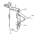
板ばね90はIDチップ76と接触する部分が図7、図8に示すようにV字形に折曲された形状をしている。図7中、板ばね90の一端部に形成された穴は該板ばね90を固定するためのねじ穴でありIDチップコネクタの一部を構成する板状片77aの外側(図中、板状片77aの右側)に固定されている。板ばね90の他端部はIDチップコネクタ77の一部を構成する板状片77bの内側(図中、板状片77bの左側)に固定されることなく接している。その上で、矢印方向からV字状に折曲された頂部に荷重W1が加わると、板ばね90は板状片77aに対する固定部を支点として他端側(板状片77bに接している側)が矢印Z方向に弾性変形し、荷重W1が無くなると元の位置に戻る。なお、板ばね90は図8に示すようにV字状の先端部をR状に形成すれば、保持部92aとの当接が滑らかとなる。
The
以上により、IDチップ76をトナーボトルの回転周方向に取り付けることにより、取っ手75Yを回転させることだけで、トナーボトル71Yをトナーボトル収容器70に固定すると同時に、IDチップ76を画像形成装置本体側に電気的に接続するようになり、トナーボトルの固定と電気的な接続を同時に行うことができ、ユーザー操作を簡単化することができる。
As described above, by attaching the
さらに、導通手段が可変位導通手段であり、この可変位導通手段が弾性変位する例えば板ばね90であるので、保持部92aに対して変位して乗り越えるので該板ばね90は損傷を受けず、また、取っ手の操作を円滑に行なうことができると共に、電気的な接触導通も良好であり、かつ、接触部の部材の損傷も少ない。
Furthermore, since the conducting means is a variable conducting means, and the variable conducting means is, for example, a
また、V字状の板ばねで構成したので、保持部92aをV字の斜面が滑ることで無理なく乗り越えることができる。また、図8の例では先端部形状がR形状であるので、より円滑に保持部92aを乗り越える(後述する図10、図11の態様でも同様である。)。また、保持部92aについても板ばね90との接触部をR形状にしたので一層円滑な動きが可能となり板ばね90を傷めることなく操作性が向上する。
Moreover, since it comprised with the V-shaped leaf | plate spring, it can ride over the holding |
次に、板ばね90を保持しているIDチップコネクタ77を説明する。図9に示すように、IDチップコネクタ77はIDチップ76と接続する端子である板ばね90とそれを内包する樹脂材で構成されている。本例では、板ばね90は4列設けられている。
Next, the
図6において、トナーボトル71Yの回転時にIDチップ76とIDチップコネクタ77の板ばね90が接触する前にIDチップ76を樹脂ケース74Y(トナーボトル71Y)に固定する保持部92aがIDチップコネクタの端子である板ばね90と最初に接触することがわかる。前記したように、保持部92aをR形状としたことにより、IDチップ76と電気的に接続されるIDチップコネクタ77の端子である板ばね90をスムーズに案内することができ、樹脂ケース74を回転してのトナーボトル71Y保持時(回転時)にIDチップ76と板ばね90との接続を円滑に行うことができ、端子形状の変形、破損を防ぎ、より確実な電気的接続が可能となる。
図10、図11は、IDチップコネクタの変形例として一列分の板ばねを保持するIDチップコネクタを示す。IDチップコネクタ77’にはV字状に折曲された板ばね90’が設けられている。この板ばね90’はV状に折曲された板状片の一端側が円弧状に湾曲していて、この湾曲部がIDチップコネクタ77’に適宜の手段で保持されている。そして、これら湾曲部からV字状折曲部に至る境界部(図10に丸印150で示した箇所)がIDチップコネクタ77’に挟み込まれて支持されている。この板ばね90’のV字状に折曲された他端側は前記した図7、図8におけると同じように板状片77’bの内側に固定されることなく接している。本例においても、矢印方向から荷重W1が加わると板ばね90’は丸印150の部位を支点として他端側(板状片77’b側)が矢印Z方向に弾性変形し、荷重W1が無くなると元の位置に戻る。
In FIG. 6, the
10 and 11 show an ID chip connector that holds one row of leaf springs as a modification of the ID chip connector. The
次に参考例としてのIDチップコネクタ770を図12により説明する。この例では、前記例におけるIDチップコネクタ77の端子としての可変位導通手段たる板ばね90に代えて、可変位導通手段を、弾性手段としての伸張性のばね100で押圧された軸状体104で構成した。
Next will be described an
軸状体104は金属ピンで構成され、IDチップコネクタ770と一体的なばね受材102との間に介在するばね100で押圧され、軸状体104はIDチップコネクタ770と一体的なガイド106に摺動可能に装着されている。図示されるように、軸状体104の後端部は大径になっていてストッパを構成し、このストッパ部がガイド106に当接することでばね100の押圧による軸状体104の抜け止めがなされている。
The shaft-
こうして、トナーボトル71Yが固定のために回転されるとき、軸状体104はばね100により弾性的に変位して保持部92aを乗り越えてIDチップ76に対して電気的に接続される。軸状体104の図中左端に相当する先端部はR形状にしてある。このように、軸状体104が弾性的に伸縮可能な構成となっていることにより、トナーボトル回転時にIDチップ76を固定する保持部92aに接触する際に弾性手段で押圧される軸状体104自体が変形することなく位置を変位するだけであるので、板ばねの場合よりも良好な電気的接続を長期確保できる。トナーボトル回転時の保持部92aとの接触によるピン形状の変形、破損を防ぐことができる。
Thus, when the
また、この軸状体104の先端の形状をR形状としたので、IDチップ76を固定する保持部92aとの接触をより円滑に行うことが可能となり、よりスムーズにIDチップと軸状体104とが電気的に接触することができる。
Further, since the shape of the tip of the shaft-
76 IDチップ(メモリチップ)
77、77’、770 記録部としてのIDチップコネクタ
71Y、M、C、K トナーボトル
90 板ばね
76 ID chip (memory chip)
77, 77 ', 770
Claims (3)
前記導通手段を、前記補給用トナーボトルの軸心方向からみてV字形折曲形状をなす板ばねで構成し、
この板ばねの頂部を前記補給用トナーボトルの周面に対向させた態様で、かつ、該板ばねの一端側を、前記画像形成装置側の固定部に固定すると共に、該板ばねの他端側を、前記補給用トナーボトルと対向配置されて前記画像形成装置と一体的な板状片の、前記補給用トナーボトルからみて裏側に、固定することなく該板ばねの弾性で接するように構成し、
前記ケースの回転と共に前記補給用トナーボトルの円周方向に設けられた前記記録部が前記板ばねの前記頂部に至る斜面部を乗り上げて前記頂部に対向する状態となるとき、前記板ばねの前記頂部が前記記録部により押圧されることにより該板ばねは前記固定部を支点として前記他端側が前記板状片から離間する方向に弾性変形し、該弾性変形の押圧力により前記記録部と前記板ばね間で導通を得ることを特徴とする画像形成装置。 An image forming apparatus having a cylindrical toner bottle for replenishment, wherein the case is attached to the image forming apparatus by rotating a case pivotally attached to the toner bottle for replenishment. In an image forming apparatus provided with a recording unit capable of inputting / outputting information of a toner bottle for use, and having a conduction unit electrically connected to the recording unit on the image forming apparatus main body side,
The conduction means is constituted by a leaf spring having a V-shaped bent shape when viewed from the axial direction of the toner bottle for replenishment;
The top portion of the leaf spring is opposed to the peripheral surface of the replenishing toner bottle, and one end side of the leaf spring is fixed to the fixing portion on the image forming apparatus side, and the other end of the leaf spring is fixed. A plate-like piece that is disposed opposite to the replenishing toner bottle and is integral with the image forming apparatus is configured to come into contact with the back side of the replenishing toner bottle without being fixed by the elasticity of the leaf spring. And
When the recording portion provided in the circumferential direction of the replenishing toner bottle rides on the slope portion reaching the top of the leaf spring and faces the top as the case rotates, the leaf spring When the top portion is pressed by the recording portion, the leaf spring is elastically deformed in a direction in which the other end side is separated from the plate-shaped piece with the fixed portion as a fulcrum, and the pressing force of the elastic deformation causes the recording portion and the recording portion to be elastically deformed. An image forming apparatus characterized in that conduction is obtained between leaf springs .
前記板ばねの先端部がR形状又はV字形状であることを特徴とする画像形成装置。 The image forming apparatus according to claim 1.
Image forming apparatus distal end portion of the plate spring and wherein the R-shaped or V-shaped der Rukoto.
前記記録部を保持する保持部材の、前記トナーボトルを固定するための回転時における前記導通手段との接触部がR形状であることを特徴とする画像形成装置。 The image forming apparatus according to claim 1 or 2,
An image forming apparatus according to claim 1, wherein a contact portion of the holding member that holds the recording portion with the conduction unit during rotation for fixing the toner bottle has an R shape .
Priority Applications (1)
| Application Number | Priority Date | Filing Date | Title |
|---|---|---|---|
| JP2005193047A JP4574468B2 (en) | 2004-11-30 | 2005-06-30 | Image forming apparatus |
Applications Claiming Priority (2)
| Application Number | Priority Date | Filing Date | Title |
|---|---|---|---|
| JP2004347059 | 2004-11-30 | ||
| JP2005193047A JP4574468B2 (en) | 2004-11-30 | 2005-06-30 | Image forming apparatus |
Publications (2)
| Publication Number | Publication Date |
|---|---|
| JP2006184850A JP2006184850A (en) | 2006-07-13 |
| JP4574468B2 true JP4574468B2 (en) | 2010-11-04 |
Family
ID=36737976
Family Applications (1)
| Application Number | Title | Priority Date | Filing Date |
|---|---|---|---|
| JP2005193047A Expired - Fee Related JP4574468B2 (en) | 2004-11-30 | 2005-06-30 | Image forming apparatus |
Country Status (1)
| Country | Link |
|---|---|
| JP (1) | JP4574468B2 (en) |
Families Citing this family (8)
| Publication number | Priority date | Publication date | Assignee | Title |
|---|---|---|---|---|
| EP2367068A2 (en) * | 2010-03-03 | 2011-09-21 | Kabushiki Kaisha Toshiba | Toner cartridge |
| KR101784850B1 (en) | 2010-06-11 | 2017-11-06 | 가부시키가이샤 리코 | Information storage system removably installable in image forming apparatus, removable device, and toner container |
| JP5772186B2 (en) * | 2011-04-25 | 2015-09-02 | 株式会社リコー | Powder container and image forming apparatus |
| JP5427843B2 (en) * | 2011-06-30 | 2014-02-26 | 京セラドキュメントソリューションズ株式会社 | Fixing apparatus and image forming apparatus |
| JP6213706B2 (en) | 2012-08-17 | 2017-10-18 | 株式会社リコー | Developer container and image forming apparatus |
| JP5683679B2 (en) * | 2013-11-28 | 2015-03-11 | 京セラドキュメントソリューションズ株式会社 | Image forming apparatus |
| JP6585345B2 (en) * | 2014-12-19 | 2019-10-02 | キヤノンファインテックニスカ株式会社 | Image forming apparatus |
| JP6582972B2 (en) | 2015-12-25 | 2019-10-02 | ブラザー工業株式会社 | Developer cartridge |
Citations (4)
| Publication number | Priority date | Publication date | Assignee | Title |
|---|---|---|---|---|
| JP2002365863A (en) * | 2001-06-05 | 2002-12-18 | Canon Inc | Image forming apparatus |
| JP2004037876A (en) * | 2002-07-04 | 2004-02-05 | Canon Inc | Process cartridge and image forming device |
| JP2004077565A (en) * | 2002-08-09 | 2004-03-11 | Brother Ind Ltd | Removable member, developing device, process device, and image forming device |
| JP2004205797A (en) * | 2002-12-25 | 2004-07-22 | Ricoh Co Ltd | Image forming apparatus |
-
2005
- 2005-06-30 JP JP2005193047A patent/JP4574468B2/en not_active Expired - Fee Related
Patent Citations (4)
| Publication number | Priority date | Publication date | Assignee | Title |
|---|---|---|---|---|
| JP2002365863A (en) * | 2001-06-05 | 2002-12-18 | Canon Inc | Image forming apparatus |
| JP2004037876A (en) * | 2002-07-04 | 2004-02-05 | Canon Inc | Process cartridge and image forming device |
| JP2004077565A (en) * | 2002-08-09 | 2004-03-11 | Brother Ind Ltd | Removable member, developing device, process device, and image forming device |
| JP2004205797A (en) * | 2002-12-25 | 2004-07-22 | Ricoh Co Ltd | Image forming apparatus |
Also Published As
| Publication number | Publication date |
|---|---|
| JP2006184850A (en) | 2006-07-13 |
Similar Documents
| Publication | Publication Date | Title |
|---|---|---|
| US9720347B2 (en) | Image forming apparatus and developing cartridge | |
| US8095041B2 (en) | Fixing device and image forming apparatus | |
| US6876826B2 (en) | Electrophotographic image forming apparatus having detachable process cartridge | |
| US7953339B2 (en) | Image forming device and cartridge being electrically connected by terminals | |
| JP2006113521A (en) | Process cartridge and electrophotographic image forming apparatus | |
| JP4574468B2 (en) | Image forming apparatus | |
| JP6161427B2 (en) | Device having a cover movably provided | |
| US8538290B2 (en) | Image forming apparatus with detachable constituent component and holding part | |
| WO2004092846A1 (en) | Lock mechanism of open/close member, and image forming device | |
| JP3870961B2 (en) | Process cartridge and image forming apparatus | |
| JP3628869B2 (en) | Process cartridge shutter mechanism, process cartridge using the same, and image forming apparatus using the same | |
| JP5034409B2 (en) | Image forming apparatus | |
| JP6887789B2 (en) | Image forming device | |
| JP2006323425A (en) | Process cartridge and image forming apparatus | |
| JP2006337839A (en) | Developing cartridge, process cartridge, and image forming apparatus | |
| JP6265668B2 (en) | Image forming apparatus | |
| KR101123721B1 (en) | Image forming apparatus | |
| JP2006248716A (en) | Image formation device and image formation system | |
| JP2002156830A (en) | Image forming unit |
Legal Events
| Date | Code | Title | Description |
|---|---|---|---|
| A621 | Written request for application examination |
Free format text: JAPANESE INTERMEDIATE CODE: A621 Effective date: 20071010 |
|
| A977 | Report on retrieval |
Free format text: JAPANESE INTERMEDIATE CODE: A971007 Effective date: 20100401 |
|
| A131 | Notification of reasons for refusal |
Free format text: JAPANESE INTERMEDIATE CODE: A131 Effective date: 20100615 |
|
| A521 | Written amendment |
Free format text: JAPANESE INTERMEDIATE CODE: A523 Effective date: 20100715 |
|
| TRDD | Decision of grant or rejection written | ||
| A01 | Written decision to grant a patent or to grant a registration (utility model) |
Free format text: JAPANESE INTERMEDIATE CODE: A01 Effective date: 20100810 |
|
| A01 | Written decision to grant a patent or to grant a registration (utility model) |
Free format text: JAPANESE INTERMEDIATE CODE: A01 |
|
| A61 | First payment of annual fees (during grant procedure) |
Free format text: JAPANESE INTERMEDIATE CODE: A61 Effective date: 20100818 |
|
| R150 | Certificate of patent or registration of utility model |
Ref document number: 4574468 Country of ref document: JP Free format text: JAPANESE INTERMEDIATE CODE: R150 Free format text: JAPANESE INTERMEDIATE CODE: R150 |
|
| FPAY | Renewal fee payment (event date is renewal date of database) |
Free format text: PAYMENT UNTIL: 20130827 Year of fee payment: 3 |
|
| LAPS | Cancellation because of no payment of annual fees |