JP4567674B2 - Ceramic filter - Google Patents
Ceramic filter Download PDFInfo
- Publication number
- JP4567674B2 JP4567674B2 JP2006511300A JP2006511300A JP4567674B2 JP 4567674 B2 JP4567674 B2 JP 4567674B2 JP 2006511300 A JP2006511300 A JP 2006511300A JP 2006511300 A JP2006511300 A JP 2006511300A JP 4567674 B2 JP4567674 B2 JP 4567674B2
- Authority
- JP
- Japan
- Prior art keywords
- honeycomb structure
- ceramic filter
- depth
- inlet side
- segment
- Prior art date
- Legal status (The legal status is an assumption and is not a legal conclusion. Google has not performed a legal analysis and makes no representation as to the accuracy of the status listed.)
- Expired - Lifetime
Links
- 239000000919 ceramic Substances 0.000 title claims description 54
- 230000002093 peripheral effect Effects 0.000 claims description 49
- 238000007789 sealing Methods 0.000 claims description 23
- 230000000149 penetrating effect Effects 0.000 claims description 7
- 210000004027 cell Anatomy 0.000 description 71
- 230000008021 deposition Effects 0.000 description 30
- 210000002421 cell wall Anatomy 0.000 description 14
- 230000000052 comparative effect Effects 0.000 description 14
- 239000004071 soot Substances 0.000 description 14
- 230000000694 effects Effects 0.000 description 10
- 239000000945 filler Substances 0.000 description 10
- 238000009825 accumulation Methods 0.000 description 6
- 238000010586 diagram Methods 0.000 description 5
- 230000015572 biosynthetic process Effects 0.000 description 4
- 238000002485 combustion reaction Methods 0.000 description 2
- 230000007423 decrease Effects 0.000 description 2
- 238000006073 displacement reaction Methods 0.000 description 2
- 239000000446 fuel Substances 0.000 description 2
- 238000005259 measurement Methods 0.000 description 2
- 230000008929 regeneration Effects 0.000 description 2
- 238000011069 regeneration method Methods 0.000 description 2
- HBMJWWWQQXIZIP-UHFFFAOYSA-N silicon carbide Chemical compound [Si+]#[C-] HBMJWWWQQXIZIP-UHFFFAOYSA-N 0.000 description 2
- 229910010271 silicon carbide Inorganic materials 0.000 description 2
- 229910000831 Steel Inorganic materials 0.000 description 1
- 230000004323 axial length Effects 0.000 description 1
- 239000004568 cement Substances 0.000 description 1
- 238000005516 engineering process Methods 0.000 description 1
- 238000001914 filtration Methods 0.000 description 1
- 230000020169 heat generation Effects 0.000 description 1
- 239000011810 insulating material Substances 0.000 description 1
- 239000010687 lubricating oil Substances 0.000 description 1
- 238000012986 modification Methods 0.000 description 1
- 230000004048 modification Effects 0.000 description 1
- 238000000746 purification Methods 0.000 description 1
- 230000000717 retained effect Effects 0.000 description 1
- 239000003566 sealing material Substances 0.000 description 1
- 230000035939 shock Effects 0.000 description 1
- 239000010959 steel Substances 0.000 description 1
Images


Classifications
-
- B—PERFORMING OPERATIONS; TRANSPORTING
- B01—PHYSICAL OR CHEMICAL PROCESSES OR APPARATUS IN GENERAL
- B01D—SEPARATION
- B01D39/00—Filtering material for liquid or gaseous fluids
- B01D39/14—Other self-supporting filtering material ; Other filtering material
- B01D39/20—Other self-supporting filtering material ; Other filtering material of inorganic material, e.g. asbestos paper, metallic filtering material of non-woven wires
-
- B—PERFORMING OPERATIONS; TRANSPORTING
- B01—PHYSICAL OR CHEMICAL PROCESSES OR APPARATUS IN GENERAL
- B01D—SEPARATION
- B01D46/00—Filters or filtering processes specially modified for separating dispersed particles from gases or vapours
- B01D46/24—Particle separators, e.g. dust precipitators, using rigid hollow filter bodies
- B01D46/2403—Particle separators, e.g. dust precipitators, using rigid hollow filter bodies characterised by the physical shape or structure of the filtering element
- B01D46/2418—Honeycomb filters
- B01D46/2451—Honeycomb filters characterized by the geometrical structure, shape, pattern or configuration or parameters related to the geometry of the structure
- B01D46/2459—Honeycomb filters characterized by the geometrical structure, shape, pattern or configuration or parameters related to the geometry of the structure of the plugs
-
- B—PERFORMING OPERATIONS; TRANSPORTING
- B01—PHYSICAL OR CHEMICAL PROCESSES OR APPARATUS IN GENERAL
- B01D—SEPARATION
- B01D46/00—Filters or filtering processes specially modified for separating dispersed particles from gases or vapours
- B01D46/24—Particle separators, e.g. dust precipitators, using rigid hollow filter bodies
- B01D46/2403—Particle separators, e.g. dust precipitators, using rigid hollow filter bodies characterised by the physical shape or structure of the filtering element
- B01D46/2418—Honeycomb filters
- B01D46/2451—Honeycomb filters characterized by the geometrical structure, shape, pattern or configuration or parameters related to the geometry of the structure
- B01D46/247—Honeycomb filters characterized by the geometrical structure, shape, pattern or configuration or parameters related to the geometry of the structure of the cells
-
- B—PERFORMING OPERATIONS; TRANSPORTING
- B01—PHYSICAL OR CHEMICAL PROCESSES OR APPARATUS IN GENERAL
- B01D—SEPARATION
- B01D46/00—Filters or filtering processes specially modified for separating dispersed particles from gases or vapours
- B01D46/24—Particle separators, e.g. dust precipitators, using rigid hollow filter bodies
- B01D46/2403—Particle separators, e.g. dust precipitators, using rigid hollow filter bodies characterised by the physical shape or structure of the filtering element
- B01D46/2418—Honeycomb filters
- B01D46/2451—Honeycomb filters characterized by the geometrical structure, shape, pattern or configuration or parameters related to the geometry of the structure
- B01D46/2476—Monolithic structures
-
- B—PERFORMING OPERATIONS; TRANSPORTING
- B01—PHYSICAL OR CHEMICAL PROCESSES OR APPARATUS IN GENERAL
- B01D—SEPARATION
- B01D46/00—Filters or filtering processes specially modified for separating dispersed particles from gases or vapours
- B01D46/24—Particle separators, e.g. dust precipitators, using rigid hollow filter bodies
- B01D46/2403—Particle separators, e.g. dust precipitators, using rigid hollow filter bodies characterised by the physical shape or structure of the filtering element
- B01D46/2418—Honeycomb filters
- B01D46/2451—Honeycomb filters characterized by the geometrical structure, shape, pattern or configuration or parameters related to the geometry of the structure
- B01D46/2482—Thickness, height, width, length or diameter
-
- F—MECHANICAL ENGINEERING; LIGHTING; HEATING; WEAPONS; BLASTING
- F01—MACHINES OR ENGINES IN GENERAL; ENGINE PLANTS IN GENERAL; STEAM ENGINES
- F01N—GAS-FLOW SILENCERS OR EXHAUST APPARATUS FOR MACHINES OR ENGINES IN GENERAL; GAS-FLOW SILENCERS OR EXHAUST APPARATUS FOR INTERNAL COMBUSTION ENGINES
- F01N3/00—Exhaust or silencing apparatus having means for purifying, rendering innocuous, or otherwise treating exhaust
- F01N3/02—Exhaust or silencing apparatus having means for purifying, rendering innocuous, or otherwise treating exhaust for cooling, or for removing solid constituents of, exhaust
- F01N3/021—Exhaust or silencing apparatus having means for purifying, rendering innocuous, or otherwise treating exhaust for cooling, or for removing solid constituents of, exhaust by means of filters
- F01N3/022—Exhaust or silencing apparatus having means for purifying, rendering innocuous, or otherwise treating exhaust for cooling, or for removing solid constituents of, exhaust by means of filters characterised by specially adapted filtering structure, e.g. honeycomb, mesh or fibrous
- F01N3/0222—Exhaust or silencing apparatus having means for purifying, rendering innocuous, or otherwise treating exhaust for cooling, or for removing solid constituents of, exhaust by means of filters characterised by specially adapted filtering structure, e.g. honeycomb, mesh or fibrous the structure being monolithic, e.g. honeycombs
-
- B—PERFORMING OPERATIONS; TRANSPORTING
- B01—PHYSICAL OR CHEMICAL PROCESSES OR APPARATUS IN GENERAL
- B01D—SEPARATION
- B01D2279/00—Filters adapted for separating dispersed particles from gases or vapours specially modified for specific uses
- B01D2279/30—Filters adapted for separating dispersed particles from gases or vapours specially modified for specific uses for treatment of exhaust gases from IC Engines
-
- B—PERFORMING OPERATIONS; TRANSPORTING
- B01—PHYSICAL OR CHEMICAL PROCESSES OR APPARATUS IN GENERAL
- B01D—SEPARATION
- B01D46/00—Filters or filtering processes specially modified for separating dispersed particles from gases or vapours
- B01D46/24—Particle separators, e.g. dust precipitators, using rigid hollow filter bodies
- B01D46/2403—Particle separators, e.g. dust precipitators, using rigid hollow filter bodies characterised by the physical shape or structure of the filtering element
- B01D46/2418—Honeycomb filters
- B01D46/2498—The honeycomb filter being defined by mathematical relationships
-
- F—MECHANICAL ENGINEERING; LIGHTING; HEATING; WEAPONS; BLASTING
- F01—MACHINES OR ENGINES IN GENERAL; ENGINE PLANTS IN GENERAL; STEAM ENGINES
- F01N—GAS-FLOW SILENCERS OR EXHAUST APPARATUS FOR MACHINES OR ENGINES IN GENERAL; GAS-FLOW SILENCERS OR EXHAUST APPARATUS FOR INTERNAL COMBUSTION ENGINES
- F01N2330/00—Structure of catalyst support or particle filter
- F01N2330/06—Ceramic, e.g. monoliths
-
- Y—GENERAL TAGGING OF NEW TECHNOLOGICAL DEVELOPMENTS; GENERAL TAGGING OF CROSS-SECTIONAL TECHNOLOGIES SPANNING OVER SEVERAL SECTIONS OF THE IPC; TECHNICAL SUBJECTS COVERED BY FORMER USPC CROSS-REFERENCE ART COLLECTIONS [XRACs] AND DIGESTS
- Y02—TECHNOLOGIES OR APPLICATIONS FOR MITIGATION OR ADAPTATION AGAINST CLIMATE CHANGE
- Y02T—CLIMATE CHANGE MITIGATION TECHNOLOGIES RELATED TO TRANSPORTATION
- Y02T10/00—Road transport of goods or passengers
- Y02T10/10—Internal combustion engine [ICE] based vehicles
- Y02T10/12—Improving ICE efficiencies
-
- Y—GENERAL TAGGING OF NEW TECHNOLOGICAL DEVELOPMENTS; GENERAL TAGGING OF CROSS-SECTIONAL TECHNOLOGIES SPANNING OVER SEVERAL SECTIONS OF THE IPC; TECHNICAL SUBJECTS COVERED BY FORMER USPC CROSS-REFERENCE ART COLLECTIONS [XRACs] AND DIGESTS
- Y10—TECHNICAL SUBJECTS COVERED BY FORMER USPC
- Y10S—TECHNICAL SUBJECTS COVERED BY FORMER USPC CROSS-REFERENCE ART COLLECTIONS [XRACs] AND DIGESTS
- Y10S55/00—Gas separation
- Y10S55/30—Exhaust treatment
Landscapes
- Physics & Mathematics (AREA)
- Geometry (AREA)
- Chemical & Material Sciences (AREA)
- Chemical Kinetics & Catalysis (AREA)
- Engineering & Computer Science (AREA)
- Combustion & Propulsion (AREA)
- Mechanical Engineering (AREA)
- General Engineering & Computer Science (AREA)
- Life Sciences & Earth Sciences (AREA)
- Geology (AREA)
- Filtering Materials (AREA)
- Filtering Of Dispersed Particles In Gases (AREA)
Description
本発明は、DPF(ディーゼルエンジンパティキュレートフィルタ)等のディーゼルエンジンの排ガスを浄化するために使用されるセラミックフィルタに関する。 The present invention relates to a ceramic filter used for purifying exhaust gas from a diesel engine such as a DPF (diesel engine particulate filter).
ディーゼルエンジンの排ガス中には、種々のパティキュレートが含有されており、排ガスを大気中へ放出する際には、パティキュレートを除去するための浄化を行う必要がある。このため、DPF等のセラミックフィルタがディーゼルエンジンの排気系に組み込まれている。 Various particulates are contained in the exhaust gas of a diesel engine, and when exhaust gas is discharged into the atmosphere, it is necessary to perform purification for removing the particulates. For this reason, a ceramic filter such as DPF is incorporated in an exhaust system of a diesel engine.
図13は、セラミックフィルタ1を排気系に組み込んだ状態を示し、ディーゼルエンジンの排気管3の途中にケーシング4が設けられており、セラミックフィルタ1は断熱材2を介してケーシング4内に配置されることによりディーゼルエンジンからの排ガスの浄化を行うようになっている。
FIG. 13 shows a state in which the
図14及び図15は、セラミックフィルタ1としてのDPFに用いられるハニカム構造体10を示す。このハニカム構造体10は、長手方向に貫通したセル11を多数併設した炭化珪素等の多孔質セラミックからなり、外周面がセメント等からなるシール材12によって覆われている。そして、それぞれのセル11は、長手方向への流通孔15を有しており、各セル11の流通孔15はセル壁14を介して隣接したセル11の流通孔15と隔てられている。
14 and 15 show the
流通孔15を隔てるセル壁14は、フィルタとして機能するものである。すなわちハニカム構造体10においては、図14および図15に示すようにセル11における排ガスの入口側の端面10aが充填材16によって交互に目封じされる一方、排ガスの出口側の端面10bにおいては、隣接しているセル11が充填材16によって目封じされており、これによりセル11に流入した排ガスGがセル壁14を通過するようになっている。そして、セル壁14の通過の際に、排ガスGが濾過されて排ガスG中のパティキュレートが除去される。
The
このようなハニカム構造体10においては、使用を継続することによりパティキュレートが堆積する。図16はこの堆積状態を示し、パティキュレート17がセル壁14に付着し、この付着によってフィルタとしての圧力損失が増大する。
In such a
ディーゼルエンジンからのパティキュレートとしては、スート、Oil−Ashがあり、それぞれが原因となる圧力損失がスート堆積圧力損失、Oil−Ash圧力損失となる。 Particulates from diesel engines include soot and Oil-Ash, and the pressure loss caused by each becomes soot deposition pressure loss and Oil-Ash pressure loss.
スート堆積圧力損失は、エンジンの出力や燃費に影響を与える要因であるが、一定量以上のスートが堆積した場合には、従来より燃焼させることによって除去してハニカム構造体の再生を行っている。これによって圧力損失の回復が可能であることが分かっている(例えば、特許文献1参照)。 Soot accumulation pressure loss is a factor that affects engine output and fuel consumption. When soot accumulates over a certain amount, it is removed by burning it to regenerate the honeycomb structure. . It has been found that this makes it possible to recover the pressure loss (see, for example, Patent Document 1).
Oil−Ashは潤滑オイルや燃料中の未燃焼分が排ガスに混ざって排出されることに起因している。このOil−Ashは、スートのように燃焼により除去することができないことから、Oil−Ash圧力損失は、ハニカム構造体の耐久性の目安となる。すなわち、Oil−Ash圧力損失が一定以上となったときには、フィルタとしての機能を果たさないものとしてハニカム構造体の交換を行う必要が生じるものである。
このOil−Ashは、ハニカム構造体10における排ガスの入口側の端面10a近傍での堆積量が他の部分に比べて多いものとなっている。排ガスの入口側の端面10aの近傍ではスートを含む流れが偏流しているため、Oil−Ashが堆積し易いことによるものである。図4における特性曲線Aは、従来から用いられているハニカム構造体におけるOil−Ashの堆積量を厚さで示すものであり、約10万キロ走行(相当)の後において、排ガスの入口側の端面付近では、0.32mmの厚さとなっており、出口側の端面に比べて2倍以上の厚さとなっている。
This Oil-Ash has a larger amount of accumulation in the vicinity of the
なお、従来のハニカム構造体10では、充填材16の目封じ深さは、排ガスの入口側と出口側とで略同一深さになっており、例えばセル開口径(後述)に対して、2.5〜4.0倍となるように形成されるものである。
In the
図5は、Oil−Ashの堆積量に対する圧力損失(圧損)であり、特性曲線Aは従来から用いられているハニカム構造体の圧力損失を示す。従来では、60gのOil−Ashの堆積量付近から圧力損失が急上昇している。このように圧力損失が上昇する場合には、上述したようにハニカム構造体の寿命となるものであり、従って、そのハニカム構造体を廃棄して新たなハニカム構造体を取り付ける必要がある。 FIG. 5 shows the pressure loss (pressure loss) with respect to the amount of Oil-Ash deposited, and the characteristic curve A shows the pressure loss of a honeycomb structure conventionally used. Conventionally, the pressure loss has risen rapidly from the vicinity of the amount of 60 g Oil-Ash. When the pressure loss increases as described above, the lifetime of the honeycomb structure is reached as described above. Therefore, it is necessary to discard the honeycomb structure and attach a new honeycomb structure.
このように従来においては、Oil−Ashが堆積し易いため、その堆積量が早期に限界量に達し易く、これにより、ハニカム構造体の交換頻度が多くなる問題を有している。 Thus, conventionally, since Oil-Ash is easy to deposit, the amount of deposition is likely to reach the limit amount at an early stage, thereby increasing the frequency of replacement of the honeycomb structure.
本発明は、このような従来の問題点を考慮してなされたものであり、ハニカム構造体に対してOil−Ashが堆積しにくい構造とすることにより、ハニカム構造体の耐久性を増大させることが可能なセラミックフィルタを提供することを目的とする。 The present invention has been made in view of such conventional problems, and by increasing the durability of the honeycomb structure by making the structure in which Oil-Ash hardly accumulates on the honeycomb structure. An object of the present invention is to provide a ceramic filter capable of satisfying the requirements.
上記目的を達成するため、請求項1の発明のセラミックフィルタは、長手方向に貫通したセルを多数併設した一体品として形成されると共に、前記セルにおける排ガスの入口側の端面と出口側の端面とが交互に目封じされた一体型ハニカム構造体からなるセラミックフィルタであって、前記入口側目封じは、出口側目封じよりも深くなるように形成されていることを特徴とする。
In order to achieve the above object, the ceramic filter of the invention of
このように入口側目封じを出口側目封じよりも深くなるように形成したので、排ガスの流れは、入口側で乱流傾向が減少して層流傾向が増大することになり、これにより一体型ハニカム構造体の入口側の端面付近でのOil−Ashの偏った堆積を抑制することができる。 Since the inlet side seal is formed to be deeper than the outlet side seal in this way, the flow of exhaust gas has a tendency to reduce laminar flow and increase laminar flow on the inlet side. The uneven accumulation of Oil-Ash in the vicinity of the end face on the inlet side of the body-type honeycomb structure can be suppressed.
請求項2の発明は、請求項1記載のセラミックフィルタであって、前記入口側目封じが、セル開口径の3.4〜12.9倍の平均目封じ深さになるように形成されていることを特徴とする。 A second aspect of the present invention is the ceramic filter according to the first aspect, wherein the inlet side plug is formed to have an average plug depth of 3.4 to 12.9 times the cell opening diameter. It is characterized by being.
このように入口側目封じの深さを、セル開口径の3.4〜12.9倍とすることにより、排ガスの入口側における層流傾向の増大をより確実なものとすることができる。 Thus, the increase in the laminar flow tendency on the inlet side of the exhaust gas can be made more reliable by setting the depth of the inlet side sealing to 3.4 to 12.9 times the cell opening diameter.
請求項3の発明は、請求項1または2に記載のセラミックフィルタであって、前記入口側目封じは、前記一体型ハニカム構造体の中央部分から外周部分に向かうにつれて深くなるように形成されていることを特徴とする。 A third aspect of the present invention is the ceramic filter according to the first or second aspect, wherein the inlet-side plug is formed so as to become deeper from a central portion toward an outer peripheral portion of the integrated honeycomb structure. It is characterized by being.
ハニカム構造体の外周部分は、その中央部分に比べて排ガスの流速が小さいため、外周部分では、Oil−Ashが堆積し易い環境となっている。このため、ハニカム構造体の外周部分の入口側目封じの深さを、中央部分のそれよりも深くすることにより、セルの長さ方向と直交するハニカム構造体の断面内のOil−Ashの堆積分布を略均一にすることができる。 Since the flow rate of the exhaust gas is smaller in the outer peripheral portion of the honeycomb structure than in the central portion thereof, an environment in which Oil-Ash is easily deposited in the outer peripheral portion. For this reason, the depth of the inlet side plugging of the outer peripheral portion of the honeycomb structure is made deeper than that of the central portion, so that oil-ash is deposited in the cross section of the honeycomb structure perpendicular to the cell length direction. The distribution can be made substantially uniform.
請求項4の発明は、請求項3に記載のセラミックフィルタであって、前記外周部分の入口側目封じは、前記中央部分の入口側目封じの平均深さの1.05〜10.0倍の平均深さになるように形成されていることを特徴とする。
The invention according to
このように、外周部分の入口側目封じの深さを、中央部分の入口側目封じの平均深さの1.05〜10.0倍の平均深さになるように形成することにより、セルの長さ方向と直交するハニカム構造体の断面内のOil−Ashの堆積分布をより確実に均一にすることができる。 In this way, by forming the depth of the inlet-side plug of the outer peripheral portion so as to be an average depth of 1.05 to 10.0 times the average depth of the inlet-side plug of the central portion, the cell The oil-ash deposition distribution in the cross section of the honeycomb structure perpendicular to the longitudinal direction of the honeycomb structure can be made more surely uniform.
請求項5の発明は、長手方向に貫通したセルを多数併設したセグメントを複数接合して形成されると共に、前記セルにおける排ガスの入口側の端面と出口側の端面とが交互に目封じされた接合型ハニカム構造体からなるセラミックフィルタであって、前記入口側目封じは、出口側目封じよりも深くなるように形成されていることを特徴とする。 The invention of claim 5 is formed by joining a plurality of segments each provided with a number of cells penetrating in the longitudinal direction, and the end face on the inlet side and the end face on the outlet side of the exhaust gas in the cell are alternately sealed. A ceramic filter comprising a bonded honeycomb structure, wherein the inlet side plug is formed deeper than the outlet side plug.
このように入口側目封じを出口側目封じよりも深くなるように形成したので、排ガスの流れは、入口側で乱流傾向が減少して層流傾向が増大することになり、これにより接合型ハニカム構造体の入口側の端面付近でのOil−Ashの偏った堆積を抑制することができる。 Since the inlet side seal is formed to be deeper than the outlet side seal in this way, the flow of exhaust gas is reduced in the turbulent flow tendency on the inlet side and increased in the laminar flow tendency. The uneven accumulation of Oil-Ash in the vicinity of the end face on the inlet side of the type honeycomb structure can be suppressed.
請求項6の発明は、請求項5に記載のセラミックフィルタであって、前記複数のセグメントの各々の入口側目封じは、前記接合型ハニカム構造体の中央部分から外周部分に向かうにつれて深くなるように形成されていることを特徴とする。 A sixth aspect of the present invention is the ceramic filter according to the fifth aspect, wherein the inlet side plugging of each of the plurality of segments is deepened from the central portion toward the outer peripheral portion of the bonded honeycomb structure. It is characterized by being formed.
このように、入口側目封じの深さを、接合型ハニカム構造体の中央部分から外周部分に向かうにつれてセグメント単位で深くなるように形成したので、セルの長さ方向と直交するハニカム構造体の断面内のOil−Ashの堆積分布をセグメント単位で略均一にすることができる。 As described above, since the depth of the inlet side plugging is formed so as to increase in units of segments from the central part to the outer peripheral part of the bonded honeycomb structure, the honeycomb structure perpendicular to the cell length direction is formed. The oil-ash deposition distribution in the cross section can be made substantially uniform in segment units.
請求項7の発明は、請求項6に記載のセラミックフィルタであって、前記接合型ハニカム構造体の最外周部分を構成する前記セグメントの入口側目封じが、前記接合型ハニカム構造体の中央部分を構成する前記セグメントの入口側目封じの平均目封じ深さの1.05〜5.0倍になる平均目封じ深さになるように形成されていることを特徴とする。 A seventh aspect of the present invention is the ceramic filter according to the sixth aspect, wherein the inlet side plugging of the segment constituting the outermost peripheral portion of the bonded honeycomb structure is a central portion of the bonded honeycomb structure. It is formed so that it may become the average plugging depth which becomes 1.05-5.0 times the average plugging depth of the entrance side plugging of the segment which constitutes.
このように、接合型ハニカム構造体の最外周部分を構成するセグメントの入口側目封じを、前記接合型ハニカム構造体の中央部分を構成するセグメントの入口側目封じの平均目封じ深さの1.05〜5.0倍になる平均目封じ深さになるように形成することにより、セルの長さ方向と直交するハニカム構造体の断面内のOil−Ashの堆積分布をセグメント単位でより確実に均一にすることができる。 In this way, the inlet side plugging of the segment constituting the outermost peripheral part of the bonded honeycomb structure is defined as 1 of the average plugging depth of the inlet side plugging of the segment forming the central part of the bonded honeycomb structure. By forming so as to have an average plugging depth of 0.05 to 5.0 times, the oil-ash deposition distribution in the cross section of the honeycomb structure perpendicular to the cell length direction is more reliably in the segment unit. Can be made uniform.
請求項8の発明は、請求項5〜7のいずれか1項に記載のセラミックフィルタであって、前記各セグメント内の入口側目封じは、セグメントの中央部分から外周部分に向かうにつれて深くなるように形成されていることを特徴とする。
The invention according to
このように、各セグメント内の入口側目封じを、セグメントの中央部分から外周部分に向かうにつれて深くなるように形成したので、セルの長さ方向と直交するセグメントの断面内のOil−Ashの堆積分布を、各セグメント内で略均一にすることができ、総じてセルの長さ方向と直交するハニカム構造体の断面内のOil−Ashの堆積分布をより確実に均一にすることができる。 In this way, the inlet-side seal in each segment is formed so as to become deeper from the central portion of the segment toward the outer peripheral portion, so that oil-ash deposition in the cross section of the segment perpendicular to the cell length direction is performed. The distribution can be made substantially uniform in each segment, and the oil-ash deposition distribution in the cross section of the honeycomb structure generally orthogonal to the cell length direction can be made more uniform.
請求項9の発明は、請求項8に記載のセラミックフィルタであって、前記各セグメント内の外周部分の入口側目封じは、セグメントの中央部分の入口側目封じの平均目封じ深さの1.05〜3.0倍の平均目封じ深さになるように形成されていることを特徴とする。
The invention according to claim 9 is the ceramic filter according to
このように、セグメント内の外周部分の入口側目封じを、中央部分の入口側目封じの平均深さの1.05〜3.0倍の平均深さになるように形成することにより、セルの長さ方向と直交するセグメントの断面内のOil−Ashの堆積分布をより確実に均一にすることができる。 In this way, by forming the inlet side plugging of the outer peripheral portion in the segment so as to have an average depth of 1.05 to 3.0 times the average depth of the inlet side plugging of the central portion, the cell It is possible to make the oil-ash deposition distribution in the cross section of the segment perpendicular to the longitudinal direction more uniform.
請求項1の発明によれば、一体型ハニカム構造体の入口側の端面付近での排ガスの乱流傾向が減少して層流傾向が増大するため、入口側の端面付近でのOil−Ashの偏った堆積を抑制することができ、これによりOil−Ashの堆積量が早期に限界量となることがなく、ひいてはセラミックフィルタの耐久性を向上させることができる。 According to the first aspect of the present invention, the tendency of exhaust gas turbulence near the end face on the inlet side of the integral honeycomb structure is reduced and the laminar flow tendency is increased. Uneven deposition can be suppressed, whereby the amount of Oil-Ash deposition does not reach a limit amount at an early stage, and as a result, the durability of the ceramic filter can be improved.
請求項2の発明によれば、入口側目封じの深さをセル開口径の3.4〜12.9倍とすることにより、排ガスの入口側における層流傾向の増大をより確実なものとすることができ、これにより請求項1の発明の効果に加えて、セラミックフィルタの耐久性を一層向上させることができる。
According to the invention of
請求項3の発明によれば、外周部分の入口側目封じの深さを、中央部分のそれよりも深くすることにより、セルの長さ方向と直交するハニカム構造体の断面内のOil−Ashの堆積分布を略均一にすることができ、これにより請求項1または2の発明の効果に加えて、セラミックフィルタの耐久性を一層向上させることができる。 According to the invention of claim 3, by making the depth of the inlet side plugging of the outer peripheral portion deeper than that of the central portion, Oil-Ash in the cross section of the honeycomb structure perpendicular to the cell length direction In addition to the effect of the first or second aspect of the invention, the durability of the ceramic filter can be further improved.
請求項4の発明によれば、外周部分の入口側目封じの深さを、中央部分の入口側目封じの平均深さの1.05〜10.0倍の平均深さになるように形成することにより、セルの長さ方向と直交するハニカム構造体の断面内のOil−Ashの堆積分布をより確実に均一にすることができ、これにより請求項3の発明の効果に加えて、セラミックフィルタの耐久性を一層向上させることができる。
According to the invention of
請求項5の発明によれば、接合型ハニカム構造体の入口側目封じを出口側目封じよりも深くなるように形成したので、排ガスの流れは、入口側で乱流傾向が減少して層流傾向が増大することになり、これにより接合型ハニカム構造体の入口側の端面付近でのOil−Ashの偏った堆積を抑制することができるので、Oil−Ashの堆積量が早期に限界量となることがなく、ひいてはセラミックフィルタの耐久性を向上させることができる。 According to the invention of claim 5, since the inlet side plugging of the bonded honeycomb structure is formed deeper than the outlet side plugging, the flow of the exhaust gas has a reduced turbulence tendency on the inlet side and the layer As a result, the tendency to flow is increased, and uneven deposition of Oil-Ash in the vicinity of the end face on the inlet side of the bonded honeycomb structure can be suppressed. As a result, the durability of the ceramic filter can be improved.
請求項6の発明によれば、入口側目封じの深さを、接合型ハニカム構造体の中央部分から外周部分に向かうにつれてセグメント単位で深くなるように形成したので、セルの長さ方向と直交するハニカム構造体の断面内のOil−Ashの堆積分布をセグメント単位で略均一にすることができ、これにより請求項5の発明の効果に加えて、セラミックフィルタの耐久性を一層向上させることができる。 According to the sixth aspect of the present invention, the depth of the inlet side plugging is formed so as to become deeper in units of segments from the central part to the outer peripheral part of the bonded honeycomb structure, so that it is orthogonal to the cell length direction. The oil-ash accumulation distribution in the cross section of the honeycomb structure to be made can be made substantially uniform in units of segments, thereby further improving the durability of the ceramic filter in addition to the effect of the invention of claim 5. it can.
請求項7の発明によれば、接合型ハニカム構造体の最外周部分を構成するセグメントの入口側目封じを、前記接合型ハニカム構造体の中央部分を構成するセグメントの入口側目封じの平均目封じ深さの1.05〜5.0倍になる平均目封じ深さになるように形成することにより、セルの長さ方向と直交するハニカム構造体の断面内のOil−Ashの堆積分布をセグメント単位でより確実に均一にすることができ、これにより請求項6の発明の効果に加えて、セラミックフィルタの耐久性を一層向上させることができる。 According to the seventh aspect of the present invention, the inlet side plugging of the segment constituting the outermost peripheral portion of the bonded honeycomb structure is the average value of the inlet side plugging of the segment forming the central portion of the bonded honeycomb structure. By forming so as to have an average sealing depth that is 1.05 to 5.0 times the sealing depth, the Oil-Ash deposition distribution in the cross section of the honeycomb structure perpendicular to the cell length direction is obtained. In addition to the effect of the invention of claim 6, the durability of the ceramic filter can be further improved.
請求項8の発明によれば、各セグメント内の入口側目封じを、セグメントの中央部分から外周部分に向かうにつれて深くなるように形成したので、セルの長さ方向と直交するセグメントの断面内のOil−Ashの堆積分布を、各セグメント内で略均一にすることができ、総じてセルの長さ方向と直交するハニカム構造体の断面内のOil−Ashの堆積分布をより確実に均一にすることができるので、請求項5〜7のいずれか1項の発明の効果に加えて、セラミックフィルタの耐久性を一層向上させることができる。 According to the eighth aspect of the present invention, the inlet side plugging in each segment is formed so as to become deeper from the central portion to the outer peripheral portion of the segment, and therefore, in the cross section of the segment perpendicular to the length direction of the cell. The oil-ash deposition distribution can be made substantially uniform within each segment, and the oil-ash deposition distribution within the cross section of the honeycomb structure generally orthogonal to the cell length direction can be made more reliable. Therefore, in addition to the effect of the invention of any one of claims 5 to 7, the durability of the ceramic filter can be further improved.
請求項9の発明によれば、セグメント内の外周部分の入口側目封じを、中央部分の入口側目封じの平均深さの1.05〜3.0倍の平均深さになるように形成することにより、セルの長さ方向と直交するセグメントの断面内のOil−Ashの堆積分布をより確実に均一にすることができ、これにより請求項8の発明の効果に加えて、セラミックフィルタの耐久性を一層向上させることができる。
According to the invention of claim 9, the inlet side plugging of the outer peripheral portion in the segment is formed to have an average depth of 1.05 to 3.0 times the average depth of the inlet side plugging of the central portion. By doing so, the oil-ash deposition distribution in the cross-section of the segment perpendicular to the cell length direction can be made more uniform, and in addition to the effect of the invention of
10 ハニカム構造体
10a 入口側の端面
10b 出口側の端面
11 セル
13 セグメント
14 セル壁
15 流通路
16 充填材
A 入口側目封じ
B 出口側目封じDESCRIPTION OF
以下、本発明を図示する実施形態により具体的に説明する。なお、この実施形態では、従来の技術と共通する部分には同一の符号を付して対応させてある。 Hereinafter, the present invention will be described in detail with reference to the illustrated embodiments. In this embodiment, the same reference numerals are assigned to the parts that are common to the conventional technology.
この実施形態に用いるセラミックフィルタ1(図13参照)は、図15に示すように、炭化珪素等の多孔質セラミックからなるハニカム構造体10で構成されている。
As shown in FIG. 15, the ceramic filter 1 (see FIG. 13) used in this embodiment is composed of a
このようなハニカム構造体10は、長手方向に貫通したセル11を多数併設した一体品として形成される一体型ハニカム構造体であったり、あるいは長手方向に貫通したセル11を多数併設したセグメント13(図17)を複数接合して形成される接合型ハニカム構造体であったりする。
Such a
それぞれのセル11は、長手方向への流通孔15を有しており、各セル11における流通孔15はセル壁14を介して隣接したセル11の流通孔15と隔てられている。
Each
このハニカム構造体10からなるセラミックフィルタ1は、セル11における排ガスの入口側の端面10aが充填材16によって交互に目封じされる一方、排ガスの出口側の端面10bにおいては、隣接しているセル11が充填材16によって目封じされており、これによりセル11に流入した排ガスGがセル壁14を通過し、セル壁14の通過の際に排ガスGが濾過されてOil−Ashやスート等のパティキュレートを除去することができる。
In the
このセラミックフィルタ1では、それを構成するハニカム構造体10が一体型ハニカム構造体であろうが、接合型ハニカム構造体であろうが、その入口側目封じは、出口側目封じよりも深くなるように形成されている。
In this
すなわち、図1に示すように、ハニカム構造体10における排ガスGの入口側の端面10aにおける入口側目封じ深さ(充填材16の長さ)Dは、出口側目封じ深さ(充填材16の長さ)dよりも深くなるように形成されている。
That is, as shown in FIG. 1, the inlet side plugging depth (length of the filler 16) D in the end face 10 a on the inlet side of the exhaust gas G in the
この構成では、排ガスGの流れは、入口側で乱流傾向が減少して層流傾向が増大することになり、これによりハニカム構造体10の入口側の端面10a付近(より詳しくは充填材16の内端付近)でのOil−Ashの偏った堆積を抑制することができる。
In this configuration, the flow of the exhaust gas G decreases in the turbulent flow tendency on the inlet side and increases in the laminar flow tendency. As a result, the vicinity of the
具体的には、ハニカム構造体10を一体型ハニカム構造体で構成したときには、入口側目封じが、セル開口径の3.4〜12.9倍の平均目封じ深さDになるように形成される。
Specifically, when the
この構成によれば、排ガスGの入口側10aにおける層流傾向の増大をより確実なものとすることができ、これにより一体型ハニカム構造体の入口側の端面付近でのOil−Ashの偏った堆積を一層確実に抑制することができる。
According to this configuration, an increase in the laminar flow tendency on the
好ましくは、入口側目封じは、セル開口径の3.4〜8.5倍の平均目封じ深さDになるように形成される。 Preferably, the inlet side sealing is formed so as to have an average sealing depth D that is 3.4 to 8.5 times the cell opening diameter.
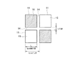
このときのセル開口径Lは、図2に示すように、セルピッチからリブ厚さ(セル壁14の厚さ)を差し引いて求めることができるもので、セル壁14で仕切られたセル11の一辺の長さを示している。
The cell opening diameter L at this time can be obtained by subtracting the rib thickness (thickness of the cell wall 14) from the cell pitch as shown in FIG. 2, and one side of the
図1は、このような構造のハニカム構造体10を部分的に示すものであり、排ガスの入口側の端面10aにおいて充填材16が長くなっており、これにより充填材16によって形成される目封じ深さDがセル開口径Lの3.4〜8.5倍となっている。なお、排ガスGの出口側の端面10bにおいては、従来と同様な目封じ深さdとするものである。
FIG. 1 partially shows a
入口側の端面10aにおける目封じ深さDは、深くするほどセル壁14の自由部分(濾過部分)が短くなるため、Oil−Ashが堆積できる面積(排ガス流が通過する面積)が減少するため、すすが堆積していないときでも圧力損失が上昇する。
As the plugging depth D in the
図3は、セル開口径に対する目封じ深さの比率を変化させた場合における圧力損失の割合を示すものであり、縦軸が、すす10g/L堆積時の圧損を測定し、そのときの従来に対する圧損上昇割合を示しており、横軸が、セル開口径に対する目封じ深さの比率を示している。目封じ深さ/セル開口径が9.0のときには圧力損失が従来に比べて10%上昇する。このような圧力損失の上昇は、排ガスG中のパティキュレートの捕捉効率が低下する。このため、この実施形態では、目封じ深さDの上限値はセル開口径Lの8.5倍とするものである。 FIG. 3 shows the ratio of pressure loss when the ratio of the plugging depth to the cell opening diameter is changed. The vertical axis measures the pressure loss when soot is deposited at 10 g / L. The pressure loss increase rate with respect to the cell opening diameter, and the horizontal axis indicates the ratio of the plugging depth to the cell opening diameter. When the plugging depth / cell opening diameter is 9.0, the pressure loss increases by 10% compared to the conventional case. Such an increase in pressure loss reduces the efficiency of capturing particulates in the exhaust gas G. Therefore, in this embodiment, the upper limit value of the sealing depth D is 8.5 times the cell opening diameter L.
また、セル開口径Lに対する目封じ深さが3.4倍に達しない場合には、入口側の端面10aにおける排ガスの乱流の抑制効果が小さくなる。このため、実施形態では目封じ深さDの下限値Dをセル開口径Lの3.4倍とするものである。
Further, when the plugging depth with respect to the cell opening diameter L does not reach 3.4 times, the effect of suppressing the turbulent flow of the exhaust gas at the
図4の特性曲線Bは、以上のように設定した実施形態によってOil−Ashの堆積厚さを測定した結果を示す。約10万キロ走行(相当)の後における入口側の端面10a付近のOil−Ashの堆積量が0.18mm(厚さ)となっており、出口側の端面10bの堆積量(0.15mm(厚さ))の1.2倍程度であり、略同等となっている。従って、流通孔15内においては、セル壁14にOil−Ashが略均一に堆積した状態となっており、流通孔15内で排ガスが滞留することなく円滑に流動することができ、圧力損失の低減を防止することが可能となっている。
The characteristic curve B in FIG. 4 shows the result of measuring the oil-ash deposition thickness according to the embodiment set as described above. The amount of oil-ash deposited in the vicinity of the
また、この実施形態におけるOil−Ashの堆積量に対する圧力損失(圧損)は、図5の特性曲線Bに示すように、Oil−Ashの堆積量が増加してもなだらかに上昇するだけとなっている。これによって、ハニカム構造体10の寿命を増大させることができる。
Further, the pressure loss (pressure loss) with respect to the amount of Oil-Ash deposition in this embodiment only increases gently even when the amount of Oil-Ash deposition increases, as shown by the characteristic curve B in FIG. Yes. Thereby, the lifetime of the
さらに好ましくは、入口側目封じは、一体型ハニカム構造体10の中央部分から外周部分に向かうにつれて深くなるように形成される。接合型ハニカム構造体10の場合には、複数のセグメント13の各々の入口側目封じは、接合型ハニカム構造体10の中央部分から外周部分に向かうにつれて深くなるように形成される。
More preferably, the inlet-side plug is formed so as to become deeper from the central portion of the
ハニカム構造体10の外周部分は、その中央部分に比べて排ガスの流速が小さいため、外周部分では、Oil−Ashが堆積し易い環境となっている。
Since the flow rate of exhaust gas is smaller in the outer peripheral portion of the
この構成は、一体型(または接合型)ハニカム構造体10の外周部分がその中央部分に比べて排ガスGの流速が小さいことに対応させたものであり、ハニカム構造体10の外周部分の入口側目封じの深さDを、中央部分のそれよりも深くすることにより、セルの長さ方向と直交するハニカム構造体10の断面内のOil−Ashの堆積分布を略均一にすることができるので、外周部分でのOil−Ashの堆積量が早期に限界量となることを防止することができる。
This configuration corresponds to the fact that the outer peripheral portion of the integrated (or bonded)
さらに好ましくは、一体型ハニカム構造体10では、外周部分の入口側目封じは、中央部分の入口側目封じの平均深さの1.05〜10.0倍の平均深さになるように形成され、接合型ハニカム構造体10では、接合型ハニカム構造体10の最外周部分を構成するセグメントの入口側目封じが、接合型ハニカム構造体の中央部分を構成するセグメントの入口側目封じの平均目封じ深さの1.05〜5.0倍、より好ましくは1.05〜3.0倍になる平均目封じ深さになるように形成される。
More preferably, in the
最外周部分の目封じ深さが、中央部分のそれに比べて、1.05倍以下であると、Oil−Ashは外周側に多く堆積するようになり、スートが中心部に多く堆積するようになる。このためスート再生時に中心側の方が外周側に比べ、スート燃焼による発熱が大きくなり、中心側と外周側での温度差が大きくなる。この温度差が非常に大きい場合は、その温度差により熱衝撃でクラックが発生する時がある。 When the plugging depth of the outermost peripheral part is 1.05 times or less than that of the central part, Oil-Ash is deposited more on the outer peripheral side, so that more soot is deposited on the central part. Become. For this reason, at the time of soot regeneration, heat generation due to soot combustion becomes larger on the center side than on the outer periphery side, and the temperature difference between the center side and the outer periphery side becomes larger. When this temperature difference is very large, cracks may occur due to thermal shock due to the temperature difference.
一方、外周の目封じ深さが中心部の目封じ深さに比べ、3.0倍以上、さらには5.0倍以上であると、外周側の目封じが深くなった分、ガス通過セルの面積が小さくなることで、圧損が上昇する。 On the other hand, if the outer peripheral sealing depth is 3.0 times or more, and further 5.0 times or more compared to the central sealing depth, the gas passing cell is increased by the amount of the outer peripheral sealing. The pressure loss increases by reducing the area of.
さらに好ましくは、接合型ハニカム構造体10では、各セグメント内の入口側目封じは、セグメントの中央部分から外周部分に向かうにつれて深くなるように形成される。
More preferably, in the bonded
この構成によれば、セルの長さ方向と直交するセグメントの断面内のOil−Ashの堆積分布を、各セグメント内で略均一にすることができ、総じてセルの長さ方向と直交するハニカム構造体10の断面内のOil−Ashの堆積分布をより確実に均一にすることができる。
According to this configuration, the oil-ash deposition distribution in the cross section of the segment orthogonal to the cell length direction can be made substantially uniform in each segment, and the honeycomb structure is generally orthogonal to the cell length direction. The oil-ash deposition distribution in the cross section of the
さらに好ましくは、接合型ハニカム構造体10では、各セグメント内の外周部分の入口側目封じは、セグメントの中央部分の入口側目封じの平均目封じ深さの1.05〜3.0倍、より好ましくは1.05〜2.0倍の平均目封じ深さになるように形成される。
More preferably, in the bonded
接合型ハニカム構造体の場合は、各セグメントを介する接合部にはガスが通過しないため、各セグメントの接合部に隣接するセルは各セグメント中央部に比べ、ガス流入速度が遅くなっている。すなわち、各セグメントにおいて一体型と同様なガス流入速度分布が形成されている。 In the case of the bonded honeycomb structure, since gas does not pass through the bonded portion through each segment, the gas inflow rate is slower in the cells adjacent to the bonded portion of each segment than in the central portion of each segment. That is, a gas inflow velocity distribution similar to that of the integrated type is formed in each segment.
このため、各セグメントの外周部分の目封じ深さが中央部分の1.05倍以下であると、各セグメントの外周部分にAshが堆積しやすくなり、一体型と同様、外周部分と中央部分との温度差が大きくなる事で、セグメント内にクラックが生じる可能性がある。 For this reason, when the plugging depth of the outer peripheral portion of each segment is 1.05 times or less of the central portion, Ash is likely to be deposited on the outer peripheral portion of each segment. As the temperature difference increases, cracks may occur in the segment.
一方、各セグメントの外周部分の目封じ深さが中央部分の2.0倍、さらには3.0倍以上であると、一体型と同様、外周部分の目封じ深さが深くなった分、ガス通過セルの面積が小さくなることで、圧損が大きく上昇してしまう。 On the other hand, if the sealing depth of the outer peripheral part of each segment is 2.0 times that of the central part, and further 3.0 times or more, as with the integrated type, By reducing the area of the gas passage cell, the pressure loss increases significantly.
この構成によれば、セルの長さ方向と直交するセグメントの断面内のOil−Ashの堆積分布をより確実に均一にすることができる。 According to this configuration, the oil-ash deposition distribution in the cross section of the segment orthogonal to the cell length direction can be made more reliable and uniform.
次に、本発明の実施例を説明するが、本発明は以下の実施例に限定されることなく本発明の主旨の範囲内で種々変形が可能である。例えば、セルを円形等の異なった断面としても良い。 Next, examples of the present invention will be described, but the present invention is not limited to the following examples, and various modifications can be made within the scope of the gist of the present invention. For example, the cells may have different cross sections such as a circle.
(実施例1〜4,比較例1)
セル密度46.5セル/cm2、セル壁(リブ厚)の厚さ0.3mm、□35.4mmのセグメントを16本積層し、直径143.8mm、軸方向長さ152.4mm、容積2.5リットルの円筒形の接合型ハニカム構造体を作製した。Examples 1 to 4 and Comparative Example 1
16 segments with a cell density of 46.5 cells / cm 2 , a cell wall (rib thickness) thickness of 0.3 mm, and □ 35.4 mm were laminated, a diameter of 143.8 mm, an axial length of 152.4 mm, and a volume of 2 A 5-liter cylindrical bonded honeycomb structure was produced.
そしてこの接合型ハニカム構造体を次のように目封じを施すことによって供試用セラミックフイルタとしての比較例1および実施例1〜3を作製した。このとき出口側目封じは、各供試用セラミックフイルタ共同一深さに形成した。 The bonded honeycomb structure was sealed as follows to produce Comparative Example 1 and Examples 1 to 3 as test ceramic filters. At this time, the outlet side seal was formed at the same depth in each ceramic filter for test.
比較例1:入口側目封じ深さDをセル開口径Lの3倍(D=3L)に形成した。 Comparative Example 1: The inlet side plugging depth D was formed to be 3 times the cell opening diameter L (D = 3L).
実施例1:入口側目封じ深さDをセル開口径Lの6倍(D=6L)に形成した。 Example 1: The inlet-side plugging depth D was formed to be 6 times the cell opening diameter L (D = 6L).
実施例2:入口側目封じ深さDをセル開口径Lの8倍(D=8L)に形成した。 Example 2: The inlet side plugging depth D was formed to be eight times the cell opening diameter L (D = 8L).
実施例3:入口側目封じ深さDをセル開口径Lの10倍(D=10L)に形成した。 Example 3 The inlet-side plugging depth D was formed 10 times the cell opening diameter L (D = 10 L).
実施例4:図7に示すように、中央部分の4個のセグメントC1〜C4の入口側目封じ深さDをセル開口径Lの5倍(D=5L)に形成すると共に、外周部分の12個のセグメントC5〜C16の入口側目封じ深さDをセル開口径Lの7倍(D=7L)に形成した。 Example 4: As shown in FIG. 7, the inlet side plugging depth D of the four segments C1 to C4 in the central portion is formed to be 5 times the cell opening diameter L (D = 5L), and the outer peripheral portion The inlet side plugging depth D of the 12 segments C5 to C16 was formed to be 7 times the cell opening diameter L (D = 7L).
以上の比較例1および実施例1〜4の供試用セラミックフイルタを、排気量2.0リットルのディーゼルエンジンにおける排気系に設置し、排ガス温度を一定の300℃に保ち、5時間おきに排気温度が600℃の状態を15分間継続することにより供試用セラミックフイルタの再生を行った。この再生によりスートが完全になくなり、Oil−Ashだけが堆積した状態となった。このときの供試用セラミックフイルタの重量を測定してOil−Ashの堆積量を測定した。この試験をOil−Ashが150g堆積するまで行った。 The test ceramic filters of Comparative Example 1 and Examples 1 to 4 are installed in the exhaust system of a diesel engine with a displacement of 2.0 liters, the exhaust gas temperature is kept at a constant 300 ° C., and the exhaust temperature is changed every 5 hours. Was maintained at 600 ° C. for 15 minutes to regenerate the test ceramic filter. This regeneration completely eliminated soot, and only Oil-Ash was deposited. The weight of the test ceramic filter at this time was measured, and the amount of Oil-Ash deposited was measured. This test was conducted until 150 g of Oil-Ash was deposited.
図6は、Oil−Ashが150g堆積するまでの圧損変化を示しており、表1は、Oil−Ashが150g堆積したときにおける各実施例1〜4の圧力損失の比較であり、比較例1を1として比較した場合の数値を示している。

図6から明らかなように、比較例1は圧力損失が急上昇しているのに対し、実施例1〜4では圧力損失がなだらかに上昇している。 As is clear from FIG. 6, the pressure loss in Comparative Example 1 increases sharply, whereas in Examples 1 to 4, the pressure loss increases gently.
また、表1から明らかなように、実施例1〜4は1未満の数値を示しており、これにより圧損上昇の抑制効果が認められる。 Moreover, as is clear from Table 1, Examples 1 to 4 show numerical values less than 1, thereby confirming the effect of suppressing an increase in pressure loss.
さらに実施例4は、ハニカム構造体の外周側が中心側に比べて排ガスの流速が小さいことに対応させたものであり、ハニカム構造体の外周側の目封じ深さを中心側のそれよりも大きくしている。これにより、図6および表1から明らかなように、Oil−Ashの分布を均一にすることができ、外周側でのOil−Ashの堆積量が早期に限界量となることを防止することができた。 Furthermore, in Example 4, the outer peripheral side of the honeycomb structure is made to correspond to the lower flow rate of the exhaust gas than the central side, and the plugging depth on the outer peripheral side of the honeycomb structure is larger than that on the central side. is doing. As can be seen from FIG. 6 and Table 1, this makes it possible to make the Oil-Ash distribution uniform, and prevent the Oil-Ash deposition amount on the outer peripheral side from becoming an early limit amount. did it.
(実施例5〜11,比較例2〜3)
供試用セラミックフイルタ:143.8mmφ×152.4mmL、12mil/300cpsi
各サンプルの目封じデータは表2に示し、その模式図を図8〜図11に示す。図中、符号Aは入口側目封じ、符号Bは出口側目封じをそれぞれ示す。各サンプルの出口側目封じ深さは5mmで一定である。
Ceramic filter for test: 143.8 mmφ × 152.4 mmL, 12 mil / 300 cpsi
The sealing data of each sample is shown in Table 2, and the schematic diagram is shown in FIGS. In the figure, symbol A indicates an inlet side seal, and symbol B indicates an outlet side seal. The outlet sealing depth of each sample is constant at 5 mm.
比較例2:一体型ハニカム構造体からなるもので、入口側と出口側の目封じ深さは、共に5mmで同一であり、図8に示す。 Comparative Example 2: It is made of an integral honeycomb structure, and the plugging depths at the inlet side and the outlet side are the same at 5 mm, as shown in FIG.
実施例5:一体型ハニカム構造体からなるもので、入口側目封じ深さ7mmであり、図8に示す。 Example 5: It is made of an integral honeycomb structure and has an inlet-side plugging depth of 7 mm, as shown in FIG.
実施例6:一体型ハニカム構造体からなるもので、入口側目封じ深さ9mmであり、図8に示す。 Example 6: It is made of an integral honeycomb structure and has an inlet side plugging depth of 9 mm, as shown in FIG.
比較例3:一体型ハニカム構造体からなるもので、入口側目封じ深さをセル開口径の15.5倍にしたもので、図8に示す。 Comparative Example 3: This was made of an integral honeycomb structure, and the inlet side plugging depth was 15.5 times the cell opening diameter, and is shown in FIG.
実施例7:一体型ハニカム構造体からなるもので、入口側目封じ深さを、中央部分5mm、外周部分9mmしたもので、図9に示す。 Example 7: It is composed of an integral honeycomb structure, and the inlet side plugging depth is 5 mm at the center and 9 mm at the outer periphery, as shown in FIG.
実施例8:□35mmセグメントを複数接合した接合型ハニカム構造体からなるもので、図10に示す。 Example 8: This is composed of a joined honeycomb structure in which a plurality of □ 35 mm segments are joined, and is shown in FIG.
実施例9:□35mmセグメントを複数接合した接合型ハニカム構造体からなるもので、図10に示す。 Example 9: This is composed of a joined honeycomb structure in which a plurality of □ 35 mm segments are joined, and is shown in FIG.
実施例10:□35mmセグメントを複数接合した接合型ハニカム構造体からなるもので、入口側目封じ深さは各セグメント内で分布したものとなっており、図11に示す。 Example 10: This is composed of a joined type honeycomb structure in which a plurality of □ 35 mm segments are joined, and the inlet side plugging depth is distributed in each segment, as shown in FIG.
実施例11:□35mmセグメントを複数接合した接合型ハニカム構造体からなるもので、入口側目封じ深さは各セグメント内で分布したものとなっており、図11に示す。 Example 11: This is composed of a joined honeycomb structure in which a plurality of □ 35 mm segments are joined, and the inlet side plugging depth is distributed within each segment, as shown in FIG.
試験条件:比較例2,3および実施例5〜11の供試用セラミックフイルタを、排気量2.0リットルのディーゼルエンジンにおける排気系に設置し、排ガス温度を一定の250℃に保ち、5時間おきに排気温度が600℃の状態を10分間継続することにより供試用セラミックフイルタの再生を行った。この繰り返しをOil−Ashが200g堆積するまで行った。その後、供試用セラミックフイルタを電気炉にて600℃で3時間加熱して完全にすすを飛ばし、このものを圧損測定に供した。 Test conditions: The test ceramic filters of Comparative Examples 2 and 3 and Examples 5 to 11 were installed in an exhaust system of a diesel engine with a displacement of 2.0 liters, and the exhaust gas temperature was kept at a constant 250 ° C. every 5 hours. Then, the test ceramic filter was regenerated by continuing the state where the exhaust temperature was 600 ° C. for 10 minutes. This was repeated until 200 g of Oil-Ash was deposited. Thereafter, the test ceramic filter was heated in an electric furnace at 600 ° C. for 3 hours to completely remove soot, and this was subjected to pressure loss measurement.
圧損測定は、風洞にて25℃、1〜9Nm3/minの条件下で行っい、得られた9Nm3/minの圧損値を比較データとした。The pressure loss measurement was performed in a wind tunnel under conditions of 25 ° C. and 1 to 9 Nm 3 / min, and the obtained pressure loss value of 9 Nm 3 / min was used as comparison data.
結果:表3は、9Nm3/minの圧損値、および比較例2の圧損値を1としたときの圧損比を示しており、図12は、9Nm3/minの圧損値を棒グラフで示したものである。
表3および図12から明らかなように、比較例2、3は22.0以上の圧損値を示すが、実施例5〜11は、いずれも20以下の圧損値、および1未満の圧損比を示しており、圧損上昇の抑制効果を認めることができる。 As is apparent from Table 3 and FIG. 12, Comparative Examples 2 and 3 show a pressure loss value of 22.0 or more, but Examples 5 to 11 all have a pressure loss value of 20 or less and a pressure loss ratio of less than 1. It can be seen that the effect of suppressing the increase in pressure loss can be recognized.
本発明のセラミックフィルタは、DPF等のディーゼルエンジンの排ガスを浄化するために好ましく使用できる。 The ceramic filter of the present invention can be preferably used for purifying exhaust gas from diesel engines such as DPF.
Claims (9)
前記入口側目封じは、出口側目封じよりも深くなるように形成されていることを特徴とするセラミックフィルタ。A ceramic filter formed of an integrated honeycomb structure in which a plurality of cells penetrating in the longitudinal direction are formed as an integrated product, and an end surface on the inlet side and an end surface on the outlet side of the exhaust gas in the cell are alternately sealed. There,
The ceramic filter according to claim 1, wherein the inlet side seal is formed deeper than the outlet side seal.
前記入口側目封じは、出口側目封じよりも深くなるように形成されていることを特徴とするセラミックフィルタ。It is formed by joining a plurality of segments each provided with a large number of cells penetrating in the longitudinal direction, and is formed of a joined honeycomb structure in which end faces on the exhaust gas inlet side and end faces on the outlet side of the cells are alternately sealed. A ceramic filter,
The ceramic filter according to claim 1, wherein the inlet side seal is formed deeper than the outlet side seal.
Applications Claiming Priority (3)
| Application Number | Priority Date | Filing Date | Title |
|---|---|---|---|
| JP2004085374 | 2004-03-23 | ||
| JP2004085374 | 2004-03-23 | ||
| PCT/JP2005/005228 WO2005089902A1 (en) | 2004-03-23 | 2005-03-23 | Ceramic filter |
Publications (2)
| Publication Number | Publication Date |
|---|---|
| JPWO2005089902A1 JPWO2005089902A1 (en) | 2008-01-31 |
| JP4567674B2 true JP4567674B2 (en) | 2010-10-20 |
Family
ID=34993481
Family Applications (1)
| Application Number | Title | Priority Date | Filing Date |
|---|---|---|---|
| JP2006511300A Expired - Lifetime JP4567674B2 (en) | 2004-03-23 | 2005-03-23 | Ceramic filter |
Country Status (5)
| Country | Link |
|---|---|
| US (1) | US7547342B2 (en) |
| EP (1) | EP1733777B1 (en) |
| JP (1) | JP4567674B2 (en) |
| KR (1) | KR100766357B1 (en) |
| WO (1) | WO2005089902A1 (en) |
Cited By (5)
| Publication number | Priority date | Publication date | Assignee | Title |
|---|---|---|---|---|
| DE102017002528A1 (en) | 2016-03-23 | 2017-09-28 | Ngk Insulators, Ltd. | honeycombs |
| DE102017002529A1 (en) | 2016-03-23 | 2017-09-28 | Ngk Insulators, Ltd. | honeycombs |
| DE102018204933A1 (en) | 2017-03-30 | 2018-10-04 | Ngk Insulators, Ltd. | honeycombs |
| DE102018204932A1 (en) | 2017-03-30 | 2018-10-18 | Ngk Insulators, Ltd. | honeycombs |
| US10918988B2 (en) | 2018-09-27 | 2021-02-16 | Ngk Insulators, Ltd. | Honeycomb filter |
Families Citing this family (11)
| Publication number | Priority date | Publication date | Assignee | Title |
|---|---|---|---|---|
| WO2008096503A1 (en) * | 2007-02-02 | 2008-08-14 | Ngk Insulators, Ltd. | Honeycomb structure |
| EP2127719B1 (en) | 2007-02-02 | 2014-09-10 | NGK Insulators, Ltd. | Honeycomb structure |
| US7931715B2 (en) * | 2007-02-12 | 2011-04-26 | Gm Global Technology Operations, Inc. | DPF heater attachment mechanisms |
| US7862635B2 (en) * | 2007-02-12 | 2011-01-04 | Gm Global Technology Operations, Inc. | Shielded regeneration heating element for a particulate filter |
| JP5456268B2 (en) * | 2008-03-28 | 2014-03-26 | 日本碍子株式会社 | Honeycomb structure |
| US8945698B2 (en) * | 2009-09-24 | 2015-02-03 | Ngk Insulators, Ltd. | Honeycomb structure and method for manufacturing the same |
| US20110076443A1 (en) * | 2009-09-30 | 2011-03-31 | Ngk Insulators, Ltd. | Honeycomb structure and method for manufacturing the same |
| JP6060074B2 (en) * | 2011-04-25 | 2017-01-11 | 日本碍子株式会社 | Cleaning method of ceramic filter |
| JP2015009205A (en) * | 2013-06-28 | 2015-01-19 | 京セラ株式会社 | Honeycomb structure body and gas treatment device using the same |
| JP6174517B2 (en) * | 2014-05-02 | 2017-08-02 | 日本碍子株式会社 | Honeycomb structure |
| JP7217191B2 (en) * | 2019-03-29 | 2023-02-02 | 日本碍子株式会社 | honeycomb filter |
Citations (3)
| Publication number | Priority date | Publication date | Assignee | Title |
|---|---|---|---|---|
| JP2003254034A (en) * | 2002-02-26 | 2003-09-10 | Ngk Insulators Ltd | Honeycomb filter |
| JP2003269132A (en) * | 2002-03-13 | 2003-09-25 | Ngk Insulators Ltd | Exhaust emission control filter |
| JP2004113930A (en) * | 2002-09-26 | 2004-04-15 | Hitachi Metals Ltd | Method and apparatus for manufacturing ceramic honeycomb filter |
Family Cites Families (17)
| Publication number | Priority date | Publication date | Assignee | Title |
|---|---|---|---|---|
| JPS5928010A (en) * | 1982-08-05 | 1984-02-14 | Nippon Denso Co Ltd | Structure to purify exhaust gas |
| US4509966A (en) | 1983-05-18 | 1985-04-09 | General Motors Corporation | Wall-flow monolith filter with porous plugs |
| JPS6110917U (en) | 1984-06-25 | 1986-01-22 | マツダ株式会社 | Engine exhaust gas purification filter |
| DE3444472C1 (en) * | 1984-12-06 | 1986-02-13 | Daimler-Benz Ag, 7000 Stuttgart | Exhaust filter for diesel engines |
| JPH0631133Y2 (en) * | 1988-10-31 | 1994-08-22 | いすゞ自動車株式会社 | Exhaust gas purification filter |
| JPH0710024Y2 (en) | 1989-02-27 | 1995-03-08 | 日産ディーゼル工業株式会社 | Structure of the particulate filter |
| JP2807370B2 (en) | 1992-03-23 | 1998-10-08 | 日本碍子株式会社 | Inspection method and apparatus for pressure loss during regeneration of exhaust gas purifying honeycomb structure |
| JP3012167B2 (en) * | 1995-04-12 | 2000-02-21 | 日本碍子株式会社 | Exhaust gas purification filter and exhaust gas purification device using the same |
| JP2001269522A (en) * | 2000-03-27 | 2001-10-02 | Ngk Insulators Ltd | Filter made of porous ceramics sintered body |
| US6508852B1 (en) * | 2000-10-13 | 2003-01-21 | Corning Incorporated | Honeycomb particulate filters |
| JP2002309922A (en) | 2001-04-16 | 2002-10-23 | Denso Corp | Exhaust emission purifier |
| ATE498598T1 (en) | 2001-04-23 | 2011-03-15 | Dow Global Technologies Inc | METHOD FOR PRODUCING A MONOLITHIC WALL FLOW FILTER |
| US7107763B2 (en) * | 2002-03-29 | 2006-09-19 | Hitachi Metals, Ltd. | Ceramic honeycomb filter and exhaust gas-cleaning method |
| JP3872384B2 (en) * | 2002-06-13 | 2007-01-24 | トヨタ自動車株式会社 | Exhaust gas purification filter catalyst |
| US7090714B2 (en) * | 2002-06-17 | 2006-08-15 | Hitachi Metals, Ltd. | Ceramic honeycomb filter |
| JP3874270B2 (en) | 2002-09-13 | 2007-01-31 | トヨタ自動車株式会社 | Exhaust gas purification filter catalyst and method for producing the same |
| JP4653387B2 (en) | 2003-04-21 | 2011-03-16 | 日本碍子株式会社 | Honeycomb structure and exhaust fluid purification system |
-
2005
- 2005-03-23 EP EP05726963.1A patent/EP1733777B1/en not_active Expired - Lifetime
- 2005-03-23 JP JP2006511300A patent/JP4567674B2/en not_active Expired - Lifetime
- 2005-03-23 US US10/592,804 patent/US7547342B2/en active Active
- 2005-03-23 KR KR1020067021804A patent/KR100766357B1/en active IP Right Grant
- 2005-03-23 WO PCT/JP2005/005228 patent/WO2005089902A1/en active Application Filing
Patent Citations (3)
| Publication number | Priority date | Publication date | Assignee | Title |
|---|---|---|---|---|
| JP2003254034A (en) * | 2002-02-26 | 2003-09-10 | Ngk Insulators Ltd | Honeycomb filter |
| JP2003269132A (en) * | 2002-03-13 | 2003-09-25 | Ngk Insulators Ltd | Exhaust emission control filter |
| JP2004113930A (en) * | 2002-09-26 | 2004-04-15 | Hitachi Metals Ltd | Method and apparatus for manufacturing ceramic honeycomb filter |
Cited By (9)
| Publication number | Priority date | Publication date | Assignee | Title |
|---|---|---|---|---|
| DE102017002528A1 (en) | 2016-03-23 | 2017-09-28 | Ngk Insulators, Ltd. | honeycombs |
| DE102017002529A1 (en) | 2016-03-23 | 2017-09-28 | Ngk Insulators, Ltd. | honeycombs |
| US10478766B2 (en) | 2016-03-23 | 2019-11-19 | Ngk Insulators, Ltd. | Honeycomb filter |
| US10525394B2 (en) | 2016-03-23 | 2020-01-07 | Ngk Insulators, Ltd. | Honeycomb filter |
| DE102018204933A1 (en) | 2017-03-30 | 2018-10-04 | Ngk Insulators, Ltd. | honeycombs |
| DE102018204932A1 (en) | 2017-03-30 | 2018-10-18 | Ngk Insulators, Ltd. | honeycombs |
| US11058983B2 (en) | 2017-03-30 | 2021-07-13 | Ngk Insulators, Ltd. | Honeycomb filter |
| US11065571B2 (en) | 2017-03-30 | 2021-07-20 | Ngk Insulators, Ltd. | Honeycomb filter |
| US10918988B2 (en) | 2018-09-27 | 2021-02-16 | Ngk Insulators, Ltd. | Honeycomb filter |
Also Published As
| Publication number | Publication date |
|---|---|
| KR100766357B1 (en) | 2007-10-15 |
| EP1733777A1 (en) | 2006-12-20 |
| EP1733777B1 (en) | 2014-10-22 |
| WO2005089902A1 (en) | 2005-09-29 |
| US7547342B2 (en) | 2009-06-16 |
| KR20070004875A (en) | 2007-01-09 |
| EP1733777A4 (en) | 2007-10-17 |
| JPWO2005089902A1 (en) | 2008-01-31 |
| US20070240396A1 (en) | 2007-10-18 |
Similar Documents
| Publication | Publication Date | Title |
|---|---|---|
| JP4567674B2 (en) | Ceramic filter | |
| CN101449034B (en) | Filter device, especially for an exhaust system of an internal combustion engine | |
| JP6140509B2 (en) | Wall flow type exhaust gas purification filter | |
| US8012234B2 (en) | Honeycomb structural body | |
| KR100595407B1 (en) | Particulate matter reducing apparatus | |
| JP3983117B2 (en) | Honeycomb structure and manufacturing method thereof | |
| EP1598534A2 (en) | Honeycomb filter and exhaust gas purification system | |
| JP6279368B2 (en) | Exhaust gas purification device | |
| JP2010511126A (en) | Partial wall flow filter and diesel exhaust system and method | |
| KR100747088B1 (en) | Catalytic DPF for Diesel Engine Soot Filters with Improved Thermal Durability | |
| JP6246683B2 (en) | Honeycomb filter | |
| WO2012046484A1 (en) | Exhaust gas purification device | |
| JP5218056B2 (en) | Ceramic honeycomb filter | |
| US8092565B2 (en) | Particulate filter | |
| JP4640987B2 (en) | Ceramic filter | |
| JP6259334B2 (en) | Honeycomb structure | |
| JP2004154647A (en) | Ceramics honeycomb filter | |
| JP2000042420A (en) | Exhaust gas purifier | |
| JP6174517B2 (en) | Honeycomb structure | |
| JP2011102557A (en) | Diesel particulate filter | |
| JP2017170323A (en) | Honeycomb filter | |
| JP2004108202A (en) | Particulate filter | |
| JP6887302B2 (en) | Honeycomb filter | |
| JP3943891B2 (en) | Particulate filter | |
| JP2011041933A (en) | Exhaust cleaning filter |
Legal Events
| Date | Code | Title | Description |
|---|---|---|---|
| A621 | Written request for application examination |
Free format text: JAPANESE INTERMEDIATE CODE: A621 Effective date: 20071114 |
|
| TRDD | Decision of grant or rejection written | ||
| A01 | Written decision to grant a patent or to grant a registration (utility model) |
Free format text: JAPANESE INTERMEDIATE CODE: A01 Effective date: 20100803 |
|
| A01 | Written decision to grant a patent or to grant a registration (utility model) |
Free format text: JAPANESE INTERMEDIATE CODE: A01 |
|
| A61 | First payment of annual fees (during grant procedure) |
Free format text: JAPANESE INTERMEDIATE CODE: A61 Effective date: 20100805 |
|
| R150 | Certificate of patent or registration of utility model |
Ref document number: 4567674 Country of ref document: JP Free format text: JAPANESE INTERMEDIATE CODE: R150 Free format text: JAPANESE INTERMEDIATE CODE: R150 |
|
| FPAY | Renewal fee payment (event date is renewal date of database) |
Free format text: PAYMENT UNTIL: 20130813 Year of fee payment: 3 |