JP4552047B2 - Interlocking and non-interlocking mechanism of reclining wheelchair leg support frame - Google Patents
Interlocking and non-interlocking mechanism of reclining wheelchair leg support frame Download PDFInfo
- Publication number
- JP4552047B2 JP4552047B2 JP2003414021A JP2003414021A JP4552047B2 JP 4552047 B2 JP4552047 B2 JP 4552047B2 JP 2003414021 A JP2003414021 A JP 2003414021A JP 2003414021 A JP2003414021 A JP 2003414021A JP 4552047 B2 JP4552047 B2 JP 4552047B2
- Authority
- JP
- Japan
- Prior art keywords
- support frame
- leg support
- reclining
- leg
- frame
- Prior art date
- Legal status (The legal status is an assumption and is not a legal conclusion. Google has not performed a legal analysis and makes no representation as to the accuracy of the status listed.)
- Expired - Fee Related
Links
- 230000007246 mechanism Effects 0.000 title claims description 27
- 230000037431 insertion Effects 0.000 claims description 8
- 238000003780 insertion Methods 0.000 claims description 8
- 230000006835 compression Effects 0.000 claims description 6
- 238000007906 compression Methods 0.000 claims description 6
- 239000000470 constituent Substances 0.000 claims description 2
- 230000008602 contraction Effects 0.000 description 3
- 230000002265 prevention Effects 0.000 description 2
- 230000005484 gravity Effects 0.000 description 1
- 230000002093 peripheral effect Effects 0.000 description 1
- 238000004904 shortening Methods 0.000 description 1
Images


Landscapes
- Chairs For Special Purposes, Such As Reclining Chairs (AREA)
Description
本発明は、身体障害者や高齢者等が使用するリクライニング可能な車椅子に関するものである。 The present invention relates to a reclining wheelchair used by a physically handicapped person or an elderly person.
従来から、フレーム本体の上面に座席を設け、前記座席の後側に起立状態から後方へ傾倒可能な背部支持枠を設け、一方、前記座席の前側に上下回動可能な脚部支持枠を設け、前記背部支持枠をリクライニングさせたときに、脚部支持枠を上方回動させて使用者の脚側を支持することができるリクライニング可能な車椅子が種々提案されている。 Conventionally, a seat is provided on the upper surface of the frame body, a back support frame that can tilt backward from the standing state is provided on the rear side of the seat, and a leg support frame that can be turned up and down is provided on the front side of the seat. Various reclining wheelchairs have been proposed in which when the back support frame is reclined, the leg support frame can be turned upward to support the leg side of the user.
さらに、前記背部支持枠の下端部と脚部支持枠とをロッドで連結して四節リンク機構を構成し、背部支持枠のリクライニングに連動して脚部支持枠が上動するように設けたものもある。
しかしながら、上記従来のリクライニング可能な車椅子は、背部支持枠と脚部支持枠とが連動構成されているから、使用者を椅子掛け状態から仰臥状態にワンタッチで姿勢変更できる利便性を有する反面、脚を伸ばした状態で着座することができないという問題点があった。
Further, the lower end portion of the back support frame and the leg support frame are connected by a rod to form a four-bar linkage mechanism, and the leg support frame is provided to move up in conjunction with the reclining of the back support frame. There are also things.
However, the conventional reclinable wheelchair has a back support frame and a leg support frame that are linked to each other. There was a problem of being unable to sit down with the arm extended.
そこで、これを解決するために、上面部に座席を備えるとともに左右一対の前輪と後輪を有するフレーム本体を設け、前記フレーム本体は、前側に上下方向回動自在な脚部支持枠を設けるとともに後側に適宜リクライニング可能な背部支持枠を設け、前記脚部支持枠はフレーム本体に対して段階的に角度変更可能に支持手段により支持し、当該支持手段と背部支持枠側とを伸長自在な連結ロッドにより連結してなり、前記背部支持枠を傾倒させると連結ロッドが軸方向に圧縮されて最短状態となるとともに支持手段を解除して、脚部支持枠が当該連結ロッドにより押し上げられて上方回動し、脚部支持枠側を上方回動させると連結ロッドが伸長して当該脚部支持枠が背部支持枠とは無関係に回動するとともに支持手段により支持される状態となるよう設けられてなることを特徴とするリクライニング可能な車椅子が提案されている。
このように構成されたリクライニング可能な車椅子は、背部支持枠のリクライニングに連動して脚部支持枠を上下回動させることができるとともに、リクライニング操作に関わらず、脚部支持枠を上方回動操作することが可能に構成されている。
しかしながら、背部支持枠をリクライニングさせた状態では、脚部支持枠が上方に回動された状態となっており、背部支持枠をリクライニングさせた状態で脚部支持枠を下げた状態に角度設定ができないという欠点があった。
The reclining wheelchair configured as described above can rotate the leg support frame up and down in conjunction with the reclining of the back support frame, and can rotate the leg support frame upward regardless of the reclining operation. It is configured to be able to.
However, when the back support frame is reclined, the leg support frame is turned upward, and the angle is set so that the leg support frame is lowered while the back support frame is reclined. There was a disadvantage that it was not possible.
そこで本発明は上記問題点に鑑み、脚部支持枠が背部支持枠のリクライニングに連動して上下に連動させることも、背部支持枠のリクライニング状態に関わらず前記脚部支持枠を単独で上下に回動させることも可能なリクライニング可能な車椅子を提供することを課題としている。 Therefore, in view of the above problems, the present invention can be configured such that the leg support frame is linked up and down in conjunction with the reclining of the back support frame. An object is to provide a reclining wheelchair that can be rotated.
請求項1の発明では、上面部を座席とすると共に左右一対の前輪(7),(7)と後輪(8),(8)を有するようにフレーム本体(1)を構成し、該フレーム本体(1)には前記座席の前方で上下回動自在となるよう脚部支持枠(29)を設けると共に前記座席の後方にリクライニング自在となるよう背部支持枠(11)を設け、前記脚部支持枠(29)は前記フレーム本体(1)との間に支持手段(34)を介在して前記座席に対して段階的に角度変更自在に支持するに、前記支持手段(34)は前記脚部支持枠(29)の裏側に上下回動可能に取り付けた支持プレート(37)と前記フレーム本体(1)に設けられる横方向の支軸(40)とからなり、前記支持プレート(37)の中央部には前記支軸(40)を挿通する通孔部(38)を形成すると共に当該通孔部(38)の上側には前記支軸(40)が係脱可能な凸状の複数の係合溝(38a),(38b),(38c)を一体的に形成し、前記支軸(40)が前記支持プレート(37)の自重による下方回動により何れかの係合溝(38a),(38b),(38c)に係合して前記脚部支持枠(29)を段階的に支持するよう構成し、当該支持手段(34)と前記背部支持枠(11)あるいはリクライニング操作により前後回動するリクライニング機構(13)の構成部材とを伸縮自在な状態と圧縮方向に対しては一定長で保持される状態とに切替自在に構成してなる連結ロッド(41)で連結するに、該連結ロッド(41)は外側パイプ(41b)に前記支持プレート(37)の取付部後方上部に連結した内側パイプ(41c)を挿通すると共に、該外側パイプ(41b)の後部に挿脱操作自在となるピン(43)を具備して構成したもので、該ピン(43)を抜いて前記連結ロッド(41)が伸縮自在な状態では前記背部支持枠(11)のリクライニング操作に係わらず、前記脚部支持枠(29)を上下に回動操作自在かつ前記支持手段(34)の支持プレート(37)が自重により下方回動することで段階的に保持できる一方、前記ピン(43)を挿通して前記連結ロッド(41)が圧縮方向に対して一定長で保持される状態ではリクライニング操作による前記背部支持枠(11)の上下回動に連動して前記連結ロッド(41)が前記支持手段(34)の支持プレート(37)を上方回動して前記脚部支持枠(29)の保持状態を解除して該脚部支持枠(29)が上下回動されその状態を保持すると共に、この保持状態から脚部支持枠(29)のみ上方側に回動操作でき前記支持手段(34)で保持されるよう構成したことを特徴とする。
請求項2の発明では、上記連結ロッド(41)を一定長で保持するためのピン(43)をスプリング(47)により前記外側パイプ(41b)内に挿通する方向に付勢すると共に、車椅子(K)のハンドル(12)または前記脚部支持枠(29)に取り付けるレバー部材(49)と前記ピン(43)をワイヤー部材(48)で連結してなる挿脱手段(44)を設けたことを特徴とする。
According to the first aspect of the present invention, the frame body (1) is configured so that the upper surface portion serves as a seat and has a pair of left and right front wheels (7), (7) and rear wheels (8), (8). The main body (1) is provided with a leg support frame (29) so as to be pivotable up and down in front of the seat, and is provided with a back support frame (11) so as to be reclining behind the seat. to stepwise angle change rotatably supported with respect to the support frame (29) is the seat interposed support means (34) between the frame body (1), said support means (34) is the leg A support plate (37) attached to the back side of the support frame (29) so as to be vertically rotatable and a lateral support shaft (40) provided on the frame body (1). A through hole portion (38) through which the support shaft (40) is inserted in the central portion. And a plurality of convex engaging grooves (38a), (38b), (38c) with which the support shaft (40) can be engaged and disengaged are integrally formed on the upper side of the through hole (38). The support shaft (40) is engaged with any of the engaging grooves (38a), (38b), (38c) by the downward rotation due to the weight of the support plate (37), and the leg support frame ( 29) is supported in a stepwise manner, and the support means (34) and the back support frame (11) or the constituent members of the reclining mechanism (13) rotated back and forth by a reclining operation can be expanded and contracted. The connecting rod (41) is connected to the outer pipe (41b) by connecting the connecting plate ( 41) so that it can be switched to a state where it is held at a fixed length with respect to the direction. inner pie coupled to the mounting portion upper rear of the With inserting the (41c), which was constructed by comprising a pin (43) to be detachably operation on the rear of the outer pipe (41b), the connecting rod by far the pin (43) (41) In a state in which the leg support frame can be extended and retracted, the leg support frame (29) can be rotated up and down regardless of the reclining operation of the back support frame (11), and the support plate (37) of the support means (34) is self-weighted. In the state where the pin (43) is inserted and the connecting rod (41) is held at a fixed length in the compression direction, the back support frame by the reclining operation can be held in a stepwise manner. In conjunction with the vertical rotation of (11), the connecting rod (41) rotates the support plate (37) of the support means (34) upward to release the holding state of the leg support frame (29). The leg support frame (29) is rotated up and down to hold the state, and only the leg support frame (29) can be rotated upward from this holding state and held by the support means (34). And
In the invention of
請求項1の発明では、フレーム本体の前後に背部支持枠と脚部支持枠を隣接配置し、座席部を形成している。そして、背部支持枠はフレーム本体に対してリクライニング可能に取り付けられている。また、脚部支持枠は上下に回動自在に取り付けられている。このように構成されたリクライニング可能な車椅子で、背部支持枠のリクライニング操作に連動して脚部支持枠を回動操作可能に構成しているので、このリクライニング可能な車椅子の操作が非常に至便である。また、脚部支持枠をリクライニングに連動して回動させるだけでなく、背部支持枠のリクライニングとは連動させることなく、背部支持枠単独で脚部支持枠の支持角度を操作可能に構成しているので、背部支持枠の角度及び脚部支持枠の角度を個別に調節できる。したがって、車椅子に乗っている方の好みに合わせた最適な状態とすることができ、快適に乗車することができる。
また、請求項2の発明では、支持手段をフレーム本体に設けた支軸と脚部支持枠に上下回動可能に取り付けた支持プレートからなり、支持プレートに設けた通孔部に支軸を係合して段階的に脚部支持枠を支持するよう構成している。そして、連結ロッドを伸縮自在な状態と、一定長で保持する状態とに切替えることができるように挿脱手段が構成されており、この連結ロッドを適宜切替えることで背部支持枠のリクライニング操作に連動して脚部支持枠を回動させたり、脚部支持枠単独で回動操作可能にすることができている。したがって、構成が非常に簡単であり、安価に提供することができる。
In the first aspect of the present invention, the back portion support frame and the leg portion support frame are disposed adjacent to each other before and after the frame body to form the seat portion. The back support frame is attached to the frame body so as to be reclining. Moreover, the leg part support frame is attached so that rotation up and down is possible. The reclining wheelchair configured in this way is configured so that the leg support frame can be rotated in conjunction with the reclining operation of the back support frame. is there. In addition to rotating the leg support frame in conjunction with the reclining, the support angle of the leg support frame can be operated by the back support frame alone without being interlocked with the reclining of the back support frame. Therefore, the angle of the back support frame and the angle of the leg support frame can be individually adjusted. Therefore, it is possible to achieve an optimum state according to the preference of the person riding in the wheelchair and to ride comfortably.
In the invention of
フレーム本体と、このフレーム本体の前後に隣接配置された背部支持枠及び脚部支持枠とからなる座席部を形成し、前記背部支持枠はフレーム本体に対してリクライニング可能に取り付けられるとともに、脚部支持枠は上下に回動自在に取り付けられてなるリクライニング可能な車椅子とする。さらに、背部支持枠のリクライニング操作に連動して脚部支持枠を上下に回動することができるとともに、背部支持枠のリクライニング状態に関わらず脚部支持枠を単独で上下に回動調節可能に構成してなる脚部支持枠の連動及び非連動機構を具備させる。 A seat portion is formed of a frame main body, and a back support frame and a leg support frame that are disposed adjacent to each other before and after the frame main body, and the back support frame is attached to the frame main body so as to be reclining, and the leg portion The support frame is a reclining wheelchair that is pivotably attached up and down. In addition, the leg support frame can be rotated up and down in conjunction with the reclining operation of the back support frame, and the leg support frame can be adjusted up and down independently regardless of the reclining state of the back support frame. An interlocking and non-interlocking mechanism for the leg support frame is provided.
以下、本発明の実施例について図面に基づき詳細に説明する。 Hereinafter, embodiments of the present invention will be described in detail with reference to the drawings.
まず、リクライニング可能な車椅子Kについて説明する。
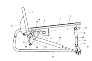
1はフレーム本体である。このフレーム本体1は、側面視が前方開口のコ字状に形成されたフレームパイプ2aの前端側を上下方向の縦パイプ2bで連結してなる一対の側部フレーム2,2を左右に略々座幅間隔に離間させて配設し、各縦パイプ2b,2bを横パイプ3,4で連結して一体的に構成したものである。また、前記フレームパイプ2aの上側水平部の前後中間部には下向きにブラケット5が固着されており、このブラケット5,5を横パイプ6で連結している。そして、このフレーム本体1の上面部を車椅子Kの座席としている。
First, the reclining wheelchair K will be described.
Reference numeral 1 denotes a frame body. The frame main body 1 has a pair of
7は旋回自在な前輪であり、前記縦パイプ2bの下端に、当該縦パイプ2bの軸心回りに旋回自在に取り付けられている。
8は後輪であり、前記側部フレーム2の後端部において、前後方向回動可能にその中間部を枢着した回動アーム9の下端部に軸支されている。なお、前記左右の回動アーム9,9は、横方向の連結パイプ10により連結して一体的に設けている。
また、11は背部支持枠であり、12はハンドルである。
Further, 11 is a back support frame, and 12 is a handle.
前記背部支持枠11は、フレーム本体1の後部において起立状態から後方へ傾倒可能にリクライニング機構13を介して支持されている。このリクライニング機構13は、第3図に示すように、前記横パイプ6に突設されるブラケット14と背部支持枠11の下端部とを第一リンク15で連結し、また側部フレーム2のブラケット5の後方位置に固着されるブラケット16と背部支持枠11の下端やや上方寄り位置に設けられるブラケット17とを第二リンク18で連結した四節リンク機構を構成してなる。
The
前記リクライニング機構13は、次のように作用する。まず、リクライニング機構13は、第4図に示すように、第一リンク15の先端部が略々水平前方へ移動し、第二リンク18の先端部が前下方へ移動するように各リンクを設定している。すなわち、背部支持枠11がフレーム本体1に対して、下方へ引き込まれながら傾倒していくように作用する。
逆に、背部支持枠11を起立させるときは、当該背部支持枠11がフレーム本体1に対して上方へ伸びながら起立していくように作用する。したがって、背部支持枠11が使用者の背中に追従してリクライニングするようになり、背部支持枠11と背中の擦れを軽減させることになる。
The reclining
On the contrary, when the
次に、19は伸縮固定装置を示し、適宜操作で伸縮可能かつ適所で固定可能となっており、本実施例ではガススプリングを用いている。そして、この伸縮固定装置19は、一端をフレーム本体1の横パイプ4の左右中間部に突設されるブラケット20に枢着し、他端を前記左右の第一リンク15,15を一体的に連結する連結パイプ21に突設されるブラケット22に枢着し、この伸縮固定装置19の伸縮作動により背部支持枠11がリクライニングするように設けられている。また、伸縮固定装置19を固定状態にすると、背部支持枠11がそのリクライニング状態で保持されるようになっている。
Next,
23は連動リンクであり、一端を前記第一リンク15に、他端を回動アーム9の上端部にそれぞれ連結し、第5図に示すように、背部支持枠11のリクライニングに連動して後輪8が後方へ移動するように設けている。すなわち、リクライニング時に重心が後方に移動しても、車椅子Kが後方へ転倒するのを防止する転倒防止手段Aを構成している。
24はブレーキ装置であり、背部支持枠11の背面部に上下方向回動可能に取り付けられるブレーキレバー25により、ワイヤー26を介して回動アーム9に上下回動可能に取り付けられるリンク27先端部に設けられるブレーキピン28を、後輪8の外周部を押圧する状態と離間する状態とに適宜切り替え操作可能に設けている。なお、前記ブレーキピン28は左右一体となっており、左右の後輪8,8を同時に制動可能となっている。
29は脚部支持枠であり、上端を前記側部フレーム2の上側水平状部の前端に枢着して上下方向回動可能に設けている。そして、この脚部支持枠29の下端には、平面視が前方開口のU字状に形成されたステップ取付パイプ30の左右両側前後中間部が軸着されている。また、このステップ取付パイプ30の後端部と横パイプ3に突設されたブラケット31とを連結リンク32により連結して四節リンク機構を構成し、前記ステップ取付パイプ30の左右両先端部に取り付けられたステップ33が脚部支持枠29の上動に連動して、当該脚部支持枠29となす角度が開く方向に回動するよう設けられている。
前記連結リンク32は、外側パイプ32aの内径部に内側パイプ32bを摺動自在に嵌合した入れ子式に構成するとともに、前記内側パイプ32bには適所で固定可能なストッパーリング32cを摺動自在に嵌合している。すなわち、連結リンク32は、ステップ取付パイプ30の先端側が重いために後端側が上方へ付勢され、短縮方向に作用し、内側パイプ32bに固定されたストッパーリング32cが外側パイプ32aの下端に当接した位置でステップ取付パイプ30が固定される。したがって、ストッパーリング32cの固定位置を変更することにより、ステップ取付パイプ30すなわちステップ33の角度を変更調節できるようになっている。また、連結リンク32は伸長自在であるから、第6図の仮想線で示すように、ステップ33を上方へ跳ね上げて簡単に折り畳むことができる。
The connecting
34は前記脚部支持枠29の支持手段である。これは、脚部支持枠29の上下中間部に横設されるパイプ35に突設されるブラケット36に支持プレート37の前端を枢着し、この支持プレート37の中央部に形成された通孔部38には、横パイプ4に突設されるブラケット39の先端部に設けられる横方向の支軸40が挿通されている。そして、前記通孔部38は上側に凸状の係合溝38a,38b,38cを一体形成しており、この係合溝の何れかに支軸40が係合することにより脚部支持枠29を所定の角度で支持するようになっている。すなわち、本実施例では脚部支持枠29の角度を3段階に調節できるようになっている。なお、脚部支持枠29の支持角度は本実施例に限定するものでなく、さらに多段階に設定できるよう係合溝の数を増やしても何ら問題はない。
前記支持プレート37は、自重により通孔部38の上側端面が支軸40に沿って移動するようになっており、脚部支持枠29を持ち上げると自動的に支軸40が係合溝38aから38b、そして38cと順次係合していき、脚部支持枠29の支持角度を段階的に変更させるようになっている。逆に元の状態に下降させるには、支持プレート37を持ち上げて支軸40と何れかの係合溝38a,38b,38cとの係合を解けばよい。このとき、脚部支持枠29は上下回動自在な状態となる。
The
続いて、本発明に係る脚部支持枠29のリクライニング機構13との連動及び非連動機構について説明する。
この連動及び非連動機構は、フレーム本体1とリクライニング機構13を構成する第一リンク15と、脚部支持枠29及び連結ロッド41とによって構成される四節リンク機構からなるものである。
この四節リンクを構成する連結ロッド41以外の各部材については上述で説明したものであり、ここでは第9図に基づき連結ロッド41について説明する。
この連結ロッド41は、後端部にブラケット41aが固着された外側パイプ41bと、この外側パイプ41b内を摺動自在な内側パイプ41cとから主に構成されている。そして、この連結ロッド41の両端を前記第一リンク15,15間に横設される連結パイプ21に突設されるブラケット42と、支持プレート37の前方上部とにそれぞれ連結している。なお、43はピンであり、連結ロッド41を一定長で設定するためのものである。すなわち、第10図に示すように、当該連結ロッド41が脚部支持枠29等の自重により軸方向に圧縮されて、内側パイプ41c後端部がピン43に接当し、相対的に支持プレート37が上方に付勢保持されている。そのため、支持プレート37が支軸40に沿って前後に移動自在な状態となるため、背部支持枠11をリクライニングさせるとそれに連動して脚部支持枠29が上方回動するようになっている。そして、リクライニングした状態から背部支持枠11を起立させると脚部支持枠29が下方回動するようにもなっている。
Next, the interlocking and non-interlocking mechanisms of the
This interlocking and non-interlocking mechanism is composed of a four-link mechanism constituted by the
Each member other than the connecting
The connecting
また、第11図のように脚部支持枠29を上方回動させると、連結ロッド41が伸長するとともにその軸方向の圧縮が除去され、支持プレート37が自重により下方回動する。そして、支軸40と係合溝38a,38b,38cの何れかが係合して、脚部支持枠29が支持プレート37により支持された状態となり、背部支持枠11とは無関係に脚部支持枠29のみを角度変更することができる。そして、再び背部支持枠11と脚部支持枠29とを連動状態とするには、支持プレート37を持ち上げて支軸40と何れかの係合溝38a,38b,38cとの係合を解き、脚部支持枠29を下方回動させて連結ロッド41を最短状態(内側パイプ41c後端部とピン43が接当する状態)とするか、あるいは、連結ロッド41に圧縮荷重が掛かる最短状態となるまで背部支持枠11をリクライニングさせれば良い。
Further, when the
前述の状態(内側パイプ41cの後端部にピン43が接当している状態)では、背部支持枠11をリクライニングした際に、脚部支持枠29が上方に回動し、背部支持枠11を倒したままの状態で脚部支持枠29を下方に回動させ、脚を下ろした状態とすることができない。
しかし、リクライニングした際にも、脚を伸ばした状態から垂下した状態へと脚部支持枠29の角度設定を任意に行うこともできる。これは、外側パイプ41b後端部に穿設した空孔部41dからピン43を抜くことによって、連結ロッド41をさらに短くできるためである。
このように、外側パイプ41bの空孔部41dからピン43を抜き取ることによって、内側パイプ41cは外側パイプ41b内を後方に摺動自在となり、支持プレート37とブラケット42とのそれぞれの取付部の距離を短くすることができる。
したがって、ピン43を抜いた状態でリクライニングさせると次のようになる。まず、連結ロッド41の軸方向の圧縮が解除された状態となり、支持プレート37が自重により下方回動する。そして、通孔部38の前端部あるいは係合溝38aに支軸40が位置する状態で脚部支持枠29を保持する状態となる。この状態からリクライニングしても、外側パイプ41bは内側パイプ41cに沿って前方へ摺動するが内側パイプ41cを押出すことができないので背部支持枠11のみ後方に傾倒した状態となっている。(第12図参照)。
そして、背部支持枠11をリクライニングした状態で、脚部支持枠29の角度調節をする場合には、脚部支持枠29を上方回動させるだけでよい。脚部支持枠29を上方回動すれば、内側パイプ41cは前方に引き出されるが連結ロッド41は圧縮が解除された状態であり、支持プレート37は回動自在な状態となっている。そのため、脚部支持枠29を上方回動すれば、通孔部38の上側に沿って支軸40が移動する。そして、支軸40と何れかの係合溝38a,38b,38cに掛合させればよい(第13図参照)。
この状態からリクライニングに連動して脚部支持枠29を作動させる際には、背部支持枠11を起立させ、外側パイプ41bの空孔部41dにピン43を挿通した後、再度リクライニングさせ、ピン43に内側パイプ41cの後端部を接触させ連結ロッド41が圧縮状態となるようにすればよい。または、脚部支持枠29をさらに上方回動させ、ピン43を挿通する。然る後、支持プレート37を上方に持ち上げた状態で脚部支持枠29を下ろせばよい。
In the above-described state (a state where the
However, even when reclining, the angle of the
In this way, by pulling out the
Therefore, when the reclining is performed with the
Then, when the angle of the
When operating the
このように、側部フレーム2上面と、リクライニング機構13を構成する第一リンク15と、脚部支持枠29、及び連結ロッド41とによって構成される四節リンクによって背部支持枠11と脚部支持枠29が連結配置されており、背部支持枠11のリクライニングに連動して脚部支持枠29を連動操作可能に構成するとともに、連結ロッド41の長さを変更可能に構成することによって、リクライニング操作に連動することなく所望の状態に脚部支持枠29を調節可能とした。
よって、使用者の楽な姿勢をとることができるリクライニング可能な車椅子Kとなっている。
As described above, the
Therefore, the reclining wheelchair K can take a comfortable posture of the user.
また、ピン43の挿脱手段44を次のように構成して、容易に操作可能なものとすることもできる。
まず、第14図に示すように外側パイプ41bの空孔部41dに合わせ、筒部材45を固着している。そして、この筒部材45内に段付ピン46及びスプリング47をはめ込み、さらに蓋部材50を螺着して、段付ピン46とスプリング47の抜け止めをしている。このように構成された段付ピン46はスプリング47により常時外側パイプ41bに挿通される方向に付勢されている。そして、この段付ピン46の端部にワイヤー部材48を掛止し、このワイヤー部材48を例えばハンドル12等に取り付けたレバー部材49に掛止している。このように構成すれば、リクライニングなどの操作と同時に段付ピン46の抜き挿しが容易に行うことができる。
Further, the insertion / removal means 44 of the
First, as shown in FIG. 14, the
このように構成された挿脱手段44によれば、リクライニング操作と同時に挿脱手段44の操作ができる。
また、レバー部材49を脚部支持枠29に取り付けると、脚部支持枠29の上下回動操作と挿脱手段44の操作が同時にできるのでより至便である。
According to the insertion / removal means 44 configured in this way, the insertion / removal means 44 can be operated simultaneously with the reclining operation.
Further, if the
なお、この実施例1では、リクライニング機構13としてフレーム本体と背部支持枠11間に第一リンク15と第二リンク18を配し、不等辺四節リンク機構により背部支持枠1をリクライニングさせるものについて説明している。しかし、リクライニング機構は本実施例に限定するものではなく、図示していないが例えば、フレーム本体の後部に背部支持枠を回動自在に連結するよう構成したものでも良い。この場合には、背部支持枠のフレーム本体との連結部よりも下部に連結ロッドを取り付ければよい。
このように構成しても、上述と同様に脚部支持枠を背部支持枠のリクライニング動作に連動して回動操作することもでき、さらには、背部支持枠のリクライニングに連動することなく、脚部支持枠を上下に回動操作することが可能である。
In the first embodiment, as the
Even in this configuration, the leg support frame can be rotated in conjunction with the reclining operation of the back support frame in the same manner as described above, and further, the leg support frame can be operated without being interlocked with the reclining of the back support frame. The part support frame can be turned up and down.
K 車椅子
1 フレーム本体
7 前輪
8 後輪
11 背部支持枠
13 リクライニング機構
29 脚部支持枠
41 連結ロッド
K wheelchair 1
41 Connecting rod
Claims (2)
Priority Applications (1)
| Application Number | Priority Date | Filing Date | Title |
|---|---|---|---|
| JP2003414021A JP4552047B2 (en) | 2003-12-12 | 2003-12-12 | Interlocking and non-interlocking mechanism of reclining wheelchair leg support frame |
Applications Claiming Priority (1)
| Application Number | Priority Date | Filing Date | Title |
|---|---|---|---|
| JP2003414021A JP4552047B2 (en) | 2003-12-12 | 2003-12-12 | Interlocking and non-interlocking mechanism of reclining wheelchair leg support frame |
Publications (3)
| Publication Number | Publication Date |
|---|---|
| JP2005168853A JP2005168853A (en) | 2005-06-30 |
| JP2005168853A5 JP2005168853A5 (en) | 2007-02-01 |
| JP4552047B2 true JP4552047B2 (en) | 2010-09-29 |
Family
ID=34733944
Family Applications (1)
| Application Number | Title | Priority Date | Filing Date |
|---|---|---|---|
| JP2003414021A Expired - Fee Related JP4552047B2 (en) | 2003-12-12 | 2003-12-12 | Interlocking and non-interlocking mechanism of reclining wheelchair leg support frame |
Country Status (1)
| Country | Link |
|---|---|
| JP (1) | JP4552047B2 (en) |
Cited By (1)
| Publication number | Priority date | Publication date | Assignee | Title |
|---|---|---|---|---|
| CN104586133A (en) * | 2014-12-29 | 2015-05-06 | 东北农业大学 | Financial office multifunctional leisure chair and office leisure using method |
Families Citing this family (1)
| Publication number | Priority date | Publication date | Assignee | Title |
|---|---|---|---|---|
| JP5067806B2 (en) * | 2008-04-22 | 2012-11-07 | 株式会社いうら | Reclining wheelchair |
Citations (4)
| Publication number | Priority date | Publication date | Assignee | Title |
|---|---|---|---|---|
| JPH0824067A (en) * | 1994-07-18 | 1996-01-30 | Fr Bed Medical Service Kk | Reclining chair |
| JPH1052461A (en) * | 1996-08-08 | 1998-02-24 | Iura:Kk | Reclining wheelchair |
| JP2000236978A (en) * | 1999-02-22 | 2000-09-05 | Sanyo Electric Co Ltd | Chair with footrest |
| JP2002177093A (en) * | 2000-12-11 | 2002-06-25 | Fuji Iryoki:Kk | Reclining chair |
-
2003
- 2003-12-12 JP JP2003414021A patent/JP4552047B2/en not_active Expired - Fee Related
Patent Citations (4)
| Publication number | Priority date | Publication date | Assignee | Title |
|---|---|---|---|---|
| JPH0824067A (en) * | 1994-07-18 | 1996-01-30 | Fr Bed Medical Service Kk | Reclining chair |
| JPH1052461A (en) * | 1996-08-08 | 1998-02-24 | Iura:Kk | Reclining wheelchair |
| JP2000236978A (en) * | 1999-02-22 | 2000-09-05 | Sanyo Electric Co Ltd | Chair with footrest |
| JP2002177093A (en) * | 2000-12-11 | 2002-06-25 | Fuji Iryoki:Kk | Reclining chair |
Cited By (1)
| Publication number | Priority date | Publication date | Assignee | Title |
|---|---|---|---|---|
| CN104586133A (en) * | 2014-12-29 | 2015-05-06 | 东北农业大学 | Financial office multifunctional leisure chair and office leisure using method |
Also Published As
| Publication number | Publication date |
|---|---|
| JP2005168853A (en) | 2005-06-30 |
Similar Documents
| Publication | Publication Date | Title |
|---|---|---|
| JP3547415B2 (en) | Reclining wheelchair | |
| JP3171562B2 (en) | Reclining wheelchair | |
| JPH05305112A (en) | Reclining type wheel chair | |
| JP5370900B2 (en) | Reclining wheelchair | |
| JP4552047B2 (en) | Interlocking and non-interlocking mechanism of reclining wheelchair leg support frame | |
| JP6273397B1 (en) | Care chair | |
| JP6397522B2 (en) | Frame structure, wheelchair, stroller & chair | |
| JP3680160B2 (en) | wheelchair | |
| JP4341885B2 (en) | Swing mechanism of seat in a reclining wheelchair | |
| JP5744572B2 (en) | wheelchair | |
| JP5067806B2 (en) | Reclining wheelchair | |
| JP6221151B1 (en) | Care chair | |
| JP6687458B2 (en) | Chair | |
| JP5433312B2 (en) | Lifting reclining wheelchair | |
| JP3398811B2 (en) | wheelchair | |
| JP3994061B2 (en) | wheelchair | |
| CN209519001U (en) | Wheelchair and wheelchair system with scalable wheel | |
| JP2979384B2 (en) | Reclining wheelchair | |
| CN112587326B (en) | A multifunctional wheelchair | |
| JPH1052460A (en) | Reclining mechanism of wheelchair | |
| JP4194075B2 (en) | Fall prevention device for reclining wheelchair | |
| JP2613566B2 (en) | Reclining wheelchair | |
| JP4201732B2 (en) | wheelchair | |
| JP2003102788A (en) | Foldable reclining wheelchair | |
| JP2793155B2 (en) | Folding wheelchair |
Legal Events
| Date | Code | Title | Description |
|---|---|---|---|
| A521 | Request for written amendment filed |
Free format text: JAPANESE INTERMEDIATE CODE: A523 Effective date: 20061211 |
|
| A621 | Written request for application examination |
Free format text: JAPANESE INTERMEDIATE CODE: A621 Effective date: 20061211 |
|
| A977 | Report on retrieval |
Free format text: JAPANESE INTERMEDIATE CODE: A971007 Effective date: 20090724 |
|
| A131 | Notification of reasons for refusal |
Free format text: JAPANESE INTERMEDIATE CODE: A131 Effective date: 20090729 |
|
| A521 | Request for written amendment filed |
Free format text: JAPANESE INTERMEDIATE CODE: A523 Effective date: 20090926 |
|
| A131 | Notification of reasons for refusal |
Free format text: JAPANESE INTERMEDIATE CODE: A131 Effective date: 20100224 |
|
| A521 | Request for written amendment filed |
Free format text: JAPANESE INTERMEDIATE CODE: A523 Effective date: 20100423 |
|
| TRDD | Decision of grant or rejection written | ||
| A01 | Written decision to grant a patent or to grant a registration (utility model) |
Free format text: JAPANESE INTERMEDIATE CODE: A01 Effective date: 20100604 |
|
| A01 | Written decision to grant a patent or to grant a registration (utility model) |
Free format text: JAPANESE INTERMEDIATE CODE: A01 |
|
| A61 | First payment of annual fees (during grant procedure) |
Free format text: JAPANESE INTERMEDIATE CODE: A61 Effective date: 20100623 |
|
| FPAY | Renewal fee payment (event date is renewal date of database) |
Free format text: PAYMENT UNTIL: 20130723 Year of fee payment: 3 |
|
| R150 | Certificate of patent or registration of utility model |
Ref document number: 4552047 Country of ref document: JP Free format text: JAPANESE INTERMEDIATE CODE: R150 Free format text: JAPANESE INTERMEDIATE CODE: R150 |
|
| FPAY | Renewal fee payment (event date is renewal date of database) |
Free format text: PAYMENT UNTIL: 20130723 Year of fee payment: 3 |
|
| R250 | Receipt of annual fees |
Free format text: JAPANESE INTERMEDIATE CODE: R250 |
|
| R250 | Receipt of annual fees |
Free format text: JAPANESE INTERMEDIATE CODE: R250 |
|
| R250 | Receipt of annual fees |
Free format text: JAPANESE INTERMEDIATE CODE: R250 |
|
| R250 | Receipt of annual fees |
Free format text: JAPANESE INTERMEDIATE CODE: R250 |
|
| R250 | Receipt of annual fees |
Free format text: JAPANESE INTERMEDIATE CODE: R250 |
|
| R250 | Receipt of annual fees |
Free format text: JAPANESE INTERMEDIATE CODE: R250 |
|
| R250 | Receipt of annual fees |
Free format text: JAPANESE INTERMEDIATE CODE: R250 |
|
| R250 | Receipt of annual fees |
Free format text: JAPANESE INTERMEDIATE CODE: R250 |
|
| R250 | Receipt of annual fees |
Free format text: JAPANESE INTERMEDIATE CODE: R250 |
|
| R250 | Receipt of annual fees |
Free format text: JAPANESE INTERMEDIATE CODE: R250 |
|
| LAPS | Cancellation because of no payment of annual fees |