JP4520319B2 - Rail gripping mechanism and elevator safety device using the same - Google Patents
Rail gripping mechanism and elevator safety device using the same Download PDFInfo
- Publication number
- JP4520319B2 JP4520319B2 JP2005017988A JP2005017988A JP4520319B2 JP 4520319 B2 JP4520319 B2 JP 4520319B2 JP 2005017988 A JP2005017988 A JP 2005017988A JP 2005017988 A JP2005017988 A JP 2005017988A JP 4520319 B2 JP4520319 B2 JP 4520319B2
- Authority
- JP
- Japan
- Prior art keywords
- safety device
- guide rail
- rod
- permanent magnet
- car
- Prior art date
- Legal status (The legal status is an assumption and is not a legal conclusion. Google has not performed a legal analysis and makes no representation as to the accuracy of the status listed.)
- Expired - Fee Related
Links
Images


Landscapes
- Maintenance And Inspection Apparatuses For Elevators (AREA)
Description
この発明は、ガイドレールを把持してエレベータかごを制止、保持するレール把持機構ならびにそれを用いたエレベータの安全装置に関するものである。 The present invention relates to a rail gripping mechanism that grips a guide rail to stop and hold an elevator car, and an elevator safety device using the rail gripping mechanism.
従来のエレベータの安全装置では、ガイドレールの側面に対向して設けられたライニングをアームを介して、圧縮バネによりガイドレールに押圧することによりかごを制動もしくは静止保持している。安全装置の解放はかごの下部に固定された電磁石(駆動装置)を励磁し、圧縮バネに抗して可動部を吸引することにより行う。また安全装置はかごに複数のボルトで吊持された筐体に保持されている(例えば、特許文献1参照)。
また、従来の他のエレベータの安全装置では、ガイドレールの両側のブラケットに対して、ガイドレールの側面を転動するローラを設け、安全装置全体がピンの周りを回動できるようにすることで、レールの曲がりなどに対応できるようにしている(例えば、特許文献2参照)。
In a conventional elevator safety device, a car is braked or held stationary by pressing a lining provided facing a side surface of a guide rail against the guide rail by a compression spring via an arm. The safety device is released by exciting an electromagnet (driving device) fixed to the lower part of the car and attracting the movable part against the compression spring. In addition, the safety device is held in a housing suspended by a plurality of bolts on the cage (see, for example, Patent Document 1).
In addition, in other conventional elevator safety devices, rollers that roll on the side surfaces of the guide rail are provided for the brackets on both sides of the guide rail so that the entire safety device can rotate around the pins. It is made possible to cope with the bending of the rails (for example, see Patent Document 2).
従来、ガイドレールを把持するエレベータの安全装置は、主にリニアエレベータにおいてリニアモーターの装着されたカウンタウェイトに設置されていた。カウンタウェイトは走行中の重心移動もなく、乗り心地に関係する走行中の振動も考慮しなくても良いため、カウンタウェイトの荷重を支えるガイドは剛性の高いものを使用しており、レールとライニングのギャップ変動は大きくない。一方で、かごの上下左右で荷重を支えながらレールに沿ってかごを案内するガイドは、乗り心地をよくするために弾性を与えてある。このため、かごの偏荷重によりかごがレールに対して傾く。したがって、かごに安全装置を搭載した場合、ライニングとレールの隙間は大きくとらざるを得ない。また、かご走行中のレール位置はライニングに対して絶えず変動する。これに対し、特許文献1記載の従来のエレベータの安全装置では、電磁石の動きに対しアームが左右対称にしか動けないため、レール両側面に同時にラインイングが押圧できない場合は片当たりとなり、レールを確実に把持できないという問題があった。一方、特許文献2記載の従来のエレベータの安全装置では、安全装置全体が軸を中心に回動するため電磁石も常に振られ、電源線、信号線などの疲労劣化も問題となる。
Conventionally, an elevator safety device for gripping a guide rail has been installed mainly on a counterweight equipped with a linear motor in a linear elevator. Since the counterweight does not move the center of gravity during travel and does not need to consider vibration during travel related to riding comfort, the guide that supports the load of the counterweight uses a highly rigid guide, and the rail and lining The gap fluctuation is not large. On the other hand, the guide that guides the car along the rail while supporting the load at the top, bottom, left, and right of the car is given elasticity to improve the ride comfort. For this reason, the car is inclined with respect to the rail due to the unbalanced load of the car. Therefore, when a safety device is mounted on the car, the gap between the lining and the rail must be large. Also, the rail position while the car is running constantly changes with respect to the lining. On the other hand, in the conventional elevator safety device described in Patent Document 1, the arm can move only symmetrically with respect to the movement of the electromagnet. There was a problem that it could not be gripped reliably. On the other hand, in the conventional elevator safety device described in
この発明は、上述のような課題を解決するためになされたもので、偏荷重のためガイドレールとライニングの隙間がガイドレール両側で均等でなくなった場合でも、安定して接触し、確実に把持できるレール把持機構、ならびに駆動装置のストロークは変わることがなく、寸法誤差の少ないエレベータの安全装置を提供することを目的とする。 The present invention has been made to solve the above-described problems, and even when the gap between the guide rail and the lining is not uniform on both sides of the guide rail due to the offset load, it can be stably contacted and securely gripped. It is an object of the present invention to provide an elevator safety device in which the rail gripping mechanism that can be operated and the stroke of the driving device do not change and the dimensional error is small.
この発明に係るエレベータの安全装置は、かごに対し固定軸によって回転自在に保持され、ガイドレールの両側面に対向するようにライニングを先端に装着された一組のアームと、対向するライニング間の隙間を狭める方向にアームを動かすように配置されたバネと、アームの他端に回転自在に連結された一組のリンクと、駆動装置によって往復運動する可動軸の先端に回動自在に連結されたロッドとを備え、ロッドと一組のリンクを一カ所で回動自在に連結したガイドレール把持機構に、安全装置を解放状態に保持するために必要な所定のバネ反力の大部分を保持する永久磁石と、安全装置の解放状態では所定のバネ反力の一部分を保持し、安全装置の動作状態から解放状態に移行させる場合は、バネ反力に対向して可動子を保持状態まで移動させるための電磁コイルを備え、永久磁石と固定子、可動子からなる永久磁石用の磁路と、固定子と可動子のみからなる電磁コイル用の磁路を分割した駆動装置を備えたものである。
The elevator safety device according to the present invention is rotatably supported by a fixed shaft with respect to a car, and has a pair of arms with linings attached to the ends so as to face both side surfaces of the guide rail, and between the facing linings. A spring arranged so as to move the arm in the direction of narrowing the gap, a pair of links rotatably connected to the other end of the arm, and a tip of a movable shaft reciprocatingly driven by a driving device are rotatably connected. The guide rail gripping mechanism, which has a rod and a pair of links pivotably connected at one place, holds most of the predetermined spring reaction force necessary to hold the safety device in the released state. a permanent magnet which, in the released state of the safety device holds a portion of the predetermined spring reaction force, when shifting to a released state from the operating state of the safety device until the holding state the mover opposite the spring reaction force Equipped with an electromagnetic coil for moving, and a drive device in which a magnetic path for a permanent magnet consisting of a permanent magnet, a stator and a mover and a magnetic path for an electromagnetic coil consisting only of a stator and a mover are divided It is.
この発明は、レールとライニングのギャップを広くとることができ、かご内乗客による偏荷重のためガイドレールとライニングの隙間がガイドレール両側で均等でなくなった場合でも、ライニングはガイドレールに片当たりすることなく安定して接触し、確実に把持できるレール把持機構を提供する。
また、かご内の乗客による偏荷重のためガイドレールとライニングの隙間がガイドレール両側で均等でなくなった場合でも、駆動装置のストロークは変わることがなく、寸法誤差の少ないエレベータの安全装置を提供できる。また通常走行時の消費電力が少ないエレベータの安全装置を提供することができる。
The present invention can widen the gap between the rail and the lining, and even if the gap between the guide rail and the lining is not uniform on both sides of the guide rail due to the unbalanced load by the passengers in the car, the lining hits the guide rail. Provided is a rail gripping mechanism that can stably contact without being reliably gripped.
In addition, even when the gap between the guide rail and the lining is not uniform on both sides of the guide rail due to the unbalanced load by the passengers in the car, the stroke of the drive device does not change, and an elevator safety device with little dimensional error can be provided. . Further, it is possible to provide an elevator safety device that consumes less power during normal travel.
実施の形態1.
図1はこの発明の実施の形態1におけるエレベータの安全装置の配置を示すかごの全体構成図、図2はこの発明の実施の形態1におけるエレベータの安全装置を示す斜視図、図3はこの発明の実施の形態1におけるエレベータの安全装置を示す平面図、図4はこの発明の実施の形態1におけるエレベータの安全装置を示す側面図、図5はこの発明の実施の形態1におけるエレベータの安全装置のライニング固定部を示す拡大図、図6はこの発明の実施の形態1におけるエレベータの安全装置のレール把持状態を示す機構図、図7はこの発明の実施の形態1におけるエレベータの安全装置の駆動装置を示す構成図である。
この実施の形態1におけるガードレール把持機構と駆動装置の組み合わせによるエレベータの安全装置4は、図1に示す如く、かご枠3の上方および下方に2基ずつ合計4基配置されて使用される。ブレーキ枠1あるいはブロック10にはガイド5が取り付けられ、かごの偏荷重を支持し、かごがレールから逸脱するのを防いでいる。安全装置4は上方のみ2基、あるいは、下方のみ2基で構成してもよい。また、かご室6は防振ゴム7を介してかご枠3に固定されており、かご枠3からの振動が直接かご室6に伝播するのを防いでいる。
アーム11の先端にはガイドレール2の両側面に対向するようにライニング12を固着した台座13が球面座30、球面ナット33を介して、球面座30の表面を摺動自在に動けるように、板バネ34によって設置されている。
アーム11の中間で中心よりもライニング12寄りの位置には、固定軸14を貫通する貫通穴が開けられ、ブレーキ枠1に固定されたブロック10に対し固定軸14の周りに回転自在に保持される。
アーム11の他端にはリンク17と回転自在に連結する軸19が通されている。リンク17の両端には軸19と軸20を貫通する貫通穴がそれぞれ開けられており、軸20によりロッド18と回転自在に連結されている。
ロッド18の一端は調整ネジ31により軸方向に調整可能なバネ止め16が設けられており、ロッド18の反対側の他端はブレーキ枠1に固定された駆動装置22の可動軸23と軸21により回転自在に連結されている。
ロッド18は左右のリンク17に軸20で連結されたリンク側ロッド18aと、可動軸23と軸21で連結された可動軸側ロッド18bと、それら両ロッドをネジ結合でつなぐ連結部材18cとから構成される。リンク側ロッド18aと可動軸側ロッド18bの先端にはそれぞれ逆方向に雄ネジが切ってあり、連結部材18cにはそれぞれに螺合するように雌ネジが切ってある。これにより、連結部材18cを回転させることでロッド18の長さを調整し、アーム11の角度すなわちライニング12の隙間を調整することができる。
ガイドレール2を挟んで左右のアーム11に取り付けられたリンク17は軸20によって、ガイドレール2に向けて外向きに凸形となるように連結されている。したがって、左右のリンク17とロッド18はガイドレール2に向けて矢印形を構成する。
バネ15はブロック10において2つの固定軸14の中間に設けられたバネ座10aとロッド18の先端に取り付けられたバネ止め16に圧縮された状態で挟まれ、駆動装置22の可動軸23の可動方向に伸縮するように配置されている。
ブロック10には台座13の上下を囲うようにつば10bが突き出ている。
ブレーキ枠1にはアーム11が規定角度以上開くのを防止するストッパボルト32が取り付けられている。
Embodiment 1 FIG.
FIG. 1 is an overall configuration diagram of a car showing the arrangement of an elevator safety device according to Embodiment 1 of the present invention, FIG. 2 is a perspective view showing the elevator safety device according to Embodiment 1 of the present invention, and FIG. FIG. 4 is a side view showing an elevator safety device according to Embodiment 1 of the present invention, and FIG. 5 is an elevator safety device according to Embodiment 1 of the present invention. FIG. 6 is a mechanism diagram showing a rail gripping state of the elevator safety device according to the first embodiment of the present invention, and FIG. 7 is a drive of the elevator safety device according to the first embodiment of the present invention. It is a block diagram which shows an apparatus.
As shown in FIG. 1, a total of four
A
A through hole that penetrates the
A
One end of the
The
The
The
A
A
以上のような構成により、バネ15の力をリンク17、アーム11を介してライニング12に伝え、ガイドレール2との摩擦によりエレベータかご枠3を保持あるいは制止できる。また、かご室6内の乗客による偏荷重のためガイドレール2とライニング12の隙間がガイドレール2の両側で均等でなくなった場合には、図6に二点鎖線で示すように、左右のアーム11は異なる角度でガイドレール2に接触し、左右のリンク17の連結部は駆動装置22の駆動方向と軸がずれるが、ロッド18が回動することで追従可能となる。アーム11がガイドレール2に対して垂直に動作しない場合や、かご枠3がガイドレール2に対して傾いているような場合でも、球面座30が球面ナット33上を摺動し、台座13がアーム11に対しての位置を全方向に微調整することが可能であるので、ライニング12はガイドレール2に片当たりすることがなく安定して面接触する。
安全装置4にかかる上下方向の荷重は台座13がブロック10のつば10bに接触して受けるので、固定軸14に過大な負荷がかからず、アーム11の回動をスムーズに行うことができる。
また、駆動装置22はブレーキ枠1を介してかご枠3に固定されているので、駆動装置22に繋がる電源線や信号線の疲労劣化の心配がない。
With the configuration as described above, the force of the
Since the
Further, since the
この実施の形態1において、ブロック10ならびに駆動装置22はブレーキ枠1を介してかご枠3に固定するとしているが、ブレーキ枠1を省略して、かご枠3に直接固定してもよい。
In the first embodiment, the
また、この実施の形態1において、左右のリンク17は長手方向長さを短縮するためにガイドレール2に向けて外向きに凸形となるようにしたが、反対向き、すなわち内向きに凸形としても良い。
In the first embodiment, the left and
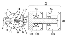
図7に本機構を用いてレールを把持するエレベータの安全装置の駆動装置の例を示す。駆動装置22は、ブレーキ解放時にバネ15の力に抗する力の大部分を永久磁石で保持し、残りの力と誤動作防止のために必要な力を電磁コイルによる力で保持するものである。駆動装置22は、永久磁石50と可動子51a、固定子52aからなる永久磁石用の磁路と、可動子51b、固定子52bからなる電磁石用の磁路を分割した構成となっている。可動子51aと51bは一体となって構成されている。永久磁石用の磁路にはバネ15に反発する力を発生し、主に可動子51aを解放状態に保持させる永久磁石50が配され、電磁石用の磁路には主に可動子51a、51bを解放状態に移動させ、移動後は永久磁石の保持力をアシストする電磁コイル53が配されている。可動子51a、51bをバネ15に抗して移動させるには、電磁コイル53に大きな電流が必要となるが、その時間は瞬間的であり大きな問題とはならない。
FIG. 7 shows an example of a drive device for an elevator safety device that grips a rail using this mechanism. The
この実施の形態1におけるガイドレール把持機構は、ガイドレール2とライニング12のギャップを広くとっても確実にガイドレール2を把持できるようにするためのものであり、駆動装置22の移動ストロークが長く、通常走行時すなわちブレーキ解放時はバネ15を圧縮する力も大きくなるため保持電力が大きくなってしまう。駆動装置22を上記のような構造とすることで、解放時の保持力の大部分を永久磁石50で保持するため、保持の電力を小さくすることができる。
The guide rail gripping mechanism according to the first embodiment is for ensuring that the
実施の形態2.
図8はこの発明の実施の形態2におけるエレベータの安全装置の駆動装置を示す構成図である。図7に示す実施の形態1おいては、永久磁石用の磁路と、電磁石用の磁路を直列に配置しているが、この実施の形態2は、図8に示すように、固定子52aと52b、可動子51aと51bをステンレスなどの非磁性体層54により区切り、別々の磁路を構成するように並列に配置して、電磁コイル53は非磁性体層54を挟んだ可動子51a、51bを囲むように固定子52a、52bの内面側に配置してもよい。また、永久磁石50は固定子52aのロッド18側の内面に配置され、可動子51aと対向している。
FIG. 8 is a configuration diagram showing a drive device for an elevator safety device according to
実施の形態3.
図9はこの発明の実施の形態3におけるエレベータの安全装置の伸縮ロッドを示す構成図である。
この実施の形態3は、バネをロッドに内蔵し、ロッド自体を伸縮可能な構成とした伸縮ロッド46に関するものである。具体的には、図8に示すように、左右リンク17と軸20で連結され、他端にバネ止め41が装着されたリンク側ロッド40と、このリンク側ロッド40を軸方向に摺動自在に装着されたバネ座42と、可動軸23と軸21で連結された可動軸側ロッド43と、この可動軸側ロッド43とバネ座42が一体となって動くための連結部材44と、バネ座42とバネ止め41に圧縮された状態で挟まれたバネ45により構成される。この実施の形態3では、連結部材44はバネ45とバネ止め41を囲うカップ形であり、その閉じた底部は可動軸側ロッド43と一体に構成され、開口部端にはネジが切ってある。バネ座42は連結部材44と同じくカップ形に加工され、その開口部端には連結部材44のネジと螺合するようにネジが切ってある。この構成により、バネ座42を回転させることで、軸20および軸21の距離を変化させ、ライニング12とレール2とのギャップを調整することが可能となる。
FIG. 9 is a configuration diagram showing the telescopic rod of the elevator safety device according to
The third embodiment relates to a
実施の形態1においては、かご室6内の乗客による偏荷重のためガイドレール2とライニング12の隙間がガイドレール2の両側で均等でなくなり、左右のリンク17の連結軸20と可動軸23の動作方向がずれた場合にロッド18が傾いて追従するが、そのとき駆動装置22のストロークによる隙間が均等の場合に比べ若干長くなってしまう。しかしながら、この実施の形態3によれば、伸縮ロッド46全体が力を伝達しながら伸縮できるので、駆動装置22のストロークは変わることがなく、寸法誤差の少ないエレベータの安全装置を提供することができる。
In the first embodiment, the gap between the
1 ブレーキ枠、 2 ガイドレール、 3 かご枠、 4 安全装置、 5 ガイド、 6 かご室、 7 防振ゴム、 10 ブロック、 10a バネ座、 10b つば、 11 アーム、 12 ライニング、 13 台座、 14 固定軸、 15 バネ、 16 バネ止め、 17 リンク、 18 ロッド、 18a リンク側ロッド、 18b 可動軸側ロッド、 18c 連結部材、 19,20,21 軸、 22 駆動装置、 23 可動軸、 30 球面座、 31 調整ネジ、 32 ストッパボルト、 33 球面ナット、 34 板バネ、 40 リンク側ロッド、 41バネ止め、 42バネ座、 43可動軸側ロッド、 44連結部材、 45 バネ、 46 伸縮ロッド、 50 永久磁石、 51a,51b 可動子、 52a,52b 固定子、 53 電磁コイル。 DESCRIPTION OF SYMBOLS 1 Brake frame, 2 Guide rail, 3 Car frame, 4 Safety device, 5 Guide, 6 Car room, 7 Anti-vibration rubber, 10 Block, 10a Spring seat, 10b Collar, 11 Arm, 12 Lining, 13 Base, 14 Fixed shaft , 15 spring, 16 spring stopper, 17 link, 18 rod, 18a link side rod, 18b movable shaft side rod, 18c connecting member, 19, 20, 21 shaft, 22 drive unit, 23 movable shaft, 30 spherical seat, 31 adjustment Screw, 32 stopper bolt, 33 spherical nut, 34 leaf spring, 40 link side rod, 41 spring stopper, 42 spring seat, 43 movable shaft side rod, 44 connecting member, 45 spring, 46 telescopic rod, 50 permanent magnet, 51a, 51b Movable element, 52a, 52b Stator, 5 3 Electromagnetic coil.
Claims (1)
Priority Applications (1)
| Application Number | Priority Date | Filing Date | Title |
|---|---|---|---|
| JP2005017988A JP4520319B2 (en) | 2005-01-26 | 2005-01-26 | Rail gripping mechanism and elevator safety device using the same |
Applications Claiming Priority (1)
| Application Number | Priority Date | Filing Date | Title |
|---|---|---|---|
| JP2005017988A JP4520319B2 (en) | 2005-01-26 | 2005-01-26 | Rail gripping mechanism and elevator safety device using the same |
Publications (2)
| Publication Number | Publication Date |
|---|---|
| JP2006206217A JP2006206217A (en) | 2006-08-10 |
| JP4520319B2 true JP4520319B2 (en) | 2010-08-04 |
Family
ID=36963488
Family Applications (1)
| Application Number | Title | Priority Date | Filing Date |
|---|---|---|---|
| JP2005017988A Expired - Fee Related JP4520319B2 (en) | 2005-01-26 | 2005-01-26 | Rail gripping mechanism and elevator safety device using the same |
Country Status (1)
| Country | Link |
|---|---|
| JP (1) | JP4520319B2 (en) |
Cited By (1)
| Publication number | Priority date | Publication date | Assignee | Title |
|---|---|---|---|---|
| US11608247B2 (en) | 2018-03-28 | 2023-03-21 | Inventio Ag | Caliper brake for an elevator system used as a holding and safety brake |
Families Citing this family (8)
| Publication number | Priority date | Publication date | Assignee | Title |
|---|---|---|---|---|
| DE502007007014D1 (en) * | 2007-11-12 | 2011-06-01 | Thyssenkrupp Elevator Ag | Braking device for braking a car |
| JP2013086933A (en) * | 2011-10-19 | 2013-05-13 | Hitachi Ltd | Elevator device |
| WO2014102933A1 (en) * | 2012-12-26 | 2014-07-03 | 三菱電機株式会社 | Elevator device |
| CN103601054B (en) * | 2013-10-22 | 2015-07-08 | 杭州沪宁电梯配件有限公司 | Combined elevator rail clamping device |
| CN103523633B (en) * | 2013-10-22 | 2015-09-09 | 杭州沪宁电梯配件有限公司 | A kind of elevator rail clamping device |
| CN106629303B (en) * | 2016-12-27 | 2018-11-30 | 廖忠民 | Horizontal electromagnetic lever safety braking device of gear rack lifting equipment |
| CN106629287B (en) * | 2016-12-27 | 2018-11-27 | 廖忠民 | On-orbit maintenance supporting device for gear rack lifting equipment |
| CN112027854B (en) * | 2020-07-09 | 2021-09-14 | 贵州梯安客机电设备有限公司 | Locking device for preventing elevator from accidentally falling |
Citations (3)
| Publication number | Priority date | Publication date | Assignee | Title |
|---|---|---|---|---|
| JP2002234683A (en) * | 2001-02-09 | 2002-08-23 | Mitsubishi Electric Building Techno Service Co Ltd | Upper and lower sliding door unlocking tool for elevator |
| WO2003037773A1 (en) * | 2001-10-30 | 2003-05-08 | Mitsubishi Denki Kabushiki Kaisha | Elevator device |
| WO2004083091A1 (en) * | 2003-03-18 | 2004-09-30 | Mitsubishi Denki Kabushiki Kaisha | Elevator device, and emergency stop device for elevator |
Family Cites Families (3)
| Publication number | Priority date | Publication date | Assignee | Title |
|---|---|---|---|---|
| JPS4946460U (en) * | 1972-07-28 | 1974-04-23 | ||
| JPH05147855A (en) * | 1991-11-25 | 1993-06-15 | Mitsubishi Electric Corp | Elevator brake releaser |
| JPH07172734A (en) * | 1993-12-20 | 1995-07-11 | Toshiba Corp | Balancing weight of elevator |
-
2005
- 2005-01-26 JP JP2005017988A patent/JP4520319B2/en not_active Expired - Fee Related
Patent Citations (3)
| Publication number | Priority date | Publication date | Assignee | Title |
|---|---|---|---|---|
| JP2002234683A (en) * | 2001-02-09 | 2002-08-23 | Mitsubishi Electric Building Techno Service Co Ltd | Upper and lower sliding door unlocking tool for elevator |
| WO2003037773A1 (en) * | 2001-10-30 | 2003-05-08 | Mitsubishi Denki Kabushiki Kaisha | Elevator device |
| WO2004083091A1 (en) * | 2003-03-18 | 2004-09-30 | Mitsubishi Denki Kabushiki Kaisha | Elevator device, and emergency stop device for elevator |
Cited By (1)
| Publication number | Priority date | Publication date | Assignee | Title |
|---|---|---|---|---|
| US11608247B2 (en) | 2018-03-28 | 2023-03-21 | Inventio Ag | Caliper brake for an elevator system used as a holding and safety brake |
Also Published As
| Publication number | Publication date |
|---|---|
| JP2006206217A (en) | 2006-08-10 |
Similar Documents
| Publication | Publication Date | Title |
|---|---|---|
| US6131704A (en) | Elevator rail brake | |
| CA2900980C (en) | Rotary actuator driven vibration isolation | |
| JP4520319B2 (en) | Rail gripping mechanism and elevator safety device using the same | |
| JP6623197B2 (en) | Vibration isolation with rotary actuator | |
| CN103052584B (en) | Rope braking apparatus | |
| US10501287B2 (en) | Damper unit for an elevator | |
| JP5911042B2 (en) | Brake device and elevator hoisting machine using the same | |
| US11649139B2 (en) | Electronic safety actuator assembly for elevator system | |
| KR101787226B1 (en) | Brake device, elevator hoist using same, and method for adjusting damping reaction force of brake device | |
| EP1124663A1 (en) | Linear motion brake | |
| JP2010071337A (en) | Brake torque rod mechanism of disc brake | |
| CN208310743U (en) | A kind of gravity drive beam pumping unit | |
| JP2006336733A (en) | Vertical base isolation unit and base isolation device using the same | |
| JP5697520B2 (en) | Elevator equipment | |
| JP2005320072A (en) | Elevator equipment | |
| CN110388194A (en) | A kind of gravity drive beam pumping unit | |
| JP2014162575A (en) | Resonance reduction device and resonance reduction method | |
| CN113092110A (en) | Bidirectional loading mechanism with buffer | |
| JP6541793B2 (en) | Elevator equipment | |
| CN208474374U (en) | A kind of brake | |
| JP6200640B2 (en) | Driving screw system with ball screw support unit | |
| CN115636368A (en) | Electromagnetic device for elevator brake, elevator brake and elevator system | |
| WO2023213672A1 (en) | Bounce damper for an elevator system | |
| JPH09229132A (en) | Magnetic spring type vibration damping device | |
| JP4622463B2 (en) | Elevator equipment |
Legal Events
| Date | Code | Title | Description |
|---|---|---|---|
| A621 | Written request for application examination |
Free format text: JAPANESE INTERMEDIATE CODE: A621 Effective date: 20061222 |
|
| A977 | Report on retrieval |
Free format text: JAPANESE INTERMEDIATE CODE: A971007 Effective date: 20090917 |
|
| A131 | Notification of reasons for refusal |
Free format text: JAPANESE INTERMEDIATE CODE: A131 Effective date: 20090929 |
|
| A521 | Written amendment |
Free format text: JAPANESE INTERMEDIATE CODE: A523 Effective date: 20091116 |
|
| A131 | Notification of reasons for refusal |
Free format text: JAPANESE INTERMEDIATE CODE: A131 Effective date: 20100323 |
|
| A521 | Written amendment |
Free format text: JAPANESE INTERMEDIATE CODE: A523 Effective date: 20100423 |
|
| TRDD | Decision of grant or rejection written | ||
| A01 | Written decision to grant a patent or to grant a registration (utility model) |
Free format text: JAPANESE INTERMEDIATE CODE: A01 Effective date: 20100518 |
|
| A01 | Written decision to grant a patent or to grant a registration (utility model) |
Free format text: JAPANESE INTERMEDIATE CODE: A01 |
|
| A61 | First payment of annual fees (during grant procedure) |
Free format text: JAPANESE INTERMEDIATE CODE: A61 Effective date: 20100520 |
|
| FPAY | Renewal fee payment (event date is renewal date of database) |
Free format text: PAYMENT UNTIL: 20130528 Year of fee payment: 3 |
|
| R150 | Certificate of patent or registration of utility model |
Ref document number: 4520319 Country of ref document: JP Free format text: JAPANESE INTERMEDIATE CODE: R150 Free format text: JAPANESE INTERMEDIATE CODE: R150 |
|
| FPAY | Renewal fee payment (event date is renewal date of database) |
Free format text: PAYMENT UNTIL: 20140528 Year of fee payment: 4 |
|
| R250 | Receipt of annual fees |
Free format text: JAPANESE INTERMEDIATE CODE: R250 |
|
| R250 | Receipt of annual fees |
Free format text: JAPANESE INTERMEDIATE CODE: R250 |
|
| R250 | Receipt of annual fees |
Free format text: JAPANESE INTERMEDIATE CODE: R250 |
|
| R250 | Receipt of annual fees |
Free format text: JAPANESE INTERMEDIATE CODE: R250 |
|
| R250 | Receipt of annual fees |
Free format text: JAPANESE INTERMEDIATE CODE: R250 |
|
| LAPS | Cancellation because of no payment of annual fees |