JP4454078B2 - Endoscope bending tube and method of manufacturing the same - Google Patents
Endoscope bending tube and method of manufacturing the same Download PDFInfo
- Publication number
- JP4454078B2 JP4454078B2 JP28800499A JP28800499A JP4454078B2 JP 4454078 B2 JP4454078 B2 JP 4454078B2 JP 28800499 A JP28800499 A JP 28800499A JP 28800499 A JP28800499 A JP 28800499A JP 4454078 B2 JP4454078 B2 JP 4454078B2
- Authority
- JP
- Japan
- Prior art keywords
- bending tube
- hole
- connecting portion
- fitting
- endoscope
- Prior art date
- Legal status (The legal status is an assumption and is not a legal conclusion. Google has not performed a legal analysis and makes no representation as to the accuracy of the status listed.)
- Expired - Fee Related
Links
- 238000005452 bending Methods 0.000 title claims description 43
- 238000004519 manufacturing process Methods 0.000 title claims description 12
- 238000000034 method Methods 0.000 claims description 5
- 238000003780 insertion Methods 0.000 description 8
- 230000037431 insertion Effects 0.000 description 8
- 238000003825 pressing Methods 0.000 description 3
- 230000000694 effects Effects 0.000 description 2
- 230000004048 modification Effects 0.000 description 2
- 238000012986 modification Methods 0.000 description 2
- 230000002093 peripheral effect Effects 0.000 description 2
- 230000015572 biosynthetic process Effects 0.000 description 1
Images


Classifications
-
- A—HUMAN NECESSITIES
- A61—MEDICAL OR VETERINARY SCIENCE; HYGIENE
- A61B—DIAGNOSIS; SURGERY; IDENTIFICATION
- A61B1/00—Instruments for performing medical examinations of the interior of cavities or tubes of the body by visual or photographical inspection, e.g. endoscopes; Illuminating arrangements therefor
- A61B1/005—Flexible endoscopes
- A61B1/0051—Flexible endoscopes with controlled bending of insertion part
- A61B1/0055—Constructional details of insertion parts, e.g. vertebral elements
-
- A—HUMAN NECESSITIES
- A61—MEDICAL OR VETERINARY SCIENCE; HYGIENE
- A61B—DIAGNOSIS; SURGERY; IDENTIFICATION
- A61B17/00—Surgical instruments, devices or methods
- A61B17/00234—Surgical instruments, devices or methods for minimally invasive surgery
- A61B2017/00292—Surgical instruments, devices or methods for minimally invasive surgery mounted on or guided by flexible, e.g. catheter-like, means
- A61B2017/003—Steerable
- A61B2017/00305—Constructional details of the flexible means
- A61B2017/00314—Separate linked members
-
- A—HUMAN NECESSITIES
- A61—MEDICAL OR VETERINARY SCIENCE; HYGIENE
- A61B—DIAGNOSIS; SURGERY; IDENTIFICATION
- A61B17/00—Surgical instruments, devices or methods
- A61B17/00234—Surgical instruments, devices or methods for minimally invasive surgery
- A61B2017/00292—Surgical instruments, devices or methods for minimally invasive surgery mounted on or guided by flexible, e.g. catheter-like, means
- A61B2017/003—Steerable
- A61B2017/00318—Steering mechanisms
- A61B2017/00323—Cables or rods
- A61B2017/00327—Cables or rods with actuating members moving in opposite directions
-
- Y—GENERAL TAGGING OF NEW TECHNOLOGICAL DEVELOPMENTS; GENERAL TAGGING OF CROSS-SECTIONAL TECHNOLOGIES SPANNING OVER SEVERAL SECTIONS OF THE IPC; TECHNICAL SUBJECTS COVERED BY FORMER USPC CROSS-REFERENCE ART COLLECTIONS [XRACs] AND DIGESTS
- Y10—TECHNICAL SUBJECTS COVERED BY FORMER USPC
- Y10T—TECHNICAL SUBJECTS COVERED BY FORMER US CLASSIFICATION
- Y10T29/00—Metal working
- Y10T29/49—Method of mechanical manufacture
- Y10T29/49826—Assembling or joining
- Y10T29/49833—Punching, piercing or reaming part by surface of second part
-
- Y—GENERAL TAGGING OF NEW TECHNOLOGICAL DEVELOPMENTS; GENERAL TAGGING OF CROSS-SECTIONAL TECHNOLOGIES SPANNING OVER SEVERAL SECTIONS OF THE IPC; TECHNICAL SUBJECTS COVERED BY FORMER USPC CROSS-REFERENCE ART COLLECTIONS [XRACs] AND DIGESTS
- Y10—TECHNICAL SUBJECTS COVERED BY FORMER USPC
- Y10T—TECHNICAL SUBJECTS COVERED BY FORMER US CLASSIFICATION
- Y10T29/00—Metal working
- Y10T29/49—Method of mechanical manufacture
- Y10T29/49826—Assembling or joining
- Y10T29/49908—Joining by deforming
- Y10T29/49938—Radially expanding part in cavity, aperture, or hollow body
Landscapes
- Health & Medical Sciences (AREA)
- Life Sciences & Earth Sciences (AREA)
- Surgery (AREA)
- Biomedical Technology (AREA)
- Medical Informatics (AREA)
- Optics & Photonics (AREA)
- Pathology (AREA)
- Radiology & Medical Imaging (AREA)
- Biophysics (AREA)
- Engineering & Computer Science (AREA)
- Physics & Mathematics (AREA)
- Heart & Thoracic Surgery (AREA)
- Nuclear Medicine, Radiotherapy & Molecular Imaging (AREA)
- Molecular Biology (AREA)
- Animal Behavior & Ethology (AREA)
- General Health & Medical Sciences (AREA)
- Public Health (AREA)
- Veterinary Medicine (AREA)
- Endoscopes (AREA)
- Instruments For Viewing The Inside Of Hollow Bodies (AREA)
Description
【0001】
【発明の属する技術分野】
この発明は、内視鏡の湾曲管およびその製造方法に関する。
【0002】
【従来の技術】
一般に、内視鏡は、本体から細長い挿入部が延び、この挿入部の先端に本体側で遠隔操作される湾曲管が設けられている。この湾曲管は、一列に並べられた多数の管形状をなす関節駒を備えている。各関節駒の一端部には、一対の第1連結部が周方向に180度離れて配され、他端部にも一対の第2連結部が同様に配されている。そして、隣接する関節駒の第1、第2連結部どうしが、径方向に重ねられ、リベット(軸部材)によって回転可能に連結されている。これによって、湾曲管が全体として湾曲可能になっている。
【0003】
近年、湾曲管の極細化、すなわち関節駒の径の微小化が要望されている。例えば、直径で1〜2mm程度、もしくはそれ以下にすることが求められている。しかし、上記の一般構造では、関節駒が小径になればなるほど、リベットによる連結作業が困難になる。そこで、特許第2619949号公報に記載の湾曲管では、第1連結部に貫通孔が形成されるとともに、第2連結部に関節駒の軸方向に突出する凸片が設けられている。この凸片が上記貫通孔に通された後、180度折り曲げられている。これによって、隣接する関節駒どうしが、リベット無しで連結されている。
【0004】
【発明が解決しようとする課題】
上掲公報に記載の湾曲管では、リベットが無いので極細化が可能であるが、凸片と貫通孔との摩擦抵抗が大きいため、湾曲操作がしづらいという問題があった。本発明は、上記事情に鑑みてなされたものであり、その目的とするところは、隣接する関節駒をリベット無しで連結して極細化を可能にするとともに、円滑な湾曲操作が可能な内視鏡の湾曲管を提供することにある。
【0005】
【課題を解決するための手段】
上記問題を解決するために、第1の発明は、一列に並べられた複数の管形状をなす関節駒を備え、各関節駒には、一端部の周方向に180度離れて一対の第1連結部が配され、他端部の周方向に180度離れて一対の第2連結部が配され、隣接する関節駒の第1、第2連結部どうしが、径方向に重ねられ回転可能に連結された内視鏡の湾曲管において、上記第1連結部に、凹みまたは貫通孔からなる嵌合部が形成され、上記第2連結部に、凸部が形成され、上記嵌合部の円または円弧をなす内周と、上記凸部の円または円弧をなす外周が擦れ合うようにして、上記凸部が上記嵌合部に回転可能に嵌め込まれ、この凸部と嵌合部との嵌め合いのみによって隣接する関節駒の第1、第2連結部どうしが連結されていることを特徴とする。
【0006】
第2の発明は、第1の発明において、上記嵌合部の内周が円をなし、上記凸部が円筒形状をなしていることを特徴とする。
【0007】
第3の発明は、第1または第2の発明において、上記径方向に沿って上記第1連結部が内側に、上記第2連結部が外側に位置され、上記凸部が、上記第2連結部から径方向内側に突出され上記第1連結部の嵌合部に嵌め込まれていることを特徴とする。
【0008】
第4の発明は、第1〜第3の発明の何れかにおいて、上記嵌合部が貫通孔からなり、上記凸部がこの貫通孔を貫通するとともに、この凸部の先端に、上記貫通孔の縁に係止される環状の係止部が設けられていることを特徴とする。
【0009】
第5の発明は、管形状をなし、一端部の周方向に180度離れて一対の第1連結部が配され、他端部の周方向に180度離れて一対の第2連結部が配された複数の関節駒を一列状に並べ、隣接する関節駒の第1、第2連結部どうしを径方向に重ねて回転可能に連結してなる内視鏡の湾曲管の製造方法において、上記第1連結部に貫通孔を形成しておき、この第1連結部の径方向外側に上記第2連結部を重ね、この第2連結部の上記貫通孔に対応する箇所を外側からプレスすることにより、径方向内側に突出するとともに上記貫通孔に回転可能に嵌り込んだ凸部を成形し、この凸部と貫通孔との嵌め合いのみによって隣接する関節駒どうしを連結することを特徴とする。
【0010】
第6の発明は、管形状をなし、一端部の周方向に180度離れて一対の第1連結部が配され、他端部の周方向に180度離れて一対の第2連結部が配された複数の関節駒を一列状に並べ、隣接する関節駒の第1、第2連結部どうしを径方向に重ねて回転可能に連結してなる内視鏡の湾曲管の製造方法において、上記第1連結部の径方向外側に上記第2連結部を重ね、この重ねられた第1、第2連結部を外側からプレスすることによって、第1連結部には、径方向内側に凹む凹部を、第2連結部には、径方向内側に突出する凸部を、それぞれ同時成形しながら、上記凸部が上記凹部に回転可能に嵌り込んだ状態にし、この凸部と凹部との嵌め合いのみによって隣接する関節駒どうしを連結することを特徴とする。
【0011】
【発明の実施の形態】
以下、本発明の実施形態を、図面を参照して説明する。
はじめに、湾曲管が用いられる内視鏡Aについて、図5に基づいて概説しておく。内視鏡Aは、本体1と、この本体1から延びて体内に挿入される挿入部2とを備えている。本体1には、接眼部3やつまみ4が設けられている。挿入部2は、フレキシブルに形成されており、その先端に上記つまみ4によって遠隔操作される湾曲部5が設けられている。湾曲部5の先端には、先端構成部6が設けられている。先端構成部6には、観察窓(図示せず)が設けられており、体内の像がこの観察窓に入射され、接眼部3に伝送される。
【0012】
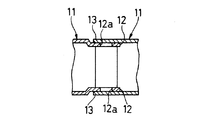
この発明に係る湾曲管10は、湾曲部5の内部に設けられている。図1に示すように、湾曲管10は、管形状をなす多数の関節駒11を備えている。これら関節駒11は、一列状に並べられ、隣接するものの端部どうしが、回転可能に連結されている。この連結構造は、本発明の要旨であるので、追って詳述する。
【0013】
各関節駒11の軸方向の中央には、周方向に180度離れて一対のワイヤ挿通孔11aが設けられている。これらワイヤ挿通孔11aに、一対の操作ワイヤ20がそれぞれ挿通されている。図示は省略するが、操作ワイヤ20の一端は、一番先端に配された関節駒11または先端構成部6に止着され、他端は、上記つまみ4に連繋されている。図5において仮想線で示すように、つまみ4を一方向に回転操作すると、一方の操作ワイヤ20が引っ張られ、反対方向に回転操作すると、他方の操作ワイヤ20が引っ張られる。これによって、湾曲管10ひいては湾曲部5が2方向に湾曲される。
【0014】
隣接する関節駒11の端部どうしの連結構造について説明する。
図1〜図3に示すように、各関節駒11の一端部には、周方向に180度離れて一対の第1連結片12(第1連結部)が設けられている。これら第1連結片12は、ワイヤ挿通孔11aから周方向に90度ずれて配されている。各第1連結片12は、平らな円板形状をなし、約半分が関節駒11の軸方向に突出されている。第1連結片12の中央には、円形の貫通孔12a(嵌合部)が形成されている。。
【0015】
同様にして、各関節駒11の他端部には、周方向に180度離れて一対の第2連結片13(第2連結部)が突出して設けられている。第2連結片13は、関節駒11の軸方向に沿って第1連結片12と一直線をなす位置に配されている。第2連結片13は、平らな円板形状をなし、その中央には、径方向内側に突出する円筒形状をなす凸部13aが設けられている。凸部13aにおいて径方向内側を向く先端部は、閉塞されている。
【0016】
隣接する2つの関節駒11において、一方の関節駒11の第1連結片12と他方の関節駒11の第2連結片13とが、周方向に一致させられ、第1連結片12の径方向外側に第2連結片13が重ねられている。そして、第1連結片12の貫通孔12aに第2連結片13の凸部13aが嵌め込まれている。しかも、貫通孔12aの円形をなす内周と凸部13aの円形をなす外周とが擦れ合うことにより、回転可能な嵌め込み状態になっている。これによって、隣接する関節駒11が、一対の第1、第2連結片12,13どうしを結ぶ軸線のまわりに回転可能に連結されている。
【0017】
上記構成による作用について説明する。
第1、第2連結片12,13どうしの連結は、貫通孔12aと凸部13aとの嵌め合いのみによってなされ、リベット(軸部材)を必要としない。したがって、関節駒11が極めて小径であっても、楽に連結することができ、湾曲管10の極細化を図ることができる。しかも、凸部13aの円形をなす外周が貫通孔12aの円形をなす内周と擦れ合うことにより、隣接する関節駒11どうしを円滑に相対回転させることができ、ひいては湾曲管10を円滑に湾曲操作することができる。
【0018】
図4に示すように、第1、第2連結片12,13どうしを連結する際は、第1連結片12に貫通孔12aを予め開けておく。そのうえで隣接する関節駒11の第1、第2連結片12,13どうしを径方向に重ねる。そして、図3に示すように、第2連結片13を外側からプレスすることによって、凸部13aを成形すると同時に、この凸部13aを貫通孔12aに嵌め込む。凸部13aが出来るのと同時に第1、第2連結片12,13を連結できるので、工数を減らすことができ、湾曲管10の製造時間を短縮できる。
【0019】
上記の連結作業は、一番基端側の関節駒11から順次先端側に向けて行ってもよく、一番先端側の関節駒11から順次基端側に向けて行ってもよい。全ての関節駒11を連結し終えた後、ワイヤ挿通孔11aに操作ワイヤ20を通す。なお、新たに連結する関節駒11に予め操作ワイヤ20を通した後、第1、第2連結片12,13の連結を行ってもよい。
【0020】
次に、本発明の他の実施形態について説明する。これら他の実施形態において、上記第1実施形態と同様の構成に関しては、同一符号を付して説明を簡略化する。図6は、本発明の第2実施形態を示したものである。この実施形態では、凸部13a’において径方向内側を向く先端部が開口されている。
【0021】
図7は、本発明の第3実施形態を示したものである。この実施形態は、上記第2実施形態の変形例であって、凸部13a’の先端部に、貫通孔12aの縁に係止する環状の係止部13bが形成されている。これによって、隣接する関節駒11の第1、第2連結片12,13どうしが外れるのを確実に防止することができる。
【0022】
図8は、本発明の第4実施形態を示したものである。この実施形態では、第1連結片12に、貫通孔12aに代えて、凹部12a’(嵌合部)が形成されている。凹部12a’は、径方向内側に向けて凹み、その内周面は円筒面をなしている(内周が円形をなしている)。この凹部12a’に凸部13aが嵌め込まれている。
【0023】
この第4実施形態における隣接する関節駒11の第1、第2連結片12,13どうしの連結方法を説明する。図9に示すように、第1、第2連結片12,13は、凹部12a’、凸部13aがそれぞれ未形成の状態で重ねられる。その後、図8に示すように、重ねられた第1、第2連結片12,13を外側からプレスすることによって、凹部12a’および凸部13aを同時成形しながら、互いに嵌め合わされた状態にする。この第4実施形態では、第1連結片12に予め嵌合部を形成しておく工程が省略されるので、湾曲管10の製造時間を一層短縮することができる。
【0024】
図10〜図13に示す第5〜第8実施形態は、第1、第2連結片12,13の重ね方が上記第1〜第4実施形態と逆になっている。すなわち、湾曲管10の径方向に沿って外側に第1連結片12が、内側に第2連結片13が位置するように重ねられている。個々に説明すると、図10に示す第5実施形態では、先端閉塞の凸部13aが、第2連結片13から径方向外側に向けて突出され、第1連結片12の貫通孔12aに嵌め込まれている。
【0025】
図11に示す第6実施形態では、先端開口の凸部13a’が、径方向外側に突出され、貫通孔12aに嵌め込まれている。図12に示す第7実施形態では、径方向外側に突出した凸部13a’の先端に環状の係止部13bが設けられ、この係止部13bが貫通孔12aの縁に係止されている。図13に示す第8実施形態では、第1連結片12に径方向外側へ凹む凹部12a’が形成され、この凹部12a’に第2連結片13の径方向外側へ突出する凸部13aが嵌め込まれている。
【0026】
図14は、本発明の第9実施形態を示したものである。この実施形態では、第2連結片13に形成された凸部13a”の外周が、平らな半円形をなす一対の平取り部13cと、これら平取り部13cの周縁部間に設けられた丸み部13dとを有している。丸み部13dは、一方の平取り部13cから他方の平取り部13cに向かう方向に沿って円弧を描いている。この丸み部13dが、貫通孔12aの内周と擦れ合い、関節駒11どうしが円滑に相対回転される。
【0027】
図15は、本発明の第10実施形態を示したものである。この実施形態は、上記第9実施形態の変形例であって、第1連結片12の貫通孔12a”の内周が、凸部13a”の丸み部13dと擦れ合う一対の円弧部12bと、これら円弧部12b間に設けられ、平取り部13cから離間された一対の直線部12cとを有している。
【0028】
本発明は、上記実施形態に限定されるものでなく、種々の形態を採用可能である。
例えば、4方向に湾曲可能な湾曲管にも適用できる。カテーテルにも応用できる。
第1連結片12には貫通孔12a,12a”または凹部12a’を、第2連結片13には凸部13a,13a’,13a”を、それぞれ予め形成しておき、これら第1、第2連結片12,13を弾性変形させることによって、貫通孔12a,12a”または凹部12a’に凸部13a,13a’,13a”を嵌め込んでもよい。
【0029】
【発明の効果】
以上説明したように、第1の発明は、隣接する関節駒の第1、第2連結部どうしをリベット無しで連結でき、湾曲管の極細化が可能になるとともに、凸部と嵌合部にそれぞれ丸みを持たせることによって、円滑な湾曲操作を行うことができる。
第2の発明は、湾曲操作を確実に円滑に行うことができる。
第3の発明では、第2連結部を外側からプレスすることによって、凸部を容易に形成することができる。
第4の発明では、凸部が貫通孔から外れるのを確実に防止することができる。第5の発明では、凸部を形成すると同時に、第1、第2連結部どうしを連結することができ、湾曲管の製造時間を短縮することができる。
第6の発明では、凹部と凸部を形成すると同時に、第1、第2連結部どうしを連結することができ、湾曲管の製造時間を一層短縮することができる。
【図面の簡単な説明】
【図1】本発明の第1実施形態に係る内視鏡の湾曲管を、一部断面で示す側面図である。
【図2】上記湾曲管の隣接する2つの関節駒の分解斜視図である。
【図3】図1のIII−III線に沿う断面図である。
【図4】上記隣接する関節駒の連結工程を、第1、第2連結片を重ねた状態で示す断面図である。
【図5】内視鏡の側面図である。
【図6】本発明の第2実施形態を示す断面図である。
【図7】本発明の第3実施形態を示す断面図である。
【図8】本発明の第4実施形態を示す断面図である。
【図9】上記第4実施形態に係る隣接する関節駒の連結工程を、第1、第2連結片を重ねた状態で示す断面図である。
【図10】本発明の第5実施形態を示す断面図である。
【図11】本発明の第6実施形態を示す断面図である。
【図12】本発明の第7実施形態を示す断面図である。
【図13】本発明の第8実施形態を示す断面図である。
【図14】本発明の第9実施形態を示す分解斜視図である。
【図15】本発明の第10実施形態を示す断面図である。
【符号の説明】
A 内視鏡
10 湾曲管
11 関節駒
12 第1連結片(第1連結部)
12a,12a” 貫通孔(嵌合部)
12a’ 凹部(嵌合部)
13 第2連結片(第2連結部)
13a,13a’,13a” 凸部
13b 係止部[0001]
BACKGROUND OF THE INVENTION
The present invention relates to an endoscope bending tube and a method of manufacturing the same.
[0002]
[Prior art]
In general, an endoscope has an elongated insertion portion extending from a main body, and a bending tube that is remotely operated on the main body side is provided at the distal end of the insertion portion. This curved tube is provided with a number of joint pieces having a plurality of tube shapes arranged in a row. A pair of first connecting portions are arranged 180 degrees apart in the circumferential direction at one end of each joint piece, and a pair of second connecting portions are similarly arranged at the other end. And the 1st, 2nd connection part of the adjacent joint piece is piled up in radial direction, and is connected rotatably by the rivet (shaft member). Thereby, the bending tube can be bent as a whole.
[0003]
In recent years, there has been a demand for ultra-fine bending of the bending tube, that is, miniaturization of the diameter of the joint piece. For example, the diameter is required to be about 1 to 2 mm or less. However, in the above-described general structure, the smaller the joint piece is, the more difficult it is to connect with rivets. Therefore, in the bending tube described in Japanese Patent No. 26199949, a through hole is formed in the first connecting portion, and a convex piece protruding in the axial direction of the joint piece is provided in the second connecting portion. After this convex piece is passed through the through hole, it is bent 180 degrees. As a result, the adjacent joint pieces are connected without rivets.
[0004]
[Problems to be solved by the invention]
The bending tube described in the above publication can be made very thin because there is no rivet, but there is a problem that the bending operation is difficult because the frictional resistance between the convex piece and the through hole is large. The present invention has been made in view of the above circumstances, and an object of the present invention is to provide an internal view in which adjacent joint pieces are connected without a rivet to enable ultra-thinning and a smooth bending operation is possible. It is to provide a curved tube of a mirror.
[0005]
[Means for Solving the Problems]
In order to solve the above-mentioned problem, the first invention includes a plurality of joint pieces having a tube shape arranged in a line, and each joint piece is separated from the pair of first pieces by 180 degrees in the circumferential direction of one end. A connecting portion is arranged, a pair of second connecting portions are arranged 180 degrees apart in the circumferential direction of the other end portion, and the first and second connecting portions of adjacent joint pieces are overlapped in the radial direction and connected to be rotatable. In the bent tube of the endoscope, a fitting portion made of a recess or a through hole is formed in the first connecting portion, a convex portion is formed in the second connecting portion, and a circle of the fitting portion or The convex part is rotatably fitted into the fitting part so that the inner circumference forming the arc and the circle of the convex part or the outer circumference forming the arc rub against each other, and only the fitting of the convex part and the fitting part is fitted. The first and second connecting portions of the adjacent joint pieces are connected to each other.
[0006]
A second invention is characterized in that, in the first invention, the inner periphery of the fitting portion forms a circle, and the convex portion has a cylindrical shape.
[0007]
According to a third invention, in the first or second invention, the first connecting portion is located inside, the second connecting portion is located outside, and the convex portion is located along the radial direction. It protrudes inward in the radial direction from the portion, and is fitted into the fitting portion of the first connecting portion.
[0008]
According to a fourth invention, in any one of the first to third inventions, the fitting portion includes a through hole, the convex portion penetrates the through hole, and the through hole is formed at a tip of the convex portion. An annular locking portion that is locked to the edge of the ring is provided.
[0009]
According to a fifth aspect of the present invention, a pipe shape is formed, a pair of first connection portions are arranged 180 degrees apart in the circumferential direction of one end portion, and a pair of second connection portions are arranged 180 degrees apart in the circumferential direction of the other end portion. In the method of manufacturing a bending tube for an endoscope, wherein the plurality of joint pieces arranged in a line and the first and second connecting portions of adjacent joint pieces are connected to each other so as to be rotatable in a radial direction. By forming a through hole in one connecting part, overlaying the second connecting part on the radially outer side of the first connecting part, and pressing the part corresponding to the through hole of the second connecting part from the outside A convex portion protruding radially inward and rotatably fitted in the through hole is formed, and adjacent joint pieces are connected only by fitting the convex portion and the through hole.
[0010]
According to a sixth aspect of the present invention, a pipe shape is formed, a pair of first connection portions are arranged 180 degrees apart in the circumferential direction of one end portion, and a pair of second connection portions are arranged 180 degrees apart in the circumferential direction of the other end portion. In the method of manufacturing a bending tube for an endoscope, the plurality of joint pieces are arranged in a line, and the first and second connecting portions of adjacent joint pieces are overlapped in a radial direction and rotatably connected. The second connecting portion is overlapped on the radially outer side of the one connecting portion, and the first connecting portion and the second connecting portion that are overlapped are pressed from the outer side, whereby the first connecting portion has a concave portion recessed radially inward. In the second connecting portion, a convex portion protruding radially inward is simultaneously formed, and the convex portion is rotatably fitted in the concave portion, and only by fitting the convex portion and the concave portion. It is characterized by connecting adjacent joint pieces.
[0011]
DETAILED DESCRIPTION OF THE INVENTION
Embodiments of the present invention will be described below with reference to the drawings.
First, an endoscope A using a bending tube will be outlined based on FIG. The endoscope A includes a main body 1 and an
[0012]
The
[0013]
A pair of
[0014]
A connection structure between end portions of adjacent
As shown in FIGS. 1 to 3, one end portion of each
[0015]
Similarly, at the other end of each
[0016]
In two adjacent
[0017]
The effect | action by the said structure is demonstrated.
The first and second connecting
[0018]
As shown in FIG. 4, when connecting the first and second connecting
[0019]
The connecting operation may be performed sequentially from the most proximal
[0020]
Next, another embodiment of the present invention will be described. In these other embodiments, the same components as those in the first embodiment are denoted by the same reference numerals, and the description will be simplified. FIG. 6 shows a second embodiment of the present invention. In this embodiment, the tip portion that faces radially inward in the
[0021]
FIG. 7 shows a third embodiment of the present invention. This embodiment is a modification of the second embodiment, and an
[0022]
FIG. 8 shows a fourth embodiment of the present invention. In this embodiment, a
[0023]
A connection method between the first and
[0024]
In the fifth to eighth embodiments shown in FIGS. 10 to 13, the first and second connecting
[0025]
In 6th Embodiment shown in FIG. 11,
[0026]
FIG. 14 shows a ninth embodiment of the present invention. In this embodiment, the outer periphery of the
[0027]
FIG. 15 shows a tenth embodiment of the present invention. This embodiment is a modification of the ninth embodiment, and a pair of
[0028]
The present invention is not limited to the above embodiment, and various forms can be adopted.
For example, the present invention can be applied to a bending tube that can be bent in four directions. It can also be applied to catheters.
Through
[0029]
【The invention's effect】
As described above, according to the first invention, the first and second connecting portions of the adjacent joint pieces can be connected without rivets, the bending tube can be made extremely thin, and the convex portion and the fitting portion can be respectively connected. By providing the roundness, a smooth bending operation can be performed.
According to the second aspect of the invention, the bending operation can be performed smoothly and reliably.
In 3rd invention, a convex part can be easily formed by pressing a 2nd connection part from the outer side.
In 4th invention, it can prevent reliably that a convex part remove | deviates from a through-hole. In the fifth invention, the first and second connecting portions can be connected to each other at the same time as the convex portions are formed, and the manufacturing time of the bending tube can be shortened.
In the sixth aspect of the invention, the first and second connecting portions can be connected to each other at the same time when the concave portion and the convex portion are formed, and the manufacturing time of the bending tube can be further shortened.
[Brief description of the drawings]
FIG. 1 is a side view showing a partial cross section of a bending tube of an endoscope according to a first embodiment of the present invention.
FIG. 2 is an exploded perspective view of two adjacent joint pieces of the bending tube.
3 is a cross-sectional view taken along line III-III in FIG.
FIG. 4 is a cross-sectional view showing the connecting step of the adjacent joint pieces in a state where the first and second connecting pieces are overlapped.
FIG. 5 is a side view of the endoscope.
FIG. 6 is a cross-sectional view showing a second embodiment of the present invention.
FIG. 7 is a cross-sectional view showing a third embodiment of the present invention.
FIG. 8 is a cross-sectional view showing a fourth embodiment of the present invention.
FIG. 9 is a cross-sectional view showing a connecting process of adjacent joint pieces according to the fourth embodiment in a state where first and second connecting pieces are stacked.
FIG. 10 is a sectional view showing a fifth embodiment of the present invention.
FIG. 11 is a cross-sectional view showing a sixth embodiment of the present invention.
FIG. 12 is a cross-sectional view showing a seventh embodiment of the present invention.
FIG. 13 is a sectional view showing an eighth embodiment of the present invention.
FIG. 14 is an exploded perspective view showing a ninth embodiment of the present invention.
FIG. 15 is a sectional view showing a tenth embodiment of the present invention.
[Explanation of symbols]
A
12a, 12a "Through hole (fitting part)
12a 'recess (fitting part)
13 2nd connection piece (2nd connection part)
13a, 13a ', 13a "
Claims (5)
上記第1連結部に、凹みまたは貫通孔からなる嵌合部が形成され、上記第2連結部に、凸部が形成され、上記嵌合部の円または円弧をなす内周と、上記凸部の円または円弧をなす外周が擦れ合うようにして、上記凸部が上記嵌合部に回転可能に嵌め込まれ、この凸部と嵌合部との嵌め合いのみによって隣接する関節駒の第1、第2連結部どうしが連結されており、上記嵌合部の内周が円形をなし、上記凸部が円筒形状をなしていることを特徴とする内視鏡の湾曲管。A plurality of joint pieces having a tube shape arranged in a row are provided, and each joint piece is provided with a pair of first connecting portions 180 degrees apart in the circumferential direction of one end and 180 in the circumferential direction of the other end. In a bending tube of an endoscope in which a pair of second connection portions are arranged apart from each other, and the first and second connection portions of adjacent joint pieces are connected to each other in a radially overlapped manner.
A fitting part made of a recess or a through hole is formed in the first connecting part, a convex part is formed in the second connecting part, an inner circumference forming a circle or an arc of the fitting part, and the convex part The projections are rotatably fitted in the fitting portions so that the outer circumferences of the circles or arcs of the two are rubbed together, and the first and second joint pieces adjacent to each other only by fitting the projections and the fitting portions. A bending tube for an endoscope, characterized in that the connecting portions are connected, the inner periphery of the fitting portion is circular, and the convex portion is cylindrical .
上記第1連結部に貫通孔を形成しておき、この第1連結部の径方向外側に上記第2連結部を重ね、この第2連結部の上記貫通孔に対応する箇所を外側からプレスすることにより、径方向内側に突出するとともに上記貫通孔に回転可能に嵌り込んだ凸部を成形し、この凸部と貫通孔との嵌め合いのみによって隣接する関節駒どうしを連結することを特徴とする内視鏡の湾曲管の製造方法。A plurality of joint pieces having a tubular shape and having a pair of first connecting portions arranged 180 degrees apart in the circumferential direction of one end and a pair of second connecting portions arranged 180 degrees apart in the circumferential direction of the other end In the manufacturing method of the bending tube of the endoscope, in which the first and second connecting portions of the adjacent joint pieces are connected to each other so as to be rotatable in a radial direction.
A through hole is formed in the first connecting portion, the second connecting portion is overlapped on the radially outer side of the first connecting portion, and a portion corresponding to the through hole of the second connecting portion is pressed from the outside. By forming a convex portion that protrudes radially inward and rotatably fitted in the through hole, the adjacent joint pieces are connected only by fitting the convex portion and the through hole. A method of manufacturing a bending tube of an endoscope.
上記第1連結部の径方向外側に上記第2連結部を重ね、この重ねられた第1、第2連結部を外側からプレスすることによって、第1連結部には、径方向内側に凹む凹部を、第2連結部には、径方向内側に突出する凸部を、それぞれ同時成形しながら、上記凸部が上記凹部に回転可能に嵌り込んだ状態にし、この凸部と凹部との嵌め合いのみによって隣接する関節駒どうしを連結することを特徴とする内視鏡の湾曲管の製造方法。A plurality of joint pieces having a tubular shape and having a pair of first connecting portions arranged 180 degrees apart in the circumferential direction of one end and a pair of second connecting portions arranged 180 degrees apart in the circumferential direction of the other end In the manufacturing method of the bending tube of the endoscope, in which the first and second connecting portions of the adjacent joint pieces are connected to each other so as to be rotatable in a radial direction.
The second connecting portion is overlapped on the radially outer side of the first connecting portion, and the first connecting portion and the second connecting portion that are overlapped are pressed from the outside so that the first connecting portion has a recess recessed radially inward. In the second connecting portion, a convex portion protruding radially inward is simultaneously formed, and the convex portion is rotatably fitted in the concave portion, and the convex portion and the concave portion are fitted to each other. A method for manufacturing a bending tube of an endoscope, characterized in that adjacent joint pieces are connected to each other only by the above-described method.
Priority Applications (4)
| Application Number | Priority Date | Filing Date | Title |
|---|---|---|---|
| JP28800499A JP4454078B2 (en) | 1999-10-08 | 1999-10-08 | Endoscope bending tube and method of manufacturing the same |
| DE60007051T DE60007051T2 (en) | 1999-10-08 | 2000-09-13 | Flexible tube and its manufacture |
| EP00307923A EP1090581B1 (en) | 1999-10-08 | 2000-09-13 | Bendable tube and method for manufacturing the same |
| US09/669,110 US6408889B1 (en) | 1999-10-08 | 2000-09-25 | Bendable tube and method for manufacturing the same |
Applications Claiming Priority (1)
| Application Number | Priority Date | Filing Date | Title |
|---|---|---|---|
| JP28800499A JP4454078B2 (en) | 1999-10-08 | 1999-10-08 | Endoscope bending tube and method of manufacturing the same |
Publications (2)
| Publication Number | Publication Date |
|---|---|
| JP2001104239A JP2001104239A (en) | 2001-04-17 |
| JP4454078B2 true JP4454078B2 (en) | 2010-04-21 |
Family
ID=17724572
Family Applications (1)
| Application Number | Title | Priority Date | Filing Date |
|---|---|---|---|
| JP28800499A Expired - Fee Related JP4454078B2 (en) | 1999-10-08 | 1999-10-08 | Endoscope bending tube and method of manufacturing the same |
Country Status (4)
| Country | Link |
|---|---|
| US (1) | US6408889B1 (en) |
| EP (1) | EP1090581B1 (en) |
| JP (1) | JP4454078B2 (en) |
| DE (1) | DE60007051T2 (en) |
Families Citing this family (79)
| Publication number | Priority date | Publication date | Assignee | Title |
|---|---|---|---|---|
| US7955340B2 (en) | 1999-06-25 | 2011-06-07 | Usgi Medical, Inc. | Apparatus and methods for forming and securing gastrointestinal tissue folds |
| US7637905B2 (en) | 2003-01-15 | 2009-12-29 | Usgi Medical, Inc. | Endoluminal tool deployment system |
| DE20002820U1 (en) * | 2000-02-16 | 2000-05-25 | Igus Spritzgußteile für die Industrie GmbH, 51147 Köln | Energy chain |
| US6800056B2 (en) | 2000-04-03 | 2004-10-05 | Neoguide Systems, Inc. | Endoscope with guiding apparatus |
| US6610007B2 (en) * | 2000-04-03 | 2003-08-26 | Neoguide Systems, Inc. | Steerable segmented endoscope and method of insertion |
| US6858005B2 (en) * | 2000-04-03 | 2005-02-22 | Neo Guide Systems, Inc. | Tendon-driven endoscope and methods of insertion |
| US8888688B2 (en) | 2000-04-03 | 2014-11-18 | Intuitive Surgical Operations, Inc. | Connector device for a controllable instrument |
| US6984203B2 (en) | 2000-04-03 | 2006-01-10 | Neoguide Systems, Inc. | Endoscope with adjacently positioned guiding apparatus |
| US6468203B2 (en) | 2000-04-03 | 2002-10-22 | Neoguide Systems, Inc. | Steerable endoscope and improved method of insertion |
| US8517923B2 (en) | 2000-04-03 | 2013-08-27 | Intuitive Surgical Operations, Inc. | Apparatus and methods for facilitating treatment of tissue via improved delivery of energy based and non-energy based modalities |
| US6837846B2 (en) * | 2000-04-03 | 2005-01-04 | Neo Guide Systems, Inc. | Endoscope having a guide tube |
| US6974411B2 (en) * | 2000-04-03 | 2005-12-13 | Neoguide Systems, Inc. | Endoscope with single step guiding apparatus |
| JP2002341155A (en) | 2001-05-16 | 2002-11-27 | Machida Endscope Co Ltd | Hollow optical fiber and method for manufacturing the same |
| JP3805661B2 (en) * | 2001-10-29 | 2006-08-02 | 株式会社町田製作所 | Endoscope device |
| JP2003135381A (en) * | 2001-10-31 | 2003-05-13 | Machida Endscope Co Ltd | Curved tube and its manufacturing method |
| JP2005514145A (en) | 2002-01-09 | 2005-05-19 | ネオガイド システムズ, インコーポレイテッド | Apparatus and method for endoscopic colectomy |
| US6663134B2 (en) * | 2002-01-31 | 2003-12-16 | Case, Llc | Planter hitch apparatus |
| JP2003279862A (en) | 2002-03-25 | 2003-10-02 | Machida Endscope Co Ltd | Omnidirectional endoscopic device |
| US8882657B2 (en) | 2003-03-07 | 2014-11-11 | Intuitive Surgical Operations, Inc. | Instrument having radio frequency identification systems and methods for use |
| US20060041188A1 (en) * | 2003-03-25 | 2006-02-23 | Dirusso Carlo A | Flexible endoscope |
| US7591783B2 (en) | 2003-04-01 | 2009-09-22 | Boston Scientific Scimed, Inc. | Articulation joint for video endoscope |
| US7578786B2 (en) | 2003-04-01 | 2009-08-25 | Boston Scientific Scimed, Inc. | Video endoscope |
| US20050245789A1 (en) | 2003-04-01 | 2005-11-03 | Boston Scientific Scimed, Inc. | Fluid manifold for endoscope system |
| US20040199052A1 (en) | 2003-04-01 | 2004-10-07 | Scimed Life Systems, Inc. | Endoscopic imaging system |
| US8118732B2 (en) | 2003-04-01 | 2012-02-21 | Boston Scientific Scimed, Inc. | Force feedback control system for video endoscope |
| GB0324173D0 (en) * | 2003-10-15 | 2003-11-19 | Anson Medical Ltd | Flexible delivery system |
| JP2005334050A (en) * | 2004-05-24 | 2005-12-08 | Fujinon Corp | Angle section of endoscope |
| DE102004027850A1 (en) * | 2004-06-08 | 2006-01-05 | Henke-Sass Wolf Gmbh | Bendable section of an introducer tube of an endoscope and method for its manufacture |
| US20060179966A1 (en) * | 2005-02-03 | 2006-08-17 | Kuo Yung-Pin | Flexible sheath for cables |
| US8052597B2 (en) * | 2005-08-30 | 2011-11-08 | Boston Scientific Scimed, Inc. | Method for forming an endoscope articulation joint |
| JP2009516574A (en) | 2005-11-22 | 2009-04-23 | ネオガイド システムズ, インコーポレイテッド | Method for determining the shape of a bendable device |
| EP1958294A4 (en) | 2005-11-23 | 2011-09-21 | Neoguide Systems Inc | Non-metallic, multi-strand control cable for steerable instruments |
| JP2007181600A (en) * | 2006-01-10 | 2007-07-19 | Pentax Corp | Endoscope flexible tube joint piece |
| JP2007190326A (en) | 2006-01-23 | 2007-08-02 | Olympus Corp | Manufacturing method of endoscope insertion part |
| US20090242115A1 (en) * | 2006-01-23 | 2009-10-01 | Olympus Corporation | Method of manufacturing insertion portion of endoscope |
| WO2007137208A2 (en) | 2006-05-19 | 2007-11-29 | Neoguide Systems, Inc. | Methods and apparatus for displaying three-dimensional orientation of a steerable distal tip of an endoscope |
| WO2007146842A2 (en) * | 2006-06-08 | 2007-12-21 | Surgical Solutions Llc | Medical device with articulating shaft |
| JP4242881B2 (en) * | 2006-06-23 | 2009-03-25 | オリンパスメディカルシステムズ株式会社 | Endoscope insertion part |
| JP2008005860A (en) * | 2006-06-27 | 2008-01-17 | Pentax Corp | Endoscopic flexible tube frame |
| JP5017714B2 (en) | 2007-02-26 | 2012-09-05 | 株式会社町田製作所 | Flexible endoscope for MRI |
| JP5160798B2 (en) | 2007-02-26 | 2013-03-13 | 株式会社町田製作所 | Endoscope, its bending operation strip, and manufacturing method of endoscope |
| JP2008295774A (en) * | 2007-05-31 | 2008-12-11 | Olympus Corp | Curbed portion of endoscope |
| KR100867656B1 (en) * | 2007-07-03 | 2008-11-10 | 주식회사 케어텍 | Endoscope Bending Device |
| US9220398B2 (en) | 2007-10-11 | 2015-12-29 | Intuitive Surgical Operations, Inc. | System for managing Bowden cables in articulating instruments |
| US10512392B2 (en) | 2008-02-06 | 2019-12-24 | Intuitive Surgical Operations, Inc. | Segmented instrument having braking capabilities |
| US8182418B2 (en) | 2008-02-25 | 2012-05-22 | Intuitive Surgical Operations, Inc. | Systems and methods for articulating an elongate body |
| US8246575B2 (en) | 2008-02-26 | 2012-08-21 | Tyco Healthcare Group Lp | Flexible hollow spine with locking feature and manipulation structure |
| KR101003147B1 (en) | 2008-10-14 | 2010-12-22 | 한국과학기술원 | Elongated articulation device that can be relaxed or fixed |
| KR101051118B1 (en) | 2008-11-24 | 2011-07-22 | 한국과학기술원 | Articulated device and articulated system having same |
| US20100298832A1 (en) * | 2009-05-20 | 2010-11-25 | Osseon Therapeutics, Inc. | Steerable curvable vertebroplasty drill |
| WO2011137377A1 (en) | 2010-04-29 | 2011-11-03 | Dfine, Inc. | System for use in treatment of vertebral fractures |
| DE102011087001A1 (en) * | 2011-11-24 | 2013-05-29 | Mahle International Gmbh | Link tube, articulated connection |
| JP5912473B2 (en) * | 2011-12-08 | 2016-04-27 | トクセン工業株式会社 | Micro Snake Retractor |
| US8419720B1 (en) | 2012-02-07 | 2013-04-16 | National Advanced Endoscopy Devices, Incorporated | Flexible laparoscopic device |
| EP2752149A4 (en) * | 2012-02-20 | 2015-06-17 | Olympus Medical Systems Corp | SEALING RING, FOLDING TUBE FOR ENDOSCOPE, ENDOSCOPE AND METHOD FOR MANUFACTURING SEALING RING FOR FOLDING ENDOSCOPE TUBE |
| JP5944706B2 (en) * | 2012-03-15 | 2016-07-05 | Hoya株式会社 | Endoscope bending tube |
| US9211134B2 (en) | 2012-04-09 | 2015-12-15 | Carefusion 2200, Inc. | Wrist assembly for articulating laparoscopic surgical instruments |
| US9265514B2 (en) | 2012-04-17 | 2016-02-23 | Miteas Ltd. | Manipulator for grasping tissue |
| JP5977571B2 (en) * | 2012-04-20 | 2016-08-24 | オリンパス株式会社 | Endoscope connecting structure of endoscope bending part and endoscope |
| US9855404B2 (en) * | 2013-05-03 | 2018-01-02 | St. Jude Medical International Holding S.À R.L. | Dual bend radii steering catheter |
| WO2016043032A1 (en) * | 2014-09-17 | 2016-03-24 | オリンパス株式会社 | Bending tube and endoscope device provided with bending tube |
| CN104999221B (en) * | 2015-04-28 | 2017-11-21 | 常州延顺光电科技有限公司 | The preparation method of the snake bone device of endoscope |
| US10418685B1 (en) * | 2016-03-31 | 2019-09-17 | L3 Technologies, Inc. | Flexed perimeter roller antenna positioner |
| JP6745137B2 (en) * | 2016-05-18 | 2020-08-26 | オリンパス株式会社 | Method for manufacturing curved tube for endoscope |
| CN109862834B (en) | 2016-10-27 | 2022-05-24 | Dfine有限公司 | Bendable osteotome with cement delivery channel |
| JP7256119B2 (en) | 2016-11-28 | 2023-04-11 | ディファイン インコーポレイテッド | Tumor resection device and related method |
| WO2018107036A1 (en) | 2016-12-09 | 2018-06-14 | Dfine, Inc. | Medical devices for treating hard tissues and related methods |
| EP3565486B1 (en) | 2017-01-06 | 2021-11-10 | Dfine, Inc. | Osteotome with a distal portion for simultaneous advancement and articulation |
| US9972984B1 (en) * | 2017-06-07 | 2018-05-15 | Custom Plastics, Inc. | Cable management assembly |
| WO2020097339A1 (en) | 2018-11-08 | 2020-05-14 | Dfine, Inc. | Tumor ablation device and related systems and methods |
| CN109528147B (en) * | 2019-01-14 | 2023-11-21 | 爱尔博微视(上海)医疗科技有限公司 | Rod-shaped photoelectric plug and photoelectric connecting seat for superfine electronic endoscope system |
| US20220168008A1 (en) * | 2019-04-01 | 2022-06-02 | Fortimedix Assets Ii B.V. | Steerable instrument comprising a hinge with a slotted structure |
| EP4031040A4 (en) | 2019-09-18 | 2023-11-15 | Merit Medical Systems, Inc. | OSTEOTOME WITH INFLATABLE PART AND MULTI-WIRE JOINT |
| CN111035350B (en) * | 2019-12-30 | 2022-06-07 | 常州延顺光电科技有限公司 | Preparation method of snake bone device of endoscope |
| USD1039141S1 (en) * | 2020-04-27 | 2024-08-13 | Acclarent, Inc. | Flex section in shaft for ENT instrument |
| CN111920521B (en) * | 2020-09-09 | 2021-06-01 | 上海健康医学院 | Endoscope robot manipulator |
| CN112603236B (en) * | 2020-11-26 | 2022-11-15 | 青岛中科智能光电产业研究院有限公司 | Multi-angle wireless visual laryngoscope |
| JP7194477B1 (en) * | 2022-01-31 | 2022-12-22 | 株式会社不二宮製作所 | Coupling structure and variable shape member with a plurality of coupling parts |
| CN118902360B (en) * | 2024-10-09 | 2025-02-28 | 湖南省华芯医疗器械有限公司 | Snake bone assembly component, active bending segment, endoscope and assembly method |
Family Cites Families (10)
| Publication number | Priority date | Publication date | Assignee | Title |
|---|---|---|---|---|
| US1630588A (en) * | 1923-04-20 | 1927-05-31 | Appleton Mfg Company | Blower pipe for wind stackers |
| US3739770A (en) | 1970-10-09 | 1973-06-19 | Olympus Optical Co | Bendable tube of an endoscope |
| US4108211A (en) * | 1975-04-28 | 1978-08-22 | Fuji Photo Optical Co., Ltd. | Articulated, four-way bendable tube structure |
| US4716604A (en) * | 1985-09-18 | 1988-01-05 | Watkins Manufacturing Co. | Spa with moving jets |
| JPH045126Y2 (en) * | 1987-09-03 | 1992-02-14 | ||
| JPH02236038A (en) * | 1989-03-08 | 1990-09-18 | Toshiba Corp | Flexible connector |
| JP2938486B2 (en) * | 1989-12-28 | 1999-08-23 | 株式会社町田製作所 | Curved tube and manufacturing method thereof |
| JPH0523291A (en) * | 1991-07-24 | 1993-02-02 | Machida Endscope Co Ltd | Curved tube of endoscope |
| DE4302757C1 (en) * | 1993-02-01 | 1994-03-17 | Igus Gmbh | Electrical cable guide unit formed by two types of plastic element - that have linkage connection points that are engaged in snap action operation and allow some movement. |
| US5928136A (en) * | 1997-02-13 | 1999-07-27 | Karl Storz Gmbh & Co. | Articulated vertebra for endoscopes and method to make it |
-
1999
- 1999-10-08 JP JP28800499A patent/JP4454078B2/en not_active Expired - Fee Related
-
2000
- 2000-09-13 DE DE60007051T patent/DE60007051T2/en not_active Expired - Fee Related
- 2000-09-13 EP EP00307923A patent/EP1090581B1/en not_active Expired - Lifetime
- 2000-09-25 US US09/669,110 patent/US6408889B1/en not_active Expired - Fee Related
Also Published As
| Publication number | Publication date |
|---|---|
| DE60007051T2 (en) | 2004-09-30 |
| US6408889B1 (en) | 2002-06-25 |
| EP1090581A1 (en) | 2001-04-11 |
| JP2001104239A (en) | 2001-04-17 |
| EP1090581B1 (en) | 2003-12-10 |
| DE60007051D1 (en) | 2004-01-22 |
Similar Documents
| Publication | Publication Date | Title |
|---|---|---|
| JP4454078B2 (en) | Endoscope bending tube and method of manufacturing the same | |
| JP2852785B2 (en) | Angle for flexible tube | |
| WO2011034074A1 (en) | Flexible section of an endoscope | |
| US20100056868A1 (en) | Endoscope bending portion | |
| JP5404154B2 (en) | Endoscope bending section and manufacturing method of bending tube | |
| JP2007530171A (en) | Method and apparatus for improving luer mounting connections | |
| WO2007034664A1 (en) | Endoscope insertion part | |
| US20050004432A1 (en) | Treatment tool for endoscope | |
| JP5681888B2 (en) | Fastening structure and container | |
| JP2011067423A (en) | Endoscope insertion part and manufacturing method of the same | |
| JP6175850B2 (en) | Clip cartridge and clip device | |
| WO2017199856A1 (en) | Method for producing curved tube for endoscope, and endoscope | |
| JP2005261827A (en) | Treatment tool for endoscope | |
| JP2007236751A (en) | Endoscope insertion section | |
| JP3920409B2 (en) | Endoscope bending device | |
| JP2018143583A (en) | Endoscope | |
| JPS5846801Y2 (en) | The best way to get started | |
| JP3125076U (en) | Fitting | |
| JP3843285B2 (en) | Coil spring ring and manufacturing method thereof | |
| JP2007236754A (en) | Bending section of endoscope, endoscope, and method for manufacturing bending section of endoscope | |
| JPS63309234A (en) | Device for curving endoscope | |
| JPH019522Y2 (en) | ||
| JP2011030758A (en) | Tubular assembly of endoscope insertion section and method for producing the same | |
| JP6473584B2 (en) | Pipe material connection structure and cleaning tool using the connection structure | |
| JP2008005860A (en) | Endoscopic flexible tube frame |
Legal Events
| Date | Code | Title | Description |
|---|---|---|---|
| A621 | Written request for application examination |
Free format text: JAPANESE INTERMEDIATE CODE: A621 Effective date: 20060322 |
|
| A131 | Notification of reasons for refusal |
Free format text: JAPANESE INTERMEDIATE CODE: A131 Effective date: 20090616 |
|
| A521 | Written amendment |
Free format text: JAPANESE INTERMEDIATE CODE: A523 Effective date: 20090807 |
|
| TRDD | Decision of grant or rejection written | ||
| A01 | Written decision to grant a patent or to grant a registration (utility model) |
Free format text: JAPANESE INTERMEDIATE CODE: A01 Effective date: 20100202 |
|
| A01 | Written decision to grant a patent or to grant a registration (utility model) |
Free format text: JAPANESE INTERMEDIATE CODE: A01 |
|
| A61 | First payment of annual fees (during grant procedure) |
Free format text: JAPANESE INTERMEDIATE CODE: A61 Effective date: 20100202 |
|
| FPAY | Renewal fee payment (event date is renewal date of database) |
Free format text: PAYMENT UNTIL: 20130212 Year of fee payment: 3 |
|
| R150 | Certificate of patent or registration of utility model |
Free format text: JAPANESE INTERMEDIATE CODE: R150 |
|
| FPAY | Renewal fee payment (event date is renewal date of database) |
Free format text: PAYMENT UNTIL: 20140212 Year of fee payment: 4 |
|
| LAPS | Cancellation because of no payment of annual fees |