JP4423527B2 - Vehicle lighting - Google Patents
Vehicle lighting Download PDFInfo
- Publication number
- JP4423527B2 JP4423527B2 JP2000373647A JP2000373647A JP4423527B2 JP 4423527 B2 JP4423527 B2 JP 4423527B2 JP 2000373647 A JP2000373647 A JP 2000373647A JP 2000373647 A JP2000373647 A JP 2000373647A JP 4423527 B2 JP4423527 B2 JP 4423527B2
- Authority
- JP
- Japan
- Prior art keywords
- light
- sub
- reflecting surface
- light source
- projection lens
- Prior art date
- Legal status (The legal status is an assumption and is not a legal conclusion. Google has not performed a legal analysis and makes no representation as to the accuracy of the status listed.)
- Expired - Fee Related
Links
Images


Landscapes
- Non-Portable Lighting Devices Or Systems Thereof (AREA)
Description
【0001】
【発明の属する技術分野】
本発明は、例えば自動車の前部に設けられた前照灯または補助前照灯として使用される車両用灯具に関するものである。
【0002】
【従来の技術】
従来、自動車の前照灯は、例えば図7に示すように、構成されている。
即ち、図7において、前照灯1は、光源2と、光源2からの光を前方に向かって反射させる主反射面3と、光源2または主反射面3からの光を集束させる投影レンズ4と、光源2から投影レンズ4への光路中に配置されたカットオフのためのシャッタ5と、から構成されている。
【0003】
このような構成の前照灯1によれば、光源2から出射した光が、直接にまたは主反射面3で反射されて投影レンズ4に入射し、投影レンズ4によって集束されることにより、前方に向かって照射され、所定の範囲を照明するようになっている。その際、投影レンズ4に入射する光の一部がシャッタ5によって遮断されることにより、対向車に幻惑光を与えないように対向車線側で照射距離が短くなるような所望の配光特性が得られるようになっている。
【0004】
【発明が解決しようとする課題】
しかしながら、このような前照灯1においては、光源2から(光源2を構成する)口金の方向を除いて他のすべての方向に向かって光が照射されているが、光源2から直接に、あるいは主反射面3で反射されて投影レンズ4に入射する光は、光源2から出射される光の一部である。従って、投影レンズ4を介して前方に照射される光の光量が充分であるとはいえない。
【0005】
ところで、図7にて符号3aで示すように、主反射面3の周縁を延長して、この延長部3aにより光源2からの光を反射させて、投影レンズ4に入射させることも考えられる。これにより、図7にて斜線で示した範囲の光が、投影レンズ4に導かれ、自動車の前方に向かって照射されることになる。
しかしながら、この場合には、上記延長部3aで反射される光は、光軸に対する角度が大きいことから、投影レンズ4の径がこれに対応して拡大される必要があり、投影レンズ4が非常に大型になってしまう。このため、投影レンズ4が大きく且つ重くなり、部品コストが高くなってしまうという。
【0006】
これに対して、図8に示すように、上記延長部3aの代わりに、別体の球面状の副反射面6を設けて、光源2から出た光を再び光源2に戻し、主反射面3により再反射させて投影レンズ4に入射させることにより、前照灯1の光量を増大させることも可能である。
しかしながら、この場合には、光源2がフィラメント2aを有している場合、図9に示すように、副反射面6により光源2に戻された光が、フィラメント2aに入射することにより、フィラメント2aにより遮断されてしまったり、フィラメント2aが戻り光により加熱されて高温になり、寿命が短くなってしまうことがある。
これに対して、光源2が放電灯である場合には、図10に示すように、光源2への戻り光が、光源2を通過し得るので、フィラメント2aの場合のような問題は発生しない。
【0007】
他方、前照灯1には、前述したようにシャッタ5が設けられているので、光源2からの光が球面状の副反射面6により反射された場合、投影レンズ4に入射する光がシャッタ5により遮断されてしまうことがある。この場合、前照灯1の光量増大のために副反射面6を設けた意味がなくなってしまう。
【0008】
本発明は、以上の点から、簡単な構成により、投影レンズを大型化することなく、前方への光量を増大させるようにした、車両用灯具を提供することを目的としている。
【0009】
上記目的は、本発明の構成によれば、光源と、光源からの光を前方に向かって反射させる主反射面と、光源または主反射面からの光を集束させる投影レンズと、光源から投影レンズへの光路中に配置されたカットオフのためのシャッタと、を含むプロジェクタタイプの車両用灯具において、上記光源からの光または主反射面で反射された光のうち、投影レンズに入射しない光の光路中にて、光源の発光中心より前方の灯具光軸の上方または下方の少なくともいずれかに設けられ、光源付近を第一焦点とする楕円反射面から成る副反射面を備え、上記副反射面の第二焦点が、上記灯具光軸より上方に位置する場合には、当該光軸上付近の上記発光中心より前方に配置され、上記灯具光軸より下方に位置する場合には、当該光軸上付近の上記発光中心より後方に配置されていることを特徴とする、車両用灯具により、達成される。
【0010】
本発明による車両用灯具は、好ましくは、上記副反射面の光軸より上方に位置する部分の第二焦点が、光源より前方に配置されている。
【0011】
本発明による車両用灯具は、好ましくは、上記副反射面の光軸より下方に位置する部分の第二焦点が、光源より後方に配置されている。
【0012】
本発明による車両用灯具は、好ましくは、上記副反射面の第二焦点が、光源より下方に配置されている。
【0013】
本発明による車両用灯具は、好ましくは、上記副反射面が、左右に分割されており、その左側部分の第二焦点が、光源より左方に配置されており、その右側部分の第二焦点が、光源より右方に配置されている。
【0014】
本発明による車両用灯具は、好ましくは、上記副反射面が、左右に分割されており、その左側部分の第二焦点が、光源より左下に配置されており、その右側部分の第二焦点が、光源より右下に配置されている。
【0015】
本発明による車両用灯具は、好ましくは、上記副反射面が、主反射面と一体に構成されている。
【0016】
上記構成によれば、光源から直接または主反射面で反射されて投影レンズに入射した光は、投影レンズにより集束され、前方に向かって照射され、所定の照射範囲を照明する。その際、投影レンズに入射する光の一部がシャッタによって遮断されることにより、対向車に幻惑光を与えないように対向車線側で照射距離が長くなるような所望の配向特性が得られる。
【0017】
さらに、光源から副反射面で反射された光は、副反射面の第二焦点に向かって集束され、その後主反射面で反射されて、投影レンズに入射し、同様に投影レンズにより集束され、前方に向かって照射され、所定の照射範囲を照明することになる。その際、副反射面の第一焦点が光源付近に配置されていることにより、副反射面で反射された光は、光源付近の第一焦点ではなく、光源から所定距離だけ離れた第二焦点に向かって集束するので、副反射面で反射された光がシャッタにより遮断されることなく、投影レンズに入射して、前方に向かって照射されるので、前方への照射光量が増大し、充分な光量が得られることになる。
【0018】
上記副反射面の光軸より上方に位置する部分の第二焦点が、光源より前方に配置されている場合には、副反射面の上方部分により反射されて第二焦点より前方に集束する光は、主反射面でやや上向きに反射されることにより、シャッタの上方を通過して、投影レンズに入射することになる。これにより、副反射面で反射された光がシャッタにより遮断されないので、前方に向かって照射される光の照射光量が確実に増大することになる。
【0019】
上記副反射面の光軸より下方に位置する部分の第二焦点が、光源より後方に配置されている場合には、副反射面の下方部分により反射されて第二焦点より前方に集束する光は、主反射面でやや上向きに反射されることにより、シャッタの上方を通過して、投影レンズに入射することになる。これにより、副反射面で反射された光がシャッタにより遮断されないので、前方に向かって照射される光の照射光量が確実に増大することになる。
【0020】
上記副反射面の第二焦点が、光源より下方に配置されている場合には、副反射面により反射されて第二焦点より下方に集束する光は、主反射面でやや上向きに反射されることにより、シャッタの上方を通過して、投影レンズに入射することになる。これにより、副反射面で反射された光がシャッタにより遮断されないので、前方に向かって照射される光の照射光量が確実に増大することになる。
【0021】
上記副反射面が、左右に分割されており、その左側部分の第二焦点が、光源より左方に配置されており、その右側部分の第二焦点が、光源より右方に配置されている場合には、副反射面の左側部分により反射されて第二焦点より左方に集束する光は、主反射面でやや左向きに反射され、また副反射面の右側部分により反射されて第二焦点より右方に集束する光は、主反射面でやや右向きに反射されることにより、光源の外形を構成するガラス管を回避して、投影レンズに入射することになる。これにより、副反射面で反射された光がシャッタにより遮断されないので、前方に向かって照射される光の照射光量が確実に増大することになる。
【0022】
上記副反射面が、左右に分割されており、その左側部分の第二焦点が、光源より左下に配置されており、その右側部分の第二焦点が、光源より右下に配置されている場合には、副反射面の左側部分により反射されて第二焦点より左下に集束する光は、主反射面でやや左下向きに反射され、また副反射面の右側部分により反射されて第二焦点より右下に集束する光は、主反射面でやや右下向きに反射されることにより、光源の外形を構成するガラス管を回避し、シャッタの上方を通過して、投影レンズに入射することになる。これにより、副反射面で反射された光がシャッタにより遮断されないので、前方に向かって照射される光の照射光量が確実に増大することになる。
【0023】
上記副反射面が、主反射面と一体に構成されている場合には、副反射面の主反射面に対する位置が保持されるので、組立が容易になると共に、副反射面の主反射面に対する位置決め精度が正確に保持され得ることになる。
【0024】
このようにして、本発明によれば、上記光源からの光または主反射面で反射され投影レンズに入射しない光の光路中にて、副反射面を配置することによって、副反射面で反射された光は、光源付近の第一焦点ではなく、副反射面の第二焦点に向かって集束され、その後主反射面で反射されて、投影レンズに入射する。従って、副反射面で反射された光がシャッタにより遮断されることなく、投影レンズに入射して、前方に向かって照射されるので、前方への照射光量が増大し、充分な光量が得られることになる。
【0025】
【発明の実施の形態】
以下、この発明の好適な実施形態を図1乃至図6を参照しながら、詳細に説明する。
尚、以下に述べる実施形態は、本発明の好適な具体例であるから、技術的に好ましい種々の限定が付されているが、本発明の範囲は、以下の説明において特に本発明を限定する旨の記載がない限り、これらの態様に限られるものではない。
【0026】
図1は、本発明による車両用灯具の第一の実施形態の構成を示している。
図1において、車両用灯具10は、自動車の前照灯であって、光源としてのバルブ11と、バルブ11を包囲するように配置された主反射面12と、投影レンズ13,シャッタ14と、さらに副反射面15と、から構成されている。
【0027】
上記バルブ11は、一般に自動車の前照灯または補助前照灯に使用される放電灯として構成されたバルブであり、ソケット11aにより固定保持されると共に、給電されるようになっている。
【0028】
上記主反射面12は、バルブ11からの光を反射して、投影レンズ18に導くように、前方に向かって凹状に形成されている。
【0029】
上記投影レンズ13は、バルブ11の前方に延びる光軸上に配置された凸レンズであって、バルブ11から直接にまたは主反射面12で反射された光を集束させて、前方に向かって照射する。
【0030】
上記シャッタ14は、遮光材料から構成されていて、バルブ11と投影レンズ13との間に配置されており、バルブ11から直接にまたは主反射面12で反射された光の一部を遮断することにより、カットオフを画成して、投影レンズ13により投影される光の配光特性を調整する。
【0031】
上記副反射面15は、楕円反射面であって、その第一焦点15aがバルブ11の発光中心付近に位置すると共に、第二焦点15bがバルブ11の発光中心より前方に位置するように、バルブ11の上方の領域に配置されている。
ここで、楕円反射面は、回転楕円面,楕円柱だけでなく、楕円を基本とした自由曲面を含むものである。
さらに、上記副反射面15は、好ましくは、主反射面11と一体に構成される。これにより、副反射面15の主反射面11に対する位置決めが容易に且つ正確に行なわれ得ることになる。
【0032】
本発明実施形態による車両用灯具10は、以上のように構成されており、バルブ11がソケット11aから給電されて発光することにより、バルブ11の発光中心から出射した光L1は、直接にまたは主反射面12で反射されて、シャッタ14により一部が遮断された後、投影レンズ13に入射し、投影レンズ13の屈折作用によって集束して、前方に向かって照射される。
【0033】
また、バルブ11の発光中心から出射して副反射面15で反射された光L2は、第二焦点15b即ちバルブ11の発光中心の前方に向かって集束し、その後主反射面12で反射されて、投影レンズ13に入射し、投影レンズ13の屈折作用によって集束して、前方に向かって照射される。
ここで、光L2は、主反射面12で反射される際にやや上向きに前方に向かって照射されることにより、シャッタ14の上方を通過することになる。従って、この光L2がシャッタ14により部分的にも遮断されるようなことはなく、副反射面15により反射された光L2が、投影レンズ13により前方に向かって確実に照射されることになり、前方に向かって照射される光量が増大することになる。
【0034】
図2は、本発明による車両用灯具の第二の実施形態の構成を示している。
図2において、車両用灯具20は、副反射面15の代わりに、副反射面21が備えられている点を除いては、図1に示した車両用灯具とほぼ同じ構成であり、同じ構成要素には同じ符号を付して、その説明は省略する。
【0035】
上記副反射面21は、楕円反射面であって、その第一焦点21aがバルブ11の発光中心付近に位置すると共に、第二焦点21bがバルブ11の発光中心より後方に位置するように、バルブ11の発光中心の下方の領域に配置されている。
さらに、上記副反射面21は、好ましくは、主反射面11と一体に構成される。これにより、副反射面21の主反射面11に対する位置決めが容易に且つ正確に行なわれ得ることになる。
【0036】
このような構成の車両用灯具20によれば、バルブ11がソケット11aから給電されて発光することにより、バルブ11の発光中心から出射した光L3は、直接にまたは主反射面12で反射されて、シャッタ14により一部が遮断された後、投影レンズ13に入射し、投影レンズ13の屈折作用によって集束して、前方に向かって照射される。
【0037】
また、バルブ11の発光中心から出射して副反射面21で反射された光L4は、第二焦点21b即ちバルブ11の発光中心の後方に向かって集束し、その後主反射面12で反射されて、投影レンズ13に入射し、投影レンズ13の屈折作用によって集束して、前方に向かって照射される。
ここで、光L4は、主反射面12で反射される際にやや上向きに前方に向かって照射されることにより、シャッタ14の上方を通過することになる。従って、この光L4がシャッタ14により部分的にも遮断されるようなことはなく、副反射面21により反射された光L4が、投影レンズ13により前方に向かって確実に照射されることになり、前方に向かって照射される光量が増大することになる。
【0038】
図3は、本発明による車両用灯具の第三の実施形態の構成を示している。
図3において、車両用灯具30は、副反射面15の代わりに、副反射面31が備えられている点を除いては、図1に示した車両用灯具とほぼ同じ構成であり、同じ構成要素には同じ符号を付して、その説明は省略する。
【0039】
上記副反射面31は、楕円反射面であって、その第一焦点31aがバルブ11の発光中心付近に位置すると共に、第二焦点31bがバルブ11の発光中心より下方に位置するように、バルブ11の発光中心の上方及び下方の領域に配置されている。
さらに、上記副反射面31は、好ましくは、主反射面11と一体に構成される。これにより、副反射面31の主反射面11に対する位置決めが容易に且つ正確に行なわれ得ることになる。
【0040】
このような構成の車両用灯具30によれば、バルブ11がソケット11aから給電されて発光することにより、バルブ11の発光中心から出射した光(図示せず)は、直接にまたは主反射面12で反射されて、シャッタ14により一部が遮断された後、投影レンズ13に入射し、投影レンズ13の屈折作用によって集束して、前方に向かって照射される。
【0041】
また、バルブ11の発光中心から出射して副反射面31で反射された光L5は、第二焦点31b即ちバルブ11の発光中心の下方に向かって集束し、その後主反射面12で反射されて、投影レンズ13に入射し、投影レンズ13の屈折作用によって集束して、前方に向かって照射される。
ここで、光L5は、主反射面12で反射される際にやや上向きに前方に向かって照射されることにより、シャッタ14の上方を通過することになる。従って、この光L5がシャッタ14により部分的にも遮断されるようなことはなく、副反射面31により反射された光が、投影レンズ13により前方に向かって確実に照射されることになり、前方に向かって照射される光量が増大することになる。
【0042】
図4は、本発明による車両用灯具の第四の実施形態の構成を示している。
図4において、車両用灯具40は、副反射面15の代わりに、副反射面41が備えられている点を除いては、図1に示した車両用灯具とほぼ同じ構成であり、同じ構成要素には同じ符号を付して、その説明は省略する。
【0043】
上記副反射面41は、中心から左右に分割された左側部分41L及び41Rから成る楕円反射面である。
そして、副反射面41の左側部分41Lは、その第一焦点41Laがバルブ11の発光中心付近に位置すると共に、第二焦点41Lbがバルブ11の発光中心より左方に位置するように、バルブ11の発光中心の上方及び下方の領域に配置されている。
また、副反射面41の右側部分41Rは、その第一焦点41Raがバルブ11の発光中心付近に位置すると共に、第二焦点41Rbがバルブ11の発光中心より右方に位置するように、バルブ11の発光中心の上方及び下方の領域に配置されている。
さらに、上記副反射面41即ち左側部分41L及び右側部分41Rは、好ましくは、主反射面11と一体に構成される。これにより、副反射面41の主反射面11に対する位置決めが容易に且つ正確に行なわれ得ることになる。
【0044】
このような構成の車両用灯具40によれば、バルブ11がソケット11aから給電されて発光することにより、バルブ11の発光中心から出射した光(図示せず)は、直接にまたは主反射面12で反射されて、シャッタ14により一部が遮断された後、投影レンズ13に入射し、投影レンズ13の屈折作用によって集束して、前方に向かって照射される。
【0045】
また、バルブ11の発光中心から出射して副反射面41の左側部分41Lで反射された光L6Lは、第二焦点41Lb即ちバルブ11の発光中心の左方に向かって集束し、その後主反射面12で反射されて、投影レンズ13に入射し、投影レンズ13の屈折作用によって集束して、前方に向かって照射される。
他方、バルブ11の発光中心から出射して副反射面41の右側部分41Rで反射された光L6Rは、第二焦点41Rb即ちバルブ11の発光中心の右方に向かって集束し、その後主反射面12で反射されて、投影レンズ13に入射し、投影レンズ13の屈折作用によって集束して、前方に向かって照射される。
このようにして、上記光L6L,L6Rは、主反射面12で反射される際にそれぞれやや左向きまたは右向きに前方に向かって照射されることにより、バルブ11の外形を構成するガラス管を回避しながら、シャッタ14の上方を通過することになる。従って、この光L6L,L6Rがバルブ11のガラス管により部分的にも遮断されるようなことはなく、副反射面41により反射された光が、投影レンズ13により前方に向かって確実に照射されることになり、前方に向かって照射される光量が増大することになる。
【0046】
図5は、本発明による車両用灯具の第五の実施形態の構成を示している。
図5において、車両用灯具50は、副反射面15の代わりに、副反射面51が備えられている点を除いては、図1に示した車両用灯具とほぼ同じ構成であり、同じ構成要素には同じ符号を付して、その説明は省略する。
【0047】
上記副反射面51は、中心から左右に分割された左側部分51L及び51Rから成る楕円反射面である。
そして、副反射面51の左側部分51Lは、その第一焦点51Laがバルブ11の発光中心付近に位置すると共に、第二焦点51Lbがバルブ11の発光中心より左下方に位置するように、バルブ11の発光中心の上方及び下方の領域に配置されている。
また、副反射面51の右側部分51Rは、その第一焦点51Raがバルブ11の発光中心付近に位置すると共に、第二焦点51Rbがバルブ11の発光中心より右下方に位置するように、バルブ11の発光中心の上方及び下方の領域に配置されている。
さらに、上記副反射面51即ち左側部分51L及び右側部分51Rは、好ましくは、主反射面11と一体に構成される。これにより、副反射面51の主反射面11に対する位置決めが容易に且つ正確に行なわれ得ることになる。
【0048】
このような構成の車両用灯具50によれば、バルブ11がソケット11aから給電されて発光することにより、バルブ11の発光中心から出射した光(図示せず)は、直接にまたは主反射面12で反射されて、シャッタ14により一部が遮断された後、投影レンズ13に入射し、投影レンズ13の屈折作用によって集束して、前方に向かって照射される。
【0049】
また、バルブ11の発光中心から出射して副反射面51の左側部分51Lで反射された光L7Lは、第二焦点51Lb即ちバルブ11の発光中心の左下方に向かって集束し、その後主反射面12で反射されて、投影レンズ13に入射し、投影レンズ13の屈折作用によって集束して、前方に向かって照射される。
他方、バルブ11の発光中心から出射して副反射面51の右側部分51Rで反射された光L7Rは、第二焦点51Rb即ちバルブ11の発光中心の右下方に向かって集束し、その後主反射面12で反射されて、投影レンズ13に入射し、投影レンズ13の屈折作用によって集束して、前方に向かって照射される。
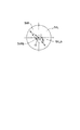
このようにして、上記光L7L,L7Rは、主反射面12で反射される際にそれぞれやや左上向きまたは右上向きに前方に向かって照射されることにより、図6に示すように、バルブ11の外形を構成するガラス管を回避しながら、シャッタ14の上方を通過することになる。従って、この光L7L,L7Rがバルブ11のガラス管により部分的にも遮断されるようなことはなく、副反射面51により反射された光が、投影レンズ13により前方に向かって確実に照射されることになり、前方に向かって照射される光量が増大することになる。
【0050】
このようにして、本発明実施形態による車両用灯具10乃至50によれば、バルブ11から出射して投影レンズ13に入射しない光L2,L4,L5,L6L,L6R,L7L,L7Rが、副反射面15,21,31,41,51により反射された後、主反射面11で反射されて投影レンズ13に入射するので、バルブ11からの光をより多く、投影レンズ13を介して前方に向かって照射することができ、その際シャッタ14の上方を通過させることにより、これらの光がシャッタ14によって遮断されることがないので、前方に向かって照射される光量が確実に増大され得ることになる。
【0051】
尚、上述した実施形態のうち、第一の実施形態では、副反射面15がバルブ11の発光中心の上側に配置され、また第二の実施形態では、副反射面21がバルブ11の発光中心の下側に配置されているが、これらを組み合わせて、バルブ11の発光中心の上側及び下側に、それぞれ副反射面15及び副反射面21を配置するようにしてもよい。これにより、前方に向かって照射される光の光量がより一層増大され得ることになる。
【0052】
【発明の効果】
以上述べたように、本発明によれば、光源から副反射面で反射された光は、副反射面の第二焦点に向かって集束され、その後主反射面で反射されて、投影レンズに入射し、同様に投影レンズにより集束され、前方に向かって照射され、所定の照射範囲を照明することになる。その際、副反射面の第一焦点が光源付近に配置されていることにより、副反射面で反射された光は、光源付近の第一焦点ではなく、光源から所定距離だけ離れた第二焦点に向かって集束するので、副反射面で反射された光がシャッタにより遮断されることなく、投影レンズに入射して、前方に向かって照射されるので、前方への照射光量が増大し、充分な光量が得られることになる。
このようにして、本発明によれば、簡単な構成により、投影レンズを大型化することなく、前方への光量を増大させるようにした、極めて優れた車両用灯具が提供され得る。
【図面の簡単な説明】
【図1】本発明による車両用灯具の第一の実施形態を示す概略側面図である。
【図2】本発明による車両用灯具の第二の実施形態を示す概略側面図である。
【図3】本発明による車両用灯具の第三の実施形態を示す概略側面図である。
【図4】本発明による車両用灯具の第四の実施形態を示す概略側面図である。
【図5】本発明による車両用灯具の第五の実施形態を示す概略側面図である。
【図6】図5の車両用灯具における副反射面による反射光を示す正面図である。
【図7】従来の車両用灯具の一例を示す概略側面図である。
【図8】従来の車両用灯具の他の例を示す概略側面図である。
【図9】図8の車両用灯具における副反射面による反射光のフィラメントへの入射状態を示す部分拡大側面図である。
【図10】図8の車両用灯具における副反射面による反射光の放電灯の放電部分への入射状態を示す部分拡大側面図である。
【符号の説明】
10,20,30,40,50 車両用灯具
11 バルブ
12 主反射面
13 投影レンズ
14 シャッタ
15,21,31,41,51 副反射面[0001]
BACKGROUND OF THE INVENTION
The present invention relates to a vehicular lamp that is used, for example, as a headlamp or an auxiliary headlamp provided at the front of an automobile.
[0002]
[Prior art]
2. Description of the Related Art Conventionally, automobile headlamps are configured, for example, as shown in FIG.
That is, in FIG. 7, a headlamp 1 includes a
[0003]
According to the headlamp 1 having such a configuration, the light emitted from the
[0004]
[Problems to be solved by the invention]
However, in such a headlamp 1, light is emitted from the
[0005]
By the way, as indicated by reference numeral 3 a in FIG. 7, it is conceivable that the peripheral edge of the
However, in this case, since the light reflected by the extension 3a has a large angle with respect to the optical axis, the diameter of the
[0006]
On the other hand, as shown in FIG. 8, instead of the extension 3a, a separate
However, in this case, when the
On the other hand, when the
[0007]
On the other hand, since the headlamp 1 is provided with the shutter 5 as described above, when the light from the
[0008]
In view of the above, an object of the present invention is to provide a vehicular lamp that can increase the amount of light forward with a simple configuration without increasing the size of a projection lens.
[0009]
According to the configuration of the present invention, the above object is achieved by a light source, a main reflection surface that reflects light from the light source forward, a projection lens that focuses light from the light source or the main reflection surface, and a projection lens from the light source. In a projector-type vehicular lamp including a shutter for cut-off disposed in the optical path to the light, the light that does not enter the projection lens among the light from the light source or the light reflected by the main reflection surface In the light path Provided at least either above or below the lamp optical axis in front of the light emission center of the light source, Equipped with a sub-reflecting surface consisting of an elliptical reflecting surface with the first focus near the light When the second focal point of the sub-reflecting surface is located above the lamp optical axis, the second focal point is disposed in front of the light emission center near the optical axis and located below the lamp optical axis. Is arranged behind the emission center near the optical axis. This is achieved by a vehicular lamp characterized in that
[0010]
In the vehicular lamp according to the present invention, preferably, the second focal point of the portion located above the optical axis of the sub-reflection surface is disposed in front of the light source.
[0011]
In the vehicular lamp according to the present invention, preferably, the second focal point of the portion located below the optical axis of the sub-reflecting surface is disposed behind the light source.
[0012]
In the vehicle lamp according to the present invention, preferably, the second focal point of the sub-reflecting surface is disposed below the light source.
[0013]
In the vehicular lamp according to the present invention, preferably, the sub-reflecting surface is divided into right and left, the second focal point of the left side portion is arranged on the left side of the light source, and the second focal point of the right side portion thereof. Is arranged to the right of the light source.
[0014]
In the vehicular lamp according to the present invention, preferably, the sub-reflecting surface is divided into right and left, the second focal point of the left part thereof is arranged at the lower left of the light source, and the second focal point of the right part thereof is , Arranged at the lower right of the light source.
[0015]
In the vehicular lamp according to the present invention, preferably, the sub-reflection surface is formed integrally with the main reflection surface.
[0016]
According to the above configuration, the light that is reflected from the light source directly or reflected by the main reflecting surface and is incident on the projection lens is converged by the projection lens and irradiated forward to illuminate a predetermined irradiation range. At this time, a part of the light incident on the projection lens is blocked by the shutter, so that desired orientation characteristics can be obtained such that the irradiation distance becomes longer on the oncoming lane side so as not to give the oncoming vehicle dazzling light.
[0017]
Furthermore, the light reflected by the sub-reflecting surface from the light source is focused toward the second focal point of the sub-reflecting surface, then reflected by the main reflecting surface, enters the projection lens, and is similarly focused by the projection lens, It irradiates forward and illuminates a predetermined irradiation range. At this time, since the first focal point of the sub-reflecting surface is arranged near the light source, the light reflected by the sub-reflecting surface is not the first focal point near the light source, but the second focal point separated from the light source by a predetermined distance. Since the light reflected by the sub-reflecting surface is incident on the projection lens without being blocked by the shutter and is irradiated toward the front, the amount of light applied to the front increases and is sufficient. A sufficient amount of light can be obtained.
[0018]
When the second focal point of the portion located above the optical axis of the sub-reflecting surface is disposed in front of the light source, the light reflected by the upper portion of the sub-reflecting surface and converged forward from the second focal point Is reflected slightly upward on the main reflecting surface, and then passes above the shutter and enters the projection lens. Thereby, since the light reflected by the sub-reflecting surface is not blocked by the shutter, the amount of light irradiated toward the front is surely increased.
[0019]
When the second focal point of the portion located below the optical axis of the sub-reflecting surface is disposed behind the light source, the light reflected by the lower portion of the sub-reflecting surface and converged forward from the second focal point Is reflected slightly upward on the main reflecting surface, and then passes above the shutter and enters the projection lens. Thereby, since the light reflected by the sub-reflecting surface is not blocked by the shutter, the amount of light irradiated toward the front is surely increased.
[0020]
When the second focal point of the sub-reflecting surface is disposed below the light source, the light reflected by the sub-reflecting surface and focused below the second focal point is reflected slightly upward on the main reflecting surface. As a result, the light passes above the shutter and enters the projection lens. Thereby, since the light reflected by the sub-reflecting surface is not blocked by the shutter, the amount of light irradiated toward the front is surely increased.
[0021]
The sub-reflecting surface is divided into right and left, the second focal point of the left side portion is arranged to the left of the light source, and the second focal point of the right side portion is arranged to the right of the light source. In this case, the light reflected by the left part of the sub-reflecting surface and focused to the left of the second focal point is reflected slightly leftward by the main reflecting surface, and is reflected by the right part of the sub-reflecting surface and reflected by the second focal point. The light focused more to the right is reflected slightly to the right by the main reflecting surface, and enters the projection lens while avoiding the glass tube that forms the outer shape of the light source. Thereby, since the light reflected by the sub-reflecting surface is not blocked by the shutter, the amount of light irradiated toward the front is surely increased.
[0022]
The sub-reflecting surface is divided into right and left, the second focal point of the left side portion is arranged at the lower left side of the light source, and the second focal point of the right side portion is arranged at the lower right side of the light source The light that is reflected by the left part of the sub-reflecting surface and converges to the lower left of the second focal point is reflected slightly downward to the left by the main reflecting surface, and is reflected by the right part of the sub-reflecting surface and from the second focal point. The light that converges to the lower right is reflected slightly downward to the right by the main reflecting surface, so that it avoids the glass tube that forms the outer shape of the light source, passes above the shutter, and enters the projection lens. . Thereby, since the light reflected by the sub-reflecting surface is not blocked by the shutter, the amount of light irradiated toward the front is surely increased.
[0023]
When the sub-reflecting surface is formed integrally with the main reflecting surface, the position of the sub-reflecting surface with respect to the main reflecting surface is maintained, so that the assembly is facilitated and the sub-reflecting surface with respect to the main reflecting surface is maintained. The positioning accuracy can be accurately maintained.
[0024]
In this way, according to the present invention, the sub-reflection surface is disposed in the optical path of the light from the light source or the light reflected by the main reflection surface and not incident on the projection lens, thereby being reflected by the sub-reflection surface. The focused light is focused toward the second focal point of the sub-reflecting surface, not the first focal point near the light source, and then reflected by the main reflecting surface and enters the projection lens. Therefore, the light reflected by the sub-reflecting surface is incident on the projection lens without being blocked by the shutter and is irradiated forward, so that the amount of light irradiated forward increases and a sufficient amount of light is obtained. It will be.
[0025]
DETAILED DESCRIPTION OF THE INVENTION
Hereinafter, preferred embodiments of the present invention will be described in detail with reference to FIGS. 1 to 6.
The embodiments described below are preferable specific examples of the present invention, and thus various technically preferable limitations are given. However, the scope of the present invention particularly limits the present invention in the following description. As long as there is no description of the effect, it is not restricted to these aspects.
[0026]
FIG. 1 shows a configuration of a first embodiment of a vehicular lamp according to the present invention.
In FIG. 1, a vehicular lamp 10 is a headlight of an automobile, and includes a bulb 11 as a light source, a
[0027]
The bulb 11 is a bulb configured as a discharge lamp that is generally used for a vehicle headlamp or an auxiliary headlamp. The bulb 11 is fixed and held by a socket 11a and is supplied with power.
[0028]
The
[0029]
The
[0030]
The
[0031]
The
Here, the elliptical reflection surface includes not only a spheroid and an elliptic cylinder but also a free-form surface based on an ellipse.
Further, the
[0032]
The vehicular lamp 10 according to the embodiment of the present invention is configured as described above, and the light L1 emitted from the light emission center of the bulb 11 is emitted directly or mainly when the bulb 11 is supplied with power from the socket 11a and emits light. After being reflected by the reflecting
[0033]
The light L2 emitted from the light emission center of the bulb 11 and reflected by the
Here, when the light L2 is reflected by the
[0034]
FIG. 2 shows a configuration of a second embodiment of the vehicular lamp according to the present invention.
In FIG. 2, the
[0035]
The
Further, the
[0036]
According to the
[0037]
The light L4 emitted from the light emission center of the bulb 11 and reflected by the
Here, when the light L4 is reflected by the main reflecting
[0038]
FIG. 3 shows the configuration of the third embodiment of the vehicular lamp according to the present invention.
In FIG. 3, the
[0039]
The
Further, the
[0040]
According to the
[0041]
The light L5 emitted from the light emission center of the bulb 11 and reflected by the
Here, when the light L5 is reflected by the main reflecting
[0042]
FIG. 4 shows the configuration of the fourth embodiment of the vehicular lamp according to the present invention.
In FIG. 4, the
[0043]
The
The left-side portion 41L of the
Further, the right portion 41R of the
Further, the
[0044]
According to the
[0045]
The light L6L emitted from the light emission center of the bulb 11 and reflected by the left portion 41L of the
On the other hand, the light L6R emitted from the light emission center of the bulb 11 and reflected by the right portion 41R of the
In this way, when the light L6L and L6R are reflected by the main reflecting
[0046]
FIG. 5 shows a configuration of a fifth embodiment of the vehicular lamp according to the present invention.
In FIG. 5, the vehicular lamp 50 has substantially the same configuration as the vehicular lamp shown in FIG. 1 except that a sub-reflecting surface 51 is provided instead of the
[0047]
The sub-reflecting surface 51 is an elliptical reflecting surface including left portions 51L and 51R divided from the center to the left and right.
The left-side portion 51L of the sub-reflecting surface 51 has the bulb 11 so that the first focal point 51La is located near the light emission center of the bulb 11, and the second focal point 51Lb is located on the lower left side of the emission center of the bulb 11. Are disposed in the region above and below the emission center.
Further, the right portion 51R of the sub-reflecting surface 51 has the bulb 11 so that the first focal point 51Ra is located near the emission center of the bulb 11 and the second focal point 51Rb is located on the lower right side of the emission center of the bulb 11. Are disposed in the region above and below the emission center.
Further, the sub-reflection surface 51, that is, the left portion 51L and the right portion 51R are preferably configured integrally with the main reflection surface 11. Thereby, positioning of the sub-reflection surface 51 with respect to the main reflection surface 11 can be performed easily and accurately.
[0048]
According to the vehicular lamp 50 having such a configuration, light (not shown) emitted from the light emission center of the bulb 11 is emitted directly or from the main reflecting
[0049]
The light L7L emitted from the light emission center of the bulb 11 and reflected by the left portion 51L of the sub-reflection surface 51 is focused toward the second focal point 51Lb, that is, the lower left of the light emission center of the bulb 11, and then the main reflection surface. 12, the light is incident on the
On the other hand, the light L7R emitted from the light emission center of the bulb 11 and reflected by the right portion 51R of the sub-reflection surface 51 is focused toward the second focal point 51Rb, that is, the lower right of the light emission center of the bulb 11, and then the main reflection surface. 12, the light is incident on the
In this way, when the light L7L and L7R are reflected by the main reflecting
[0050]
Thus, according to the vehicle lamps 10 to 50 according to the embodiment of the present invention, the light L2, L4, L5, L6L, L6R, L7L, and L7R that are emitted from the bulb 11 and are not incident on the
[0051]
Of the above-described embodiments, in the first embodiment, the
[0052]
【The invention's effect】
As described above, according to the present invention, the light reflected from the light source by the sub-reflecting surface is focused toward the second focal point of the sub-reflecting surface, and then reflected by the main reflecting surface to enter the projection lens. Similarly, the light is converged by the projection lens and irradiated toward the front to illuminate a predetermined irradiation range. At this time, since the first focal point of the sub-reflecting surface is arranged near the light source, the light reflected by the sub-reflecting surface is not the first focal point near the light source, but the second focal point separated from the light source by a predetermined distance. Since the light reflected by the sub-reflecting surface is incident on the projection lens without being blocked by the shutter and is irradiated toward the front, the amount of light applied to the front increases and is sufficient. A sufficient amount of light can be obtained.
As described above, according to the present invention, it is possible to provide an extremely excellent vehicular lamp with a simple configuration that increases the amount of light forward without increasing the size of the projection lens.
[Brief description of the drawings]
FIG. 1 is a schematic side view showing a first embodiment of a vehicular lamp according to the present invention.
FIG. 2 is a schematic side view showing a second embodiment of a vehicular lamp according to the present invention.
FIG. 3 is a schematic side view showing a third embodiment of a vehicular lamp according to the present invention.
FIG. 4 is a schematic side view showing a fourth embodiment of a vehicular lamp according to the present invention.
FIG. 5 is a schematic side view showing a fifth embodiment of a vehicular lamp according to the present invention.
6 is a front view showing light reflected by a sub-reflecting surface in the vehicular lamp of FIG. 5. FIG.
FIG. 7 is a schematic side view showing an example of a conventional vehicular lamp.
FIG. 8 is a schematic side view showing another example of a conventional vehicular lamp.
9 is a partially enlarged side view showing a state in which reflected light is incident on a filament by a sub-reflecting surface in the vehicular lamp of FIG. 8. FIG.
10 is a partial enlarged side view showing an incident state of light reflected by a sub-reflecting surface on the discharge portion of the discharge lamp in the vehicular lamp of FIG. 8. FIG.
[Explanation of symbols]
10, 20, 30, 40, 50 Vehicle lamp
11 Valve
12 Main reflective surface
13 Projection lens
14 Shutter
15, 21, 31, 41, 51 Sub-reflection surface
Claims (5)
上記光源からの光または主反射面で反射された光のうち、投影レンズに入射しない光の光路中にて、光源の発光中心より前方の灯具光軸の上方または下方の少なくともいずれかに設けられ、光源付近を第一焦点とする楕円反射面から成る副反射面を備え、
上記副反射面の第二焦点が、
上記灯具光軸より上方に位置する場合には、当該光軸上付近の上記発光中心より前方に配置され、上記灯具光軸より下方に位置する場合には、当該光軸上付近の上記発光中心より後方に配置されていることを特徴とする、車両用灯具。For a light source, a main reflection surface that reflects the light from the light source forward, a projection lens that focuses the light from the light source or the main reflection surface, and a cutoff placed in the light path from the light source to the projection lens A projector-type vehicular lamp including a shutter of
Of the light from the light source or the light reflected by the main reflecting surface, provided in at least either above or below the lamp optical axis in front of the light emission center of the light source in the optical path of the light not incident on the projection lens. A sub-reflecting surface composed of an elliptical reflecting surface with the light source and its vicinity as the first focal point ;
The second focal point of the sub-reflecting surface is
When located above the lamp optical axis, it is disposed in front of the light emission center near the optical axis, and when located below the lamp optical axis, the light emission center near the optical axis. A vehicular lamp characterized by being arranged further rearward .
Priority Applications (1)
| Application Number | Priority Date | Filing Date | Title |
|---|---|---|---|
| JP2000373647A JP4423527B2 (en) | 2000-12-08 | 2000-12-08 | Vehicle lighting |
Applications Claiming Priority (1)
| Application Number | Priority Date | Filing Date | Title |
|---|---|---|---|
| JP2000373647A JP4423527B2 (en) | 2000-12-08 | 2000-12-08 | Vehicle lighting |
Publications (2)
| Publication Number | Publication Date |
|---|---|
| JP2002175709A JP2002175709A (en) | 2002-06-21 |
| JP4423527B2 true JP4423527B2 (en) | 2010-03-03 |
Family
ID=18842992
Family Applications (1)
| Application Number | Title | Priority Date | Filing Date |
|---|---|---|---|
| JP2000373647A Expired - Fee Related JP4423527B2 (en) | 2000-12-08 | 2000-12-08 | Vehicle lighting |
Country Status (1)
| Country | Link |
|---|---|
| JP (1) | JP4423527B2 (en) |
Families Citing this family (3)
| Publication number | Priority date | Publication date | Assignee | Title |
|---|---|---|---|---|
| JP4008359B2 (en) | 2003-01-16 | 2007-11-14 | 株式会社小糸製作所 | Vehicle headlamp |
| JP4422005B2 (en) * | 2004-12-03 | 2010-02-24 | 株式会社小糸製作所 | Vehicle headlamp |
| US8485705B2 (en) | 2011-01-13 | 2013-07-16 | General Electric Company | Projector type headlamp of maximized light collecting efficiency |
-
2000
- 2000-12-08 JP JP2000373647A patent/JP4423527B2/en not_active Expired - Fee Related
Also Published As
| Publication number | Publication date |
|---|---|
| JP2002175709A (en) | 2002-06-21 |
Similar Documents
| Publication | Publication Date | Title |
|---|---|---|
| US6416210B1 (en) | Headlamp for a vehicle | |
| US20070171665A1 (en) | High-intensity zone LED projector | |
| JP5544248B2 (en) | Vehicle headlamp | |
| JP2001195910A (en) | Headlight for vehicle | |
| JP4257675B2 (en) | Vehicle headlamp | |
| US8186861B2 (en) | Vehicular headlamp | |
| JP4945653B2 (en) | Vehicle headlamp | |
| JP4423527B2 (en) | Vehicle lighting | |
| JP4154651B2 (en) | Lamp and projection lens | |
| JP2008135247A (en) | Vehicle headlamp | |
| JP4453495B2 (en) | Vehicle lighting | |
| JP4666266B2 (en) | Vehicle headlamp | |
| JP4758753B2 (en) | Vehicle headlamp | |
| JP4666160B2 (en) | Vehicle lighting | |
| JP2007258000A (en) | Vehicle headlamp | |
| JP4960747B2 (en) | Vehicle headlamp | |
| JP4587047B2 (en) | Vehicle lighting | |
| JP4459095B2 (en) | Bending lamp for vehicles | |
| JP4315342B2 (en) | Vehicle headlamp | |
| JP4189807B2 (en) | Vehicle lighting | |
| JP4608645B2 (en) | Vehicle lighting | |
| JP5412314B2 (en) | Vehicle headlamp | |
| JP2005317465A (en) | Vehicular headlight | |
| JPH05334902A (en) | Projector lamp for vehicle | |
| JP2000133024A (en) | Projector-type headlamp |
Legal Events
| Date | Code | Title | Description |
|---|---|---|---|
| A621 | Written request for application examination |
Free format text: JAPANESE INTERMEDIATE CODE: A621 Effective date: 20071203 |
|
| A977 | Report on retrieval |
Free format text: JAPANESE INTERMEDIATE CODE: A971007 Effective date: 20090812 |
|
| A131 | Notification of reasons for refusal |
Free format text: JAPANESE INTERMEDIATE CODE: A131 Effective date: 20090825 |
|
| A521 | Written amendment |
Free format text: JAPANESE INTERMEDIATE CODE: A523 Effective date: 20091026 |
|
| TRDD | Decision of grant or rejection written | ||
| A01 | Written decision to grant a patent or to grant a registration (utility model) |
Free format text: JAPANESE INTERMEDIATE CODE: A01 Effective date: 20091124 |
|
| A01 | Written decision to grant a patent or to grant a registration (utility model) |
Free format text: JAPANESE INTERMEDIATE CODE: A01 |
|
| A61 | First payment of annual fees (during grant procedure) |
Free format text: JAPANESE INTERMEDIATE CODE: A61 Effective date: 20091125 |
|
| R150 | Certificate of patent or registration of utility model |
Free format text: JAPANESE INTERMEDIATE CODE: R150 Ref document number: 4423527 Country of ref document: JP Free format text: JAPANESE INTERMEDIATE CODE: R150 |
|
| FPAY | Renewal fee payment (event date is renewal date of database) |
Free format text: PAYMENT UNTIL: 20121218 Year of fee payment: 3 |
|
| FPAY | Renewal fee payment (event date is renewal date of database) |
Free format text: PAYMENT UNTIL: 20121218 Year of fee payment: 3 |
|
| FPAY | Renewal fee payment (event date is renewal date of database) |
Free format text: PAYMENT UNTIL: 20131218 Year of fee payment: 4 |
|
| R250 | Receipt of annual fees |
Free format text: JAPANESE INTERMEDIATE CODE: R250 |
|
| R250 | Receipt of annual fees |
Free format text: JAPANESE INTERMEDIATE CODE: R250 |
|
| R250 | Receipt of annual fees |
Free format text: JAPANESE INTERMEDIATE CODE: R250 |
|
| R250 | Receipt of annual fees |
Free format text: JAPANESE INTERMEDIATE CODE: R250 |
|
| R250 | Receipt of annual fees |
Free format text: JAPANESE INTERMEDIATE CODE: R250 |
|
| R250 | Receipt of annual fees |
Free format text: JAPANESE INTERMEDIATE CODE: R250 |
|
| LAPS | Cancellation because of no payment of annual fees |