JP4423251B2 - Wireless receiver - Google Patents
Wireless receiver Download PDFInfo
- Publication number
- JP4423251B2 JP4423251B2 JP2005298866A JP2005298866A JP4423251B2 JP 4423251 B2 JP4423251 B2 JP 4423251B2 JP 2005298866 A JP2005298866 A JP 2005298866A JP 2005298866 A JP2005298866 A JP 2005298866A JP 4423251 B2 JP4423251 B2 JP 4423251B2
- Authority
- JP
- Japan
- Prior art keywords
- signal
- mixer
- path
- radio
- intermediate frequency
- Prior art date
- Legal status (The legal status is an assumption and is not a legal conclusion. Google has not performed a legal analysis and makes no representation as to the accuracy of the status listed.)
- Expired - Fee Related
Links
Images


Classifications
-
- H—ELECTRICITY
- H04—ELECTRIC COMMUNICATION TECHNIQUE
- H04B—TRANSMISSION
- H04B1/00—Details of transmission systems, not covered by a single one of groups H04B3/00 - H04B13/00; Details of transmission systems not characterised by the medium used for transmission
- H04B1/06—Receivers
- H04B1/10—Means associated with receiver for limiting or suppressing noise or interference
- H04B1/109—Means associated with receiver for limiting or suppressing noise or interference by improving strong signal performance of the receiver when strong unwanted signals are present at the receiver input
Landscapes
- Engineering & Computer Science (AREA)
- Computer Networks & Wireless Communication (AREA)
- Signal Processing (AREA)
- Superheterodyne Receivers (AREA)
Description
この発明は、無線受信装置に関し、例えば、放送波をマイクロ波帯で無線送信した信号を受信するマイクロ波帯無線受信装置に関する。 The present invention relates to a radio reception apparatus, for example, a microwave band radio reception apparatus that receives a signal obtained by wirelessly transmitting a broadcast wave in a microwave band.
一般に、無線受信装置においては、受信した無線変調信号(以下、RF信号という)と、受信装置内で生成される局部発振信号(以下、LO信号という)とから、中間周波数信号(以下、IF信号という)を生成するミキサが、用いられている。 In general, in a radio reception apparatus, an intermediate frequency signal (hereinafter referred to as an IF signal) is generated from a received radio modulation signal (hereinafter referred to as an RF signal) and a local oscillation signal (hereinafter referred to as an LO signal) generated in the reception apparatus. Is used.
ミキサに入力されるLO信号の電力と動作バイアスは、変換利得、雑音特性、低歪み等の観点から良好なIF信号を復調できるように適切な点が選ばれる。LO信号の電力は一定で、RF信号の電力に比べて十分大きくなっているのが一般的である。従って、ミキサの動作バイアス電流は、LO信号の電力に依存した値となり、受信したRF信号電力にはほとんど依存しないので、ほぼ一定の値となっている。 The power and operating bias of the LO signal input to the mixer are appropriately selected so that a good IF signal can be demodulated from the viewpoint of conversion gain, noise characteristics, low distortion, and the like. In general, the power of the LO signal is constant and is sufficiently larger than the power of the RF signal. Therefore, the operation bias current of the mixer is a value that depends on the power of the LO signal and is almost independent of the received RF signal power, and is therefore a substantially constant value.
近年では、10GHz以上のマイクロ波・ミリ波帯という高い周波数帯を用いた無線装置の開発が盛んになっており、以下に示すような無線受信機および無線受信方法が提案されている(例えば、特開2003−258655号公報:特許文献1参照)。 In recent years, wireless devices using a high frequency band such as a microwave / millimeter wave band of 10 GHz or more have been actively developed, and wireless receivers and wireless reception methods as described below have been proposed (for example, JP, 2003-258655, A: refer to patent documents 1).
図10に、提案されている無線受信機900の構成および周波数配置を示す。受信機900は、送信機から送信された無線多重信号930をアンテナ901で受信する。この無線多重信号は、第1の局部発振信号930c(周波数:fLO1)と第1の無線変調信号930aとが合成されたものになっている。この第1の無線変調信号930aは、第1の局部発振信号930cと第1の中間周波数信号932a(IF1信号、周波数:fIF1)が乗積されたものであり、周波数は、fLO1+fIF1である。
FIG. 10 shows the configuration and frequency arrangement of the proposed
受信した無線多重信号930は、フィルタ902で不要波が除去され、増幅器903で増幅される。次に、ミキサ905を用いて、増幅された無線信号と、受信機内部の局部発振器904から発生する第2の局部発振信号(周波数:fLO2)とを乗積し、ダウンコンバートすることによって、第1の局部発振信号成分の信号931c(周波数:fLO1−fLO2)と第1の無線変調信号成分の信号931a(周波数:fLO1+fIF1−fLO2)が生成される。
The received radio multiplexed signal 930 is subjected to the removal of unnecessary waves by the
次に、増幅器906により増幅された後、分配器907で分配され、一方は、第1の局部発振信号成分の信号931cのみが通過できるフィルタ908を介し、増幅器910によって増幅された後、ミキサ911に入力され、もう一方は、第1の無線変調信号成分の信号931aのみが通過するフィルタ909を介して、ミキサ911に入力される。
Next, after being amplified by the amplifier 906 and distributed by the
ミキサ911では、第1の局部発振信号成分の信号931cと第1の無線変調信号成分の信号931aを乗積して、ダウンコンバートすることによって、IF1信号932aが復調される。つまり、下記のような式によって表現される。
In the
(fLO1+fIF1−fLO2)―(fLO1−fLO2)=fIF1 (FLO1 + fIF1-fLO2)-(fLO1-fLO2) = fIF1
この方法では、第1の局部発振信号および第2の局部発振信号の周波数のゆらぎや位相雑音は、IF1信号の復調時に、キャンセルされるので、高性能な発振器は不要となり、その結果、製造コストを低くすることができるとしている。また、増幅器910によって、第1の局部発振信号成分の信号931cは、増幅されるので、LO電力として十分なレベルの信号が、ミキサ911に供給でき、その結果、復調感度を大きくできるとしている。
しかしながら、上記無線システムでは、無線多重信号930の受信電力に比例して、ミキサに入力されるLO電力も変化してしまう。受信電力が小さい場合には、LO電力は小さく、逆に、受信電力が大きい場合には、LO電力は大きくなる。このため、従来のミキサを用いた場合には、ミキサの動作バイアス電流は、無線多重信号930の受信電力によって大きく変化してしまった。その結果、地上デジタルやBS/CSといったテレビ放送波を伝送した場合には、伝送距離を短くし、受信電力が大きくなったときに、ミキサの動作状態(動作バイアス)が変化してしまい、受信C/N(キャリア対雑音比)が劣化したり、大電流が生じてミキサが破壊されたりしてしまう場合があった。 However, in the above wireless system, the LO power input to the mixer also changes in proportion to the received power of the wireless multiplexed signal 930. When the received power is small, the LO power is small. Conversely, when the received power is large, the LO power is large. For this reason, when a conventional mixer is used, the operation bias current of the mixer greatly varies depending on the reception power of the radio multiplexed signal 930. As a result, when a television broadcast wave such as terrestrial digital or BS / CS is transmitted, when the transmission distance is shortened and the reception power is increased, the operation state (operation bias) of the mixer is changed and reception is performed. In some cases, C / N (carrier-to-noise ratio) deteriorates, or a large current is generated and the mixer is destroyed.
また、受信電力が大きくても、上記問題が生じないように、ミキサの動作バイアスを設定すると、受信電力が小さい場合には、ミキサが動作せず、ミキサの出力が小さくなって、受信C/Nが確保できず、伝送距離を長くすることができなかった。 In addition, when the operation bias of the mixer is set so that the above problem does not occur even when the reception power is large, when the reception power is small, the mixer does not operate and the output of the mixer decreases, and the reception C / N could not be secured, and the transmission distance could not be increased.
つまり、このような無線システムでは、ミキサのダイナミックレンジが狭くなり、上記無線システムにおいて、広い範囲の伝送距離で安定した受信C/N特性や、映像特性を得ることができなかった。 That is, in such a wireless system, the dynamic range of the mixer is narrowed, and in the wireless system, stable reception C / N characteristics and video characteristics cannot be obtained over a wide transmission distance.
そこで、この発明の課題は、同時に送信された第1の信号と第2の信号を乗積しダウンコンバードする無線受信装置において、ミキサのダイナミックレンジを広くし、広い範囲の伝送距離で安定した映像特性を得ることができる無線受信装置を提供することにある。 SUMMARY OF THE INVENTION Accordingly, an object of the present invention is to increase the dynamic range of a mixer in a radio receiving apparatus that multiplies a first signal and a second signal transmitted at the same time and down-converts them, and stabilizes video over a wide transmission distance. An object of the present invention is to provide a radio receiving apparatus capable of obtaining characteristics.
上記課題を解決するため、この発明の無線受信装置は、
第1の信号と第2の信号とを含む無線多重信号を受信し、上記第1の信号と上記第2の信号とをミキサにより乗積することで上記無線多重信号をダウンコンバートして、中間周波数信号を生成するダウンコンバータを備え、
上記ミキサは、上記第1の信号または上記第2の信号の少なくともいずれか一方の信号強度に応じて、上記ミキサの動作バイアスを制御する制御部を有し、
上記ミキサは、上記無線多重信号をベースに受けて入力変調信号を出力するトランジスタを有し、
上記制御部は、上記無線多重信号の強度が大きいとき、上記トランジスタのベース電圧を低くする一方、上記無線多重信号の強度が小さいとき、上記トランジスタのベース電圧を高くするように制御することを特徴としている。
In order to solve the above problems, a wireless reception device of the present invention provides:
A radio multiplex signal including a first signal and a second signal is received, and the radio multiplex signal is down-converted by multiplying the first signal and the second signal by a mixer, and intermediate It has a down converter that generates a frequency signal,
The mixer, depending on at least one of signal strength of said first signal or said second signal, have a control unit for controlling the operating bias of the mixer,
The mixer has a transistor that receives the radio multiplexed signal as a base and outputs an input modulation signal,
The control unit controls the base voltage of the transistor to be lowered when the strength of the wireless multiplex signal is large, while increasing the base voltage of the transistor when the strength of the wireless multiplex signal is small. It is said.
この発明の無線受信装置によれば、上記ミキサは、上記第1の信号または上記第2の信号の少なくともいずれか一方の信号強度に応じて、上記ミキサの動作バイアスを制御する制御部を有するので、受信した上記無線多重信号の強度が大きくなっても、上記ミキサの動作バイアス電流が過剰にならないように制御できるので、上記ミキサが破壊されることを防ぐことができる。また、受信した上記無線多重信号の信号強度が大きい場合あるいは小さい場合でも、それに応じて、上記ミキサが適切に動作するように動作バイアスを制御できるので、広い範囲の伝送距離において、良好な受信C/Nを確保することができる。 According to the wireless reception device of the present invention, the mixer has a control unit that controls the operation bias of the mixer according to the signal strength of at least one of the first signal and the second signal. Even if the intensity of the received radio multiplexed signal increases, the mixer can be controlled so that the operation bias current does not become excessive, so that the mixer can be prevented from being destroyed. Even when the signal strength of the received radio multiplexed signal is large or small, the operation bias can be controlled so that the mixer operates properly accordingly, so that a good reception C can be achieved over a wide transmission distance. / N can be secured.
また、この発明の無線受信装置は、
第1の信号と第2の信号とを含む無線多重信号を受信し、受信した無線多重信号を局部発振信号によりダウンコンバートして、第1の中間周波数信号を生成する第1のダウンコンバータと、
上記第1の中間周波数信号に含まれる上記第1の信号と上記第2の信号とをミキサにより乗積することで、上記第1の中間周波数信号をダウンコンバートして、第2の中間周波数信号を生成する第2のダウンコンバータと
を備え、
上記ミキサは、上記第1の信号または上記第2の信号の少なくともいずれか一方の信号強度に応じて、上記ミキサの動作バイアスを制御する制御部を有し、
上記ミキサは、上記無線多重信号をベースに受けて上記第2の中間周波数信号を出力するトランジスタを有し、
上記制御部は、上記無線多重信号の強度が大きいとき、上記トランジスタのベース電圧を低くする一方、上記無線多重信号の強度が小さいとき、上記トランジスタのベース電圧を高くするように制御することを特徴としている。
In addition, the wireless receiver of the present invention is
A first down converter that receives a radio multiplexed signal including a first signal and a second signal, down-converts the received radio multiplexed signal with a local oscillation signal, and generates a first intermediate frequency signal;
The first intermediate frequency signal is down-converted by multiplying the first signal and the second signal included in the first intermediate frequency signal by a mixer, thereby obtaining a second intermediate frequency signal. And a second down converter for generating
The mixer, depending on at least one of signal strength of said first signal or said second signal, have a control unit for controlling the operating bias of the mixer,
The mixer has a transistor that receives the radio multiplexed signal as a base and outputs the second intermediate frequency signal,
The control unit controls the base voltage of the transistor to be lowered when the strength of the wireless multiplex signal is large, while increasing the base voltage of the transistor when the strength of the wireless multiplex signal is small. It is said.
ここで、上記制御部が応じる上記第1の信号または上記第2の信号は、上記無線多重信号および上記第1の中間周波数信号の双方に含まれるが、上記制御部は、どちらの信号強度に応じるものでもよい。 Here, the first signal or the second signal to which the control unit responds is included in both the radio multiplexed signal and the first intermediate frequency signal. You may respond.
この発明の無線受信装置によれば、上記第1のダウンコンバータと上記第2のダウンコンバータとを備えるので、上記第1の信号と上記第2の信号は、上記第1のダウンコンバータによって、低周波側に周波数変換されるので、上記第2のダウンコンバータは安価な部品で構成することが可能となる。また、受信した信号強度が大きいときに、上記第2のダウンコンバータで、上記ミキサの動作バイアス電流が過剰にならないように制御できるので、上記ミキサ自体が破壊されることを防ぐことができる。また、受信した無線多重信号の信号強度が大きい場合あるいは小さい場合でも、それに応じて上記ミキサが適切に動作するように動作バイアスを制御できるので、広い範囲の伝送距離において、良好な受信C/Nを確保することができる。 According to the radio reception apparatus of the present invention, since the first down converter and the second down converter are provided, the first signal and the second signal are reduced by the first down converter. Since the frequency conversion is performed on the frequency side, the second down converter can be configured with inexpensive components. Also, when the received signal strength is high, the second down converter can be controlled so that the operation bias current of the mixer does not become excessive, so that the mixer itself can be prevented from being destroyed. Further, even when the signal strength of the received radio multiplexed signal is large or small, the operation bias can be controlled so that the mixer operates appropriately in accordance with the signal strength. Therefore, a good reception C / N can be obtained over a wide transmission distance. Can be secured.
また、一実施形態の無線受信装置では、上記第2のダウンコンバータは、第1の経路と、第2の経路と、上記第1の中間周波数信号を上記第1の経路と上記第2の経路とに分配する分配器とを有し、
上記第1の経路は、上記分配器からの上記第1の中間周波数信号を上記ミキサに伝送し、
上記第2の経路は、上記第1の中間周波数信号から上記第2の信号を抽出するフィルタと、このフィルタから抽出された上記第2の信号を増幅する増幅器とを有すると共に、この増幅された第2の信号を上記ミキサに伝送する。
In one embodiment, the second down-converter includes a first path, a second path, the first intermediate frequency signal, the first path, and the second path. And a distributor for distributing to
The first path transmits the first intermediate frequency signal from the distributor to the mixer;
The second path includes a filter that extracts the second signal from the first intermediate frequency signal, and an amplifier that amplifies the second signal extracted from the filter. A second signal is transmitted to the mixer.
この実施形態の無線受信装置によれば、上記第2の経路は、上記第1の中間周波数信号から上記第2の信号を抽出するフィルタと、このフィルタから抽出された上記第2の信号を増幅する増幅器とを有し、この増幅された第2の信号を上記ミキサに伝送するので、上記第2のダウンコンバータの上記ミキサに入力されるLO電力となる上記第2の信号を増幅することができるので、上記ミキサの復調感度を上げることができる。そのため、良好な受信C/Nが確保できる伝送距離をさらに長くすることができる。 According to the wireless receiver of this embodiment, the second path amplifies the filter that extracts the second signal from the first intermediate frequency signal, and the second signal extracted from the filter. And amplifying the second signal as LO power input to the mixer of the second down converter. Therefore, the demodulation sensitivity of the mixer can be increased. Therefore, it is possible to further increase the transmission distance that can ensure good reception C / N.
また、一実施形態の無線受信装置では、上記第2のダウンコンバータは、第1の経路と、第2の経路と、上記第1の中間周波数信号を上記第1の経路と上記第2の経路とに分配する分配器とを有し、
上記第1の経路は、上記第1の中間周波数信号を増幅する増幅器を有すると共に、この増幅された上記第1の中間周波数信号を上記ミキサに伝送し、
上記第2の経路は、上記第1の中間周波数信号から上記第2の信号を抽出するフィルタと、このフィルタから抽出された上記第2の信号を増幅する増幅器とを有すると共に、この増幅された第2の信号を上記ミキサに伝送する。
In one embodiment, the second down-converter includes a first path, a second path, the first intermediate frequency signal, the first path, and the second path. And a distributor for distributing to
The first path includes an amplifier that amplifies the first intermediate frequency signal, and transmits the amplified first intermediate frequency signal to the mixer.
The second path includes a filter that extracts the second signal from the first intermediate frequency signal, and an amplifier that amplifies the second signal extracted from the filter. A second signal is transmitted to the mixer.
この実施形態の無線受信装置によれば、上記第1の経路および上記第2の経路の両方に上記増幅器を有するので、上記増幅器のアイソレーション作用により、ループ発振が起こることを防ぐことができる。 According to the wireless receiver of this embodiment, since the amplifier is provided in both the first path and the second path, it is possible to prevent loop oscillation from occurring due to the isolation action of the amplifier.
また、一実施形態の無線受信装置では、上記第2のダウンコンバータは、第1の経路と、第2の経路と、第3の経路と、上記第1の中間周波数信号を上記第1の経路と上記第2の経路と上記第3の経路とに分配する分配器とを有し、
上記第1の経路は、上記第1の中間周波数信号から所定帯域の信号を抽出するフィルタを有すると共に、この所定帯域の信号を第1の上記ミキサに伝送し、
上記第2の経路は、上記第1の中間周波数信号から所定帯域の信号を抽出するフィルタを有すると共に、この所定帯域の信号を第2の上記ミキサに伝送し、
上記第3の経路は、上記第1の中間周波数信号から上記第2の信号を抽出するフィルタと、このフィルタから抽出された上記第2の信号を増幅する増幅器とを有すると共に、この増幅された第2の信号を上記第1のミキサおよび上記第2のミキサに伝送する。
In one embodiment, the second down converter includes a first path, a second path, a third path, and the first intermediate frequency signal as the first path. And a distributor for distributing the second path and the third path,
The first path includes a filter that extracts a signal in a predetermined band from the first intermediate frequency signal, and transmits the signal in the predetermined band to the first mixer.
The second path has a filter that extracts a signal of a predetermined band from the first intermediate frequency signal, and transmits the signal of the predetermined band to the second mixer,
The third path includes a filter that extracts the second signal from the first intermediate frequency signal, and an amplifier that amplifies the second signal extracted from the filter, and the amplified signal is amplified. A second signal is transmitted to the first mixer and the second mixer.
この実施形態の無線受信装置によれば、上記第1の経路および上記第2の経路の両方に上記フィルタを有するので、上記第1の経路および上記第2の経路のそれぞれによって、上記第1の中間周波数信号を帯域分割できて、異なった帯域で、上記第2のダウンコンバートを複数同時にかつ狭い帯域で行うことにより、C/N劣化や高調波ひずみ特性劣化を小さくすることができる。 According to the wireless reception device of this embodiment, since the filter is included in both the first route and the second route, the first route and the second route respectively include the first route and the second route. By dividing the intermediate frequency signal into bands and performing the second down-conversion in a plurality of different bands simultaneously and in a narrow band, C / N degradation and harmonic distortion characteristic degradation can be reduced.
また、一実施形態の無線受信装置では、上記ミキサは、マイクロ波トランジスタを有する。 In one embodiment, the mixer has a microwave transistor.
この実施形態の無線受信装置によれば、上記ミキサは、マイクロ波トランジスタを有するので、バイアス制御によってミキサの周波数変換特性を制御することができるとともに、入力・出力間のアイソレーションが得られることも加わり、出力信号に入力信号漏れが極めて少さく、出力信号には不要波成分や、信号のC/N劣化や高調波ひずみ特性劣化が小さい良質の周波数変換が可能となる。 According to the wireless receiver of this embodiment, since the mixer has a microwave transistor, the frequency conversion characteristics of the mixer can be controlled by bias control, and isolation between the input and the output can be obtained. In addition, the input signal leakage is extremely small in the output signal, and the output signal can be subjected to high-quality frequency conversion in which unnecessary wave components, signal C / N deterioration and harmonic distortion characteristic deterioration are small.
また、一実施形態の無線受信装置では、上記ミキサは、上記第1の信号および上記第2の信号を上記マイクロ波トランジスタのベースに抽入するベース注入型ミキサである。 In one embodiment, the mixer is a base injection mixer that draws the first signal and the second signal into the base of the microwave transistor.
この実施形態の無線受信装置によれば、上記ミキサは、上記第1の信号および上記第2の信号をベース側から入力する構成であるため、増幅機能も有することにより、上記ミキサの入力ポートは、少ない信号強度で、周波数変換することができる。したがって、伝送距離を長くすることができる。 According to the wireless reception device of this embodiment, the mixer is configured to input the first signal and the second signal from the base side, and therefore has an amplification function, so that the input port of the mixer is The frequency can be converted with a small signal intensity. Therefore, the transmission distance can be increased.
また、一実施形態の無線受信装置では、上記制御部は、抵抗器を有し、この抵抗器は、上記ミキサから生じる電流を制御することによって、上記ミキサの動作バイアスを制御する。 In one embodiment, the control unit includes a resistor, and the resistor controls an operation bias of the mixer by controlling a current generated from the mixer.
この実施形態の無線受信装置によれば、上記制御部は、上記抵抗器を有するので、非常に簡単な構成で上記ミキサの動作バイアスを制御できる。したがって、上記ミキサの小型化および低コスト化が可能となる。 According to the wireless reception device of this embodiment, since the control unit includes the resistor, the operation bias of the mixer can be controlled with a very simple configuration. Therefore, the mixer can be reduced in size and cost.
また、一実施形態の無線受信装置では、上記制御部は、抵抗器を有し、この抵抗器は、10kΩ以上であり、上記マイクロ波トランジスタのベース端子に接続され、
この抵抗器は、上記ミキサから生じる電流を制御することによって、上記ミキサの動作バイアスを制御する。
In one embodiment, the control unit includes a resistor, the resistor is 10 kΩ or more, and is connected to the base terminal of the microwave transistor,
The resistor controls the operational bias of the mixer by controlling the current generated from the mixer.
この実施形態の無線受信装置によれば、上記制御部は、上記抵抗器を有するので、非常に簡単な構成で上記ミキサの動作バイアスを制御できる。したがって、上記ミキサの小型化および低コスト化が可能となる。 According to the wireless reception device of this embodiment, since the control unit includes the resistor, the operation bias of the mixer can be controlled with a very simple configuration. Therefore, the mixer can be reduced in size and cost.
また、上記トランジスタに入力される信号が大きくなっても、上記トランジスタのベース端子に印加されるバイアス電圧が、上記抵抗器による電圧降下によって、低下して、過大電流による上記トランジスタの破壊を防ぐことができる。また、バイアス電圧が低下することにより、上記ミキサの増幅機能も低下するので、上記ミキサが歪み難く、C/N劣化や高調波ひずみによる特性劣化を防ぐことができる。 In addition, even when the signal input to the transistor increases, the bias voltage applied to the base terminal of the transistor decreases due to a voltage drop due to the resistor, thereby preventing destruction of the transistor due to excessive current. Can do. Further, since the amplifying function of the mixer is lowered due to the lowering of the bias voltage, the mixer is hardly distorted, and characteristic deterioration due to C / N degradation and harmonic distortion can be prevented.
この発明の無線受信装置によれば、受信した無線多重信号の強度が大きくなっても、ミキサの動作バイアス電流が過剰にならないように制御できるので、ミキサが破壊されることを防ぐことができる。また、受信した無線多重信号の信号強度が大きい場合あるいは小さい場合でも、それに応じてミキサが適切に動作するように動作バイアスを制御できるので、広い範囲の伝送距離において、良好な受信C/Nを確保することができる。 According to the wireless receiver of the present invention, even if the intensity of the received wireless multiplexed signal is increased, the mixer can be controlled so that the operation bias current does not become excessive, so that the mixer can be prevented from being destroyed. In addition, even when the signal strength of the received radio multiplexed signal is large or small, the operation bias can be controlled so that the mixer operates properly accordingly, so that a good reception C / N can be obtained over a wide range of transmission distance. Can be secured.
以下、この発明を図示の実施の形態により詳細に説明する。 Hereinafter, the present invention will be described in detail with reference to the illustrated embodiments.
(第1の実施形態)
図1は、本発明の第1の実施のマイクロ波帯無線通信システムの詳細構成図を示している。また、図2Aは、送信装置の入力信号5eの周波数配置図を示す。図2Bは、第1のIF多重信号71dの周波数配置図を示す。図2Cは、送信装置の出力信号である無線多重信号72の周波数配置図を示す。
(First embodiment)
FIG. 1 shows a detailed configuration diagram of a microwave band wireless communication system according to a first embodiment of the present invention. FIG. 2A shows a frequency arrangement diagram of the
図1に示すように、マイクロ波帯無線送信装置の一例としてのミリ帯無線送信装置9は、周波数配列部5と、中間周波数変換手段の一例として第1の周波数変換回路2aと、基準信号源2cと、多重信号生成手段の一例としての基準信号付加回路2dと、送信側周波数変換手段の一例としてのミリ波周波数変換回路3aとを備えている。
As shown in FIG. 1, a millimeter band radio transmission apparatus 9 as an example of a microwave band radio transmission apparatus includes a frequency array unit 5, a first frequency conversion circuit 2a as an example of an intermediate frequency conversion means, and a reference signal source. 2c, a reference signal addition circuit 2d as an example of a multiplexed signal generation unit, and a millimeter wave
上記周波数配列部5では、地上波放送用アンテナ1aからの入力変調波信号5aおよび衛星放送用アンテナ1bからの入力変調波信号5bは、夫々、増幅器51、52で、夫々の入力変調信号5a、5bの総電力レベルが略等しくなるように調整され、混合器53で電力合成され、かつ周波数配列され、一系列の信号5e(周波数:fIF1e)が生成される。
In the frequency arrangement unit 5, the input modulated
ここで、入力変調信号5aと入力変調信号5bが同じ周波数帯であれば、直接電力合成することはできないため、どちらかの変調信号が周波数変換され、夫々の信号が電力合成されて、一系列の信号5e(fIF1e)が生成される。
Here, if the
この実施形態では、入力変調信号5a、5bは、周波数帯が異なっているため、そのまま電力合成器53で合成している。さらに、夫々の入力変調信号5a、5bの総電力レベルが略等しくなるように調整したが、入力変調信号波の品質に応じて、電力レベルは異なったレベルで電力合成しても構わない。
In this embodiment, the
次に、上記周波数軸上に配列された一系列の信号5e(fIF1e)は、増幅器20で、適当なレベルまで増幅および調整され、周波数混合器21に入力され、第1の周波数変換がなされる。周波数変換された第1のIF信号71aは、フィルタ22により片側波帯信号のみを通過させ、増幅器(や適宜アッテネータ組み合わせ)23で、適正レベルまで調整された後、一方で適正レベルに調整された基準信号71c(周波数:fLO1)が、電力合成器24aにより付加され、中間周波数多重信号(周波数配列信号)71dが生成される。以後、第1のIF多重信波信号71dと記す。
Next, the series of
ここで、周波数fLO1を有した基準信号源2cは、電力分配器24bで2分配され、一方の信号は周波数変換器21の局部発振信号源として入力される。また電力分配された信号は、レベル制御器95に入力され、後述する適当なレベル制御された後、基準信号71cとして、電力合成器24aに入力され、前記第1のIF信号71aと電力合成され、第1のIF多重信波信号71dが生成される。このような構成により、第1のIF信号71aが、増幅器23等のレベル制御手段でレベル制御された後に、基準信号71cを付加するため、増幅器23が、レベルの大きい基準信号71cにより歪むことがなく、レベルの小さい上記第1のIF信号71a信号のみを、効率よく線形に増幅することができる。
Here, the reference signal source 2c having the frequency fLO1 is divided into two by the power distributor 24b, and one signal is input as a local oscillation signal source of the
加えて、第1のIF多重信波信号71d中の第1のIF信号71aの電力レベルと基準信号波71cの電力レベルと、夫々の電力レベル配分比を、第1のIF信号71aは、増幅器(や適宜アッテネータ組み合わせ)23により、また、基準信号71cは、レベル制御器95により、それぞれ独立に制御することにより、送信側の周波数変換・送信回路3aをフルパワーで、より線形に駆動させることできる。
In addition, the power level of the first IF
加えて、あらかじめ送信側で、第1のIF多重信号71dの生成段階で、受信感度の高い最適の電力配分比に、(前記第1のIF信号71aの電力)/(基準信号71cの電力)の設定を、適当な比率に設定することが必要である。これは、周波数変換効率(受信感度)を高め、無線伝送距離を拡大することを可能とする。
In addition, on the transmission side, at the generation stage of the first IF multiplexed
なお、この実施形態の一例として、レベル制御器95や、増幅器に使用されているレベル制御部23のアッテネータは、チップ部品の抵抗器でT型アッテネータやπ型アッテネータにより構成されている。また、上記基準信号付加回路2d中の電力合成器24aおよび電力分配器24bは、出力ポートが、互いにアイソレーション特性を有したウィルキンソン型合成器が望ましい。これにより各出力ポートに漏れこんでくる信号を抑圧し、各機能回路を正常に動作させることができる。詳細には、該ウィルキンソン型の周波数合成器24aおよび周波数分配器24bと増幅器23によって、上記第1のIF信号71aが基準信号付加回路2d側への信号の漏れ込みや、付加された基準信号71cが、周波数ミキサ21への逆流を防ぐことが可能となる。
As an example of this embodiment, the attenuator of the level controller 95 and the
ここで、該周波数変換においては、望ましくは下側波帯信号を用いることによって、周波数変換後の第1のIF信号71aは、周波数特性を反転する。この反転によって、広帯域信号である第1のIF信号71aは、レベル制御機能を有する増幅器23や、次段以降のミリ波帯へのアップコンバート(送信機側)及びダウンコンバート(受信機側)における周波数変換・増幅特性の周波数特性(周波数平坦性)を改善することができる。
Here, in the frequency conversion, the first IF
これは、通常、準マイクロ波帯(UHF帯)以上の高周波数においては、送信装置9および受信装置100の周波数変換過程や増幅の過程で、一系列信号レベルは、周波数高域側よりも低域側の方が、損失が小さく(増幅の場合は利得が大きく)、高域側の方が、損失が大きい(増幅の場合は利得が小さい)。
In general, at a high frequency of the quasi-microwave band (UHF band) or higher, the single-sequence signal level is lower than the high frequency side in the frequency conversion process and amplification process of the transmission device 9 and the
従って、該信号レベルは、平坦な周波数特性を理想とする特性に対して、横軸を周波数、縦軸を信号強度レベルとしたとき、右下がりの周波数特性となる。さらに、該送信装置9に入力される入力変調信号5e(fIF1e)自体も、通常、ケーブル長やコネクタ、ブースター増幅器51、52の周波数特性のため、一系列の多チャンネル映像信号の広帯域信号であるが故に、高域側と低域側でレベル差を有し、高域側のレベルが低下した変調信号となっていることが多い。
Therefore, the signal level has a frequency characteristic that is lower right when the horizontal axis is the frequency and the vertical axis is the signal intensity level with respect to the ideal characteristic of the flat frequency characteristic. Further, the
この様な周波数特性を改善(平坦な特性と)するために、送信側の第1の周波数変換により下側波帯を用いる(具体的にはフィルタ22で下側波帯を選択する)ことにより、周波数変換される周波数特性を高域側と低域側を反転させることができる。つまり第1の周波数変換2a以後の過程では、低域側と高域側で反転された信号に対して、信号の高域側で損失が大きく(利得が小さく)、低域側で損失が小さく(利得が大きい)という特性が付加されてゆくため、該周波数特性は、補償されよりより平坦な特性になる。 In order to improve such frequency characteristics (with flat characteristics), the lower sideband is used by the first frequency conversion on the transmission side (specifically, the lower sideband is selected by the filter 22). The frequency characteristics to be converted can be inverted between the high frequency side and the low frequency side. In other words, in the process after the first frequency conversion 2a, the loss is large on the high band side (small gain) and small on the low band side with respect to the signal inverted on the low band side and the high band side. Since the characteristic that (the gain is large) is added, the frequency characteristic is compensated and becomes a flatter characteristic.
つまり、第1のIF多重信号71dへの生成過程は、図2Aから図2Bに示すような信号周波数配置(下記)に変換される。
That is, the generation process to the first IF multiplexed
第1のIF基準信号71c: fLO1
第1のIF信号71a : fLO1−fIF1e
First IF reference signal 71c: fLO1
First IF
該反転された第1のIF信号71aに、該周波数変換に用いた局部発振信号を分配して基準信号71cとして付加することで以後の処理過程(増幅、周波数変換)における周波数特性を改善することができる。つまり、以後の周波数変換・増幅の過程では、低域側と高域側で反転された信号に対して、信号の高域側で損失が大きく(利得が小さく)、低域側で損失が小さく(利得が大きい)という特性が付加されてゆくため、該周波数特性はより平坦な特性になってゆく。
Distributing the local oscillation signal used for the frequency conversion to the inverted first IF
その後、この第1のIF多重信号71dは、図1に示すように、ミリ波周波数変換回路3aに入力され、局部発振器7(局部発振周波数fLO2)と周波数ミキサ31により、マイクロ波帯(この実施形態ではミリ波帯)に周波数アップコンバートされた後、バンドパスフィルタ32で所望の多重信号を通過させる。このミリ波帯への周波数変換は、前述した周波数特性改善のために、上側波帯信号を用いる。そして、上記多重信号をミリ波増幅器33で増幅した後、送信アンテナ4によりミリ波帯の無線多重信号72として空間に放出される。
Thereafter, as shown in FIG. 1, the first IF multiplexed
ここで、送信アンテナ4とミリ波増幅器33で送信手段を構成している。尚、望ましい一実施例として、周波数ミキサ31は、偶高調波ミキサ等のN(N:2以上の自然数)次高調波ミキサ用いて、局部発振器7の局部発振周波数を1/Nとすることができる。例えば、2次の高調波ミキサとすることによって局部発振器7の局部発振周波数を1/2とすることができる。送受信無線信号72が、60GHz帯であるミリ波送受信装置であれば、局部発振器7の周波数は、25GHz〜30GHz帯でよく、直接60GHz帯で直接発振させる必要がないため、周波数安定度の高い送信機を、ワイアボンディング等の容易な実装で簡易に製作することができる。
Here, the transmission antenna 4 and the
上記ミリ波の無線多重信号72の生成過程は、図2Cに示すような信号周波数配置(下記)に変換される。
The process of generating the millimeter-wave radio multiplexed
無線基準信号72c: fLO1+fLO2
無線信号72a : fLO1+fLO2−fIF1e
Wireless reference signal 72c: fLO1 + fLO2
Wireless signal 72a: fLO1 + fLO2-fIF1e
次に、本発明の受信装置について説明する。図1に示すように、無線受信装置100は、受信アンテナ101とダウンコンバータ110とを備えている。このダウンコンバータ110は、増幅器102とフィルタ103とミキサ104とを備えている。無線受信装置100において、受信アンテナ101により受信された無線多重信号72は、増幅器102で増幅された後、フィルタ103により帯域外不要波を除去しミキサ104に入力される。ミキサ104により、この無線多重信号72に含まれる(第1の信号としての)無線信号72aと(第2の信号としての)無線基準信号72cとを乗積し、ダウンコンバートすることによって、(中間周波数信号としての)入力変調信号5e(fIF1e)を復調する。具体的には、下記のような過程により乗積・ダウンコンバートされる。
Next, the receiving apparatus of the present invention will be described. As illustrated in FIG. 1, the
(fLO1+fLO2)−(fLO1+fLO2−fIF1e)=fIF1e (FLO1 + fLO2)-(fLO1 + fLO2-fIF1e) = fIF1e
この復調された入力変調波信号5eは、必要に応じてフィルタ172、増幅器195で濾波、増幅され、分波器190(または分配器190)により分波または分配され、電子器機器38、例えばTV受像機中の衛星放送波用/地上波放送用チューナ39にそれぞれに接続される。
The demodulated input
次に、図3Aに、ミキサ104の回路構成図を示す。このミキサ104は、キャパシタ301,302,310,311、インダクタ303,309、検波回路304、バイアス制御回路305、入力整合回路306、トランジスタ307および出力整合回路308を有する。上記キャパシタ301,302,310,311および上記インダクタ303,309によって、トランジスタ307に直流バイアスが印加されるようになっている。また、入力整合回路306および出力整合回路308は、伝送線路やインダクタ、キャパシタなどの素子で構成され、無線多重信号72および入力変調信号5eが、トランジスタ307に無駄なく入出力できるように設計されている。
Next, FIG. 3A shows a circuit configuration diagram of the
トランジスタ307は、非線形動作によって無線多重信号72から入力変調信号5eを復調する。ミキサ104に入力される無線多重信号72は、分配され一方は検波回路304、他方はトランジスタ側へ入力される。
The
検波回路304は、無線多重信号72を検波し信号強度に応じた直流電圧を出力する。トランジスタのベース(ゲート)バイアス電圧は、バイアス制御回路305から供給される。検波回路304は、ミキサ104に入力される無線多重信号72を包絡線検波し信号強度に応じた直流電圧を出力する。この検波回路304は、ダイオードやトランジスタ等を用いて作製することができる。
The
バイアス制御回路305は、検波回路304の出力電圧に応じて、直流電源より供給される一定電圧を調整し、トランジスタ307のベース(ゲート)端子にベース(ゲート)電圧Vbを供給する。
The
ここで、あらかじめトランジスタに入力される無線多重信号72の各入力レベルにおいてトランジスタ307に過電流が生じずに、かつ出力される入力変調信号5eが、歪が少なくC/N特性が良くなるようなベース(ゲート)電圧Vbを測定しておき、バイアス制御回路305はその条件を満足するように動作するよう設計される。一般的には、入力される信号強度が大きいとき、Vbは低く、小さいとき、Vbが高くなるように設計する。バイアス制御回路305は、アナログ回路でもデジタル回路でも構わない。
Here, overcurrent does not occur in the
このようにすれば、受信信号強度が大きくても小さくても受信C/Nを確保することができるので、無線装置を広範囲の伝送距離で用いることができる。また、受信信号強度が大きくなりすぎても、トランジスタ307の動作電流が過剰になることを抑えるのでトランジスタが破壊されることを防ぐことができる。
In this way, since the reception C / N can be ensured regardless of whether the received signal strength is large or small, the wireless device can be used over a wide transmission distance. In addition, even when the received signal strength becomes excessively high, it is possible to prevent the transistor from being destroyed because the operating current of the
このミキサ104は、ミリ波帯の信号を周波数変換するのでミリ波帯の損失が少ないGaAs基板上にMMICとして構成するのが望ましいが、これに限定されるものではなく、各チップ素子をハイブリッドで構成しても構わない。また、トランジスタ307はHEMT素子でも、バイポーラトランジスタでも構わない。
The
つまり、上記ミキサ104は、上記第1の信号または上記第2の信号の少なくともいずれか一方の信号強度に応じて、上記ミキサ104の動作バイアスを制御する制御部を有する。上記ミキサ104は、マイクロ波トランジスタ307を有し、上記ミキサ104は、上記第1の信号および上記第2の信号を上記マイクロ波トランジスタ307のベースに抽入するベース注入型ミキサである。上記制御部は、上記バイアス制御回路305を有する。
That is, the
図3Bに、他の実施例のミキサ104の回路構成図を示す。この実施形態では、図3Aと比較して、検波回路304およびバイアス制御回路305を抵抗器320に置き換えた構成になっている点が異なる。また、トランジスタ307はバイポーラトランジスタで構成されている。なお、図3Aと同一の部分には、同一の参照番号を付して、詳細な説明を省略する。
FIG. 3B shows a circuit configuration diagram of the
上記抵抗器320によってミキサの動作バイアスが制御される原理を説明する。
The principle that the operation bias of the mixer is controlled by the
上記トランジスタ307に印加されるベース電圧Vbは、直流電源から供給される一定電圧をV1、トランジスタのベース電流をIb、上記抵抗器320の抵抗値をRとすると、以下のような関係になる。
The base voltage Vb applied to the
Vb=V1−Ib×R Vb = V1-Ib × R
ここで、トランジスタ307に入力される無線多重信号72の強度が高くなるとそれに応じてトランジスタ307の非線形動作によりベース電流Ibが増加しようとする。しかし、ベース電流Ibが増加しようとすると抵抗器320によって電圧降下が生じ、ベース電圧Vbを低下させるように働く。ベース電圧Vbが低下するとベース電流Ibは減少する。
Here, when the strength of the radio multiplexed
以上の作用により、入力される無線多重信号72の強度が大きくなっても、ベース電流Ibはあまり増加しない。このように抵抗器320は、トランジスタ307に入力される信号の電力が大きくなっても、ミキサの動作バイアス電流が過剰にならないように制御できるので、ミキサ自体が破壊されることを防ぐことができる。
As a result of the above operation, the base current Ib does not increase so much even if the strength of the input radio multiplexed
加えて、Vbが低下することによってトランジスタの増幅作用が小さくなるので、出力される入力変調信号5eが、高調波歪みが生じにくくなりC/N特性が良くなる。また、入力信号強度の小さいときには、ベース電流Ibが小さくほとんど変化しないので、供給する直流電源電圧V1は、入力レベルが低いときでも、ミキサが動作し出力される入力変調信号5eのC/N特性が最も良くなる値に設定しておくのが望ましい。
In addition, since the amplification effect of the transistor is reduced by lowering Vb, the
この実施形態では、抵抗器320の値は20kΩとしているが、実験の結果以上の効果を得るためには10kΩ以上であることが好ましい。また、抵抗値は100kΩ以下であることが望ましい。その場合、直流電源電圧V1の設定値が高くならないので、消費電力を少なくすることができる。
In this embodiment, the value of the
つまり、上記制御部は、上記抵抗器320を有し、この抵抗器320は、10kΩ以上であり、上記マイクロ波トランジスタ307のベース端子に接続され、この抵抗器320は、上記ミキサ104から生じる電流を制御することによって、上記ミキサ104の動作バイアスを制御する。
That is, the control unit includes the
したがって、上記抵抗器320だけという非常に簡単な構成で、上記ミキサ104の動作バイアスを制御できるので、受信装置や上記ミキサ104の小型化および低コスト化には大変有利である。
Therefore, since the operation bias of the
図3Cに、別の実施例のミキサ104の回路構成図を示す。本実施例では、図3Bと比較して、ベース端子でははく、エミッタ端子に抵抗器が接続されている点で異なる。なお、図3Bと同一の部分には、同一の参照番号を付して、詳細な説明を省略する。
FIG. 3C shows a circuit configuration diagram of the
マイクロ波トランジスタ307のベース端子は、直流電源に直接接続され、エミッタ端子は、抵抗器602および高周波通過用のキャパシタ603が並列に接続されたものを介して、接地されている。高周波通過用のキャパシタ603により、高周波信号が抵抗器602に流れるのを防ぐので、高周波信号の減衰・劣化が生じない。
The base terminal of the
ここで、抵抗器602によってミキサの動作バイアスが制御される原理を説明する。
Here, the principle that the operation bias of the mixer is controlled by the
トランジスタ307に印加されるベース−エミッタ間電圧Vbeは、直流電源から供給される一定電圧をV1、トランジスタのエミッタ電流をIe、抵抗器602の抵抗値をR1とすると、以下のような関係になる。
The base-emitter voltage Vbe applied to the
Vbe=V1−Ie×R1 Vbe = V1-Ie * R1
ここで、トランジスタ307に入力される無線多重信号72の強度が高くなるとそれに応じてトランジスタ307の非線形動作によりエミッタ電流Ieが増加しようとする。しかし、エミッタ電流Ieが増加しようとすると抵抗器602によって電圧降下が生じ、ベース−エミッタ間電圧Vbeを低下させるように働く。ベース−エミッタ間電圧Vbeが低下するとエミッタ電流Ieは減少する。
Here, when the strength of the radio multiplexed
以上の作用により、入力される無線多重信号72の強度が大きくなっても、エミッタ電流Ieはあまり増加しない。このように抵抗器602は、トランジスタ307に入力される信号の電力が大きくなっても、ミキサの動作バイアス電流が過剰にならないように制御できるので、ミキサ自体が破壊されることを防ぐことができる。
Due to the above action, the emitter current Ie does not increase so much even if the intensity of the input radio multiplexed
加えて、Vbeが低下することによってトランジスタの増幅作用が小さくなるので、出力される入力変調信号5eが、高調波歪みが生じにくくなりC/N特性が良くなる。また、入力信号強度の小さいときには、エミッタ電流Ieが小さくほとんど変化しないので、供給する直流電源電圧V1は、入力レベルが低いときでも、ミキサが動作し出力される入力変調信号5eのC/N特性が最も良くなる値に設定しておくのが望ましい。
In addition, since the amplification effect of the transistor is reduced by decreasing Vbe, the
本実施例のトランジスタ307の電流増幅率βは約100であるので、ベース端子に抵抗器を接続した場合に比べエミッタ端子に接続する抵抗値を1/100にすれば等しい効果が得られる。
Since the current amplification factor β of the
したがって、本実施例では、抵抗器602の値は200Ωとした。同様の効果を得るためには100Ω以上であることが好ましい。また、抵抗値は設定する1kΩ以下であることが望ましい。その場合、直流電源電圧V1の設定値が高くならないので、消費電力を少なくすることができる。
Therefore, in this embodiment, the value of the
つまり、上記制御部は、上記抵抗器602を有し、この抵抗器602は、100Ω以上であり、上記マイクロ波トランジスタ307のエミッタ端子に接続され、この抵抗器602は、上記ミキサ104から生じる電流を制御することによって、上記ミキサ104の動作バイアスを制御する。
That is, the control unit includes the
したがって、非常に簡単な構成でミキサの動作バイアスを制御できるので、受信装置や上記ミキサ104の小型化および低コスト化には大変有利である。本実施形態では、トランジスタ307はバイポーラトランジスタについて説明したが、FET系トランジスタを用いても構わない。その場合エミッタ端子をソース端子に置き換えればよい。
Therefore, the operation bias of the mixer can be controlled with a very simple configuration, which is very advantageous for downsizing and cost reduction of the receiving apparatus and the
本実施例の受信形態では、電力配分比(第1のIF信号71aの電力)/(基準信号71cの電力)が約1のときに、受信感度の高い(受信C/Nがよい)最適の伝送が可能となり、無線伝送距離を最大にすることができる。
In the reception mode of this embodiment, when the power distribution ratio (the power of the first IF
(第2の実施形態)
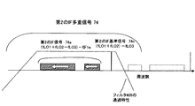
図4に、本発明の第2の実施形態のミリ波受信装置の詳細構成図示している。本実施形態における送信装置9までの構成は、第1の実施形態と同様であり省略し、受信装置400について説明する。また、図5Aは、ミリ波受信装置400の受信信号である無線多重信号72の周波数配置図を示す。図5Bと図5Cは、第2のIF多重信号74の周波数配置図を示す。図5Dは、この受信機の出力信号76(入力変調信号5eと同等)の周波数配置図を示す。
(Second Embodiment)
FIG. 4 shows a detailed configuration diagram of the millimeter wave receiver according to the second exemplary embodiment of the present invention. The configuration up to the transmission device 9 in this embodiment is the same as that in the first embodiment, and will be omitted. The
本実施形態では、受信出力信号76を復調する前に無線多重信号72を、一旦、局部発振器(発振周波数:fLO3)でダウンコンバートし、第2のIF多重信号74を生成する点で異なる。
The present embodiment is different in that the radio multiplexed
図4に示すように、無線受信装置400は、受信アンテナ101、第1のダウンコンバータ401および第2のダウンコンバータ402を備える。
As illustrated in FIG. 4, the
まず、第1のダウンコンバータ401について説明する。第1のダウンコンバータ401は、増幅器102とフィルタ103とミキサ403と局部発振器404とを備えている。
First, the
無線受信装置400において、受信アンテナ101により受信された無線多重信号72は、増幅器102で増幅された後、フィルタ103により帯域外不要波を除去し、ミキサ403に入力される。ミキサ403は、局部発振器404から生成される局部発振信号(fLO3)を用いてダウンコンバートすることによって、第2のIF多重信号74を出力する。
In
つまり、上記第1のダウンコンバータ401は、(第1の信号としての)無線信号72aと(第2の信号としての)無線基準信号72cとを含む無線多重信号を受信し、受信した無線多重信号を局部発振信号によりダウンコンバートして、(第1の中間周波数信号としての)第2のIF多重信号74を生成する。
That is, the
本実施形態では、第2のIF多重信号74が2〜5GHz程度になるようにした。尚、望ましい一実施例として、ミキサ403は偶高調波ミキサ等のN(N:2以上の自然数)次高調波ミキサ用いて、局部発振器404の局部発振周波数を1/Nとすることができる。例えば、2次の高調波ミキサとすることによって、局部発振器404の局部発振周波数を1/2とすることができる。
In the present embodiment, the second IF multiplexed
また、送受信無線信号72が、60GHz帯であるミリ波送受信装置であれば、局部発振器404の周波数は、25GHz〜30GHz帯でよく、直接60GHz帯で直接発振させる必要がないため、周波数安定度の高い送信機を、ワイアボンディング等の容易な実装で簡易に製作することができる。
Further, if the transmission /
第2のIF多重信号74を生成する過程は、図5Aと図5Bに示すような信号周波数配置となる。
The process of generating the second IF multiplexed
第2のIF基準信号74c: fLO1+fLO2−fLO3
第2のIF信号74a : fLO1+fLO2−fLO3−fIF1e
Second IF
Second IF signal 74a: fLO1 + fLO2-fLO3-fIF1e
第2のIF多重信号74は、第2のIF信号74aと第2のIF基準信号74cとで構成されている。また、ダウンコンバートによって周波数配列が反転しないように、fLO1+fLO2>fLO3となるようにすることが望ましい。受信装置400からの出力信号76の周波数特性を平坦にすることができる。
The second IF multiplexed
次に、図4に示すように、第2のダウンコンバータ402について説明する。
Next, the
上記第2のダウンコンバータ402は、第1の経路P1と、第2の経路P2と、上記第1の中間周波数信号を上記第1の経路P1と上記第2の経路P2とに分配する分配器407とを有する。
The second down-
上記第1の経路P1は、上記分配器407からの(第1の中間周波数信号としての)第2のIF多重信号74を上記ミキサ408に伝送する。
The
上記第2の経路P2は、(第1の中間周波数信号としての)第2のIF多重信号74から(第2の信号としての)第2のIF基準信号74cを抽出するフィルタ409と、このフィルタ409から抽出された(第2の信号としての)第2のIF基準信号74cを増幅する増幅器410とを有する。そして、この増幅された(第2の信号としての)第2のIF基準信号74cを上記ミキサ408に伝送する。
The second path P2 includes a
第2のダウンコンバータ402において、第1のダウンコンバータ401から出力される第2のIF多重信号74をフィルタ405、増幅器406で適宜不要波が除去され、増幅される。
In the
続いて、第2のIF多重信号74は、電力分配器407で2分配され、一方は、ミキサ408に入力される。他方は、第2のIF基準信号74cのみを通過させるバンドパスフィルタ409を介して、増幅器410によって増幅する。該バンドパスフィルタで抽出され増幅された第2のIF基準信号74cは、ミキサ408に入力される。ミキサ408において、第2のIF信号74aと増幅された第2のIF基準信号74cとを乗積、ダウンコンバートすることによって出力信号76を得る。
Subsequently, the second IF multiplexed
つまり、上記第2のダウンコンバータ402は、(第1の中間周波数信号としての)第2のIF多重信号74に含まれる(第1の信号としての)第2のIF信号74aと(第2の信号としての)第2のIF基準信号74cとを上記ミキサ408によりダウンコンバートして、(第2の中間周波数信号としての)出力信号76を生成する。
That is, the
具体的には、図5Cと図5D、および、下記の過程により、乗積・ダウンコンバートされる。 Specifically, multiplication and down-conversion are performed in accordance with FIGS. 5C and 5D and the following process.
(fLO1+fLO2−fLO3)−(fLO1+fLO2−fLO3−fIF1e)=fIF1e (FLO1 + fLO2-fLO3)-(fLO1 + fLO2-fLO3-fIF1e) = fIF1e
この復調された出力信号76は、図4に示すように、必要に応じてフィルタ172、増幅器195で濾波、増幅され、分波器(または分配器)190により分波(または分配)され、電子器機器38、例えばTV受像機中の衛星放送波用/地上波放送用チューナ39のそれぞれに接続される。
As shown in FIG. 4, the
次に、図6A〜図6Cに、ミキサ408の回路構成図を示す。本実施例のミキサは、図3A〜図3Cに示した第1の実施形態のミキサと比べ、入力される第2のIF多重信号74と第2のIF基準信号74cと電力合成する点で異なる。なお、図3A〜図3Cと同一の部分には、同一の参照番号を付して、詳細な説明を省略する。
Next, FIGS. 6A to 6C are circuit configuration diagrams of the
まず、ミキサ408に入力される第2のIF多重信号74と第2のIF基準信号74cを電力合成器601によって合成する。以降のミキサの構成は、第1の実施形態(図3A〜図3C)と周波数帯は異なるが、ミキサ103と同様の構成にしている。
First, the second IF multiplexed
一例として、図6Bに示したミキサ408を説明する。合成された第2のIF多重信号74と第2のIF基準信号74cをトランジスタ307で乗積すると、出力信号76が生成される。
As an example, the
以上の構成により、上記ミキサ408の動作バイアスを制御することができ、受信信号強度が大きくても小さくても、受信C/Nを確保することができるので、無線装置を広範囲の伝送距離で用いることができる。また、受信信号強度が大きくなりすぎても、トランジスタ307の動作電流が過剰になることを抑えるので、トランジスタ307が破壊されることを防ぐことができる。
With the above configuration, the operation bias of the
また、本実施例のように、第2のIF多重信号74と第2のIF基準信号74cとを合成してマイクロ波トランジスタのベースに注入するベース注入型ミキサであることが好ましい。ベース注入型の構成であれば増幅機能も有することにより、合成された2信号は増幅されるので、ミキサの入力ポートは少ない信号強度で周波数変換することができる。その結果、伝送距離を長くすることができる。
Further, as in this embodiment, it is preferable that the mixer be a base injection mixer that combines the second IF multiplexed
さらに、電力合成器601、電力分配器407は各出力ポート間でアイソレーション特性を持つウィルキンソン型電力分配・合成器あることが望ましい。ループ411によって回路に異常発振が生じ難くすることができる。
Further, it is desirable that the
本実施形態によれば、受信出力信号76を復調する前に無線多重信号72を、一端ダウンコンバートし、第2のIF多重信号74を生成している。従って、ミキサ408を含む第2のダウンコンバータ402は比較的低い周波数帯を扱うため、安価な部品で構成することができる。また、ミキサに入力される電力配分比(第2のIF信号74aの電力)/(第2のIF基準信号74cの電力)は、ミキサ408で受信感度の高い(受信C/Nがよい)ダウンコンバートを行うための最適条件が存在するが、第2のIF基準信号74cは増幅器410により増幅されるので、(図1、図2Bに示すように)あらかじめ送信器側での第1のIF多重信号71dの生成段階で、最適な電力配分比(第1のIF信号71aの電力)/(基準信号71cの電力)の設定値を高くすることができる。これにより周波数変換効率(受信感度)を高め、無線伝送距離をさらに拡大することを可能となる。
According to the present embodiment, before demodulating the
本実施形態では、上記経路P1を通過する第2のIF多重信号74には、第2のIF基準信号74cも含まれている。この信号を経路P2を通過する第2のIF基準信号74cを用いて、ミキサ408で周波数ダウンコンバートすることによっても、ダウンコンバートされた信号にはDC電流成分がいくらか発生する。このDC電流成分を用いて、ミキサ408のバイアス電流を制御することも可能である。具体的には、ダウンコンバートによって発生した電流は、受信感度に応じて変化する、つまり受信感度が強いときには大きなDC電流を発生し、受信感度が小さいときには小さなDC電流として発生する。このことを利用して、ミキサのバイアス制御することが可能となる。この結果、C/N劣化や高調波ひずみ特性劣化を小さくすることができる。
In the present embodiment, the second IF
本実施形態では、第2のIF多重信号74を増幅器406で増幅後、電力分配器407で2分配し、各信号をミキサ408に入力する構成にしているが、ミキサ408の動作バイアスを制御する構成であれば、適宜減衰器、フィルタ、増幅器が挿入されていても構わないし、分配せずにミキサ408に入力する構成にしても構わない。例えば、経路P1に第2のIF信号74aのみを通過させるバンドパスフィルタを挿入しても構わない。
In the present embodiment, the second IF multiplexed
(第3の実施形態)
図7に、本発明の第3の実施形態のミリ波受信装置の詳細構成図示している。ミリ波送信装置9の構成、および、受信機側ミリ波帯から第2のIF多重信号74を生成する部分までは同等である。第2のダウンコンバータで、第2のIF多重信号74を2分配し、分配された2信号を共に増幅器で増幅する点が第2の実施形態と異なる。
(Third embodiment)
FIG. 7 shows a detailed configuration diagram of the millimeter wave receiver according to the third exemplary embodiment of the present invention. The configuration of the millimeter wave transmission device 9 and the part that generates the second IF multiplexed
上記第2のダウンコンバータ402は、第1の経路P1と、第2の経路P2と、(第1の中間周波数信号としての)第2のIF多重信号74を上記第1の経路P1と上記第2の経路P2とに分配する分配器407とを有する。
The second down-
上記第1の経路P1は、(第1の中間周波数信号としての)第2のIF多重信号74を増幅する増幅器701を有する。そして、この増幅された(第1の中間周波数信号としての)第2のIF多重信号74を上記ミキサ408に伝送する。
The first path P1 has an
上記第2の経路P2は、(第1の中間周波数信号としての)第2のIF多重信号74から(第2の信号としての)第2のIF基準信号74cを抽出するフィルタ409と、このフィルタ409から抽出された(第2の信号としての)第2のIF基準信号74cを増幅する増幅器410とを有する。そして、この増幅された(第2の信号としての)第2のIF基準信号74cを上記ミキサ408に伝送する。
The second path P2 includes a
そして、上記第2のダウンコンバータ402では、第1のダウンコンバート後、第2のIF多重信号74はフィルタ405で適宜不要波が除去される。続いて、第2のIF多重信号74は、電力分配器407で2分配され、一方の信号は、増幅器701で増幅され、必要であれば減衰器702でレベル調整された後、ミキサ408に入力される。他方の信号は、第2のIF基準信号74cのみを通過させるバンドパスフィルタ409を介して、増幅器410によって増幅され、増幅された第2のIF基準信号74cをミキサ408に入力される。
In the
ミキサ408において、増幅およびレベル調整された第2のIF信号74aと増幅された第2のIF基準信号74cとを乗積し、ダウンコンバートすることによって、出力信号76を得る。ミキサ408は、第2の実施形態で説明したものと同じ構成である。
In the
本構成によれば、分配された2つの経路P1,P2ともに、増幅器410,701が接続されているので、増幅器410,701の高いアイソレーション作用によって、ループ411によって生じる帰還を抑えことができ、回路に異常発振が生じないようにすることができる。
According to this configuration, since the
(第4の実施形態)
図8に、本発明の第4の実施形態のミリ波受信装置の詳細構成図示している。ミリ波送信装置9の構成、および、受信機側ミリ波帯から第2のIF多重信号74を生成する部分までは同等である。第2のダウンコンバータで、第2のIF多重信号74から、この多重信号中に含まれる第2のIF基準信号74cによる周波数ダウンコンバートで、出力信号76を生成(入力変調波5eの再生)する部分が異なる。
(Fourth embodiment)
FIG. 8 shows a detailed configuration diagram of the millimeter wave receiver according to the fourth exemplary embodiment of the present invention. The configuration of the millimeter wave transmission device 9 and the part that generates the second IF multiplexed
上記第2のダウンコンバータ402は、第1の経路P1と、第2の経路P2と、第3の経路P3と、(第1の中間周波数信号としての)第2のIF多重信号74を上記第1の経路P1と上記第2の経路P2と上記第3の経路P3とに分配する分配器801aとを有する。
The
上記第1の経路P1は、(第1の中間周波数信号としての)第2のIF多重信号74から所定帯域の信号を抽出するフィルタ805を有する。そして、この所定帯域の信号を第1の上記ミキサ804aに伝送する。
The first path P1 includes a filter 805 that extracts a signal in a predetermined band from the second IF multiplexed signal 74 (as the first intermediate frequency signal). Then, the predetermined band signal is transmitted to the
上記第2の経路P2は、(第1の中間周波数信号としての)第2のIF多重信号74から所定帯域の信号を抽出するフィルタ806を有する。そして、この所定帯域の信号を第2の上記ミキサ804bに伝送する。
The second path P2 includes a
上記第3の経路P3は、(第1の中間周波数信号としての)第2のIF多重信号74から(第2の信号としての)第2のIF基準信号74cを抽出するフィルタ802と、このフィルタ802から抽出された(第2の信号としての)第2のIF基準信号74cを増幅する増幅器803a,803b,803cとを有する。そして、この増幅された(第2の信号としての)第2のIF基準信号74cを上記第1のミキサ804aおよび上記第2のミキサ804bに伝送する。
The third path P3 includes a
そして、上記第2のダウンコンバータ402では、第1のダウンコンバート後、フィルタ405により、第2のIF多重信号74を通過させたのち増幅器406で増幅したあと、電力分配器801aで3分配する。
In the
その後、上記第3の経路P3では、第2のIF基準信号74cを抽出するフィルタ802で第2のIF基準信号74cを抽出し、増幅分配後、夫々増幅器803a,803bで増幅され、上記第1のミキサ804aおよび上記第2のミキサ804bの局部発振信号となる。
Thereafter, in the third path P3, the second IF
一方、所望信号波は、フィルタ805およびフィルタ806で帯域分割し、第1の経路P1および第2の経路P2で、第2のIF多重信号74は、フィルタ805およびフィルタ806の特性に応じて、分波される。
On the other hand, the desired signal wave is band-divided by the filter 805 and the
このフィルタ805,806で分波された特性を、図9Aと図9Bに示す。なお、フィルタ802による第2のIF基準信号74cの抽出も同時に合わせて示している。
The characteristics demultiplexed by the
上記第1の経路P1では、フィルタ805は、第2のIF基準信号74cを含んで所望信号74aとして分波する。上記第2の経路P2では、フィルタ806は、所望信号波の一部だけの所望信号74bとして分波する。
In the first path P1, the filter 805 includes the second IF
具体例としては、図2で示した変調信号波に地上デジタル放送信号fIF1aと衛星放送信号fIF1bを用いた場合、フィルタ805では、該基準信号波74cと地上デジタル放送部74aが選択通過される。一方、フィルタ806では、衛星放送信号部74bが選択通過される。減衰器807a,807bで、レベル調整された後、夫々のミキサ804a,804bの入力信号となり、抽出された前記局部発振信号により周波数変換される。
As a specific example, when the terrestrial digital broadcast signal fIF1a and the satellite broadcast signal fIF1b are used for the modulated signal wave shown in FIG. 2, the filter 805 selectively passes the
第2の周波数変換された信号波は、図9Cに示すように、送信機への入力信号波である地上波信号fIF1aおよび衛星放送信号fIF1bが復調された構成となる。ミキサ804a,804bの構成は、第2の実施形態で説明した構成と同様にしているが、復調された地上波信号fIF1aおよび衛星放送信号fIF1bの受信C/N特性を夫々最適になるようにミキサ804a,804bの動作バイアスは別々に制御することが可能となる。そのため受信効率を高め、伝送距離を長くすることができる。
As shown in FIG. 9C, the second frequency-converted signal wave has a configuration in which the terrestrial signal fIF1a and the satellite broadcast signal fIF1b that are input signal waves to the transmitter are demodulated. The configurations of the
なお、減衰器807a,807bは、0.1dB〜3dB程度の弱い減衰器であるが、アイソレータや低利得の増幅器でも構わなく、該減衰器やアイソレータや低利得の増幅器により、上記第1の経路P1と上記第3の経路P3によってできるループL2、および、上記第2の経路P2と上記第3の経路P3によってできるループL3を負帰還ループに近づけることにより、抽出された該基準信号74cを局部発振源とするダウンコンバートをより安定におこなうことが可能となる。
Note that the
加えて、フィルタ805,806により帯域分割して、狭帯域でダウンコンバートを行い、周波数変換に伴う歪み、とりわけ、2次・3次高調波歪みの影響を低減することができる。加えて、3分配後に増幅器803a,803b,803cを配置し、ミキサ804a,804bにおいて、局発部を共用化し、かつ、2分配801b後に、増幅器803a,803bを配置しており、該増幅器のアイソレーション作用のため、夫々の第2のIF信号74a,74bが、ミキサ804a,804bの局発端子からの漏れるのを防ぐことができる。
In addition, the band can be divided by the
本実施形態でも、第2の実施形態と同様に、受信信号強度によってミキサの動作バイアスを制御するので、受信信号強度が大きくなりすぎても、ミキサの破壊を防ぐことができる。また、ミキサ804a、804bは別々に制御したが、共通に制御しても構わない。例えば、各ミキサのバイアス制御回路305や抵抗器320を1つに合わせて共通バイアス回路とし、各ミキサに同じ動作バイアスが供給されるようにしてもよい。
Also in this embodiment, as in the second embodiment, since the operation bias of the mixer is controlled by the received signal strength, it is possible to prevent the mixer from being destroyed even if the received signal strength becomes too large. The
本実施形態では経路P1には第2のIF基準信号74cが含まれているので、ダウンコンバートによって、ミキサ804aにはDC電流成分がいくらか発生し、その電流成分をバイアス制御に用いることができる。しかし、経路P2には第2のIF基準信号74cが含まれておらず、ダウンコンバートによって発生するDC電流成分が小さくなるのでこのDC電流成分をミキサ804bのバイアス制御に用いることが困難な場合には、バイアスを共通化しておくことにより、ミキサ804aで発生したDC電流成分でミキサ804bを制御することも可能となる。これによって、C/N劣化や歪特性劣化を小さくすることができる。
In the present embodiment, since the path IF includes the second IF
なお、上記実施形態では、入力変調波信号として地上放送波と衛星放送波で説明したが、二つの衛星放送波や、衛星放送波とCATV(Cable Television)信号等の組み合わせであっても構わないし、その他、例えば無線LAN等のIF段階またはRFでの変調波信号等を入力変調波信号としてもよい。 In the above-described embodiment, the terrestrial broadcast wave and the satellite broadcast wave have been described as the input modulation wave signal. However, a combination of two satellite broadcast waves or a satellite broadcast wave and a CATV (Cable Television) signal may be used. In addition, for example, a modulated wave signal in an IF stage or RF such as a wireless LAN may be used as the input modulated wave signal.
ここで、上記実施形態では、ミリ波帯の無線信号を送受信する無線通信システムについて説明したが、無線信号はミリ波帯に限るものではなく、ミリ波帯を含むマイクロ波の周波数帯域についてこの発明を適用することができる。 Here, in the above-described embodiment, the radio communication system that transmits and receives a millimeter-wave band radio signal has been described. However, the radio signal is not limited to the millimeter-wave band, and the present invention is applied to a microwave frequency band including the millimeter-wave band. Can be applied.
5e 入力変調信号(中間周波数信号)
72 無線多重信号
72a 無線信号(第1の信号)
72c 無線基準信号(第2の信号)
74 第2のIF多重信号(第1の中間周波数信号)
74a 第2のIF信号(第1の信号)
74c 第2のIF基準信号(第2の信号)
76 出力信号(第2の中間周波数信号)
100、400 無線受信装置
110 ダウンコンバータ
104、403、408、804a、804b ミキサ
304 検波回路
305 バイアス制御回路(制御部)
307 マイクロ波トランジスタ
320、602 抵抗器(制御部)
401 第1のダウンコンバータ
402 第2のダウンコンバータ
405、409、802、805,806 フィルタ
406、410、701、803a、803b、803c 増幅器
407、801a 電力分配器
601 電力合成器
900 無線受信装置
902、908、909 フィルタ
903、906、910 増幅器
905、911 ミキサ
P1 第1の経路
P2 第2の経路
P3 第3の経路
5e Input modulation signal (intermediate frequency signal)
72 radio multiplexed signal 72a radio signal (first signal)
72c Radio reference signal (second signal)
74 Second IF multiplexed signal (first intermediate frequency signal)
74a Second IF signal (first signal)
74c Second IF reference signal (second signal)
76 Output signal (second intermediate frequency signal)
100, 400
307
401 First down
Claims (9)
上記ミキサは、上記第1の信号または上記第2の信号の少なくともいずれか一方の信号強度に応じて、上記ミキサの動作バイアスを制御する制御部を有し、
上記ミキサは、上記無線多重信号をベースに受けて入力変調信号を出力するトランジスタを有し、
上記制御部は、上記無線多重信号の強度が大きいとき、上記トランジスタのベース電圧を低くする一方、上記無線多重信号の強度が小さいとき、上記トランジスタのベース電圧を高くするように制御することを特徴とする無線受信装置。 A radio multiplex signal including a first signal and a second signal is received, and the radio multiplex signal is down-converted by multiplying the first signal and the second signal by a mixer, and intermediate It has a down converter that generates a frequency signal,
The mixer has a control unit that controls an operation bias of the mixer according to the signal strength of at least one of the first signal and the second signal,
The mixer has a transistor that receives the radio multiplexed signal as a base and outputs an input modulation signal,
The control unit controls the base voltage of the transistor to be lowered when the strength of the wireless multiplex signal is large, while increasing the base voltage of the transistor when the strength of the wireless multiplex signal is small. A wireless receiver.
上記第1の中間周波数信号に含まれる上記第1の信号と上記第2の信号とをミキサにより乗積することで、上記第1の中間周波数信号をダウンコンバートして、第2の中間周波数信号を生成する第2のダウンコンバータと
を備え、
上記ミキサは、上記第1の信号または上記第2の信号の少なくともいずれか一方の信号強度に応じて、上記ミキサの動作バイアスを制御する制御部を有し、
上記ミキサは、上記無線多重信号をベースに受けて上記第2の中間周波数信号を出力するトランジスタを有し、
上記制御部は、上記無線多重信号の強度が大きいとき、上記トランジスタのベース電圧を低くする一方、上記無線多重信号の強度が小さいとき、上記トランジスタのベース電圧を高くするように制御することを特徴とする無線受信装置。 A first down converter that receives a radio multiplexed signal including a first signal and a second signal, down-converts the received radio multiplexed signal with a local oscillation signal, and generates a first intermediate frequency signal;
The first intermediate frequency signal is down-converted by multiplying the first signal and the second signal included in the first intermediate frequency signal by a mixer, thereby obtaining a second intermediate frequency signal. And a second down converter for generating
The mixer has a control unit that controls an operation bias of the mixer according to the signal strength of at least one of the first signal and the second signal,
The mixer has a transistor that receives the radio multiplexed signal as a base and outputs the second intermediate frequency signal,
The control unit controls the base voltage of the transistor to be lowered when the strength of the wireless multiplex signal is large, while increasing the base voltage of the transistor when the strength of the wireless multiplex signal is small. A wireless receiver.
上記第2のダウンコンバータは、
第1の経路と、
第2の経路と、
上記第1の中間周波数信号を上記第1の経路と上記第2の経路とに分配する分配器と
を有し、
上記第1の経路は、上記分配器からの上記第1の中間周波数信号を上記ミキサに伝送し、
上記第2の経路は、上記第1の中間周波数信号から上記第2の信号を抽出するフィルタと、このフィルタから抽出された上記第2の信号を増幅する増幅器とを有すると共に、この増幅された第2の信号を上記ミキサに伝送することを特徴とする無線受信装置。 The wireless receiver according to claim 2,
The second down converter is
A first path;
A second path;
A distributor for distributing the first intermediate frequency signal to the first path and the second path;
The first path transmits the first intermediate frequency signal from the distributor to the mixer;
The second path includes a filter that extracts the second signal from the first intermediate frequency signal, and an amplifier that amplifies the second signal extracted from the filter. A radio receiving apparatus that transmits a second signal to the mixer.
上記第2のダウンコンバータは、
第1の経路と、
第2の経路と、
上記第1の中間周波数信号を上記第1の経路と上記第2の経路とに分配する分配器と
を有し、
上記第1の経路は、上記第1の中間周波数信号を増幅する増幅器を有すると共に、この増幅された上記第1の中間周波数信号を上記ミキサに伝送し、
上記第2の経路は、上記第1の中間周波数信号から上記第2の信号を抽出するフィルタと、このフィルタから抽出された上記第2の信号を増幅する増幅器とを有すると共に、この増幅された第2の信号を上記ミキサに伝送することを特徴とする無線受信装置。 The wireless receiver according to claim 2,
The second down converter is
A first path;
A second path;
A distributor for distributing the first intermediate frequency signal to the first path and the second path;
The first path includes an amplifier that amplifies the first intermediate frequency signal, and transmits the amplified first intermediate frequency signal to the mixer.
The second path includes a filter that extracts the second signal from the first intermediate frequency signal, and an amplifier that amplifies the second signal extracted from the filter. A radio receiving apparatus that transmits a second signal to the mixer.
上記第2のダウンコンバータは、
第1の経路と、
第2の経路と、
第3の経路と、
上記第1の中間周波数信号を上記第1の経路と上記第2の経路と上記第3の経路とに分配する分配器と
を有し、
上記第1の経路は、上記第1の中間周波数信号から所定帯域の信号を抽出するフィルタを有すると共に、この所定帯域の信号を第1の上記ミキサに伝送し、
上記第2の経路は、上記第1の中間周波数信号から所定帯域の信号を抽出するフィルタを有すると共に、この所定帯域の信号を第2の上記ミキサに伝送し、
上記第3の経路は、上記第1の中間周波数信号から上記第2の信号を抽出するフィルタと、このフィルタから抽出された上記第2の信号を増幅する増幅器とを有すると共に、この増幅された第2の信号を上記第1のミキサおよび上記第2のミキサに伝送することを特徴とする無線受信装置。 The wireless receiver according to claim 2,
The second down converter is
A first path;
A second path;
A third path;
A distributor for distributing the first intermediate frequency signal to the first path, the second path, and the third path;
The first path includes a filter that extracts a signal in a predetermined band from the first intermediate frequency signal, and transmits the signal in the predetermined band to the first mixer.
The second path has a filter that extracts a signal of a predetermined band from the first intermediate frequency signal, and transmits the signal of the predetermined band to the second mixer,
The third path includes a filter that extracts the second signal from the first intermediate frequency signal, and an amplifier that amplifies the second signal extracted from the filter, and the amplified signal is amplified. A radio receiving apparatus that transmits a second signal to the first mixer and the second mixer.
上記ミキサは、マイクロ波トランジスタを有することを特徴とする無線受信装置。 The radio reception apparatus according to claim 1 or 2,
The mixer includes a microwave transistor.
上記ミキサは、上記第1の信号および上記第2の信号を上記マイクロ波トランジスタのベースに抽入するベース注入型ミキサであることを特徴とする無線受信装置。 The radio reception apparatus according to claim 6, wherein
The radio receiver according to claim 1, wherein the mixer is a base injection mixer that draws the first signal and the second signal into a base of the microwave transistor.
上記制御部は、抵抗器を有し、
この抵抗器は、上記ミキサから生じる電流を制御することによって、上記ミキサの動作バイアスを制御することを特徴とする無線受信装置。 The radio reception apparatus according to claim 1 or 2,
The control unit has a resistor,
The radio receiver according to claim 1, wherein the resistor controls an operation bias of the mixer by controlling a current generated from the mixer.
上記制御部は、抵抗器を有し、
この抵抗器は、10kΩ以上であり、上記マイクロ波トランジスタのベース端子に接続され、
この抵抗器は、上記ミキサから生じる電流を制御することによって、上記ミキサの動作バイアスを制御することを特徴とする無線受信装置。 The radio reception apparatus according to claim 6, wherein
The control unit has a resistor,
This resistor is 10 kΩ or more and is connected to the base terminal of the microwave transistor,
The radio receiver according to claim 1, wherein the resistor controls an operation bias of the mixer by controlling a current generated from the mixer.
Priority Applications (3)
| Application Number | Priority Date | Filing Date | Title |
|---|---|---|---|
| JP2005298866A JP4423251B2 (en) | 2005-10-13 | 2005-10-13 | Wireless receiver |
| US11/580,014 US20070087717A1 (en) | 2005-10-13 | 2006-10-13 | Radio receiver |
| US12/872,553 US8055223B2 (en) | 2005-10-13 | 2010-08-31 | Radio receiver |
Applications Claiming Priority (1)
| Application Number | Priority Date | Filing Date | Title |
|---|---|---|---|
| JP2005298866A JP4423251B2 (en) | 2005-10-13 | 2005-10-13 | Wireless receiver |
Publications (2)
| Publication Number | Publication Date |
|---|---|
| JP2007110400A JP2007110400A (en) | 2007-04-26 |
| JP4423251B2 true JP4423251B2 (en) | 2010-03-03 |
Family
ID=37948745
Family Applications (1)
| Application Number | Title | Priority Date | Filing Date |
|---|---|---|---|
| JP2005298866A Expired - Fee Related JP4423251B2 (en) | 2005-10-13 | 2005-10-13 | Wireless receiver |
Country Status (2)
| Country | Link |
|---|---|
| US (2) | US20070087717A1 (en) |
| JP (1) | JP4423251B2 (en) |
Families Citing this family (8)
| Publication number | Priority date | Publication date | Assignee | Title |
|---|---|---|---|---|
| KR100890634B1 (en) * | 2006-12-06 | 2009-03-27 | 한국전자통신연구원 | Rf repeater of time division duplexing and method thereof |
| JP2009088863A (en) * | 2007-09-28 | 2009-04-23 | Maspro Denkoh Corp | Millimeter wave reception system, and frequency converter |
| US8428528B2 (en) * | 2007-10-24 | 2013-04-23 | Biotronik Crm Patent Ag | Radio communications system designed for a low-power receiver |
| US8086200B2 (en) * | 2007-10-24 | 2011-12-27 | Biotronik Crm Patent Ag | Radio communications system designed for a low-power receiver |
| JP5004191B2 (en) * | 2008-09-16 | 2012-08-22 | シャープ株式会社 | Millimeter wave transmission / reception system |
| EP2388921B1 (en) * | 2010-05-21 | 2013-07-17 | Nxp B.V. | Integrated circuits with frequency generating circuits |
| US9184771B2 (en) * | 2011-10-12 | 2015-11-10 | Optis Cellular Technology, Llc | Digital down conversion and demodulation |
| US9362964B2 (en) * | 2012-05-07 | 2016-06-07 | Zte (Usa) Inc. | Receiver architecture for dual receiver signal level and interference detection in microwave digital radio applications |
Family Cites Families (13)
| Publication number | Priority date | Publication date | Assignee | Title |
|---|---|---|---|---|
| US4160213A (en) * | 1977-09-29 | 1979-07-03 | Rca Corporation | Mixer injection voltage compensation circuit |
| US4947062A (en) * | 1988-05-19 | 1990-08-07 | Adams Russell Electronics Co., Inc. | Double balanced mixing |
| US5548222A (en) * | 1994-09-29 | 1996-08-20 | Forte Networks | Method and apparatus for measuring attenuation and crosstalk in data and communication channels |
| US5837589A (en) * | 1996-12-27 | 1998-11-17 | Raytheon Company | Method for making heterojunction bipolar mixer circuitry |
| JP2001127658A (en) | 1999-10-22 | 2001-05-11 | Denso Corp | Receiver and portable telephone set |
| JP2001211092A (en) | 2000-01-25 | 2001-08-03 | Toyo Commun Equip Co Ltd | Radio transmission system |
| DE10009143B4 (en) * | 2000-02-26 | 2012-04-26 | Eberhard-Karls-Universität Tübingen Universitätsklinikum | Detection of Human Papillomaviruses |
| JP3992222B2 (en) | 2002-02-27 | 2007-10-17 | 独立行政法人情報通信研究機構 | Transmitter, transmission method, receiver, reception method, radio communication apparatus, and radio communication method |
| CA2415917A1 (en) * | 2003-01-08 | 2004-07-08 | Sirific Wireless Corporation | Regenerative divider used for up-conversion and down conversion |
| US6693578B1 (en) * | 2003-03-18 | 2004-02-17 | Beltronics Usa, Inc. | Mixer optimization for active radar warning receiver |
| JP2004343242A (en) | 2003-05-13 | 2004-12-02 | Alps Electric Co Ltd | Reception circuit |
| JP4138639B2 (en) | 2003-06-30 | 2008-08-27 | シャープ株式会社 | Microwave wireless communication system and electronic device |
| US7202916B2 (en) * | 2003-12-15 | 2007-04-10 | Realtek Semiconductor Corp. | Television tuner and method of processing a received RF signal |
-
2005
- 2005-10-13 JP JP2005298866A patent/JP4423251B2/en not_active Expired - Fee Related
-
2006
- 2006-10-13 US US11/580,014 patent/US20070087717A1/en not_active Abandoned
-
2010
- 2010-08-31 US US12/872,553 patent/US8055223B2/en not_active Expired - Fee Related
Also Published As
| Publication number | Publication date |
|---|---|
| JP2007110400A (en) | 2007-04-26 |
| US20070087717A1 (en) | 2007-04-19 |
| US20100330945A1 (en) | 2010-12-30 |
| US8055223B2 (en) | 2011-11-08 |
Similar Documents
| Publication | Publication Date | Title |
|---|---|---|
| JP6009251B2 (en) | Millimeter wave transmission module and millimeter wave transmission device | |
| US8055223B2 (en) | Radio receiver | |
| EP2630693A1 (en) | Systems and methods for improved power yield and linearization in radio frequency transmitters | |
| WO2012097085A1 (en) | Systems and methods for a radio frequency transmitter with improved linearity and power out utilizing pre-distortion and a gan (gallium nitride) power amplifier device | |
| US10944438B2 (en) | Communication unit | |
| JP3996902B2 (en) | Microwave band radio receiver and microwave band radio communication system | |
| JP4138758B2 (en) | Wireless receiver, wireless communication system, and electronic device | |
| JP4699336B2 (en) | Wireless receiver and electronic device | |
| US7035610B2 (en) | AGC circuit of receiver using several local oscillation frequencies | |
| JP2007006451A (en) | Terrestrial dmb receiver | |
| JP6952040B2 (en) | Receiver and receiving system | |
| JP4250125B2 (en) | Wireless transmission device | |
| JP4138639B2 (en) | Microwave wireless communication system and electronic device | |
| JP4486608B2 (en) | Microwave band radio transmitter, microwave band radio receiver and microwave band radio transceiver system | |
| JP4385661B2 (en) | TV multidirectional receiver | |
| JP2003283352A (en) | High frequency receiver | |
| JP4769646B2 (en) | Broadband photoelectric conversion circuit | |
| JP5215082B2 (en) | Millimeter wave transmitter and millimeter wave transceiver system | |
| KR20020030379A (en) | Double conversion type tuner for using trap circuit | |
| JP2006074576A (en) | If signal processing circuit | |
| JP2004048123A (en) | Tuner for receiving satellite broadcast | |
| KR20110065033A (en) | RF signal processing circuit |
Legal Events
| Date | Code | Title | Description |
|---|---|---|---|
| A977 | Report on retrieval |
Free format text: JAPANESE INTERMEDIATE CODE: A971007 Effective date: 20081119 |
|
| A131 | Notification of reasons for refusal |
Free format text: JAPANESE INTERMEDIATE CODE: A131 Effective date: 20081202 |
|
| A521 | Written amendment |
Free format text: JAPANESE INTERMEDIATE CODE: A523 Effective date: 20090123 |
|
| A131 | Notification of reasons for refusal |
Free format text: JAPANESE INTERMEDIATE CODE: A131 Effective date: 20090224 |
|
| A521 | Written amendment |
Free format text: JAPANESE INTERMEDIATE CODE: A523 Effective date: 20090416 |
|
| TRDD | Decision of grant or rejection written | ||
| A01 | Written decision to grant a patent or to grant a registration (utility model) |
Free format text: JAPANESE INTERMEDIATE CODE: A01 Effective date: 20091201 |
|
| A01 | Written decision to grant a patent or to grant a registration (utility model) |
Free format text: JAPANESE INTERMEDIATE CODE: A01 |
|
| A61 | First payment of annual fees (during grant procedure) |
Free format text: JAPANESE INTERMEDIATE CODE: A61 Effective date: 20091207 |
|
| FPAY | Renewal fee payment (event date is renewal date of database) |
Free format text: PAYMENT UNTIL: 20121211 Year of fee payment: 3 |
|
| R150 | Certificate of patent or registration of utility model |
Free format text: JAPANESE INTERMEDIATE CODE: R150 |
|
| FPAY | Renewal fee payment (event date is renewal date of database) |
Free format text: PAYMENT UNTIL: 20121211 Year of fee payment: 3 |
|
| LAPS | Cancellation because of no payment of annual fees |