[go: up one dir, main page]

JP4416028B2 - Ultrasonic beauty equipment - Google Patents

Ultrasonic beauty equipment Download PDF

Info

Publication number
JP4416028B2
JP4416028B2 JP2007255220A JP2007255220A JP4416028B2 JP 4416028 B2 JP4416028 B2 JP 4416028B2 JP 2007255220 A JP2007255220 A JP 2007255220A JP 2007255220 A JP2007255220 A JP 2007255220A JP 4416028 B2 JP4416028 B2 JP 4416028B2
Authority
JP
Japan
Prior art keywords
head
probe
base
ultrasonic
main body
Prior art date
Legal status (The legal status is an assumption and is not a legal conclusion. Google has not performed a legal analysis and makes no representation as to the accuracy of the status listed.)
Active
Application number
JP2007255220A
Other languages
Japanese (ja)
Other versions
JP2009082377A (en
Inventor
建志 松坂
真一 谷口
篤子 岸本
至 齋田
拓史 荘村
Current Assignee (The listed assignees may be inaccurate. Google has not performed a legal analysis and makes no representation or warranty as to the accuracy of the list.)
Panasonic Corp
Panasonic Electric Works Co Ltd
Original Assignee
Panasonic Corp
Matsushita Electric Works Ltd
Priority date (The priority date is an assumption and is not a legal conclusion. Google has not performed a legal analysis and makes no representation as to the accuracy of the date listed.)
Filing date
Publication date
Application filed by Panasonic Corp, Matsushita Electric Works Ltd filed Critical Panasonic Corp
Priority to JP2007255220A priority Critical patent/JP4416028B2/en
Priority to EP08016708A priority patent/EP2042148A1/en
Priority to CN2008101687097A priority patent/CN101396592B/en
Priority to RU2008138461/14A priority patent/RU2392918C1/en
Publication of JP2009082377A publication Critical patent/JP2009082377A/en
Priority to HK09105767.1A priority patent/HK1126702A1/en
Application granted granted Critical
Publication of JP4416028B2 publication Critical patent/JP4416028B2/en
Active legal-status Critical Current
Anticipated expiration legal-status Critical

Links

Images

Classifications

    • AHUMAN NECESSITIES
    • A61MEDICAL OR VETERINARY SCIENCE; HYGIENE
    • A61HPHYSICAL THERAPY APPARATUS, e.g. DEVICES FOR LOCATING OR STIMULATING REFLEX POINTS IN THE BODY; ARTIFICIAL RESPIRATION; MASSAGE; BATHING DEVICES FOR SPECIAL THERAPEUTIC OR HYGIENIC PURPOSES OR SPECIFIC PARTS OF THE BODY
    • A61H7/00Devices for suction-kneading massage; Devices for massaging the skin by rubbing or brushing not otherwise provided for
    • A61H7/002Devices for suction-kneading massage; Devices for massaging the skin by rubbing or brushing not otherwise provided for by rubbing or brushing
    • A61H7/004Devices for suction-kneading massage; Devices for massaging the skin by rubbing or brushing not otherwise provided for by rubbing or brushing power-driven, e.g. electrical
    • A61H7/005Devices for suction-kneading massage; Devices for massaging the skin by rubbing or brushing not otherwise provided for by rubbing or brushing power-driven, e.g. electrical hand-held
    • AHUMAN NECESSITIES
    • A61MEDICAL OR VETERINARY SCIENCE; HYGIENE
    • A61HPHYSICAL THERAPY APPARATUS, e.g. DEVICES FOR LOCATING OR STIMULATING REFLEX POINTS IN THE BODY; ARTIFICIAL RESPIRATION; MASSAGE; BATHING DEVICES FOR SPECIAL THERAPEUTIC OR HYGIENIC PURPOSES OR SPECIFIC PARTS OF THE BODY
    • A61H23/00Percussion or vibration massage, e.g. using supersonic vibration; Suction-vibration massage; Massage with moving diaphragms
    • A61H23/02Percussion or vibration massage, e.g. using supersonic vibration; Suction-vibration massage; Massage with moving diaphragms with electric or magnetic drive
    • A61H23/0245Percussion or vibration massage, e.g. using supersonic vibration; Suction-vibration massage; Massage with moving diaphragms with electric or magnetic drive with ultrasonic transducers, e.g. piezoelectric
    • AHUMAN NECESSITIES
    • A61MEDICAL OR VETERINARY SCIENCE; HYGIENE
    • A61HPHYSICAL THERAPY APPARATUS, e.g. DEVICES FOR LOCATING OR STIMULATING REFLEX POINTS IN THE BODY; ARTIFICIAL RESPIRATION; MASSAGE; BATHING DEVICES FOR SPECIAL THERAPEUTIC OR HYGIENIC PURPOSES OR SPECIFIC PARTS OF THE BODY
    • A61H23/00Percussion or vibration massage, e.g. using supersonic vibration; Suction-vibration massage; Massage with moving diaphragms
    • A61H23/02Percussion or vibration massage, e.g. using supersonic vibration; Suction-vibration massage; Massage with moving diaphragms with electric or magnetic drive
    • A61H23/0254Percussion or vibration massage, e.g. using supersonic vibration; Suction-vibration massage; Massage with moving diaphragms with electric or magnetic drive with rotary motor
    • A61H23/0263Percussion or vibration massage, e.g. using supersonic vibration; Suction-vibration massage; Massage with moving diaphragms with electric or magnetic drive with rotary motor using rotating unbalanced masses
    • AHUMAN NECESSITIES
    • A61MEDICAL OR VETERINARY SCIENCE; HYGIENE
    • A61HPHYSICAL THERAPY APPARATUS, e.g. DEVICES FOR LOCATING OR STIMULATING REFLEX POINTS IN THE BODY; ARTIFICIAL RESPIRATION; MASSAGE; BATHING DEVICES FOR SPECIAL THERAPEUTIC OR HYGIENIC PURPOSES OR SPECIFIC PARTS OF THE BODY
    • A61H2201/00Characteristics of apparatus not provided for in the preceding codes
    • A61H2201/01Constructive details
    • A61H2201/0119Support for the device
    • A61H2201/0153Support for the device hand-held
    • AHUMAN NECESSITIES
    • A61MEDICAL OR VETERINARY SCIENCE; HYGIENE
    • A61HPHYSICAL THERAPY APPARATUS, e.g. DEVICES FOR LOCATING OR STIMULATING REFLEX POINTS IN THE BODY; ARTIFICIAL RESPIRATION; MASSAGE; BATHING DEVICES FOR SPECIAL THERAPEUTIC OR HYGIENIC PURPOSES OR SPECIFIC PARTS OF THE BODY
    • A61H2201/00Characteristics of apparatus not provided for in the preceding codes
    • A61H2201/16Physical interface with patient
    • A61H2201/1602Physical interface with patient kind of interface, e.g. head rest, knee support or lumbar support
    • A61H2201/1604Head
    • AHUMAN NECESSITIES
    • A61MEDICAL OR VETERINARY SCIENCE; HYGIENE
    • A61HPHYSICAL THERAPY APPARATUS, e.g. DEVICES FOR LOCATING OR STIMULATING REFLEX POINTS IN THE BODY; ARTIFICIAL RESPIRATION; MASSAGE; BATHING DEVICES FOR SPECIAL THERAPEUTIC OR HYGIENIC PURPOSES OR SPECIFIC PARTS OF THE BODY
    • A61H2205/00Devices for specific parts of the body
    • A61H2205/02Head
    • A61H2205/022Face

Landscapes

  • Health & Medical Sciences (AREA)
  • Epidemiology (AREA)
  • Pain & Pain Management (AREA)
  • Physical Education & Sports Medicine (AREA)
  • Rehabilitation Therapy (AREA)
  • Life Sciences & Earth Sciences (AREA)
  • Animal Behavior & Ethology (AREA)
  • General Health & Medical Sciences (AREA)
  • Public Health (AREA)
  • Veterinary Medicine (AREA)
  • Dermatology (AREA)
  • Percussion Or Vibration Massage (AREA)

Description

本発明は、超音波振動子から付与される超音波振動を、プローブヘッドを介して肌表面に伝達させる超音波美容器具に関する。   The present invention relates to an ultrasonic beauty instrument that transmits ultrasonic vibration applied from an ultrasonic transducer to a skin surface via a probe head.

従来の超音波美容器具の一例として、金属製のプローブヘッドとこのプローブヘッドに超音波振動を付与する超音波振動子を備えるヘッド部を二つ設けたものが知られている(例えば、下記特許文献1参照)。   As an example of a conventional ultrasonic beauty instrument, a metal probe head and two head portions each having an ultrasonic transducer for applying ultrasonic vibration to the probe head are known (for example, the following patents) Reference 1).

この二つのヘッド部のうち一方は、顔部に対して美肌効果を得るためのものであり、他方は、身体に対する痩身効果を得るためのものであり、この際、二つの超音波振動子に対し、スイッチの切り替え操作によって、異なる超音波周波数を与えるよう選択的に動作させている。   One of the two head parts is for obtaining a skin-beautifying effect on the face part, and the other is for obtaining a slimming effect on the body. On the other hand, it is selectively operated to give different ultrasonic frequencies by switching operation of the switch.

特開2001−252323号公報JP 2001-252323 A

しかしながら、上記した従来の超音波美容器具は、二つのヘッド部によって顔部に対する美肌効果と、身体に対する痩身効果を得るようにしているものの、顔部の細部に対して美肌効果を得ることについては考慮していない。   However, although the above-mentioned conventional ultrasonic beauty instruments are designed to obtain a skin beautifying effect on the face and a slimming effect on the body with two head parts, it is possible to obtain a skin beautifying effect on the details of the face. Not considered.

そこで本発明は、複数のヘッド部によって、顔部の主要部分に対する美肌効果に加え、顔部の細部に対する美肌効果も得られるようにすることを目的としている。   In view of the above, an object of the present invention is to obtain a skin beautifying effect on the details of the face portion in addition to a skin beautifying effect on the main portion of the face portion by using a plurality of head portions.

請求項1の発明は、超音波振動子から付与される超音波振動を、プローブヘッドを介して肌表面に伝達させる超音波美容器具において、本体部に対し、導電材料からなる前記プローブヘッドを備えたヘッド部を複数設け、この複数のヘッド部の、前記肌表面に接触させるプローブヘッドの接触面の大きさを互いに異ならせ、前記各プローブヘッドに対応して設けたそれぞれの超音波振動子に対し、同一の制御回路から同一の超音波周波数を供給する構成とし、前記複数のヘッド部は、それぞれの前記超音波振動子が対応する前記各プローブヘッドの背面に取り付けられるとともに、前記超音波振動子の前記プローブヘッドと反対側に位置する基台と、この基台の外周側に位置して該基台とで前記プローブヘッドの外周縁を挟持固定するプローブカバーとを備え、かつ前記複数のヘッド部は、前記制御回路に一端が接続される一対のリード線の各他端を、前記基台に取り付けた一対の接続金具の一端にそれぞれ接続し、前記プローブカバーと前記基台とで前記プローブヘッドの外周縁を挟持固定した状態で、前記各接続金具の他端を前記超音波振動子の背面と前記プローブヘッドの背面とにそれぞれ押し付けて接続することを特徴とする。 According to a first aspect of the present invention, there is provided an ultrasonic beauty instrument for transmitting ultrasonic vibration applied from an ultrasonic transducer to the skin surface via the probe head, the probe head made of a conductive material provided to the main body. A plurality of head portions are provided, and the sizes of the contact surfaces of the probe heads that are in contact with the skin surface of the plurality of head portions are different from each other. On the other hand, the same ultrasonic frequency is supplied from the same control circuit , and the plurality of head portions are attached to the back surfaces of the probe heads to which the respective ultrasonic transducers correspond, and the ultrasonic vibrations. A base that is located on the opposite side of the probe head from the probe, and a probe that sandwiches and fixes the outer periphery of the probe head between the base and the base that is located on the outer peripheral side of the base And a plurality of head portions, each of the other ends of the pair of lead wires, one end of which is connected to the control circuit, is connected to one end of a pair of connection fittings attached to the base, With the probe cover and the base holding and fixing the outer periphery of the probe head, the other end of each connection fitting is pressed against the back surface of the ultrasonic transducer and the back surface of the probe head, respectively, and connected. It is characterized by.

請求項2の発明は、請求項1に記載の超音波美容器具であって、前記本体部に対して前記ヘッド部を二つ設け、この二つのヘッド部と前記本体部とで正面視でY字形状となるよう形成したことを特徴とする。   The invention according to claim 2 is the ultrasonic beauty instrument according to claim 1, wherein two head parts are provided for the main body part, and the two head parts and the main body part are Y in front view. It is formed to have a letter shape.

請求項3の発明は、請求項2に記載の超音波美容器具であって、前記二つのヘッド部のうち一方は、該ヘッド部が取り付けられるベース部に対して直角方向に移動可能かつ、この直角方向の中心軸に対して揺動可能であることを特徴とする。   The invention of claim 3 is the ultrasonic beauty instrument according to claim 2, wherein one of the two head portions is movable in a direction perpendicular to a base portion to which the head portion is attached, and It is swingable with respect to a central axis in a perpendicular direction.

請求項4の発明は、請求項3に記載の超音波美容器具であって、前記二つのヘッド部のうち一方は、前記ベース部に対し弾性手段を介して前記直角方向に移動可能に支持されるとともに、前記ベース部中心の貫通孔に基端部を移動可能に挿入して前記ベース部に弾性体を介して取り付けたことを特徴とする。   The invention of claim 4 is the ultrasonic beauty instrument according to claim 3, wherein one of the two head parts is supported so as to be movable in the perpendicular direction to the base part via elastic means. And a base end portion is movably inserted into the through hole at the center of the base portion and attached to the base portion via an elastic body.

請求項5の発明は、請求項1ないし4のいずれか1項に記載の超音波美容器具であって、前記複数のヘッド部は、防水構造を備えていることを特徴とする。   A fifth aspect of the invention is the ultrasonic beauty instrument according to any one of the first to fourth aspects, wherein the plurality of head portions are provided with a waterproof structure.

請求項6の発明は、請求項5に記載の超音波美容器具であって、前記二つのヘッド部のうち一方は、前記プローブヘッドと該プローブヘッドの外周縁を固定するプローブカバーの先端側との間にシール部材を設けて防水構造としたことを特徴とする。   Invention of Claim 6 is the ultrasonic beauty instrument of Claim 5, Comprising: One of these two head parts is the front end side of the probe cover which fixes the said probe head and the outer periphery of this probe head, A sealing member is provided between the two to form a waterproof structure.

請求項7の発明は、請求項6に記載の超音波美容器具であって、前記プローブカバーの基端側にヘッドベースを設け、このヘッドベースと前記プローブカバーとの間にシール部材を設けて防水構造としたことを特徴とする。   The invention according to claim 7 is the ultrasonic beauty instrument according to claim 6, wherein a head base is provided on the proximal end side of the probe cover, and a seal member is provided between the head base and the probe cover. It is characterized by a waterproof structure.

請求項8の発明は、請求項5ないし7のいずれか1項に記載の超音波美容器具であって、前記二つのヘッド部のうち一方は、該ヘッド部が取り付けられるベース部に対して直角方向に移動可能かつ、この直角方向の中心軸に対して揺動可能であり、前記ベース部と、該ベース部を取り付ける前記本体部側との間にシール部材を設けて防水構造としたことを特徴とする。   The invention of claim 8 is the ultrasonic beauty instrument according to any one of claims 5 to 7, wherein one of the two head parts is perpendicular to a base part to which the head part is attached. It is movable in the direction and swingable with respect to the central axis in the perpendicular direction, and a waterproof structure is provided by providing a seal member between the base portion and the main body portion side to which the base portion is attached. Features.

請求項9の発明は、請求項5ないし8のいずれか1項に記載の超音波美容器具であって、前記二つのヘッド部のうち他方は、前記プローブヘッドと該プローブヘッドの外周縁を固定するプローブカバーの先端側との間及び、前記プローブカバーの基端側と、この基端側を取り付ける前記本体部側との間にシール部材を設けて防水構造としたことを特徴とする。   The invention of claim 9 is the ultrasonic beauty instrument according to any one of claims 5 to 8, wherein the other of the two head portions fixes the probe head and the outer peripheral edge of the probe head. A seal member is provided between the distal end side of the probe cover and between the proximal end side of the probe cover and the main body portion side to which the proximal end side is attached to form a waterproof structure.

請求項10の発明は、請求項1ないし9のいずれか1項に記載の超音波美容器具であって、前記本体部の前記ヘッド部と反対側の端部に端部カバーを設け、この端部カバーと前記本体部のハウジングと間にシール部材を設けて防水構造とするとともに、前記本体部に設けたスイッチ部にシール部材を設けて防水構造としたことを特徴とする。   The invention of claim 10 is the ultrasonic beauty instrument according to any one of claims 1 to 9, wherein an end cover is provided at an end portion of the main body portion opposite to the head portion, and this end portion is provided. A seal member is provided between the part cover and the housing of the main body part to provide a waterproof structure, and a switch member provided on the main body part is provided with a seal member to provide a waterproof structure.

請求項11の発明は、請求項1ないし10のいずれか1項に記載の超音波美容器具であって、前記同一の制御回路は、前記本体部に設けたスイッチ部の操作によって前記複数のヘッド部を選択的に動作させることを特徴とする。   The invention of claim 11 is the ultrasonic beauty instrument according to any one of claims 1 to 10, wherein the same control circuit is configured to operate the plurality of heads by operating a switch unit provided in the main body. It is characterized by selectively operating the unit.

請求項1の発明によれば、肌表面に接触させるプローブヘッドの接触面が大きい方のヘッド部を顔部の頬などの主要部分に使用する一方、プローブヘッドの接触面が小さい方のヘッド部を鼻部などの細部に使用することで、顔部の主要部分に対する美肌効果に加え、顔部の細部に対する美肌効果も得ることができる。この際、同一の制御回路から同一の超音波周波数を供給する構成とすることで、器具全体の小型化を達成することができる。   According to the first aspect of the present invention, the head portion having the larger contact surface of the probe head to be brought into contact with the skin surface is used as the main portion such as the cheek of the face portion, while the head portion having the smaller contact surface of the probe head. In addition to the skin beautifying effect on the main part of the face, the skin beautifying effect on the details of the face can be obtained. At this time, the entire apparatus can be reduced in size by supplying the same ultrasonic frequency from the same control circuit.

請求項2の発明によれば、使用者が本体部を自然に把持した状態で、ヘッド部の先端に設けたプローブヘッドの接触面を肌表面に接触させやすくなり、T字形状とした場合に比較して使い勝手が向上する。   According to the invention of claim 2, when the user naturally grips the main body part, the contact surface of the probe head provided at the tip of the head part can be easily brought into contact with the skin surface, and the shape is T-shaped. Usability is improved in comparison.

請求項3または4の発明によれば、肌の表面形状に合わせてプローブヘッドの接触面が容易に追従し、該接触面を肌の表面に接触させやすくなる。   According to invention of Claim 3 or 4, the contact surface of a probe head follows easily according to the surface shape of skin, and it becomes easy to make this contact surface contact the surface of skin.

請求項5ないし10の発明によれば、器具内部への異物、例えば水やジェルなどの液体や固体の浸入を防止することができ、内部に設けた制御回路部品などを保護することができる。   According to the fifth to tenth aspects of the present invention, it is possible to prevent foreign substances, for example, liquids such as water and gel and solids from entering the apparatus, and to protect control circuit components provided inside.

請求項11の発明によれば、二つのヘッド部をスイッチ操作によって独立して動作させることができ、本体部を大きく持ち変えることなく、顔部の主要部分に対する美肌効果に加え、顔部の細部に対する美肌効果を得ることができる。   According to the eleventh aspect of the invention, the two head portions can be independently operated by a switch operation, and the details of the face portion can be obtained in addition to the skin beautifying effect on the main portion of the face portion without greatly changing the main body portion. The skin-beautifying effect can be obtained.

以下、本発明の実施の形態を図面に基づき説明する。   Hereinafter, embodiments of the present invention will be described with reference to the drawings.

図1は、本発明の一実施形態を示す超音波美容器具の正面図である。   FIG. 1 is a front view of an ultrasonic beauty instrument showing an embodiment of the present invention.

この超音波美容器具は、使用者が手で掴む部分となる本体部1と、本体部1の先端(図1中で上端)に位置するヘッド基台部3と、ヘッド基台部3から左右に分岐するようにして突出する第1ヘッド5部及び第2ヘッド部7とを、それぞれ備えている。これら第1,第2各ヘッド部5,7は複数のヘッド部を構成しており、図1の正面視で示すように、本体部1の上端のヘッド基台部3から、やや斜め上方に指向しており、これにより本超音波美容器具は全体としてY字形状となるよう形成していることになる。   The ultrasonic beauty instrument includes a main body 1 that is a part that a user grasps with a hand, a head base 3 that is located at the tip of the main body 1 (upper end in FIG. 1), and left and right from the head base 3. The first head portion 5 and the second head portion 7 that protrude so as to branch to each other are provided. Each of the first and second head portions 5 and 7 constitutes a plurality of head portions. As shown in a front view of FIG. 1, the head base portion 3 at the upper end of the main body portion 1 is slightly inclined upward. Thus, the ultrasonic beauty instrument is formed in a Y shape as a whole.

第1ヘッド部5は、その先端に設けてある導電性材料からなる第1プローブヘッド9(図6参照)と、その周囲を覆うようにして設けてあるアタッチメント11とにより、人の鼻部に直接接触させて超音波振動を与え、美肌効果を得る。一方、第2ヘッド部7は、その先端に設けてある導電性材料からなる第2プローブヘッド13により、人の顔部における頬などの主要となる部位に接触させて超音波振動を与え、美肌効果を得る。   The first head portion 5 is attached to a human nose by a first probe head 9 (see FIG. 6) made of a conductive material provided at the tip thereof and an attachment 11 provided so as to cover the periphery thereof. Applying ultrasonic vibration by direct contact to obtain a beautiful skin effect. On the other hand, the second head portion 7 is brought into contact with a main part such as a cheek in a human face by the second probe head 13 made of a conductive material provided at the tip thereof, thereby applying ultrasonic vibrations to beautify the skin. Get the effect.

図2は、図1の背面図であり、これら第1,第2各ヘッド部5,7を選択的に切り替えて動作させるためのスイッチ部を構成するスイッチ15を、本体部1の上部に設けている。スイッチ15の周囲には、スイッチパネル17を設けている。   FIG. 2 is a rear view of FIG. 1, and a switch 15 constituting a switch unit for selectively switching the first and second head units 5 and 7 to operate is provided on the upper portion of the main body unit 1. ing. A switch panel 17 is provided around the switch 15.

図1に示すように、本体部1には、上記したスイッチ15による超音波美容器具の充電状態を示すLED19及び、その上部に第1,第2各ヘッド部5,7の動作状態を示すLED21,23,25をそれぞれ設けている。   As shown in FIG. 1, the main body 1 includes an LED 19 that indicates the state of charge of the ultrasonic beauty instrument by the switch 15 described above, and an LED 21 that indicates the operating state of the first and second head portions 5 and 7 on the upper portion thereof. , 23 and 25 are provided.

上記した第1,第2各ヘッド部5,7には、図3に示すように、不使用時に装着するキャップ27,29を備えている。   As shown in FIG. 3, the first and second head portions 5 and 7 are provided with caps 27 and 29 to be mounted when not in use.

図4は、超音波美容器具の分解斜視図で、図5は図2のA−A断面図である。本体部1のハウジング31内には、回路基台33を収容してあり、回路基台33の、前記したスイッチ15を設けた側と反対側には、本体回路基板35をリブ33aによって固定している。回路基台33は、その上部に設けてあるねじ孔33bに、ねじ37を挿入して後述するヘッド基台61に固定している。なお、図4中で符号36は、後述する第1超音波振動子75と第2超音波振動子107を、同一の超音波周波数で超音波振動させるための同一の制御回路を備える振動子制御回路基板であり、本体回路基板35に配線接続される。   4 is an exploded perspective view of the ultrasonic beauty instrument, and FIG. 5 is a cross-sectional view taken along line AA of FIG. A circuit base 33 is accommodated in the housing 31 of the main body 1, and the main body circuit board 35 is fixed by a rib 33 a on the opposite side of the circuit base 33 from the side where the switch 15 is provided. ing. The circuit base 33 is fixed to a head base 61 to be described later by inserting a screw 37 into a screw hole 33b provided in the upper part of the circuit base 33. In FIG. 4, reference numeral 36 denotes a vibrator control that includes the same control circuit for causing a first ultrasonic vibrator 75 and a second ultrasonic vibrator 107 to be described later to ultrasonically vibrate at the same ultrasonic frequency. It is a circuit board and is connected to the main circuit board 35 by wiring.

回路基台33の、スイッチ15を設けた側の下部には、充電池組立品39を収容しており、該充電池組立品39の図4中で下部には電池陽極金具41を、上部には電池陰極金具43を、それぞれ配置している。   A rechargeable battery assembly 39 is accommodated in the lower part of the circuit base 33 on the side where the switch 15 is provided, and in the lower part of the rechargeable battery assembly 39 in FIG. The battery cathode metal fittings 43 are respectively arranged.

また、前記したスイッチ15に対応して回路基台33には、スイッチ基板45を、ねじ47によりねじ孔33cを利用して取り付けている。スイッチ15は、前記したスイッチパネル17,スイッチ基板45,スイッチ押さえ板49,シール部材としてのスイッチゴム51とともに、スイッチ組立品を構成している。このうち、スイッチパネル17,スイッチ押さえ板49及びスイッチゴム51は、ハウジング31に超音波溶着により固定することで、スイッチ部を防水構造としているが、防水構造が確保可能であれば、係合突起と係合凹部からなる係止構造や、ねじなどの固定具を用いて固定してもよい。   Further, the switch board 45 is attached to the circuit base 33 corresponding to the switch 15 by using the screw hole 33 c with the screw 47. The switch 15 constitutes a switch assembly together with the switch panel 17, the switch board 45, the switch pressing plate 49, and the switch rubber 51 as a seal member. Among them, the switch panel 17, the switch pressing plate 49, and the switch rubber 51 are fixed to the housing 31 by ultrasonic welding so that the switch portion has a waterproof structure. It may be fixed using a locking structure composed of an engaging recess or a fixing tool such as a screw.

上記した本体回路基板35や充電池組立品39などを収容しているハウジング31の下部開口には、端部カバーとしての下カバー53を防水ねじ55を用いて取り付けている。その際、ハウジング31と下カバー53との間には、シール部材としての下カバーOリング57を、防水ねじ55とねじ孔との間にはシール部材となるOリング59を、それぞれ介装している。以下、ねじとねじ孔との間にOリングを設けた構造のねじを、防水ねじと呼ぶ。   A lower cover 53 as an end cover is attached using a waterproof screw 55 to the lower opening of the housing 31 that houses the main circuit board 35 and the rechargeable battery assembly 39. At that time, a lower cover O-ring 57 serving as a sealing member is interposed between the housing 31 and the lower cover 53, and an O-ring 59 serving as a sealing member is interposed between the waterproof screw 55 and the screw hole. ing. Hereinafter, a screw having a structure in which an O-ring is provided between the screw and the screw hole is referred to as a waterproof screw.

前記したヘッド基台部3は、三叉形状で中空のヘッド基台61を備えている。ヘッド基台61は、第1,第2各ヘッド部5,7にそれぞれ連結されるヘッド連結部61a,61bを備えるとともに、これら各ヘッド連結部61a,61b相互の接合部の下部には、ハウジング31に連結される本体連結部61cを備えている。   The head base 3 described above includes a trident-shaped and hollow head base 61. The head base 61 includes head connecting portions 61a and 61b connected to the first and second head portions 5 and 7, respectively, and a housing below the joint portion between the head connecting portions 61a and 61b. A main body connecting portion 61 c connected to the main body 31 is provided.

本体連結部61cは、図5に示すように、ハウジング31の上端部31a内に挿入固定され、これら相互間にはシール部材としての本体Oリング63を介装している。   As shown in FIG. 5, the main body connecting portion 61 c is inserted and fixed in the upper end portion 31 a of the housing 31, and a main body O-ring 63 serving as a seal member is interposed therebetween.

ヘッド基台61には、その両側部(図1中で紙面の表裏両側)に対して一対のヘッドケース65,67が挟み込むようにして装着されている。これら各ヘッドケース65,67は、上端部相互が、図5に示すように、係合部69にて係合固定され、下部は、ハウジング31の上端部31aの外周側に位置して、該上端部31aを前記したヘッド基台61の本体連結部61cとの間で挟持した構造としている。   A pair of head cases 65 and 67 are attached to the head base 61 so as to be sandwiched between both side portions (both front and back sides of the paper surface in FIG. 1). As shown in FIG. 5, the head cases 65 and 67 have their upper end portions engaged and fixed by an engaging portion 69, and the lower portion is located on the outer peripheral side of the upper end portion 31a of the housing 31, The upper end portion 31a is sandwiched between the head base 61 and the main body connecting portion 61c.

この状態で各ヘッドケース65,67は、一方のヘッドケース67のねじ挿入孔67aから挿入する防水ねじ71を、他方のヘッドケース65に設けたねじ孔65aにねじ込むことによって相互に固定される。このとき、図5に示すように、ヘッドケース67のねじ挿入孔67aを備えるボス部67bと、ヘッドケース65のねじ孔65aを備えるボス部65bとを、ヘッド基台61に設けた貫通孔61dに挿入して先端相互を突き合わせた構造とする。   In this state, the head cases 65 and 67 are fixed to each other by screwing a waterproof screw 71 inserted from the screw insertion hole 67 a of one head case 67 into a screw hole 65 a provided in the other head case 65. At this time, as shown in FIG. 5, a boss portion 67 b having a screw insertion hole 67 a of the head case 67 and a boss portion 65 b having a screw hole 65 a of the head case 65 are provided in the through hole 61 d provided in the head base 61. It is set as the structure where it inserted in and the front-end | tips faced each other.

また、この各ヘッドケース65,67と、ハウジング31の上端部31aにおける基端側の段部31bとの間に、アクセントリング72を設けている。さらに、各ヘッドケース65,67の第1,第2各ヘッド部5,7を取り付ける側の開口縁部の外周には、第1ヘッドリング73,第2ヘッドリング74を設けて各ヘッドケース65,67を固定している。   Further, an accent ring 72 is provided between each of the head cases 65 and 67 and the step portion 31 b on the base end side of the upper end portion 31 a of the housing 31. Further, a first head ring 73 and a second head ring 74 are provided on the outer periphery of the opening edge of the head cases 65 and 67 on the side where the first and second head portions 5 and 7 are attached. , 67 are fixed.

図6は第1ヘッド部5周辺の断面図、図7は第1ヘッド部5及びその周辺部品の分解斜視図、図8は第1ヘッド部5を、ヘッド基台61のヘッド連結部61aに連結した状態を示す断面図である。   6 is a sectional view of the periphery of the first head portion 5, FIG. 7 is an exploded perspective view of the first head portion 5 and its peripheral components, and FIG. It is sectional drawing which shows the state connected.

第1ヘッド部5は、前述したように第1プローブヘッド9を備えており、第1プローブヘッド9の表面が人の肌に接触させる接触面9aとなり、この接触面9aと反対側の背面9bに第1超音波振動子75を取り付けている。第1超音波振動子75は、前記した本体部1における振動子制御回路基板36から駆動電圧が印加されることで超音波振動し、これに伴い第1プローブヘッド9も超音波振動する。   As described above, the first head portion 5 includes the first probe head 9, and the surface of the first probe head 9 serves as a contact surface 9a that comes into contact with human skin, and a back surface 9b opposite to the contact surface 9a. The 1st ultrasonic transducer | vibrator 75 is attached to. The first ultrasonic transducer 75 vibrates ultrasonically when a drive voltage is applied from the transducer control circuit board 36 in the main body 1 described above, and accordingly, the first probe head 9 also vibrates ultrasonically.

第1プローブヘッド9は、第1超音波振動子75を取り付けた側の外周縁に、接触面9aと反対側に突出する筒部9cを備え、筒部9cの先端(図6中で下端)には外側に屈曲して突出するフランジ9dを形成している。   The first probe head 9 includes a cylindrical portion 9c that protrudes to the opposite side of the contact surface 9a on the outer peripheral edge on the side where the first ultrasonic transducer 75 is attached, and the tip of the cylindrical portion 9c (lower end in FIG. 6). Is formed with a flange 9d that bends outward and protrudes.

そして、この筒部9c及びフランジ9dを覆うように、ほぼ円筒形状のプローブカバー77を設けている。プローブカバー77は、先端にて内側に突出する屈曲部77aを第1プローブヘッド9の外周面に接触させ、屈曲部77aとフランジ9dとの間の空隙にシール部材としてのOリング79を設けている。   A substantially cylindrical probe cover 77 is provided so as to cover the cylindrical portion 9c and the flange 9d. The probe cover 77 has a bent portion 77a protruding inward at the tip thereof in contact with the outer peripheral surface of the first probe head 9, and an O-ring 79 serving as a seal member is provided in the gap between the bent portion 77a and the flange 9d. Yes.

プローブカバー77のさらに外側には、これもほぼ円筒形状となるプローブスプリングカバー81を、プローブカバー77に対して図6中で上下方向に移動可能に設けている。プローブスプリングカバー81は、先端側のプローブカバー77の外周面に摺接する摺動部81aを備えるとともに、その下端に摺動部81aよりも大径のカバー部81bを備えており、このカバー部81bの内側にプローブヘッドスプリング83を収容している。   On the further outer side of the probe cover 77, a probe spring cover 81 having a substantially cylindrical shape is provided so as to be movable in the vertical direction in FIG. The probe spring cover 81 includes a sliding portion 81a that is in sliding contact with the outer peripheral surface of the probe cover 77 on the distal end side, and a cover portion 81b having a larger diameter than the sliding portion 81a at the lower end thereof. A probe head spring 83 is housed inside the housing.

なお、プローブヘッドスプリング83は、SWPA,SWPB,SUS304,SUS304WPBなどの弾性を持つ材質で製作してあり、その内径は22.0mm程度である。   The probe head spring 83 is made of an elastic material such as SWPA, SWPB, SUS304, SUS304WPB, and has an inner diameter of about 22.0 mm.

このようなプローブヘッドスプリング83は、摺動部81aとカバー部81bとの間のスプリング受け部81cと、プローブカバー77の下端から外側に突出するスプリング受け部77bとの間にあって、プローブスプリングカバー81をアタッチメント11とともに図6中で上方に向けて押し付けている。   Such a probe head spring 83 is located between a spring receiving portion 81 c between the sliding portion 81 a and the cover portion 81 b and a spring receiving portion 77 b protruding outward from the lower end of the probe cover 77, and the probe spring cover 81. Are pressed upward together with the attachment 11 in FIG.

この際、プローブスプリングカバー81におけるカバー部81bの下端は、前記した第1ヘッドリング73内に挿入され、外側に突出する係止部81dが第1ヘッドリング73に係合してプローブスプリングカバー81の上方への抜け止めがなされる。   At this time, the lower end of the cover portion 81 b of the probe spring cover 81 is inserted into the first head ring 73, and the locking portion 81 d protruding outward engages with the first head ring 73, so that the probe spring cover 81 is engaged. Is prevented from coming off upward.

プローブスプリングカバー81の先端側(図6中で上方側)には、アタッチメント11を取り付けている。アタッチメント11は、先端側の開口が後端側の開口よりも小さく、かつ、先端側の外周縁の一部に切欠11aを形成している。   An attachment 11 is attached to the distal end side (upper side in FIG. 6) of the probe spring cover 81. The attachment 11 has an opening on the front end side smaller than an opening on the rear end side, and a notch 11a is formed in a part of the outer peripheral edge on the front end side.

このようなアタッチメント11は、後端側の開口周縁の円周方向複数個所には係合片11bを下方に向けて突出して設けてあり、この係合片11bの内側に突出させて設けた係合突起11cを前記したプローブスプリングカバー81の外周に設けてある係合凹部81eに係合させてプローブスプリングカバー81に固定する。   Such an attachment 11 is provided with engaging pieces 11b protruding downward at a plurality of positions in the circumferential direction of the opening peripheral edge on the rear end side, and provided so as to protrude inside the engaging pieces 11b. The mating protrusion 11 c is engaged with an engagement recess 81 e provided on the outer periphery of the probe spring cover 81 and fixed to the probe spring cover 81.

なお、この係合突起11cと係合凹部81eとの係合は、使用者が容易に外せるような構造としている。   The engagement between the engagement protrusion 11c and the engagement recess 81e is structured so that the user can easily remove it.

上記した係合固定状態でアタッチメント11は、後端側の開口周縁の下端11eがプローブスプリングカバー81におけるカバー部81bの外周上部に設けてある段部81fに当接した状態となる。   In the above-described engaged and fixed state, the attachment 11 is in a state in which the lower end 11 e of the opening peripheral edge on the rear end side is in contact with the stepped portion 81 f provided on the outer periphery of the cover portion 81 b of the probe spring cover 81.

以上より、上記したアタッチメント11は、前記したプローブヘッドスプリング83によってプローブスプリングカバー81を介して図6中で上方に押し付けられた状態にあり、図6の状態でアタッチメント11を下方に向けて押し付けることで、図9のようにプローブヘッドスプリング83を圧縮しつつ移動することになる。   As described above, the attachment 11 is pressed upward in FIG. 6 via the probe spring cover 81 by the probe head spring 83, and the attachment 11 is pressed downward in the state of FIG. Thus, the probe head spring 83 is moved while being compressed as shown in FIG.

この際、プローブスプリングカバー81は、特に図示していないが、第1ヘッドリング73に対して回転しないようにするための回転規制部を設けてあるものとする。また、第1ヘッドリング73は、図8に示してあるヘッド基台61のヘッド連結部61aにねじ込むように固定されてヘッド基台61に対して回転規制されている。   At this time, the probe spring cover 81 is provided with a rotation restricting portion for preventing the probe spring cover 81 from rotating with respect to the first head ring 73, although not particularly illustrated. The first head ring 73 is fixed so as to be screwed into the head connecting portion 61a of the head base 61 shown in FIG.

したがってアタッチメント11は装着時において、図1,図2,図8に示すように、切欠11aが下方の本体部1側に位置した状態を維持している。   Therefore, the attachment 11 maintains the state in which the notch 11a is positioned on the lower main body 1 side as shown in FIGS.

前記したプローブカバー77の基端側となる下端のスプリング受け部77bの外周側には外周筒部77cを備え、そのアタッチメント11側の端部は第1ヘッドリング73に当接している。また、外周筒部77cの外周面にはシール部材としてのOリング89を、本体部側に相当するヘッド基台61のヘッド連結部61aとの間をシールするよう設けている。   An outer peripheral cylindrical portion 77 c is provided on the outer peripheral side of the lower end spring receiving portion 77 b that is the base end side of the probe cover 77, and the end portion on the attachment 11 side is in contact with the first head ring 73. Further, an O-ring 89 as a seal member is provided on the outer peripheral surface of the outer peripheral cylindrical portion 77c so as to seal between the head connecting portion 61a of the head base 61 corresponding to the main body portion side.

前記した第1超音波振動子75の下部にはプローブ基台91を配置している。プローブ基台91は、図6中で下部が開放したカップ形状を呈し、上部外周の段部91aに第1プローブヘッド9の筒部9cの下端を載せ、プローブカバー77とで第1プローブヘッド9を挟み込むようにして支持している。   A probe base 91 is disposed below the first ultrasonic transducer 75 described above. The probe base 91 has a cup shape with an open lower portion in FIG. 6, the lower end of the cylindrical portion 9 c of the first probe head 9 is placed on the step 91 a on the outer periphery of the upper portion, and the first probe head 9 is connected with the probe cover 77. Is supported as if sandwiched between.

図10は、アタッチメント11を取り外した状態の第1ヘッド部5の正面図,図11は、図6に対し第1ヘッドリング73,プローブスプリングカバー81,プローブヘッドスプリング83及びアタッチメント11を省略した状態の正面図、図12は同正面断面図である。図12に示すように、プローブ基台91の下端部は外方に突出するフランジ91bを有し、このフランジ91bの下部からねじ93を挿入してプローブカバー77とプローブ基台91とを締結固定する。この際、前記図6に示すように、プローブカバー77側の係合ピン77dを、プローブ基台91の係合孔91cに挿入している。   10 is a front view of the first head portion 5 with the attachment 11 removed, and FIG. 11 is a state in which the first head ring 73, the probe spring cover 81, the probe head spring 83, and the attachment 11 are omitted from FIG. FIG. 12 is a front sectional view of the same. As shown in FIG. 12, the lower end portion of the probe base 91 has a flange 91b protruding outward, and a screw 93 is inserted from below the flange 91b to fasten and fix the probe cover 77 and the probe base 91 together. To do. At this time, as shown in FIG. 6, the engagement pin 77 d on the probe cover 77 side is inserted into the engagement hole 91 c of the probe base 91.

上記したプローブ基台91の上部壁91dには、第1超音波振動子75の背面に接触する陽極となる接続金具95と、第1プローブヘッド9のフランジ9dの下面に接触する陰極となる接続金具97を、それぞれ装着している。   The upper wall 91 d of the probe base 91 is connected to a connection fitting 95 that serves as an anode that contacts the back surface of the first ultrasonic transducer 75 and a cathode that contacts the lower surface of the flange 9 d of the first probe head 9. Each of the metal fittings 97 is attached.

図13は、図12のB−B断面図で、図14は図13におけるプローブ基台91の平面図、図15は図13におけるプローブ基台91の底面図である。   13 is a cross-sectional view taken along line BB in FIG. 12, FIG. 14 is a plan view of the probe base 91 in FIG. 13, and FIG. 15 is a bottom view of the probe base 91 in FIG.

接続金具95は、プローブ基台91の上部壁91dの外周側に設けた取付孔91eに挿入固定し、上部に突出させた接触片95aを、図12のように第1超音波振動子75の背面に弾性的に圧接させる一方、接触片95aに対して90度屈曲させて下方に突出させた接続片95bにリード線99の一端を接続する。   The connection fitting 95 is inserted and fixed in an attachment hole 91e provided on the outer peripheral side of the upper wall 91d of the probe base 91, and the contact piece 95a protruding upward is connected to the first ultrasonic transducer 75 as shown in FIG. One end of the lead wire 99 is connected to a connecting piece 95b which is elastically pressed against the back surface and bent 90 degrees with respect to the contact piece 95a and protrudes downward.

一方、接続金具97は、プローブ基台91の上部壁91dのほぼ中央に設けた取付孔91fに挿入固定し、上部に突出させた接触片97aを、図13のように第1プローブヘッド9におけるフランジ9dの下面に弾性的に圧接させる一方、下方に突出させた接続片97bにリード線101の一端を接続する。   On the other hand, the connection fitting 97 is inserted into and fixed to a mounting hole 91f provided substantially at the center of the upper wall 91d of the probe base 91, and the contact piece 97a protruding upward is formed in the first probe head 9 as shown in FIG. One end of the lead wire 101 is connected to the connecting piece 97b protruding downward while being elastically pressed against the lower surface of the flange 9d.

上記した各リード線99,101のそれぞれの他端は、本体回路基板35に接続する。   The other end of each of the lead wires 99 and 101 is connected to the main body circuit board 35.

また、上部壁91dの下面には、図15に示すように十字形状の絶縁リブ91gを設けて接続金具95と接続金具97との接触(短絡)を回避するようにしている。すなわち、絶縁リブ91gは、一方のリブ片91g1の図15中の上方の端部を接続金具95に近接させるとともに、他方のリブ片91g2の図15中で右側の端部を接続金具97に近接させた状態とすることで、これら各接続金具95,97の互いの接近移動を規制している。   Further, as shown in FIG. 15, a cross-shaped insulating rib 91g is provided on the lower surface of the upper wall 91d to avoid contact (short circuit) between the connection fitting 95 and the connection fitting 97. That is, the insulating rib 91g has the upper end of one rib piece 91g1 in FIG. 15 close to the connection fitting 95 and the right end of the other rib piece 91g2 in FIG. By setting it as the state made into these, the approach movement of each of these connection metal fittings 95 and 97 is controlled.

ここで、接続金具95は、図12に示すように、接続片95bの上下方向ほぼ中央に設けた係止片95cが、プローブ基台91の内周面に設けてある係止リブ91hの下端に係止して固定される。一方、接続金具97は、図12,13に示すように、接続片97bの上下方向ほぼ中央に設けた係止片97cが、上記したリブ片91g2の下端に係止して固定される。   Here, as shown in FIG. 12, the connection fitting 95 has a lower end of a locking rib 91h in which a locking piece 95c provided substantially at the center in the vertical direction of the connection piece 95b is provided on the inner peripheral surface of the probe base 91. It is locked and fixed to. On the other hand, as shown in FIGS. 12 and 13, in the connection fitting 97, a locking piece 97c provided substantially at the center in the vertical direction of the connection piece 97b is locked and fixed to the lower end of the rib piece 91g2.

なお、上記した接続金具95,97を取り付けるプローブ基台91の上壁部91dは、図13に示すように、接続金具97を取り付ける部分を、接続金具95を取り付ける部分より下方としてこれら各取り付け部分相互間に段差を設けている。   As shown in FIG. 13, the upper wall portion 91d of the probe base 91 to which the connection fittings 95 and 97 are attached is such that the portion to which the connection fitting 97 is attached is lower than the portion to which the connection fitting 95 is attached. There is a step between them.

ここで、各接続金具95及び97の第1超音波振動子75及び第1プローブヘッド9に対する押し付け荷重は、0.5N以上とされるが、好ましくは1.0N以上であることが望ましい。また、各接触片95a,97aの撓み量は、0.5mm以上、好ましくは1.0mm以上であることが望ましい。   Here, the pressing load of the connection fittings 95 and 97 against the first ultrasonic transducer 75 and the first probe head 9 is 0.5 N or more, preferably 1.0 N or more. Further, the deflection amount of each contact piece 95a, 97a is 0.5 mm or more, preferably 1.0 mm or more.

なお、上記した十字形状の絶縁リブ91gに代えて、四角形の中空もしくは中実のリブとしてもよく、また絶縁リブを別部材として、ねじまたはフックなどにより取り付けてもよい。   Instead of the cross-shaped insulating rib 91g, a square hollow or solid rib may be used, or the insulating rib may be attached as a separate member with a screw or a hook.

図16は、上記した接続金具95,97に代えて陽極コイルばね103,陰極コイルばね105を設けた例を示す、前記図12に対応する断面図である。   FIG. 16 is a cross-sectional view corresponding to FIG. 12 showing an example in which an anode coil spring 103 and a cathode coil spring 105 are provided in place of the connection fittings 95 and 97 described above.

すなわち、この例は、図12のプローブ基台91に相当するプローブ基台910の上面に形成した環状の凹部910aに陽極コイルばね103を収容してその上端を第1超音波振動子75の背面に接触させる。また、プローブ基台910の上部外周に形成した環状の段部910bに、陽極コイルばね103よりも大径の陰極コイルばね105を収容してその上端を第1プローブヘッド9のフランジ9dの下面に接触させる。   That is, in this example, the anode coil spring 103 is accommodated in an annular recess 910a formed on the upper surface of the probe base 910 corresponding to the probe base 91 of FIG. Contact. Further, a cathode coil spring 105 having a diameter larger than that of the anode coil spring 103 is accommodated in an annular step portion 910b formed on the outer periphery of the upper portion of the probe base 910, and its upper end is placed on the lower surface of the flange 9d of the first probe head 9. Make contact.

そして、これら各陽極コイルばね103,陰極コイルばね105には、リード線99,101をそれぞれ接続する。   Then, lead wires 99 and 101 are connected to the anode coil spring 103 and the cathode coil spring 105, respectively.

上記図16の例のおけるその他の構成は、図6のものと同様である。この例においては、図15に示したような十字形状の絶縁リブ91gが不要であり、簡素化した構造とすることができる。   Other configurations in the example of FIG. 16 are the same as those in FIG. In this example, the cross-shaped insulating rib 91g as shown in FIG. 15 is unnecessary, and a simplified structure can be obtained.

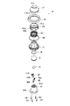
図17は第2ヘッド部7の断面図、図18は第2ヘッド部7の分解斜視図、図19は第2ヘッド部7を、ヘッド基台61のヘッド連結部61bに連結した状態を示す断面図、図20は第2ヘッド部7を、ヘッド基台61のヘッド連結部61bに連結した状態を示す外観図である。   17 is a cross-sectional view of the second head portion 7, FIG. 18 is an exploded perspective view of the second head portion 7, and FIG. 19 shows a state in which the second head portion 7 is connected to the head connecting portion 61b of the head base 61. FIG. 20 is an external view showing a state in which the second head portion 7 is connected to the head connecting portion 61 b of the head base 61.

第2ヘッド部7は、前述したように第2プローブヘッド13を備えており、第2プローブヘッド13の表面が人の肌に接触させる接触面13aとなり、接触面13aと反対側の背面13bに第2超音波振動子107を取り付けている。第2超音波振動子107は、前記した本体部1における振動子制御回路基板36から駆動電圧が印加されることで超音波振動し、これに伴い第2プローブヘッド13も超音波振動する。   The second head portion 7 includes the second probe head 13 as described above, and the surface of the second probe head 13 becomes a contact surface 13a that comes into contact with human skin, and the back surface 13b on the opposite side to the contact surface 13a. A second ultrasonic transducer 107 is attached. The second ultrasonic transducer 107 ultrasonically vibrates when a drive voltage is applied from the transducer control circuit board 36 in the main body 1, and the second probe head 13 also vibrates ultrasonically.

ここで第2プローブヘッド13の接触面13aの面積は、第1プローブヘッド9の接触面9aの面積より大きく形成している。   Here, the area of the contact surface 13 a of the second probe head 13 is formed larger than the area of the contact surface 9 a of the first probe head 9.

第2プローブヘッド13は、第2超音波振動子107を取り付けた側の外周縁に、外側に向けて突出するフランジ13cを設けている。   The second probe head 13 is provided with a flange 13c projecting outward on the outer peripheral edge on the side where the second ultrasonic transducer 107 is attached.

そして、このフランジ13cを覆うように、ほぼ円筒形状のプローブカバーとしてのヘッドカバー109を設けている。ヘッドカバー109は、先端にて内側に突出する屈曲部109aを第2プローブヘッド13の外周面に接触させ、屈曲部109aとフランジ13cとの間の空隙にシール部材としてのOリング111を設けている。   A head cover 109 as a substantially cylindrical probe cover is provided so as to cover the flange 13c. In the head cover 109, a bent portion 109a protruding inward at the tip is brought into contact with the outer peripheral surface of the second probe head 13, and an O-ring 111 as a seal member is provided in a gap between the bent portion 109a and the flange 13c. .

ヘッドカバー109は、上部が開口したヘッドベース113の上端が挿入された状態で、ヘッドベース113の係止突起113aが係止凹部109bに係止されてヘッドベース113に固定され、これら相互間にはシール部材としてのOリング115を介装している。   The head cover 109 is fixed to the head base 113 with the locking projections 113a of the head base 113 being locked to the locking recesses 109b with the upper end of the head base 113 opened at the top being inserted. An O-ring 115 as a seal member is interposed.

ヘッドベース113の内側には金具取付用リブ113bを形成し、この金具取付用リブ113bに陽極の接続金具117を取り付けるとともに、陰極の接続金具119を、接続金具117の外周側に位置する状態で取り付ける。接続金具117は、その先端の接触片117aが、第2超音波振動子107の背面に弾性的に押し付けられて接触し、後端の接続片117bにはリード線121の一端を接続する。   A metal fitting rib 113b is formed on the inner side of the head base 113, the anode connecting metal 117 is attached to the metal fitting mounting rib 113b, and the cathode connecting metal 119 is positioned on the outer peripheral side of the connecting metal 117. Install. The connection fitting 117 has a contact piece 117a at the tip thereof pressed against and in contact with the back surface of the second ultrasonic transducer 107, and one end of the lead wire 121 is connected to the connection piece 117b at the rear end.

一方、接続金具119は、その先端の接触片119aが、第2超音波振動子107より大径の第2プローブヘッド13の背面13bに弾性的に押し付けられて接触し、後端の接続片119bにはリード線123の一端を接続する。これら各リード線121,123の他端は、後述の図22に示すように、ボス部113d,後述するゴムカバー129及びヘッドストッパ131を貫通させて下方に延ばし、前述した本体回路基板35に接続する。   On the other hand, the contact piece 119a at the front end of the connection fitting 119 is elastically pressed and brought into contact with the back surface 13b of the second probe head 13 having a larger diameter than the second ultrasonic transducer 107, and the connection piece 119b at the rear end. Is connected to one end of a lead wire 123. As shown in FIG. 22 described later, the other end of each of the lead wires 121 and 123 extends downward through a boss portion 113d, a rubber cover 129 and a head stopper 131 described later, and is connected to the main circuit board 35 described above. To do.

上記した接続金具119は、図18に示すように、ほぼ環状に形成してその周縁に沿って前記した接触片119aを3個設けている。一方接続金具117は、接続金具119の内側に位置してほぼ半円弧形状を呈し、接触片117aを1個設けている。   As shown in FIG. 18, the connection fitting 119 described above is formed in a substantially annular shape and is provided with three contact pieces 119a described above along the periphery thereof. On the other hand, the connection fitting 117 is located inside the connection fitting 119 and has a substantially semicircular arc shape, and is provided with one contact piece 117a.

ヘッドベース113は、中心に位置するボス部113dの下端を、ベース部としてのスプリングベース127の中心に設けてある貫通孔127aに移動可能に挿入し、ボス部113dの下端面には、弾性体としてのゴムカバー129を、ヘッドストッパ131の板状部分131aを介してねじ133により固定する。なお、上記したスプリングベース127の外周面には、シール部材としてのOリング130を、ヘッド基台61のヘッド連結部61bとの間をシールするよう設けている。また、第2ヘッドリング74は、図19に示してあるヘッド基台61のヘッド連結部61bにねじ込むようにして固定されている。   The head base 113 is movably inserted into a through hole 127a provided at the center of a spring base 127 serving as a base portion at the lower end of the boss portion 113d positioned at the center. The rubber cover 129 is fixed by a screw 133 through the plate-like portion 131a of the head stopper 131. An O-ring 130 as a seal member is provided on the outer peripheral surface of the spring base 127 so as to seal between the head connecting portion 61 b of the head base 61. The second head ring 74 is fixed so as to be screwed into the head connecting portion 61b of the head base 61 shown in FIG.

ゴムカバー129の外周縁部付近には屈曲した環状の弾性変形部129aを設け、弾性変形部129aのさらに外側を、環状のゴムカバー押さえ135とスプリングベース127とで挟持した状態とし、この状態でねじ137により固定する。なお、ねじ137は、図18に示してあるように、ゴムカバー129の外周側にて周方向複数箇所(ここでは4箇所)にて下方に突出する凸部135aを利用して締結する。   A bent annular elastic deformation portion 129a is provided in the vicinity of the outer peripheral edge of the rubber cover 129, and the outer side of the elastic deformation portion 129a is sandwiched between the annular rubber cover press 135 and the spring base 127. Secure with screws 137. As shown in FIG. 18, the screw 137 is fastened by using convex portions 135 a that protrude downward at a plurality of circumferential locations (here, four locations) on the outer peripheral side of the rubber cover 129.

このとき、ヘッドストッパ131はゴムカバー押さえ135内に位置し、ボス部113dの下端面はスプリングベース127の貫通孔127aの下縁とほぼ同一位置となっている。   At this time, the head stopper 131 is located in the rubber cover holder 135, and the lower end surface of the boss portion 113d is substantially at the same position as the lower edge of the through hole 127a of the spring base 127.

スプリングベース127の内周側の上部には、ヘッドベース113のボス部113dが挿入される筒状のスプリングカバー139を設け、スプリングカバー139とボス部113dとの間に弾性手段としてのヘッドスプリング141を介装する。このヘッドスプリング141は、スプリングベース127に対しヘッドベース113を図17中で上方に向けて押し付けている。   A cylindrical spring cover 139 into which the boss 113d of the head base 113 is inserted is provided at the upper part on the inner peripheral side of the spring base 127, and a head spring 141 as an elastic means is provided between the spring cover 139 and the boss 113d. To intervene. The head spring 141 presses the head base 113 upward against the spring base 127 in FIG.

なお、スプリングカバー139の下端は、スプリングベース127の貫通孔127aに挿入され、この挿入状態でボス部113dとの間に隙間140を形成している。   The lower end of the spring cover 139 is inserted into the through hole 127a of the spring base 127, and a gap 140 is formed between the lower end of the spring cover 139 and the boss portion 113d in this inserted state.

以上の構成から、第2ヘッド部7は、該第2ヘッド部7が取り付けられるベース部であるスプリングベース127に対して直角方向(図17中で上下方向)に移動可能かつ、この直角方向の中心軸に対して揺動可能である。   From the above configuration, the second head portion 7 is movable in a perpendicular direction (vertical direction in FIG. 17) with respect to the spring base 127 that is a base portion to which the second head portion 7 is attached. It can swing with respect to the central axis.

この揺動動作が容易となるように、ヘッドベース113の下面は凸曲面113eに形成し、これに対応して第2ヘッドリング74のヘッドベース113に対向する面を凹曲面74aとしている。   In order to facilitate this swinging operation, the lower surface of the head base 113 is formed as a convex curved surface 113e, and the surface facing the head base 113 of the second head ring 74 is a concave curved surface 74a.

なお、スプリングカバー139及びゴムカバー129の材質は、EPDM,NBRまたはシリコンゴムである。また、ヘッドスプリング141は、前記したプローブヘッドスプリング83と同様に、SWPA,SWPB,SUS304,SUS304WPBなどの弾性を持つ材質で製作してあり、その内径は16.0mm程度である。   The material of the spring cover 139 and the rubber cover 129 is EPDM, NBR, or silicon rubber. Similarly to the probe head spring 83, the head spring 141 is made of an elastic material such as SWPA, SWPB, SUS304, SUS304WPB, and has an inner diameter of about 16.0 mm.

また、第2プローブヘッド13の接触面13aを肌に密着させたときのヘッドスプリング141の荷重は、5.0N程度でよいが、好ましくは2.0N〜4.0N、さらに好ましくは2.5N〜3.0Nであることが望ましい。ヘッドスプリング141の取付荷重は、0.5N〜2.0N程度でよいが、好ましくは1.0N〜1.5Nであることが望ましい。さらに、第2プローブヘッド13の接触面13aを肌に押し付けたときの移動量(フロート量)については,1.0mm〜7.0mm程度でよいが、好ましくは2.0mm〜6.0mm、さらに好ましくは3.0mm〜5.0mmであることが望ましい。   The load of the head spring 141 when the contact surface 13a of the second probe head 13 is brought into close contact with the skin may be about 5.0N, preferably 2.0N to 4.0N, more preferably 2.5N. It is desirable to be -3.0N. The mounting load of the head spring 141 may be about 0.5N to 2.0N, but preferably 1.0N to 1.5N. Furthermore, the movement amount (float amount) when the contact surface 13a of the second probe head 13 is pressed against the skin may be about 1.0 mm to 7.0 mm, preferably 2.0 mm to 6.0 mm, Preferably it is 3.0 mm-5.0 mm.

図21は、図17に対し、第2プローブヘッド13を肌に押し付けることでヘッドスプリング141が撓んで第2ヘッド部7がスプリングベース127に接近した状態を示し、図22は、図17に対し、第2ヘッド部7がスプリングベース127に対して揺動して傾いた状態を示している。但し図22は、図17とは別の角度から見た断面図である。   FIG. 21 shows a state where the second spring head 141 is bent by pressing the second probe head 13 against the skin, and the second head portion 7 approaches the spring base 127, and FIG. The second head portion 7 is shown in a state of being tilted while swinging with respect to the spring base 127. However, FIG. 22 is a cross-sectional view seen from an angle different from FIG.

前記したヘッドストッパ131は、その板状部分131aの下面に、振動モータ143を取り付けるモータ取付部131bを設けてあり、このモータ取付部131bに、ねじ145により基板125を取り付けている。この際、振動モータ143は、下部に配置した基板125と、モータ取付部131bに形成してある、振動モータ143の外形に合わせた凹状の円弧部131cとに挟持された状態となる。   The above-described head stopper 131 is provided with a motor attachment portion 131b for attaching the vibration motor 143 on the lower surface of the plate-like portion 131a, and the substrate 125 is attached to the motor attachment portion 131b with screws 145. At this time, the vibration motor 143 is sandwiched between a substrate 125 disposed in the lower portion and a concave arcuate portion 131c formed in the motor mounting portion 131b and adapted to the outer shape of the vibration motor 143.

上記した基板125には、振動モータ143に一端を接続しているモータリード線147の他端を接続する。さらに、この基板125と前記した本体回路基板35とをリード線151で接続する。   The other end of the motor lead wire 147 whose one end is connected to the vibration motor 143 is connected to the substrate 125 described above. Further, the board 125 and the main circuit board 35 are connected by a lead 151.

振動モータ143は、偏芯バランサ153を備えており、第2ヘッド部7全体に対してバイブレーションを発生させる機能を備えている。この振動モータ143の適正回転数は、好ましくは4400rpm〜7000rpm、さらに好ましくは5700rpm程度であることが望ましい。   The vibration motor 143 includes an eccentric balancer 153 and has a function of generating vibration for the entire second head unit 7. The appropriate rotation speed of the vibration motor 143 is preferably 4400 rpm to 7000 rpm, and more preferably about 5700 rpm.

図23は、上記したヘッドスプリング141に代わる弾性手段として例えば弾性をもつウレタンなどの樹脂からなる中空リング155を設けた例を示す、前記図17に対応する断面図である。   FIG. 23 is a cross-sectional view corresponding to FIG. 17 showing an example in which a hollow ring 155 made of a resin such as urethane having elasticity is provided as an elastic means in place of the head spring 141 described above.

すなわち、この例は、ヘッドスプリング141及びプリングカバー139に代えて円筒形状の中空リング155を設けており、その他の構成は図17のものと同様である。そのほか、ヘッドスプリング141に代わる弾性手段としてエアサスペンションも使用できる。   That is, in this example, a cylindrical hollow ring 155 is provided in place of the head spring 141 and the pulling cover 139, and other configurations are the same as those in FIG. In addition, an air suspension can be used as an elastic means instead of the head spring 141.

中空リング155を用いた場合には、ヘッドスプリング141を用いた場合に比較して部品点数を削減でき、簡素化した構造とすることができる。なお、中空リング155の材質は、ゴムカバー129と同様に、EPDM,NBRまたはシリコンゴムである。   When the hollow ring 155 is used, the number of parts can be reduced as compared with the case where the head spring 141 is used, and a simplified structure can be obtained. The material of the hollow ring 155 is EPDM, NBR, or silicon rubber, like the rubber cover 129.

また、前記図17に示したスプリングカバー139を廃止して、ヘッドベース113の凸曲面113eと第2ヘッドリング74の凹曲面74aとの少なくともいずれか一方に対し、ゴムやエストラマなどの弾性体を取り付けるか、あるいは樹脂などの弾性体を一体成形、もしくはゴム塗装やウレタン塗装を実施してもよい。   Also, the spring cover 139 shown in FIG. 17 is eliminated, and an elastic body such as rubber or elastomer is applied to at least one of the convex curved surface 113e of the head base 113 and the concave curved surface 74a of the second head ring 74. It may be attached, or an elastic body such as resin may be integrally formed, or rubber coating or urethane coating may be performed.

次に、上記のように構成した超音波美容器具の動作モードについて説明する。まず、図2に示すスイッチ15を1回押すと、本体電源が投入されたことを示すようにLED21が点灯し、鼻部のケアが可能な第1ヘッド部5の第1超音波振動子75が超音波振動して、この振動を第1プロープヘッド9に伝達する。   Next, the operation mode of the ultrasonic beauty instrument configured as described above will be described. First, when the switch 15 shown in FIG. 2 is pressed once, the LED 21 is turned on to indicate that the main unit power is turned on, and the first ultrasonic transducer 75 of the first head unit 5 capable of caring the nose. Vibrates ultrasonically and transmits this vibration to the first probe head 9.

スイッチ15を1回押した後、5分が経過した場合には、本体電源が自動的にOFFとなるが、5分以内にもう一度スイッチ15を押すと、今まで動作していた第1プロープヘッド9の超音波振動が停止し、顔部のケアが可能な第2ヘッド部7の第2超音波振動子107が超音波振動して、この振動を第2プロープヘッド13に伝達し、同時に振動モータ143も駆動する。このときLED23が点灯する一方、LED21は消灯する。   If 5 minutes have passed after the switch 15 is pressed once, the main power is automatically turned off. If the switch 15 is pressed again within 5 minutes, the first probe head that has been operating until now The ultrasonic vibration 9 stops and the second ultrasonic transducer 107 of the second head unit 7 capable of caring for the face ultrasonically vibrates, and this vibration is transmitted to the second probe head 13 and simultaneously vibrates. The motor 143 is also driven. At this time, the LED 23 is turned on, while the LED 21 is turned off.

この状態で6分が経過した場合には、本体電源が自動的にOFFとなるが、6分以内にもう一度スイッチ15を押すと、振動モータ143が停止し、第2超音波振動子107のみが動作して第2プロープヘッド13の超音波振動を継続させる。このとき、LED25が点灯する一方、LED23は消灯する。   If 6 minutes elapses in this state, the main body power supply is automatically turned off. However, if the switch 15 is pressed again within 6 minutes, the vibration motor 143 stops and only the second ultrasonic transducer 107 is turned on. It operates to continue the ultrasonic vibration of the second probe head 13. At this time, the LED 25 is turned on, while the LED 23 is turned off.

この状態でさらにスイッチ15を一度押すか、または第2プロープヘッド13を2分30秒間肌に対して移動負荷を与えない状態でいる、あるいは10分間第2プロープヘッド13を肌に押し付けて肌ケアを行うと、本体電源がオフとなってLED25が消灯する。   In this state, the switch 15 is further pressed once, or the second probe head 13 is in a state where no movement load is applied to the skin for 2 minutes and 30 seconds, or the second probe head 13 is pressed against the skin for 10 minutes for skin care. Is performed, the main body power is turned off and the LED 25 is turned off.

このように本超音波美容器具では、本体部1に設けたスイッチ15の操作によって第1ヘッド部5と第2ヘッド部7とを選択的に動作させることが可能となる。   As described above, in this ultrasonic beauty instrument, the first head unit 5 and the second head unit 7 can be selectively operated by operating the switch 15 provided in the main body unit 1.

また、本実施形態においては、第1プローブヘッド9または第2プローブヘッド13を作動させるときに、振動子制御回路基板36における同一の制御回路から同一の超音波周波数を供給する構成としているので、器具全体の小型化を達成することができる。   Further, in the present embodiment, when the first probe head 9 or the second probe head 13 is operated, the same ultrasonic frequency is supplied from the same control circuit in the transducer control circuit board 36. Miniaturization of the entire device can be achieved.

さらに、本超音波美容器具によれば、図1に示すように、全体をY字形状とすることで、使用者が本体部1を自然に把持した状態で、第1,第2ヘッド部5,7の先端に設けた第1,第2プローブヘッド9,13の接触面9a,13aを肌表面に接触させやすくなり、T字形状とした場合に比較して使い勝手が向上する。   Furthermore, according to the present ultrasonic beauty instrument, as shown in FIG. 1, the first and second head parts 5 are formed in a state where the user naturally holds the main body part 1 by making the whole into a Y shape. The contact surfaces 9a and 13a of the first and second probe heads 9 and 13 provided at the distal ends of the first and second probes 7 and 7 can be easily brought into contact with the skin surface.

次に、図6に示す第1ヘッド部5を使用して鼻部のケアを行う動作について説明する。本体部1を手に持って、前述したようにスイッチ15を1回押すことで、第1プローブヘッド9が超音波振動する。この状態で第1ヘッド部5を鼻の上部(眉間の直下付近)に接近させ押し付ける。この際アタッチメント11の切欠11aが下部に位置しており、この状態で一定以上の押し付け荷重をアタッチメント11を介して付与すると、アタッチメント11がプローブヘッドスプリング83の弾性力に抗しながら後退する。   Next, the operation for caring for the nose using the first head unit 5 shown in FIG. 6 will be described. The first probe head 9 is ultrasonically vibrated by holding the main body 1 and pressing the switch 15 once as described above. In this state, the first head unit 5 is moved closer to the upper part of the nose (near the area between the eyebrows) and pressed. At this time, the notch 11 a of the attachment 11 is positioned at the lower part. When a pressing load of a certain level or more is applied through the attachment 11 in this state, the attachment 11 moves backward while resisting the elastic force of the probe head spring 83.

ここでアタッチメント11の接触部11aの内径は17.0mm、外径は20.0mmである。一例としてアタッチメント11が1.5mm後退したときの断面図を図9に示す。アタッチメント11及び超音波振動が付与されている第1プローブヘッド9が肌に接触し図9のような状態にあるときに、第1プローブヘッド9の超音波振動により角栓や毛穴の汚れ成分が軟化し、これらを肌表面に押し出すことができる。   Here, the inner diameter of the contact portion 11a of the attachment 11 is 17.0 mm, and the outer diameter is 20.0 mm. As an example, FIG. 9 shows a cross-sectional view when the attachment 11 is retracted 1.5 mm. When the attachment 11 and the first probe head 9 to which ultrasonic vibration is applied are in contact with the skin and are in a state as shown in FIG. 9, dirt components of the square plugs and pores are caused by the ultrasonic vibration of the first probe head 9. Softens and can push them to the skin surface.

この状態で、本器具を鼻の先端側に向けて徐々にスライド移動させることで、上記押し出されて軟化した角栓や毛穴の汚れ成分をアタッチメント11の内周縁によって剥ぎ取るようにして除去する。この際アタッチメント11には進行方向前方側に切欠11aがあり、切欠11aと反対側の鼻に接触する内周縁をR形状としているので、肌への傷つきを軽減した状態で鼻のケアを行うことができ、同時に、超音波振動により除去後の毛穴の引き締め効果も得られる。   In this state, the instrument is gradually slid toward the tip of the nose, so that the pushed-out and softened plugs and dirt components of the pores are removed by peeling off the inner periphery of the attachment 11. At this time, the attachment 11 has a notch 11a on the front side in the advancing direction, and the inner peripheral edge that contacts the nose on the opposite side of the notch 11a has an R shape. At the same time, the effect of tightening the pores after removal can be obtained by ultrasonic vibration.

また、アタッチメント11は円形としているので、移動方向を変化させても問題ない。このようなアタッチメント11は、取り外しが可能なので、取り外した状態で単体での水洗いができ、掃除性が向上して常に清潔な状態で使用することができる。   Moreover, since the attachment 11 is circular, there is no problem even if the moving direction is changed. Since such an attachment 11 can be removed, it can be washed with water in a detached state, and can be used in a clean state with improved cleanability.

なお、このアタッチメント11の押し付け時の後退量(フロート量)としては、最大で2.0mm程度が好ましく、その最大後退時には、プローブカバー77の先端にアタッチメント11の内面が当接部Pにて当接するものとする。また、使用時における超音波振動子9の接触面9aからの突出量αは、0.3mm以上、好ましくは0.5mmであることが望ましい。   The retraction amount (float amount) at the time of pressing the attachment 11 is preferably about 2.0 mm at the maximum. At the maximum retraction, the inner surface of the attachment 11 contacts the tip of the probe cover 77 at the contact portion P. It shall touch. In addition, the protrusion amount α from the contact surface 9a of the ultrasonic transducer 9 during use is desirably 0.3 mm or more, and preferably 0.5 mm.

フロート量が2.0mmを超える場合には、肌に押し付けるときのストロークが大きくなって使い勝手が悪くなり、また使用時での突出量αが0.5mmを超える場合には、第1超音波振動子9が肌に接触しにくくなる。   When the float amount exceeds 2.0 mm, the stroke when pressed against the skin becomes large and usability deteriorates. When the projection amount α during use exceeds 0.5 mm, the first ultrasonic vibration The child 9 becomes difficult to contact the skin.

また、アタッチメント11の押し付け荷重としては、好ましくは0.686N〜1.078N、さらに好ましくは、0.784N〜0.98Nが望ましい。   In addition, the pressing load of the attachment 11 is preferably 0.686N to 1.078N, and more preferably 0.784N to 0.98N.

また、上記したアタッチメント11は、プローブヘッドスプリング83によってフロート可能な構造としているが、固定構造としてもよく、また円形に限らず板状のものでもよい。   The attachment 11 described above has a structure that can be floated by the probe head spring 83. However, the attachment 11 may have a fixed structure, and may have a plate shape instead of a circular shape.

次に、図17に示す第2ヘッド部7を使用して顔部のケアを行う動作について説明する。前述したように第1ヘッド部5が作動している状態で、スイッチ15をもう1回押すことで、第2プローブヘッド13が超音波振動するとともに、振動モータ143が作動してバイブレーション機能が発生する。この状態で第2ヘッド部7を顔部の例えば頬に接近させ押し付ける。   Next, the operation of performing facial care using the second head unit 7 shown in FIG. 17 will be described. As described above, when the switch 15 is pressed once again while the first head unit 5 is operating, the second probe head 13 is ultrasonically vibrated and the vibration motor 143 is activated to generate a vibration function. To do. In this state, the second head portion 7 is brought close to, for example, the cheek of the face portion and pressed.

上記した第2プローブヘッド13の超音波振動と、振動モータ143のバイブレーション機能により、毛穴に張りを与えて血行を促進させ、コラーゲンの生成を促進し、肌に張りが出ることで、毛穴を目立たなくなるようにする。   By applying the ultrasonic vibration of the second probe head 13 and the vibration function of the vibration motor 143, the pores are stretched to promote blood circulation, promote the production of collagen, and the skin is stretched to make the pores conspicuous. Make it disappear.

ここで第2プローブヘッド13を肌に対して一定以上の押し付け荷重を付与すると、図21に一例を示すように、ヘッドスプリング141が撓み第2プローブヘッド13が後退する。このとき、ヘッドベース113も一体となって後退し、そのボス部113dがゴムカバー129を撓ませ、さらにヘッドストッパ131や振動モータ143も一体となって後退する。   Here, when a certain load or more is applied to the second probe head 13 against the skin, the head spring 141 is bent and the second probe head 13 is retracted as shown in FIG. At this time, the head base 113 is also retracted integrally, the boss portion 113d bends the rubber cover 129, and the head stopper 131 and the vibration motor 143 are also retracted integrally.

また、本器具を肌表面に沿って移動させる際などには、図22に示すように、上記一体となって後退した部分全体が傾くことで、第2プローブヘッド13の接触面13aを肌表面に常に自然な状態で接触させることができる。   Further, when the device is moved along the skin surface, as shown in FIG. 22, the whole of the integrally retracted portion is inclined so that the contact surface 13 a of the second probe head 13 is moved to the skin surface. Can always be in a natural state.

この際、EPDMなどの弾性体で構成してあるスプリングカバー139を設けているので、ヘッドベース113とスプリングベース127とが干渉しても、振動モータ143による横方向振動をスプリングカバー139が吸収し、異音発生を防止することができる。したがって、耳障りな音などによる不快感なく肌ケアを行うことができる。   At this time, since the spring cover 139 made of an elastic material such as EPDM is provided, even if the head base 113 and the spring base 127 interfere with each other, the spring cover 139 absorbs the lateral vibration by the vibration motor 143. The generation of abnormal noise can be prevented. Therefore, skin care can be performed without an uncomfortable feeling due to unpleasant sounds.

また、前述した第1ヘッド部5は、図6に示すように、接続金具95,97を取り付けたプローブ基台91上に第1プローブヘッド9を配置し、この組立部品にプローブカバー77を被せ、プローブ基台91とプローブカバー77とをねじ93により固定することで、第1プローブヘッド9がプローブ基台91に押し付けられ、これにより接続金具95,97の各接触片95a,97aが撓んで第1プローブヘッド9のフランジ9dの下面及び第2超音波振動子75にそれぞれ接触する。このため、この接触状態が良好に保たれ、本体回路基板35からの電気信号を第1超音波振動子75に安定して伝達させることができる。   Further, as shown in FIG. 6, in the first head portion 5 described above, the first probe head 9 is arranged on the probe base 91 to which the connection fittings 95 and 97 are attached, and the probe cover 77 is put on this assembly part. By fixing the probe base 91 and the probe cover 77 with the screws 93, the first probe head 9 is pressed against the probe base 91, whereby the contact pieces 95a and 97a of the connection fittings 95 and 97 are bent. The lower surface of the flange 9d of the first probe head 9 and the second ultrasonic transducer 75 are in contact with each other. For this reason, this contact state is maintained well, and the electrical signal from the main body circuit board 35 can be stably transmitted to the first ultrasonic transducer 75.

また、これら各接続金具95,97は、図15に示すように十字形状の絶縁リブ91gによって隔離され、互いの接触を確実に回避することができ、接続金具95,97同士の短絡を防止して制御回路の破損などの不具合を防止することができる。   Further, as shown in FIG. 15, each of these connection fittings 95 and 97 is isolated by a cross-shaped insulating rib 91g, so that contact with each other can be reliably avoided, and a short circuit between the connection fittings 95 and 97 is prevented. Thus, problems such as breakage of the control circuit can be prevented.

上記した第1ヘッド部5において、ジェルなどの液体を用いて肌ケアを行うときには、この液体が第1プローブヘッド9やアタッチメント11を伝わって内部に侵入しようとするが、Oリング79,89が、この侵入を阻止して良好な使用状態を確保することができる。また、このような防水構造を備えているので、第1プローブヘッド9やそれに取り巻く部品に付着した液体や固体を水洗いすることができ、また本体制御回路の破損を防止することができる。   In the first head portion 5 described above, when skin care is performed using a liquid such as a gel, the liquid tries to enter the first probe head 9 and the attachment 11, but the O-rings 79 and 89 Therefore, it is possible to prevent this intrusion and ensure a good use state. Further, since such a waterproof structure is provided, the liquid or solid adhering to the first probe head 9 or the parts surrounding it can be washed with water, and the main body control circuit can be prevented from being damaged.

一方、第2ヘッド部7においても、ジェルなどの液体を用いて肌ケアを行うときには、この液体が第2プローブヘッド13やヘッドカバー109を伝わって内部に侵入しようとするが、Oリング111,115,ゴムカバー129及びOリング130がこの侵入を阻止して良好な使用状態を確保することができる。また、このような防水構造を備えているので、第2プローブヘッド13やそれに取り巻く部品に付着した液体や固体を水洗いすることができ、また本体制御回路の破損を防止することができる。   On the other hand, when skin care is performed using the liquid such as gel in the second head portion 7, the liquid tries to enter the second probe head 13 and the head cover 109, but the O-rings 111 and 115. The rubber cover 129 and the O-ring 130 can prevent this intrusion and ensure a good use state. Further, since such a waterproof structure is provided, the liquid or solid adhering to the second probe head 13 or parts surrounding it can be washed with water, and damage to the main body control circuit can be prevented.

さらに、本器具を用いてジェルなどの液体を用いて肌ケアを行うときには、この液体が、図5に示すヘッドケース65,67やハウジング31を伝わって本体内部に侵入しようとするが、本体Oリング63,スイッチゴム51,下カバーOリング57により、この侵入を阻止して良好な使用状態を確保することができる。   Further, when skin care is performed using a liquid such as a gel using this instrument, the liquid tries to enter the main body through the head cases 65 and 67 and the housing 31 shown in FIG. The ring 63, the switch rubber 51, and the lower cover O-ring 57 can prevent this intrusion and ensure a good use state.

したがって、この場合にも本体部1に取り巻く部品に付着した液体や固体を水洗いすることができ、また本体制御回路の破損を防止することができる。   Therefore, in this case as well, liquids and solids adhering to the parts surrounding the main body 1 can be washed with water, and damage to the main body control circuit can be prevented.

また、図17に示す第2ヘッド部7においては、ヘッドベース113のボス部113dに、振動モータ143及び基板125を取り付けるヘッドストッパ131を固定し、これらが一体となってスプリングベース127に対して前後移動や揺動するので、振動モータ143と基板125とを接続する、比較的細く形成してあるモータリード線147の破断を防止することができる。   In the second head portion 7 shown in FIG. 17, the head stopper 131 for attaching the vibration motor 143 and the substrate 125 is fixed to the boss portion 113 d of the head base 113, and these are integrated with the spring base 127. Since it moves back and forth and swings, it is possible to prevent breakage of the relatively thin motor lead wire 147 connecting the vibration motor 143 and the substrate 125.

なお、上記振動モータ143と基板125と接続するモータリード線147に代えて、振動モータ143と基板125にそれぞれ設けた接続金具同士の接触や、振動モータ143に設けた接続金具を基板125側のメッキされた接点に接触させる構成でも構わない。   In place of the motor lead wire 147 connecting the vibration motor 143 and the substrate 125, contact between the connection fittings provided on the vibration motor 143 and the substrate 125, or connection fitting provided on the vibration motor 143 on the substrate 125 side is provided. It may be configured to contact the plated contact.

本発明の一実施形態を示す超音波美容器具の正面図である。It is a front view of the ultrasonic beauty instrument which shows one Embodiment of this invention. 図1の背面図である。It is a rear view of FIG. 図1の超音波美容器具にキャップを装着した状態を示す正面図である。It is a front view which shows the state which mounted | wore the ultrasonic beauty instrument of FIG. 図1の超音波美容器具の分解斜視図である。It is a disassembled perspective view of the ultrasonic beauty instrument of FIG. 図2のA−A断面図である。It is AA sectional drawing of FIG. 第1ヘッド部の断面図である。It is sectional drawing of a 1st head part. 第1ヘッド部の分解斜視図である。It is a disassembled perspective view of a 1st head part. 第1ヘッド部を、ヘッド基台に連結した状態を示す断面図である。It is sectional drawing which shows the state which connected the 1st head part to the head base. 図6に対しアタッチメントが後退移動した状態を示す断面図である。It is sectional drawing which shows the state which the attachment moved backward with respect to FIG. アタッチメントを取り外した状態の第1ヘッド部の正面図である。It is a front view of the 1st head part in the state where an attachment was removed. 図6に対し第1ヘッドリング,プローブスプリングカバー,プローブヘッドスプリング及びアタッチメントを省略した状態の正面図である。FIG. 7 is a front view showing a state in which the first head ring, the probe spring cover, the probe head spring, and the attachment are omitted from FIG. 6. 図11に対応する正面断面図である。It is front sectional drawing corresponding to FIG. 図12のB−B断面図である。It is BB sectional drawing of FIG. 図13におけるヘッド基台の平面図である。FIG. 14 is a plan view of the head base in FIG. 13. 図13におけるヘッド基台の底面図である。FIG. 14 is a bottom view of the head base in FIG. 13. 接続金具に代えてコイルばねを設けた例を示す、図12に対応する断面図である。It is sectional drawing corresponding to FIG. 12 which shows the example which replaced with the connection metal fitting and provided the coil spring. 第2ヘッド部の断面図である。It is sectional drawing of a 2nd head part. 第2ヘッド部の分解斜視図である。It is a disassembled perspective view of a 2nd head part. 第2ヘッド部を、ヘッド基台に連結した状態を示す断面図である。It is sectional drawing which shows the state which connected the 2nd head part to the head base. 第2ヘッド部をヘッド基台に連結した状態を示す外観図である。It is an external view which shows the state which connected the 2nd head part to the head base. 図17に対し、第2ヘッド部が後退移動した状態を示す断面図である。FIG. 18 is a cross-sectional view illustrating a state in which the second head unit is moved backward with respect to FIG. 17. 図17に対し、第2ヘッド部が揺動して傾いた状態を示す断面図である。FIG. 18 is a cross-sectional view illustrating a state in which the second head unit is swung and inclined with respect to FIG. 17. ヘッドスプリングに代わる中空リングを設けた例を示す、図17に対応する断面図である。It is sectional drawing corresponding to FIG. 17 which shows the example which provided the hollow ring replaced with a head spring.

符号の説明Explanation of symbols

1 本体部
5 第1ヘッド部
7 第2ヘッド部
9 第1プローブヘッド
9a 第1プローブヘッドの接触面
13 第2プローブヘッド
13a 第2プローブヘッドの接触面
15 スイッチ(スイッチ部)
31 本体部のハウジング
36 制御回路を備えた振動子制御回路基板
51 スイッチゴム(シール部材)
53 端部カバー
57 下カバーOリング
63 本体Oリング(シール部材)
75 第1超音波振動子
79,89 Oリング(シール部材)
107 第2超音波振動子
109 ヘッドカバー(プローブカバー)
111,115,130 Oリング(シール部材)
127 スプリングベース(ベース部)
127a スプリングベースの貫通孔(ベース部中心の貫通孔)
129 ゴムカバー(弾性体)
141 ヘッドスプリング(弾性手段)
DESCRIPTION OF SYMBOLS 1 Main-body part 5 1st head part 7 2nd head part 9 1st probe head 9a Contact surface of 1st probe head 13 2nd probe head 13a Contact surface of 2nd probe head 15 Switch (switch part)
31 Housing for Main Body 36 Vibrator Control Circuit Board with Control Circuit 51 Switch Rubber (Seal Member)
53 End cover 57 Lower cover O-ring 63 Body O-ring (seal member)
75 First ultrasonic transducer 79, 89 O-ring (seal member)
107 Second ultrasonic transducer
109 Head cover (probe cover)
111, 115, 130 O-ring (seal member)
127 Spring base (base part)
127a Spring base through hole (through hole at the center of the base)
129 Rubber cover (elastic body)
141 Head spring (elastic means)

Claims (11)

超音波振動子から付与される超音波振動を、プローブヘッドを介して肌表面に伝達させる超音波美容器具において、本体部に対し、導電材料からなる前記プローブヘッドを備えたヘッド部を複数設け、この複数のヘッド部の、前記肌表面に接触させるプローブヘッドの接触面の大きさを互いに異ならせ、前記各プローブヘッドに対応して設けたそれぞれの超音波振動子に対し、同一の制御回路から同一の超音波周波数を供給する構成とし、前記複数のヘッド部は、それぞれの前記超音波振動子が対応する前記各プローブヘッドの背面に取り付けられるとともに、前記超音波振動子の前記プローブヘッドと反対側に位置する基台と、この基台の外周側に位置して該基台とで前記プローブヘッドの外周縁を挟持固定するプローブカバーとを備え、かつ前記複数のヘッド部は、前記制御回路に一端が接続される一対のリード線の各他端を、前記基台に取り付けた一対の接続金具の一端にそれぞれ接続し、前記プローブカバーと前記基台とで前記プローブヘッドの外周縁を挟持固定した状態で、前記各接続金具の他端を前記超音波振動子の背面と前記プローブヘッドの背面とにそれぞれ押し付けて接続することを特徴とする超音波美容器具。 In an ultrasonic beauty instrument that transmits ultrasonic vibration applied from an ultrasonic transducer to the skin surface via a probe head, a plurality of head portions including the probe head made of a conductive material are provided on the main body portion, The contact surfaces of the probe heads to be brought into contact with the skin surface of the plurality of head portions are different from each other, and for each ultrasonic transducer provided corresponding to each probe head, from the same control circuit The plurality of head portions are attached to the back surfaces of the probe heads to which the ultrasonic transducers correspond, and are opposite to the probe heads of the ultrasonic transducers. A base that is positioned on the side, and a probe cover that is positioned on the outer peripheral side of the base and sandwiches and fixes the outer periphery of the probe head with the base. The plurality of head portions respectively connect the other ends of a pair of lead wires, one end of which is connected to the control circuit, to one end of a pair of connection fittings attached to the base, and the probe cover and the base In a state in which the outer peripheral edge of the probe head is sandwiched and fixed by a base, the other end of each connection fitting is pressed and connected to the back surface of the ultrasonic transducer and the back surface of the probe head, respectively. Sonic beauty equipment. 前記本体部に対して前記ヘッド部を二つ設け、この二つのヘッド部と前記本体部とで正面視でY字形状となるよう形成したことを特徴とする請求項1に記載の超音波美容器具。   The ultrasonic beauty according to claim 1, wherein two head parts are provided for the main body part, and the two head parts and the main body part are formed in a Y shape in a front view. Instruments. 前記二つのヘッド部のうち一方は、該ヘッド部が取り付けられるベース部に対して直角方向に移動可能かつ、この直角方向の中心軸に対して揺動可能であることを特徴とする請求項2に記載の超音波美容器具。   3. One of the two head portions is movable in a direction perpendicular to a base portion to which the head portion is attached, and is swingable with respect to a central axis in the perpendicular direction. The ultrasonic beauty instrument described in. 前記二つのヘッド部のうち一方は、前記ベース部に対し弾性手段を介して前記直角方向に移動可能に支持されるとともに、前記ベース部中心の貫通孔に基端部を移動可能に挿入して前記ベース部に弾性体を介して取り付けたことを特徴とする請求項3に記載の超音波美容器具。   One of the two head parts is supported so as to be movable in the perpendicular direction via elastic means with respect to the base part, and a base end part is movably inserted into a through hole at the center of the base part. The ultrasonic beauty instrument according to claim 3, wherein the ultrasonic beauty instrument is attached to the base portion via an elastic body. 前記複数のヘッド部は、防水構造を備えていることを特徴とする請求項1ないし4のいずれか1項に記載の超音波美容器具。   The ultrasonic beauty instrument according to claim 1, wherein the plurality of head portions have a waterproof structure. 前記二つのヘッド部のうち一方は、前記プローブヘッドと該プローブヘッドの外周縁を固定するプローブカバーの先端側との間にシール部材を設けて防水構造としたことを特徴とする請求項5に記載の超音波美容器具。   6. One of the two head portions is provided with a waterproof structure by providing a seal member between the probe head and a distal end side of a probe cover that fixes an outer peripheral edge of the probe head. The ultrasonic beauty instrument described. 前記プローブカバーの基端側にヘッドベースを設け、このヘッドベースと前記プローブカバーとの間にシール部材を設けて防水構造としたことを特徴とする請求項6に記載の超音波美容器具。   The ultrasonic beauty instrument according to claim 6, wherein a head base is provided on a proximal end side of the probe cover, and a sealing member is provided between the head base and the probe cover to form a waterproof structure. 前記二つのヘッド部のうち一方は、該ヘッド部が取り付けられるベース部に対して直角方向に移動可能かつ、この直角方向の中心軸に対して揺動可能であり、前記ベース部と、該ベース部を取り付ける前記本体部側との間にシール部材を設けて防水構造としたことを特徴とする請求項5ないし7のいずれか1項に記載の超音波美容器具。   One of the two head portions is movable in a direction perpendicular to a base portion to which the head portion is attached and is swingable with respect to a central axis in the perpendicular direction. The base portion and the base The ultrasonic beauty instrument according to any one of claims 5 to 7, wherein a sealing member is provided between the main body part side to which the part is attached and a waterproof structure is provided. 前記二つのヘッド部のうち他方は、前記プローブヘッドと該プローブヘッドの外周縁を固定するプローブカバーの先端側との間及び、前記プローブカバーの基端側と、この基端側を取り付ける前記本体部側との間にシール部材を設けて防水構造としたことを特徴とする請求項5ないし8のいずれか1項に記載の超音波美容器具。   The other of the two head portions is between the probe head and the distal end side of the probe cover that fixes the outer peripheral edge of the probe head, and the proximal end side of the probe cover and the main body to which the proximal end side is attached The ultrasonic beauty instrument according to any one of claims 5 to 8, wherein a sealing member is provided between the first side and the second side to form a waterproof structure. 前記本体部の前記ヘッド部と反対側の端部に端部カバーを設け、この端部カバーと前記本体部のハウジングと間にシール部材を設けて防水構造とするとともに、前記本体部に設けたスイッチ部にシール部材を設けて防水構造としたことを特徴とする請求項1ないし9のいずれか1項に記載の超音波美容器具。   An end cover is provided at an end of the main body portion opposite to the head portion, and a sealing member is provided between the end cover and the housing of the main body portion to provide a waterproof structure, and provided in the main body portion. The ultrasonic beauty instrument according to any one of claims 1 to 9, wherein a sealing member is provided in the switch portion to form a waterproof structure. 前記本体部に設けたスイッチ部の操作によって前記複数のヘッド部を選択的に動作させることを特徴とする請求項1ないし10のいずれか1項に記載の超音波美容器具。   The ultrasonic beauty instrument according to any one of claims 1 to 10, wherein the plurality of head parts are selectively operated by operating a switch part provided in the main body part.
JP2007255220A 2007-09-28 2007-09-28 Ultrasonic beauty equipment Active JP4416028B2 (en)

Priority Applications (5)

Application Number Priority Date Filing Date Title
JP2007255220A JP4416028B2 (en) 2007-09-28 2007-09-28 Ultrasonic beauty equipment
EP08016708A EP2042148A1 (en) 2007-09-28 2008-09-23 Ultrasonic esthetic implement
CN2008101687097A CN101396592B (en) 2007-09-28 2008-09-26 Ultrasonic cosmetic device
RU2008138461/14A RU2392918C1 (en) 2007-09-28 2008-09-26 Ultrasonic cosmetic device
HK09105767.1A HK1126702A1 (en) 2007-09-28 2009-06-26 Ultrasoni esthetic implement

Applications Claiming Priority (1)

Application Number Priority Date Filing Date Title
JP2007255220A JP4416028B2 (en) 2007-09-28 2007-09-28 Ultrasonic beauty equipment

Publications (2)

Publication Number Publication Date
JP2009082377A JP2009082377A (en) 2009-04-23
JP4416028B2 true JP4416028B2 (en) 2010-02-17

Family

ID=40076736

Family Applications (1)

Application Number Title Priority Date Filing Date
JP2007255220A Active JP4416028B2 (en) 2007-09-28 2007-09-28 Ultrasonic beauty equipment

Country Status (5)

Country Link
EP (1) EP2042148A1 (en)
JP (1) JP4416028B2 (en)
CN (1) CN101396592B (en)
HK (1) HK1126702A1 (en)
RU (1) RU2392918C1 (en)

Cited By (3)

* Cited by examiner, † Cited by third party
Publication number Priority date Publication date Assignee Title
EP3415198A1 (en) 2017-06-13 2018-12-19 Panasonic Intellectual Property Management Co., Ltd. Beauty apparatus
EP3446745A1 (en) 2017-08-24 2019-02-27 Panasonic Intellectual Property Management Co., Ltd. Beauty apparatus
EP3449890A1 (en) 2017-08-29 2019-03-06 Panasonic Intellectual Property Management Co., Ltd. Beauty apparatus

Families Citing this family (5)

* Cited by examiner, † Cited by third party
Publication number Priority date Publication date Assignee Title
AU2012372226B2 (en) * 2012-03-05 2015-07-09 Bomtech Electronics Co., Ltd. Skincare apparatus
JP6101299B2 (en) * 2015-03-31 2017-03-22 日立マクセル株式会社 Beauty equipment
CN107440584A (en) * 2017-09-08 2017-12-08 小熊电器股份有限公司 A kind of relocatable face cleaning instrument scrub body and face cleaning instrument
CN108814937B (en) * 2018-04-29 2020-10-20 乐清市川嘉电气科技有限公司 Skin care device
KR102324257B1 (en) * 2021-06-15 2021-11-10 엘지전자 주식회사 Body cleanser

Family Cites Families (7)

* Cited by examiner, † Cited by third party
Publication number Priority date Publication date Assignee Title
FR2706293A1 (en) 1993-06-14 1994-12-23 Satelec Sa Portable massage and cleaning machine with ultrasonic vibration.
US5558623A (en) 1995-03-29 1996-09-24 Rich-Mar Corporation Therapeutic ultrasonic device
JP2000233005A (en) * 1999-02-16 2000-08-29 Ya Man Ltd Vibration probe of ultrasonic cosmetic unit
JP2001252323A (en) 2000-03-14 2001-09-18 Katsutoshi Masuda Aesthetic implement
EP1430863A4 (en) * 2001-09-21 2006-11-22 Ya Man Ltd Ultrasonic beauty treatment probe
JP2006034651A (en) * 2004-07-28 2006-02-09 Japan Giyaruzu:Kk Ultrasonic beauty implement
JP4483605B2 (en) * 2005-01-31 2010-06-16 パナソニック電工株式会社 Skin care equipment

Cited By (3)

* Cited by examiner, † Cited by third party
Publication number Priority date Publication date Assignee Title
EP3415198A1 (en) 2017-06-13 2018-12-19 Panasonic Intellectual Property Management Co., Ltd. Beauty apparatus
EP3446745A1 (en) 2017-08-24 2019-02-27 Panasonic Intellectual Property Management Co., Ltd. Beauty apparatus
EP3449890A1 (en) 2017-08-29 2019-03-06 Panasonic Intellectual Property Management Co., Ltd. Beauty apparatus

Also Published As

Publication number Publication date
EP2042148A1 (en) 2009-04-01
RU2392918C1 (en) 2010-06-27
JP2009082377A (en) 2009-04-23
HK1126702A1 (en) 2009-09-11
RU2008138461A (en) 2010-04-10
CN101396592B (en) 2011-09-21
CN101396592A (en) 2009-04-01

Similar Documents

Publication Publication Date Title
JP4416027B2 (en) Ultrasonic beauty equipment
JP4400665B2 (en) Ultrasonic beauty equipment
JP4416028B2 (en) Ultrasonic beauty equipment
RU2371164C2 (en) Skin treatment device
US7282036B2 (en) Cosmetic device having vibrator
JP4483605B2 (en) Skin care equipment
CN109621187A (en) Low frequency massage host and adjustable cervical massage device
JP4840317B2 (en) Ultrasonic beauty equipment
CN115474761A (en) Body cleaning instrument
CN109907964A (en) A kind of massage head and neck massager
JP2010035807A (en) Electric hairbrush
US7716771B2 (en) Common toothbrush usable electronic toothbrush
CN215025427U (en) Negative pressure ultrasonic beautifying device
CN215779809U (en) Eye massager
JP6796418B2 (en) Cosmetology device
JP4490140B2 (en) Head fitting
JP7117714B2 (en) portable cleaning equipment
JP7618923B2 (en) Beauty Equipment
JP4748134B2 (en) Ultrasonic generator and beauty apparatus equipped with the same
JP2005124893A (en) Cosmetic appliance
CN220801435U (en) Massage device and massage instrument with same
KR20250018647A (en) Handheld ultrasonic generator capable of replacing the ultrasonic generator
CN113101550A (en) A negative pressure ultrasonic beauty device
KR20250020886A (en) Replaceable Ultrasonic Stimulator
CN114073637A (en) Massage device

Legal Events

Date Code Title Description
A621 Written request for application examination

Free format text: JAPANESE INTERMEDIATE CODE: A621

Effective date: 20090410

A131 Notification of reasons for refusal

Free format text: JAPANESE INTERMEDIATE CODE: A131

Effective date: 20090728

A521 Written amendment

Free format text: JAPANESE INTERMEDIATE CODE: A523

Effective date: 20090915

TRDD Decision of grant or rejection written
A01 Written decision to grant a patent or to grant a registration (utility model)

Free format text: JAPANESE INTERMEDIATE CODE: A01

Effective date: 20091104

A01 Written decision to grant a patent or to grant a registration (utility model)

Free format text: JAPANESE INTERMEDIATE CODE: A01

R150 Certificate of patent or registration of utility model

Ref document number: 4416028

Country of ref document: JP

Free format text: JAPANESE INTERMEDIATE CODE: R150

Free format text: JAPANESE INTERMEDIATE CODE: R150

A61 First payment of annual fees (during grant procedure)

Free format text: JAPANESE INTERMEDIATE CODE: A61

Effective date: 20091117

FPAY Renewal fee payment (event date is renewal date of database)

Free format text: PAYMENT UNTIL: 20121204

Year of fee payment: 3

FPAY Renewal fee payment (event date is renewal date of database)

Free format text: PAYMENT UNTIL: 20121204

Year of fee payment: 3

FPAY Renewal fee payment (event date is renewal date of database)

Free format text: PAYMENT UNTIL: 20131204

Year of fee payment: 4