JP4406652B2 - Transport device - Google Patents
Transport device Download PDFInfo
- Publication number
- JP4406652B2 JP4406652B2 JP2007135957A JP2007135957A JP4406652B2 JP 4406652 B2 JP4406652 B2 JP 4406652B2 JP 2007135957 A JP2007135957 A JP 2007135957A JP 2007135957 A JP2007135957 A JP 2007135957A JP 4406652 B2 JP4406652 B2 JP 4406652B2
- Authority
- JP
- Japan
- Prior art keywords
- disk
- magnetic
- driven
- pair
- rollers
- Prior art date
- Legal status (The legal status is an assumption and is not a legal conclusion. Google has not performed a legal analysis and makes no representation as to the accuracy of the status listed.)
- Expired - Fee Related
Links
Images


Classifications
-
- B—PERFORMING OPERATIONS; TRANSPORTING
- B65—CONVEYING; PACKING; STORING; HANDLING THIN OR FILAMENTARY MATERIAL
- B65G—TRANSPORT OR STORAGE DEVICES, e.g. CONVEYORS FOR LOADING OR TIPPING, SHOP CONVEYOR SYSTEMS OR PNEUMATIC TUBE CONVEYORS
- B65G39/00—Rollers, e.g. drive rollers, or arrangements thereof incorporated in roller-ways or other types of mechanical conveyors
- B65G39/02—Adaptations of individual rollers and supports therefor
- B65G39/08—Adaptations of individual rollers and supports therefor the rollers being magnetic
-
- B—PERFORMING OPERATIONS; TRANSPORTING
- B65—CONVEYING; PACKING; STORING; HANDLING THIN OR FILAMENTARY MATERIAL
- B65G—TRANSPORT OR STORAGE DEVICES, e.g. CONVEYORS FOR LOADING OR TIPPING, SHOP CONVEYOR SYSTEMS OR PNEUMATIC TUBE CONVEYORS
- B65G13/00—Roller-ways
- B65G13/02—Roller-ways having driven rollers
- B65G13/06—Roller driving means
-
- B—PERFORMING OPERATIONS; TRANSPORTING
- B65—CONVEYING; PACKING; STORING; HANDLING THIN OR FILAMENTARY MATERIAL
- B65G—TRANSPORT OR STORAGE DEVICES, e.g. CONVEYORS FOR LOADING OR TIPPING, SHOP CONVEYOR SYSTEMS OR PNEUMATIC TUBE CONVEYORS
- B65G39/00—Rollers, e.g. drive rollers, or arrangements thereof incorporated in roller-ways or other types of mechanical conveyors
- B65G39/10—Arrangements of rollers
- B65G39/12—Arrangements of rollers mounted on framework
-
- B—PERFORMING OPERATIONS; TRANSPORTING
- B65—CONVEYING; PACKING; STORING; HANDLING THIN OR FILAMENTARY MATERIAL
- B65G—TRANSPORT OR STORAGE DEVICES, e.g. CONVEYORS FOR LOADING OR TIPPING, SHOP CONVEYOR SYSTEMS OR PNEUMATIC TUBE CONVEYORS
- B65G49/00—Conveying systems characterised by their application for specified purposes not otherwise provided for
- B65G49/05—Conveying systems characterised by their application for specified purposes not otherwise provided for for fragile or damageable materials or articles
- B65G49/06—Conveying systems characterised by their application for specified purposes not otherwise provided for for fragile or damageable materials or articles for fragile sheets, e.g. glass
-
- B—PERFORMING OPERATIONS; TRANSPORTING
- B65—CONVEYING; PACKING; STORING; HANDLING THIN OR FILAMENTARY MATERIAL
- B65G—TRANSPORT OR STORAGE DEVICES, e.g. CONVEYORS FOR LOADING OR TIPPING, SHOP CONVEYOR SYSTEMS OR PNEUMATIC TUBE CONVEYORS
- B65G2207/00—Indexing codes relating to constructional details, configuration and additional features of a handling device, e.g. Conveyors
- B65G2207/48—Wear protection or indication features
Landscapes
- Engineering & Computer Science (AREA)
- Mechanical Engineering (AREA)
- Rollers For Roller Conveyors For Transfer (AREA)
- Delivering By Means Of Belts And Rollers (AREA)
- Cleaning In General (AREA)
Description
本発明は、一対のローラ間に被搬送物を挟持させつつ一対のローラを回転させることによって被搬送物を搬送する装置に関する。 The present invention relates to an apparatus that conveys an object to be conveyed by rotating the pair of rollers while sandwiching the object to be conveyed between the pair of rollers.
従来、一対のローラ間に被搬送物を挟持させつつ一対のローラを回転させることによって被搬送物を搬送する装置が知られている。このような搬送装置は、例えば、プリント基板等の製造工程において、基板表面に付着した塵埃を除去するための洗浄装置に設けられている(例えば特許文献1を参照)。このプリント基板等の洗浄装置(以下、省略して「基板洗浄装置」という)は、上下に対向して配置された一対の粘着性を有するクリーニングローラと、このクリーニングローラに動力を伝達する動力伝達手段とを備えており、一対のクリーニングローラの間に基板を挟持させつつ一対のクリーニングローラを回転させることによって、基板を搬送させながら基板に付着した塵埃をクリーニングローラ表面に吸着させるようにしたものである。 2. Description of the Related Art Conventionally, there is known an apparatus that conveys an object to be conveyed by rotating the pair of rollers while sandwiching the object to be conveyed between the pair of rollers. Such a conveying device is provided in a cleaning device for removing dust adhering to the substrate surface in a manufacturing process of a printed circuit board or the like (see, for example, Patent Document 1). This printed circuit board cleaning device (hereinafter abbreviated as “substrate cleaning device”) includes a pair of adhesive cleaning rollers disposed in opposition to each other, and power transmission for transmitting power to the cleaning rollers. Means for adsorbing dust adhering to the substrate to the surface of the cleaning roller while rotating the pair of cleaning rollers while sandwiching the substrate between the pair of cleaning rollers. It is.
ところで、上記のような基板洗浄装置においては、駆動源の回転力をクリーニングローラへ伝達するための機構として、駆動源によって軸心回りに回転駆動する駆動側歯車と、クリーニングローラに連結された被駆動側歯車とからなる歯車機構等が用いられる。しかしながら、従来の機械的接触を伴う歯車機構における伝達方式では、歯車の磨耗、摩擦により塵埃が発生し、この塵埃が基板に付着したり、歯車の潤滑油が気化することにより基板が汚染される等の事態が生じる虞があり、基板を洗浄するための装置であるにも拘らず基板を清浄な状態で搬送することができないといったことが起こり得る。 By the way, in the substrate cleaning apparatus as described above, as a mechanism for transmitting the rotational force of the drive source to the cleaning roller, a drive-side gear that is driven to rotate about the axis by the drive source, and a target gear connected to the cleaning roller. A gear mechanism or the like composed of a drive side gear is used. However, in the transmission method in the conventional gear mechanism with mechanical contact, dust is generated due to wear and friction of the gear, and the dust adheres to the substrate or the lubricating oil of the gear evaporates to contaminate the substrate. Such a situation may occur, and it may happen that the substrate cannot be transported in a clean state despite being a device for cleaning the substrate.
また、上記の基板洗浄装置では、上下に対向配置されたクリーニングローラのうち上側のクリーニングローラが、基板表面に実装された電気部品等の凹凸に追従して上下動できる構成となっている。すなわち、予め設定された両ローラ間の間隔よりも厚みの大きい基板の凸部を両ローラ間に挟持させる際に、この凸部により上側クリーニングローラが上方に押し上げられるようになっている。従来の機械的接触を伴う歯車機構の場合、上側クリーニングローラが上動する際に、上側クリーニングローラに連結された被駆動側歯車の噛み合い具合が変化しないように別の手段で対応しており、機構が複雑になるという問題がある。 Further, in the above-described substrate cleaning apparatus, the upper cleaning roller among the cleaning rollers arranged vertically opposite to each other is configured to be able to move up and down following the unevenness of an electrical component or the like mounted on the surface of the substrate. That is, when a convex portion of a substrate having a thickness larger than a predetermined interval between both rollers is sandwiched between both rollers, the upper cleaning roller is pushed upward by the convex portion. In the case of a conventional gear mechanism with mechanical contact, when the upper cleaning roller moves upward, another means is used so that the meshing state of the driven gear connected to the upper cleaning roller does not change, There is a problem that the mechanism becomes complicated.
本発明は、上記の点に鑑み、ローラへの動力伝達手段である歯車の磨耗、摩擦等による塵埃が発生しない搬送装置を提供することを目的とする。 The present invention has been made in view of the above points, and an object of the present invention is to provide a transport device that does not generate dust due to wear, friction, or the like of a gear serving as power transmission means to a roller.
上記の目的を達成するために、本発明の請求項1に係る搬送装置は、一対のローラに回転を伝達する動力伝達手段を備え、前記一対のローラ間に被搬送物を挟持させつつ前記一対のローラを回転させることにより被搬送物を搬送する搬送装置において、前記動力伝達手段は、駆動源によって軸心回りに回転駆動される駆動側円盤と、前記一対のローラにそれぞれ連結され、前記駆動側円盤との間に所定の空隙を保ち、且つそれぞれが前記駆動側円盤と互いに端面を対向させるように配置された一対の被駆動側円盤とを備え、前記駆動側円盤及び前記一対の被駆動側円盤のそれぞれの端面に永久磁石をN極、S極と交互に放射状に異極配列して磁気歯を構成し、一方の被駆動側円盤の中心を前記駆動側円盤における磁気歯の内側に配置させるとともに、他方の被駆動側円盤の中心を前記駆動側円盤における磁気歯の外側に配置させた状態でそれぞれの磁気歯を対向させ、これら対向する磁気歯の磁力により、前記駆動側円盤から前記一対の被駆動側円盤へ動力を伝達させることを特徴とする。 In order to achieve the above object, a transport apparatus according to a first aspect of the present invention includes power transmission means for transmitting rotation to a pair of rollers, and the pair of rollers holds the object to be transported between the pair of rollers. In the conveying apparatus that conveys the object to be conveyed by rotating the rollers, the power transmission means is coupled to the driving side disk that is driven to rotate about the axis by the driving source and the pair of rollers, respectively, and the driving A pair of driven side disks arranged so as to maintain a predetermined gap between the side disks and the driving side disks, and end surfaces thereof facing each other, the driving side disks and the pair of driven disks Permanent magnets are arranged radially and alternately with N poles and S poles on each end face of the side disk to form a magnetic tooth, and the center of one driven side disk is located inside the magnetic tooth in the driving side disk. When placed In addition, the respective magnetic teeth are made to face each other in a state in which the center of the other driven side disk is arranged outside the magnetic teeth in the driving side disk, and the magnetic force of these opposing magnetic teeth causes the driving side disk to Power is transmitted to a pair of driven side disks .
本発明の請求項2に係る搬送装置は、上記請求項1において、前記被駆動側円盤を、ひとつの駆動側円盤に対して二対配置したことを特徴とする。 According to a second aspect of the present invention, there is provided a conveying apparatus according to the first aspect, wherein two pairs of the driven side disks are arranged with respect to one driving side disk.
本発明の請求項3に係る搬送装置は、上記請求項1において、前記一対のローラを側壁板に上下に配置し、下側のローラを、前記側壁板に対して自己の軸心回りに回転可能且つ軸心に直交する方向への移動を規制した状態で配設する一方、上側のローラを、前記側壁板に対して自己の軸心回りに回転可能且つ軸心が上下方向に移動可能となるように配設し、前記下側のローラに連結した被駆動側円盤の中心を前記駆動側円盤における磁気歯の内側に配置させるとともに、前記上側のローラに連結した被駆動側円盤の中心を前記駆動側円盤における磁気歯の外側に配置させたことを特徴とする。 According to a third aspect of the present invention, there is provided a conveying device according to the first aspect, wherein the pair of rollers are arranged vertically on the side wall plate, and the lower roller rotates about its own axis with respect to the side wall plate. The upper roller can be rotated around its own axis with respect to the side wall plate, and the axis can be moved in the vertical direction while being arranged in a state where movement in a direction orthogonal to the axis is possible. The center of the driven disk connected to the lower roller is arranged inside the magnetic teeth in the driving disk, and the center of the driven disk connected to the upper roller is arranged It is arranged outside the magnetic teeth in the drive side disk .
本発明に係る搬送装置によれば、駆動源によって回転駆動される駆動側円盤、及び、ローラに連結された被駆動側円盤にそれぞれ着設された磁石の磁気の引力及び反発力を利用して、駆動側円盤から被駆動側円盤へ動力を伝達させる構成としたことで、駆動側から被駆動側へ非接触で動力を伝達させることが可能となり、従来の歯車機構における伝達方式のように、歯車の機械的噛み合いにより塵埃等が発生するといったことがなく、被搬送物を清浄な状態に保持した状態で搬送することができる。 According to the transport apparatus of the present invention, the magnetic attraction and repulsion forces of the magnets respectively attached to the driving side disk that is rotationally driven by the driving source and the driven side disk that is connected to the roller are used. The power transmission from the drive side disk to the driven side disk makes it possible to transmit power from the drive side to the driven side in a non-contact manner, like the transmission method in the conventional gear mechanism, There is no generation of dust or the like due to the mechanical meshing of the gears, and the object to be conveyed can be conveyed in a clean state.
また、本発明に係る搬送装置によれば、駆動側円盤と被駆動側円盤のそれぞれの端面に磁石を交互に異極配列し、互いの端面を対向させる態様で両者を配置した構成としたことで、駆動側円盤に対して被駆動側円盤が上動あるいは下動しても、駆動側円盤との空隙は一定に保たれるため、被駆動側円盤に伝達されるトルクが極端に小さくなるようなことががない。その結果、一対のローラ間に挟持される被搬送物の凹凸に拘らず、所望の回転トルクを維持でき、安定した搬送機能を確保することが可能となる。 Further, according to the transport device according to the present invention, magnets are alternately arranged on the respective end faces of the driving side disk and the driven side disk, and the both are arranged in such a manner that the end faces face each other. Therefore, even if the driven side disk moves up or down relative to the driving side disk, the gap with the driving side disk is kept constant, so the torque transmitted to the driven side disk becomes extremely small. There is no such thing. As a result, a desired rotational torque can be maintained regardless of the unevenness of the object to be conveyed that is sandwiched between the pair of rollers, and a stable conveying function can be ensured.
以下に添付図面を参照して、本発明に係る搬送装置の好適な実施の形態を詳細に説明する。なお、この実施の形態によりこの発明が限定されるものではない。 Exemplary embodiments of a transport device according to the present invention will be described below in detail with reference to the accompanying drawings. Note that the present invention is not limited to the embodiments.
図1は本発明の実施の形態である搬送装置を適用した基板洗浄装置の一部を概略的に示した斜視図である。なお、本実施の形態において対象となる「基板」とは、表面上に電気部品等が実装されたプリント基板、電気部品実装前のプリント基板、液晶基板、プラズマディスプレイ基板等を示すものである。 FIG. 1 is a perspective view schematically showing a part of a substrate cleaning apparatus to which a transfer apparatus according to an embodiment of the present invention is applied. Note that the “substrate” in the present embodiment refers to a printed circuit board on which electrical components are mounted on the surface, a printed circuit board before mounting electrical components, a liquid crystal substrate, a plasma display substrate, and the like.
この基板洗浄装置30は、シリコンゴム等の粘着性弾性ゴム材料から構成された一対のクリーニングローラ31,32と、このクリーニングローラ31,32よりも粘着性の強い材料から構成される粘着テープローラ33,34と、一対のクリーニングローラ31,32に動力を伝達する動力伝達手段10とを備えている。なお、実際の基板洗浄装置30は、上記各ローラを複数組並設した構成となっているが、図1では説明の便宜上、一対のみを示し、他のローラの図示を省略している。
The
一対のクリーニングローラ31,32は、所定の間隔をあけて上下に対向して配置され、回転軸25,26を介して側壁板(図1では図示を省略)に回転可能に支持されている。図1に示すように、各回転軸25,26の一方の端部は、後述する動力伝達手段10の被駆動側円盤21,22にそれぞれ連結してある。以下、クリーニングローラ31を「上側クリーニングローラ31」、クリーニングローラ32を「下側クリーニングローラ32」という。また、粘着テープローラ33,34は、上側・下側クリーニングローラ31,32に接触した状態でクリーニングローラ31,32の外側にそれぞれ配置され、回転軸を介して側壁板に回転可能に支持されている。
The pair of
上記構成を有する基板洗浄装置30では、図1に示すように、クリーニングローラ31,32の間に基板50を挟持させつつ、後述する動力伝達手段10によってクリーニングローラ31,32を回転させることによって基板50を水平方向に搬送し、それと同時に基板50に付着した塵埃をクリーニングローラ31,32の表面に吸着させて、基板50の表面から塵埃を除去する。なお、クリーニングローラ31,32に付着した塵埃は、クリーニングローラ31,32と接触しながら回転する粘着テープローラ33,34に転写される。
In the
また、本実施の形態では、下側クリーニングローラ32及び粘着テープローラ34を、基板洗浄装置30本体の側壁板に対して自己の軸心回りに回転可能且つ軸心に直交する方向への移動を規制した状態で配設する一方、上側クリーニングローラ31及び粘着テープローラ33を、図2に示すように、側壁板に対して自己の軸心回りに回転可能且つ軸心が上下方向にスライド可能となるように配設してある。より詳細に説明すると、図2に示すように、上側クリーニングローラ31の回転軸25及び粘着テープローラ33の回転軸35は、それぞれ軸受部41を介して側壁板40に支持されている。この軸受部41は、ボス43が側壁板40に設けられた長孔44に上下動可能に嵌め込まれるとともに、軸受部41を側壁板40に固定する複数のボルト42がボルト用長孔45に上下動可能に嵌め込まれ、これにより各ローラ31,33を支持した状態で上下方向にスライド可能となっている。また、粘着テープローラ33の軸受部41には、図示しないエアシリンダによって所定の空気圧が掛けられ、粘着テープローラ33を常にクリーニングローラ31に密着させた構成としてある。上記構成とすることで、例えば電気部品が実装された基板のように、表面に凹凸が形成された被搬送物を搬送する場合に、被搬送物の凹凸に追従して上側クリーニングローラ31及び粘着テープローラ33を上下動させることが可能である。
Further, in the present embodiment, the
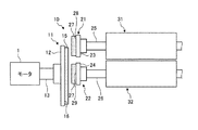
次に、上側・下側クリーニングローラ31,32に回転を伝達する動力伝達手段10について説明する。図3−1は、図1において上側・下側クリーニングローラ31,32及び動力伝達手段10を正面から見た図であり、図3−2は、図3−1を側方(クリーニングローラ側)から見た図である。なお、図3−1では被搬送物である基板50を省略して示している。また、図4は動力伝達手段10を概略的に示す図であり、左図は動力伝達手段10の正面図、右図は動力伝達手段10の磁気的な噛み合いを示す概念図である。
Next, the power transmission means 10 that transmits the rotation to the upper and
図3−1に示すように、動力伝達手段10は、駆動源(モータ)1によって軸心回りに回転駆動される駆動側円盤11と、回転軸25,26を介して上側・下側クリーニングローラ31,32に連結された一対の被駆動側円盤21,22とを備えている。この一対の被駆動側円盤21,22は、駆動側円盤11との間に所定の空隙を保ち、且つ、駆動側円盤11と互いに端面を対向させるように配置してある。ここで、駆動側円盤11の端面とは、駆動側円盤11の片面部分(平面部分)16を示しており、被駆動側円盤21,22の端面とは、被駆動側円盤21,22の片面部分(平面部分)28,29を示している。本実施の形態では、図3−2及び図4に示すように、1つの駆動側円盤11に対して二対の被駆動側円盤21,22(すなわち二対のクリーニングローラ31,32)を配置させてある。なお、以下の説明では、説明の便宜上、適宜、駆動側円盤11を駆動側磁気歯車11と呼び、被駆動側円盤21,22を、それぞれ上側磁気歯車21,下側磁気歯車22と呼ぶことにする。
As shown in FIG. 3A, the power transmission means 10 includes a drive-
駆動側磁気歯車11は、磁性体(例えば軟鉄材)からなる円盤形状の磁性盤12と、この磁性盤12とモータ1とを連結する回転軸13、及び、磁性盤12の端面16に永久磁石を接着剤等の適宜手段にて等間隔に着設することにより形成された磁気歯15とから構成される。一方、被駆動側である上側・下側磁気歯車21,22は、駆動側磁気歯車11と同様の構成を有しており、駆動側磁気歯車11よりも小さい直径を有する円盤形状の磁性体からなる磁性盤23,24と、この磁性盤23,24と上側・下側クリーニングローラ31,32とを連結する回転軸25,26、及び、磁性盤23,24の端面28,29に永久磁石を等間隔に着設することにより形成された磁気歯27から構成されている。
The drive-side
図4の右図に示すように、永久磁石からなる磁気歯15,27は、隣り合う磁気歯の極性がN極、S極と交互になるように配置してある。図4に示す駆動側磁気歯車11の磁気歯15の外形線は、例えば以下のようにして得られる。円盤の円周上の1点と円の中心とを曲線で結び、歯の数をnとして、前記曲線を360°/nずつ回転させて、n本曲線を引いていく。このn本の曲線の集合は、例えば図4に示すような放射状曲線(例えばインボリュート曲線)とすることができる。上側・下側磁気歯車21,22の磁気歯27も同様である。磁気歯15,27を上記形状とすることで、回転の伝達がスムーズに行われるとともに、磁気的噛み合いがより大きな面積で得られるため、磁気的な噛み合いが強くなる。なお、磁気歯15,27を構成する永久磁石としては、例えば40MGOeの高エネルギー積を有する希土類材が用いられる。
As shown in the right diagram of FIG. 4, the
図4の右図に示すように、本実施の形態では、下側磁気歯車22の中心(回転軸部分)が駆動側磁気歯車11の磁気歯15の内側にくるように配置してある(以下、この状態を「内接噛み合い」と呼ぶ)。一方、上側磁気歯車21の中心(回転軸部分)は、駆動側磁気歯車11の磁気歯15の外側にくるように配置してある(以下、この状態を「外接噛み合い」呼ぶ)。
As shown in the right diagram of FIG. 4, in the present embodiment, the center (rotary shaft portion) of the lower
上記構成を有する動力伝達手段10では、駆動側磁気歯車11の磁気歯15(永久磁石)と被駆動側磁気歯車21,22の磁気歯27(永久磁石)との磁気的な噛み合い、すなわち、対向する磁石のN極とS極との間の吸引力と、N極とN極及びS極とS極との間の反発力とによって、駆動側磁気歯車11から被駆動側磁気歯車21,22に、非接触で回転トルクが伝達される。例えば、駆動側磁気歯車11を図4の右図に示すように反時計方向に回転させると、被駆動側磁気歯車21,22との間に働く磁石の吸引力及び反発力によって、被駆動側磁気歯車21,22は、駆動側磁気歯車11の回転に従動して動く。すなわち、駆動側磁気歯車11が反時計方向に回転すると、駆動側磁気歯車11と内接噛み合いするように配置された下側磁気歯車22は、図4に示すように反時計方向に回転する一方、駆動側磁気歯車11と外接噛み合いするように配置された上側磁気歯車21は、図4に示すように時計周りに回転することになり、上側・下側磁気歯車21,22の回転方向は逆になる。
In the power transmission means 10 having the above-described configuration, the magnetic engagement between the magnetic teeth 15 (permanent magnet) of the drive-side
なお、上記動力伝達手段10では、磁気歯15,27の歯数を適宜に設定することで所望の回転比を得る。図4に示す例では、駆動側磁気歯車11の歯数は48、上側・下側磁気歯車21,22の歯数はそれぞれ16に設定してある。従って、駆動側磁気歯車11から上側・下側磁気歯車21,22に回転が伝わるときに、駆動側磁気歯車11に比べて上側・下側磁気歯車21,22の角速度が3倍に増える。
In the power transmission means 10, a desired rotation ratio is obtained by appropriately setting the number of teeth of the
上述した上側磁気歯車21に連結された上側クリーニングローラ31と、下側磁気歯車22に連結された下側クリーニングローラ32は、図3−2に示すように回転方向が逆向きとなる。これによって、被搬送物である基板50は、上側・下側クリーニングローラ31,32間に挟持されつつ、水平方向に搬送されることになる。
The
また、図5は、基板50の表面の凹凸に応じて上側クリーニングローラ31が上下動する状態を模式的に示した図であり、図6は、上側磁気歯車21が上方に移動した場合の駆動側磁気歯車11に対する位置を示したものである。図5に示すように、予め設定された上側・下側クリーニングローラ31,32の間隔よりも大きい厚みを有する凸部51によって上側クリーニングローラ31が上方に押し上げられると、これに伴って、上側クリーニングローラ31に連結された上側磁気歯車21も上方に押し上げられることになる。図6の上図に示すように、上側磁気歯車21が通常位置から上方へ移動すると、駆動側磁気歯車11との噛み合い面積は通常位置にある場合と比べて小さくなるものの、下図に示すように、駆動側磁気歯車11との間の空隙(エアギャップ)は一定に保たれる。このため、上側磁気歯車21が上方へ移動しても、上側クリーニングローラ31へ伝えられる回転トルクが極端に小さくなることはない。
FIG. 5 is a diagram schematically showing a state in which the
以上説明したように、本実施の形態の基板洗浄装置30によれば、駆動側円盤11及び被駆動側円盤21,22に着設された磁石の磁気の吸引力及び反発力を利用して、駆動側円盤11から被駆動側円盤21,22へ動力を伝達させる構成としたことで、駆動側から被駆動側へ非接触で動力を伝達させることが可能となり、従来のように、歯車の機械的噛み合いによる塵埃等が発生するといったことがなく、被搬送物である基板50を清浄な状態に保持した状態で搬送することができる。
As described above, according to the
また、本実施の形態の基板洗浄装置30によれば、駆動側円盤11と被駆動側円盤21,22のそれぞれの端面16,28,29に永久磁石(磁気歯15,27)を交互に異極配列し、互いの端面を対向させる態様で両者を配置した構成としたことで、クリーニングローラ31が基板の凸部51により押し上げられるのに伴い被駆動側円盤21が上動しても、駆動側円盤11との間の空隙は一定に保たれる。このため、駆動側円盤11から被駆動側円盤21に伝達されるトルクの大きさが極端に小さくなることはなく、クリーニングローラ間に挟持される被搬送物の凹凸に拘らず所望の回転トルクを維持でき、安定した回転トルクをローラに伝達することとが可能となる。
Further, according to the
さらに、本実施の形態の基板洗浄装置30によれば、ひとつの駆動側円盤11に対して、被駆動側円盤21,22を二対配置した構成としたので、動力伝達手段10の配置スペースを小さくして基板洗浄装置全体の小型化を図ることが可能となる。
Furthermore, according to the
なお、上記実施の形態では、上側クリーニングローラ31のみを上下に移動可能に構成したが、上側・下側クリーニングローラの両方を上下に移動可能に構成しても上記実施の形態と同様の効果が得られる。
In the above-described embodiment, only the
また、上述の実施の形態では、磁気歯15,27がそれぞれ等間隔に端面16,28,29に着設されているが、リング形態円形の磁石に同様の形状となる着磁を施すようにしてもよい。さらに各磁気歯15,27の太さは同じとしているが、磁気歯15の太さと磁気歯27の太さを変えてもよい。また、磁気歯15,27の形状は放射状となっているが、直線状等他の形状としてもよい。
In the above-described embodiment, the
以上のように、本発明に係る搬送装置は、上記実施の形態で示した基板洗浄装置をはじめ、一対のローラ間に挟持される被搬送物の凹凸に応じてローラを上下動させながらローラを回転させて被搬送物を搬送する搬送装置に有効に用いることができる。 As described above, the transport device according to the present invention includes the substrate cleaning device described in the above embodiment and the rollers while moving the rollers up and down according to the unevenness of the transported object sandwiched between the pair of rollers. The present invention can be effectively used for a conveying device that rotates and conveys an object to be conveyed.
1 モータ(駆動源)
10 動力伝達手段
11 駆動側磁気歯車(駆動側円盤)
12 磁性盤
13 回転軸
15 磁気歯(永久磁石)
16 (駆動側磁気歯車の)端面
21 上側磁気歯車(被駆動側円盤)
22 下側磁気歯車(被駆動側円盤)
23,24 磁性盤
25,26 回転軸
27 磁気歯(永久磁石)
28 (上側磁気歯車の)端面
29 (下側磁気歯車の)端面
30 基板洗浄装置
31 上側クリーニングローラ(ローラ)
32 下側クリーニングローラ(ローラ)
50 基板(被搬送物)
1 Motor (drive source)
10 Power transmission means 11 Drive side magnetic gear (drive side disk)
12
16 End face (of driving side magnetic gear) 21 Upper side magnetic gear (driven side disk)
22 Lower magnetic gear (driven disk)
23, 24
28 End surface (of the upper magnetic gear) 29 End surface (of the lower magnetic gear) 30
32 Lower cleaning roller (roller)
50 Substrate (conveyed object)
Claims (3)
前記一対のローラ間に被搬送物を挟持させつつ前記一対のローラを回転させることにより被搬送物を搬送する搬送装置において、
前記動力伝達手段は、
駆動源によって軸心回りに回転駆動される駆動側円盤と、
前記一対のローラにそれぞれ連結され、前記駆動側円盤との間に所定の空隙を保ち、且つそれぞれが前記駆動側円盤と互いに端面を対向させるように配置された一対の被駆動側円盤とを備え、
前記駆動側円盤及び前記一対の被駆動側円盤のそれぞれの端面に永久磁石をN極、S極と交互に放射状に異極配列して磁気歯を構成し、一方の被駆動側円盤の中心を前記駆動側円盤における磁気歯の内側に配置させるとともに、他方の被駆動側円盤の中心を前記駆動側円盤における磁気歯の外側に配置させた状態でそれぞれの磁気歯を対向させ、これら対向する磁気歯の磁力により、前記駆動側円盤から前記一対の被駆動側円盤へ動力を伝達させることを特徴とする搬送装置。 Comprising power transmission means for transmitting rotation to the pair of rollers;
In the transport device that transports the transported object by rotating the pair of rollers while sandwiching the transported object between the pair of rollers,
The power transmission means is
A drive-side disk that is rotationally driven around the axis by a drive source;
A pair of driven-side disks that are respectively connected to the pair of rollers, maintain a predetermined gap with the driving-side disk, and are arranged so that the end surfaces of the driving-side disk face each other. ,
Permanent magnets are arranged radially and alternately with N poles and S poles on the respective end faces of the drive side disk and the pair of driven side disks to form magnetic teeth, and the center of one driven side disk is formed. The magnetic teeth are arranged inside the magnetic teeth in the driving side disk, and the magnetic teeth are opposed to each other in a state where the center of the other driven side disk is arranged outside the magnetic teeth in the driving side disk. A conveying apparatus that transmits power from the driving disk to the pair of driven disks by a magnetic force of teeth .
前記下側のローラに連結した被駆動側円盤の中心を前記駆動側円盤における磁気歯の内側に配置させるとともに、前記上側のローラに連結した被駆動側円盤の中心を前記駆動側円盤における磁気歯の外側に配置させたことを特徴とする請求項1に記載の搬送装置。 The pair of rollers are arranged vertically on the side wall plate, and the lower roller is arranged so as to be rotatable about its own axis with respect to the side wall plate and restricted in movement in a direction perpendicular to the axis. On the other hand, the upper roller is arranged so as to be rotatable about its own axis with respect to the side wall plate and to be movable in the vertical direction.
The center of the driven disk connected to the lower roller is arranged inside the magnetic tooth in the driving disk, and the center of the driven disk connected to the upper roller is arranged to be the magnetic tooth in the driving disk. The conveying apparatus according to claim 1, wherein the conveying apparatus is arranged outside the first side.
Priority Applications (4)
| Application Number | Priority Date | Filing Date | Title |
|---|---|---|---|
| JP2007135957A JP4406652B2 (en) | 2007-05-22 | 2007-05-22 | Transport device |
| TW096119075A TWI325036B (en) | 2007-05-22 | 2007-05-29 | Transporting apparatus |
| KR1020070053149A KR20080102925A (en) | 2007-05-22 | 2007-05-31 | Conveying device |
| CN2007101269941A CN101312322B (en) | 2007-05-22 | 2007-07-04 | Conveying appliance |
Applications Claiming Priority (1)
| Application Number | Priority Date | Filing Date | Title |
|---|---|---|---|
| JP2007135957A JP4406652B2 (en) | 2007-05-22 | 2007-05-22 | Transport device |
Publications (2)
| Publication Number | Publication Date |
|---|---|
| JP2008290812A JP2008290812A (en) | 2008-12-04 |
| JP4406652B2 true JP4406652B2 (en) | 2010-02-03 |
Family
ID=40100783
Family Applications (1)
| Application Number | Title | Priority Date | Filing Date |
|---|---|---|---|
| JP2007135957A Expired - Fee Related JP4406652B2 (en) | 2007-05-22 | 2007-05-22 | Transport device |
Country Status (4)
| Country | Link |
|---|---|
| JP (1) | JP4406652B2 (en) |
| KR (1) | KR20080102925A (en) |
| CN (1) | CN101312322B (en) |
| TW (1) | TWI325036B (en) |
Families Citing this family (9)
| Publication number | Priority date | Publication date | Assignee | Title |
|---|---|---|---|---|
| KR100987763B1 (en) * | 2008-07-01 | 2010-10-13 | 김학사 | Substrate processing equipment |
| CN102529424A (en) * | 2010-12-25 | 2012-07-04 | 富葵精密组件(深圳)有限公司 | Automatic spray printing machine |
| JP2013071824A (en) * | 2011-09-28 | 2013-04-22 | Meinan Mach Works Inc | Operating method and operating device of press roll in high-speed conveying equipment of sheet body |
| JP5781416B2 (en) * | 2011-10-17 | 2015-09-24 | 株式会社ヒラノテクシード | Web stabilizer |
| TWI672258B (en) * | 2012-05-18 | 2019-09-21 | 日商尼康股份有限公司 | Exposure apparatus |
| EP3585713B1 (en) | 2017-02-24 | 2023-07-12 | ABB Schweiz AG | Auxiliary conveyor and corresponding conveying system |
| CN108506456B (en) * | 2018-06-22 | 2024-08-02 | 红塔辽宁烟草有限责任公司沈阳卷烟厂 | Magnetic force meshing gear device of steering part of cigarette filter stick receiver |
| CN108866834B (en) * | 2018-08-01 | 2020-09-22 | 东莞广上运动用品有限公司 | Sewing machine for smooth sewing material flattened by magnetic force |
| EP3955063B1 (en) * | 2020-08-12 | 2024-07-03 | The Swatch Group Research and Development Ltd | Watch mechanism provided with a magnetic gear |
Family Cites Families (3)
| Publication number | Priority date | Publication date | Assignee | Title |
|---|---|---|---|---|
| JP4326472B2 (en) * | 2002-10-11 | 2009-09-09 | ユニテク株式会社 | Substrate cleaning device |
| JP3942101B2 (en) * | 2003-09-19 | 2007-07-11 | 株式会社松栄工機 | Magnetic gear |
| DE102004023909A1 (en) * | 2004-05-13 | 2005-12-08 | Atotech Deutschland Gmbh | transport device |
-
2007
- 2007-05-22 JP JP2007135957A patent/JP4406652B2/en not_active Expired - Fee Related
- 2007-05-29 TW TW096119075A patent/TWI325036B/en not_active IP Right Cessation
- 2007-05-31 KR KR1020070053149A patent/KR20080102925A/en not_active Application Discontinuation
- 2007-07-04 CN CN2007101269941A patent/CN101312322B/en not_active Expired - Fee Related
Also Published As
| Publication number | Publication date |
|---|---|
| TW200846569A (en) | 2008-12-01 |
| KR20080102925A (en) | 2008-11-26 |
| TWI325036B (en) | 2010-05-21 |
| CN101312322A (en) | 2008-11-26 |
| JP2008290812A (en) | 2008-12-04 |
| CN101312322B (en) | 2011-03-16 |
Similar Documents
| Publication | Publication Date | Title |
|---|---|---|
| JP4406652B2 (en) | Transport device | |
| JP3612978B2 (en) | Conveying device, conveying method, and manufacturing method of liquid crystal display device | |
| JP4541383B2 (en) | Transport device | |
| JP4438823B2 (en) | Dust remover | |
| WO2012081168A1 (en) | Sputtering apparatus | |
| JP6647492B2 (en) | Non-contact drive transmission | |
| JP2000142935A (en) | Transfer method and transfer device | |
| JP7463222B2 (en) | Magnetic Coupling Device | |
| KR20120110789A (en) | Backlash mesurement apparatus | |
| JP2005253292A (en) | High torque transmission non-contact gear | |
| KR20070090503A (en) | Magnetic gears and magnetic conveyors using them | |
| JPH1155932A (en) | Noncontact type power transmission mechanism | |
| KR20120004136A (en) | Non-contact Rotating System Using Magnet in Dissimilar Region | |
| JP2010241557A (en) | Roller conveyor device | |
| JP2011011857A (en) | Roller conveyor device | |
| JP2009137689A (en) | Roller conveyor device | |
| US7622839B2 (en) | Magnetic belt and roller system | |
| JP2010222125A (en) | Roller conveyor device | |
| JP2009137688A (en) | Roller conveyor device | |
| JP2008253062A (en) | Driving force transmission device and substrate processing device | |
| KR20070045537A (en) | System for transfering substrates | |
| JPH1163164A (en) | Motive power transmission device and roller conveyor | |
| JP2005350171A (en) | Roller conveyor | |
| JP4605583B2 (en) | Roller conveyor | |
| KR100870147B1 (en) | Substrate processing equipment |
Legal Events
| Date | Code | Title | Description |
|---|---|---|---|
| A131 | Notification of reasons for refusal |
Free format text: JAPANESE INTERMEDIATE CODE: A131 Effective date: 20090210 |
|
| A521 | Written amendment |
Free format text: JAPANESE INTERMEDIATE CODE: A523 Effective date: 20090403 |
|
| TRDD | Decision of grant or rejection written | ||
| A01 | Written decision to grant a patent or to grant a registration (utility model) |
Free format text: JAPANESE INTERMEDIATE CODE: A01 Effective date: 20091013 |
|
| A01 | Written decision to grant a patent or to grant a registration (utility model) |
Free format text: JAPANESE INTERMEDIATE CODE: A01 |
|
| A61 | First payment of annual fees (during grant procedure) |
Free format text: JAPANESE INTERMEDIATE CODE: A61 Effective date: 20091109 |
|
| FPAY | Renewal fee payment (event date is renewal date of database) |
Free format text: PAYMENT UNTIL: 20121113 Year of fee payment: 3 |
|
| R150 | Certificate of patent or registration of utility model |
Ref document number: 4406652 Country of ref document: JP Free format text: JAPANESE INTERMEDIATE CODE: R150 Free format text: JAPANESE INTERMEDIATE CODE: R150 |
|
| FPAY | Renewal fee payment (event date is renewal date of database) |
Free format text: PAYMENT UNTIL: 20121113 Year of fee payment: 3 |
|
| FPAY | Renewal fee payment (event date is renewal date of database) |
Free format text: PAYMENT UNTIL: 20121113 Year of fee payment: 3 |
|
| S533 | Written request for registration of change of name |
Free format text: JAPANESE INTERMEDIATE CODE: R313533 |
|
| FPAY | Renewal fee payment (event date is renewal date of database) |
Free format text: PAYMENT UNTIL: 20121113 Year of fee payment: 3 |
|
| R350 | Written notification of registration of transfer |
Free format text: JAPANESE INTERMEDIATE CODE: R350 |
|
| FPAY | Renewal fee payment (event date is renewal date of database) |
Free format text: PAYMENT UNTIL: 20121113 Year of fee payment: 3 |
|
| FPAY | Renewal fee payment (event date is renewal date of database) |
Free format text: PAYMENT UNTIL: 20121113 Year of fee payment: 3 |
|
| FPAY | Renewal fee payment (event date is renewal date of database) |
Free format text: PAYMENT UNTIL: 20121113 Year of fee payment: 3 |
|
| FPAY | Renewal fee payment (event date is renewal date of database) |
Free format text: PAYMENT UNTIL: 20191113 Year of fee payment: 10 |
|
| R250 | Receipt of annual fees |
Free format text: JAPANESE INTERMEDIATE CODE: R250 |
|
| LAPS | Cancellation because of no payment of annual fees |