JP4403010B2 - Signal separation device - Google Patents
Signal separation device Download PDFInfo
- Publication number
- JP4403010B2 JP4403010B2 JP2004136663A JP2004136663A JP4403010B2 JP 4403010 B2 JP4403010 B2 JP 4403010B2 JP 2004136663 A JP2004136663 A JP 2004136663A JP 2004136663 A JP2004136663 A JP 2004136663A JP 4403010 B2 JP4403010 B2 JP 4403010B2
- Authority
- JP
- Japan
- Prior art keywords
- signal
- sampling
- received
- separation device
- signals
- Prior art date
- Legal status (The legal status is an assumption and is not a legal conclusion. Google has not performed a legal analysis and makes no representation as to the accuracy of the status listed.)
- Expired - Fee Related
Links
Images


Classifications
-
- H—ELECTRICITY
- H04—ELECTRIC COMMUNICATION TECHNIQUE
- H04L—TRANSMISSION OF DIGITAL INFORMATION, e.g. TELEGRAPHIC COMMUNICATION
- H04L25/00—Baseband systems
- H04L25/02—Details ; arrangements for supplying electrical power along data transmission lines
- H04L25/03—Shaping networks in transmitter or receiver, e.g. adaptive shaping networks
- H04L25/03006—Arrangements for removing intersymbol interference
- H04L25/03178—Arrangements involving sequence estimation techniques
- H04L25/03248—Arrangements for operating in conjunction with other apparatus
- H04L25/0328—Arrangements for operating in conjunction with other apparatus with interference cancellation circuitry
-
- H—ELECTRICITY
- H04—ELECTRIC COMMUNICATION TECHNIQUE
- H04L—TRANSMISSION OF DIGITAL INFORMATION, e.g. TELEGRAPHIC COMMUNICATION
- H04L25/00—Baseband systems
- H04L25/02—Details ; arrangements for supplying electrical power along data transmission lines
- H04L25/03—Shaping networks in transmitter or receiver, e.g. adaptive shaping networks
- H04L25/03006—Arrangements for removing intersymbol interference
- H04L25/03178—Arrangements involving sequence estimation techniques
- H04L25/03248—Arrangements for operating in conjunction with other apparatus
- H04L25/03254—Operation with other circuitry for removing intersymbol interference
-
- H—ELECTRICITY
- H04—ELECTRIC COMMUNICATION TECHNIQUE
- H04L—TRANSMISSION OF DIGITAL INFORMATION, e.g. TELEGRAPHIC COMMUNICATION
- H04L25/00—Baseband systems
- H04L25/02—Details ; arrangements for supplying electrical power along data transmission lines
- H04L25/03—Shaping networks in transmitter or receiver, e.g. adaptive shaping networks
- H04L25/03006—Arrangements for removing intersymbol interference
- H04L25/03178—Arrangements involving sequence estimation techniques
- H04L25/03248—Arrangements for operating in conjunction with other apparatus
- H04L25/03292—Arrangements for operating in conjunction with other apparatus with channel estimation circuitry
-
- H—ELECTRICITY
- H04—ELECTRIC COMMUNICATION TECHNIQUE
- H04B—TRANSMISSION
- H04B2201/00—Indexing scheme relating to details of transmission systems not covered by a single group of H04B3/00 - H04B13/00
- H04B2201/69—Orthogonal indexing scheme relating to spread spectrum techniques in general
- H04B2201/707—Orthogonal indexing scheme relating to spread spectrum techniques in general relating to direct sequence modulation
- H04B2201/70703—Orthogonal indexing scheme relating to spread spectrum techniques in general relating to direct sequence modulation using multiple or variable rates
-
- H—ELECTRICITY
- H04—ELECTRIC COMMUNICATION TECHNIQUE
- H04L—TRANSMISSION OF DIGITAL INFORMATION, e.g. TELEGRAPHIC COMMUNICATION
- H04L25/00—Baseband systems
- H04L25/02—Details ; arrangements for supplying electrical power along data transmission lines
- H04L25/03—Shaping networks in transmitter or receiver, e.g. adaptive shaping networks
- H04L25/03006—Arrangements for removing intersymbol interference
- H04L2025/0335—Arrangements for removing intersymbol interference characterised by the type of transmission
- H04L2025/03375—Passband transmission
-
- H—ELECTRICITY
- H04—ELECTRIC COMMUNICATION TECHNIQUE
- H04L—TRANSMISSION OF DIGITAL INFORMATION, e.g. TELEGRAPHIC COMMUNICATION
- H04L25/00—Baseband systems
- H04L25/02—Details ; arrangements for supplying electrical power along data transmission lines
- H04L25/03—Shaping networks in transmitter or receiver, e.g. adaptive shaping networks
- H04L25/03006—Arrangements for removing intersymbol interference
- H04L2025/03433—Arrangements for removing intersymbol interference characterised by equaliser structure
- H04L2025/03439—Fixed structures
- H04L2025/03445—Time domain
- H04L2025/03471—Tapped delay lines
- H04L2025/03484—Tapped delay lines time-recursive
- H04L2025/0349—Tapped delay lines time-recursive as a feedback filter
Landscapes
- Engineering & Computer Science (AREA)
- Power Engineering (AREA)
- Computer Networks & Wireless Communication (AREA)
- Signal Processing (AREA)
- Cable Transmission Systems, Equalization Of Radio And Reduction Of Echo (AREA)
- Noise Elimination (AREA)
Description
本発明は、移動無線及び固定無線の受信機に用いられる信号分離装置に関する。 The present invention relates to a signal separation device used for mobile radio and fixed radio receivers.
無線通信システムにおいては、限られた周波数資源を効率的に使用するために、可能な限り多くの信号が同一周波数を用いるのが望ましい。例えば、干渉キャンセラは、このような背景から研究・開発が進めらており、システムの容量を増大させることのできる技術として注目されている。 In a wireless communication system, it is desirable that as many signals as possible use the same frequency in order to efficiently use limited frequency resources. For example, the interference canceller has been researched and developed from such a background, and has attracted attention as a technology capable of increasing the capacity of the system.
図18は、従来の干渉キャンセラの一例を示す構成図である。同図に示す干渉キャンセラは無線通信システムの受信機に備えられ、受信信号のレプリカを生成して希望信号とその他の信号(干渉信号)を分離して取り出すレプリカ生成型干渉キャンセラと呼ばれている。 FIG. 18 is a configuration diagram illustrating an example of a conventional interference canceller. The interference canceller shown in the figure is provided in a receiver of a wireless communication system, and is called a replica generation type interference canceller that generates a replica of a received signal and separates and extracts a desired signal and other signals (interference signals). .
以下、図18を参照して、レプリカ生成型干渉キャンセラの動作を説明する。 The operation of the replica generation type interference canceller will be described below with reference to FIG.
このレプリカ生成型干渉キャンセラ300は、伝搬路推定部318において希望信号及び干渉信号の伝搬路のレベル変動や位相回転量を推定し、係数可変形フィルタa314、及び係数可変形フィルタb315において上記推定したレベル変動及び位相回転量を、希望信号及び干渉信号の取り得る全てのシンボル系列候補に乗算することにより、全てのシンボル系列候補に対して希望信号レプリカと干渉信号レプリカを生成し、加算器316でそれらの和をとって受信信号レプリカを生成する。そして、実際の受信信号と最も近い受信信号のレプリカを与える希望信号及び干渉信号のシンボル系列候補を最尤系列推定部320で判定し、希望信号のシンボル系列候補を受信信号の判定結果として出力することにより、実効的に干渉を除去する。
In the replica generation
このように受信信号から適応的に干渉信号を除去することにより、異なる複数の信号が同一時刻に同一周波数にて使用することが可能となり、周波数利用効率を向上させることが可能となる。 Thus, by adaptively removing the interference signal from the received signal, a plurality of different signals can be used at the same time at the same frequency, and the frequency utilization efficiency can be improved.
また、複数種類の伝送レートを含むマルチレート伝送システムにおける干渉キャンセラが提案されている。この技術によれば、伝送レートの高い高速チャネルと、伝送レートの低い低速チャネルとを混在して無線通信を行うDS−CDMA方式において、アレーアンテナにより受信する構成とし、かつ高速チャネルによる干渉レプリカを生成するアレーアンテナ干渉レプリカ生成ユニットを設けて、受信信号に対する高速チャネルによる干渉を除去することで、高速チャネルによる干渉を除去して、低速チャネルの伝送品質の向上を図る旨が記載されている(例えば、特許文献1参照)。
しかしながら、上述した従来のレプリカ生成型干渉キャンセラは、希望信号及び干渉信号のレプリカを生成することにより、実効的に干渉を除去することが可能であるが、希望信号と干渉信号の信号帯域幅が等しい場合を想定しているため、広帯域を要求する希望信号と、狭帯域を要求する信号を対象とする干渉信号が合成されて受信される場合、十分な干渉抑圧効果を得ることができない。このため、レプリカ生成型干渉キャンセラによる周波数利用効率改善効果を得るためには、同一周波数上で広帯域信号に狭帯域信号を重ねて利用することができないという問題が発生する。 However, the above-described conventional replica generation type interference canceller can effectively remove interference by generating a desired signal and a replica of the interference signal, but the signal bandwidth of the desired signal and the interference signal is small. Since equal cases are assumed, when a desired signal requiring a wide band and an interference signal targeting a signal requiring a narrow band are combined and received, a sufficient interference suppression effect cannot be obtained. For this reason, in order to obtain the effect of improving the frequency utilization efficiency by the replica generation type interference canceller, there arises a problem that the narrowband signal cannot be superimposed on the wideband signal on the same frequency.
本発明は、上記のような問題点に鑑みてなされたもので、その課題とするところは、信号帯域幅が異なる干渉信号に対して干渉除去を可能とし、同一周波数帯域に広帯域信号と狭帯域信号を共存させることのできる信号分離装置を提供することである。 The present invention has been made in view of the above-described problems, and the object of the present invention is to enable interference removal with respect to interference signals having different signal bandwidths, so that a wideband signal and a narrowband are in the same frequency band. It is an object of the present invention to provide a signal separation device capable of coexisting signals.
上記課題を解決するため、本発明は、請求項1に記載されるように、受信信号のレプリカを生成して受信される複数の信号を分離する信号分離装置であって、前記複数の信号からなる受信信号の標本化を行う標本化手段と、前記標本化のタイミングを制御する標本化制御手段と、前記標本化手段における標本化回数を計測し、その計測された標本化回数を所定時間あたりの標本化回数で除算したときの剰余を受信信号のインデックス信号として出力するインデックス出力手段と、前記受信される複数の信号のレベル変動量及び位相回転量を推定する伝搬路推定手段と、受信される複数の信号について、信号空間上でインデックス出力手段が指定するインデックスに対応する信号点の候補を出力する信号発生手段と、前記伝搬路推定手段により推定されるレベル変動量及び位相回転量と、前記信号発生手段から出力される信号点候補とを用いて作成した前記受信信号のレプリカを出力する係数可変型フィルタと、前記係数可変型フィルタから出力される前記受信信号のレプリカを前記標本化後の受信信号から減算し、前記伝搬路推定手段及び自乗器へ入力する減算器と、前記減算器からの減算結果の自乗を尤度信号として、信号の状態遷移を考慮した状態推定手段から最尤系列推定により受信された複数の信号の信号系列を推定し、その推定された信号系列に基づいて送信された信号を復調し、インデックス出力手段からのインデックス信号に基づいて決定されるタイミングで出力する最尤系列推定手段と、を備え、前記インデックス出力手段が出力するインデックスに基づいて標本化した信号を分類し、その分類ごとに信号点候補を生成して受信される複数の信号を分離することを特徴としている。
In order to solve the above problems, the present invention provides a signal separation device for generating a replica of a received signal and separating a plurality of received signals, as described in
また、本発明の請求項2によれば、受信信号のレプリカを生成して受信される複数の信号を分離する信号分離装置であって、前記複数の信号からなる受信信号の標本化を行う標本化手段と、前記標本化のタイミングを制御する標本化制御手段と、前記標本化手段における標本化回数を計測し、その計測された標本化回数を所定時間あたりの標本化回数で除算したときの剰余を受信信号のインデックス信号として出力するインデックス出力手段と、前記インデックス出力手段により指定されるインデックスごとに受信される複数の信号のレベル変動量及び位相回転量を推定する伝搬路推定手段と、受信される複数の信号について、信号空間上で信号点の候補を出力する信号発生手段と、前記伝搬路推定手段により推定されるレベル変動量及び位相回転量と、前記信号発生手段から出力される信号点候補とを用いて作成した前記受信信号のレプリカを出力する係数可変型フィルタと、前記係数可変型フィルタから出力される前記受信信号のレプリカを前記標本化後の受信信号から減算し、前記伝搬路推定手段及び自乗器へ入力する減算器と、前記減算器からの減算結果の自乗を尤度信号として、信号の状態遷移を考慮した状態推定手段から最尤系列推定により受信された複数の信号の信号系列を推定し、その推定された信号系列に基づいて送信された信号を復調し、インデックス出力手段からのインデックス信号に基づいて決定されるタイミングで出力する最尤系列推定手段と、を備え、前記インデックス出力手段が出力するインデックスに基づいて標本化した信号を分類し、その分類ごとに受信信号のレベル変動及び位相回転量を推定して受信される複数の信号を分離することを特徴としている。 According to a second aspect of the present invention, there is provided a signal separating device for generating a replica of a received signal and separating a plurality of received signals, and for sampling a received signal composed of the plurality of signals. Sampling means, sampling control means for controlling the sampling timing, and measuring the number of sampling times in the sampling means, and dividing the measured number of sampling times by the number of sampling times per predetermined time Index output means for outputting the remainder as an index signal of the received signal, propagation path estimation means for estimating the level fluctuation amount and phase rotation amount of a plurality of signals received for each index specified by the index output means, and reception Signal generating means for outputting signal point candidates on the signal space, and the level fluctuation amount and level estimated by the propagation path estimating means A coefficient variable filter that outputs a replica of the received signal created using a rotation amount and a signal point candidate output from the signal generating means; and a replica of the received signal output from the coefficient variable filter Subtractor subtracted from the sampled received signal and input to the propagation path estimation means and squarer, and state estimation in consideration of signal state transition using the square of the subtraction result from the subtractor as a likelihood signal A signal sequence of a plurality of signals received by means of maximum likelihood sequence estimation is estimated from the means, a signal transmitted based on the estimated signal sequence is demodulated, and determined based on an index signal from the index output means Maximum likelihood sequence estimation means for outputting at timing, and classifying the sampled signal based on the index output by the index output means, and the classification It is characterized by separating a plurality of signals received by estimating the level fluctuation and phase rotation amount of a received signal and.
また、本発明の請求項3によれば、前記信号分離装置であって、前記複数の受信信号のうち、いずれかの信号を被選択信号として選択し、選択した被選択信号の前記伝搬路推定手段における伝搬路推定値を所定時間分保持する記憶手段と、前記最尤系列推定手段における被選択信号の判定結果に対応する信号点を出力する信号発生手段と、前記記憶手段に保持されている伝搬路推定値を参照してフィルタ係数を定め、前記信号発生手段から出力される信号点を用いて被選択信号のレプリカ信号を出力する係数可変型フィルタと、受信信号を所定時間遅延させる遅延手段と、前記遅延手段からの出力と被選択信号のレプリカを減算する減算器と、被選択信号を選択する信号選択手段と、を備え、前記最尤系列推定手段における被選択信号の判定結果から得られる信号点及び前記伝搬路推定手段において推定され、前記記憶手段に保持されている被選択信号のレベル変動量及び位相回転量を用いて、係数可変型フィルタにおいて被選択信号のレプリカを生成し、受信信号から被選択信号のレプリカを減算することにより、受信信号から被選択信号を取り除いた信号を抽出することを特徴としている。
According to
また、本発明の請求項4によれば、前記信号分離装置であって、前記信号選択手段は、複数の受信信号のうち、受信品質が高い信号を被選択信号として選択することを特徴としている。 According to a fourth aspect of the present invention, in the signal separation device, the signal selection unit selects a signal having a high reception quality from among a plurality of reception signals as a selected signal. .
また、本発明の請求項5によれば、前記信号分離装置であって、前記信号選択手段は、複数の受信信号のうち、シンボルレートの低い信号を被選択信号として選択することを特徴としている。 According to a fifth aspect of the present invention, in the signal separation device, the signal selection unit selects a signal having a low symbol rate from among a plurality of received signals as a selected signal. .
また、本発明の請求項6によれば、前記信号分離装置であって、前記信号発生手段は、受信信号の全てのシンボル系列候補に対して、雑音又はフェージングの影響を受けていない信号波形を出力し、その信号波形を、前記標本化制御手段において指定される標本化タイミングで標本化を行うことにより、信号空間上で信号点候補を出力することを特徴としている。
According to
また、本発明の請求項7によれば、前記信号分離装置であって、前記インデックス出力手段により指定されるインデックスごとに、自乗器から出力される信号に乗算する重み係数を定める重み係数制御手段を備えることを特徴としている。
According to
また、本発明の請求項8によれば、前記信号分離装置であって、前記標本化制御手段は、複数の受信信号それぞれのシンボルレートに合わせて受信信号を標本化し、それを時系列で並べて出力するように標本化手段を制御することを特徴としている。 Further, according to claim 8 of the present invention, in the signal separation device, the sampling control unit samples the received signal according to the symbol rate of each of the plurality of received signals, and arranges them in time series. It is characterized by controlling the sampling means to output.
また、本発明の請求項9によれば、前記信号分離装置であって、前記標本化制御手段は、複数の受信信号のシンボルレートの公倍数となるレートに応じて受信信号を標本化するように標本化手段を制御することを特徴としている。 According to claim 9 of the present invention, in the signal separation device, the sampling control means samples the received signal according to a rate that is a common multiple of a symbol rate of the plurality of received signals. It is characterized by controlling the sampling means.
また、本発明の請求項10によれば、前記信号分離装置であって、前記係数可変型フィルタは、遅延波の時間的広がりをもって到来する信号に対応する複数の係数入力タップを有し、遅延波を含む受信信号のレプリカを出力することを特徴としている。 According to a tenth aspect of the present invention, in the signal separation device, the coefficient variable filter includes a plurality of coefficient input taps corresponding to a signal that arrives with a time spread of a delayed wave, and a delay. It is characterized by outputting a replica of a received signal including a wave.
また、本発明の請求項10によれば、前記信号分離装置であって、前記信号発生手段は、時間的に前後する少なくとも1つのシンボルを考慮して現在の信号点候補を出力することを特徴としている。 According to a tenth aspect of the present invention, in the signal separation device, the signal generation means outputs a current signal point candidate in consideration of at least one symbol that changes in time. It is said.
また、本発明の請求項11によれば、前記信号分離装置であって、前記最尤系列推定手段は、信号の状態として、前記時間的に前後する少なくとも1つのシンボルを考慮し、信号の状態遷移に基づいて、送信された信号系列を推定することを特徴としている。 According to an eleventh aspect of the present invention, in the signal separation device, the maximum likelihood sequence estimation means considers at least one symbol that moves around in time as the signal state, and the signal state It is characterized in that the transmitted signal sequence is estimated based on the transition.
本願発明によれば、符号間干渉の条件により、標本化後の信号を分類し、その分類ごとに信号分離動作を行うことにより、異なるシンボルレートの信号が同一周波数上に存在する場合について、それぞれの信号を分離して取り出すことが可能となる。 According to the present invention, by classifying a sampled signal according to the condition of intersymbol interference and performing a signal separation operation for each classification, when signals of different symbol rates exist on the same frequency, Can be separated and extracted.
以下、以下本発明の実施形態を図面と共に説明する。 Hereinafter, embodiments of the present invention will be described with reference to the drawings.
(第1の実施形態)
まず、図1を参照しながら、第1の実施形態に係る信号分離装置1の構成を説明する。図1は、第1の実施形態に係る信号分離装置1の構成を示すブロック図である。この信号分離装置1は、送信信号のシンボルレートが異なる複数の送信側無線局と複数の受信側無線局が存在し、同一周波数帯を用いて通信を行う無線通信システムにおいて用いられ、受信側の固定無線局または移動無線局に備えられる。
(First embodiment)
First, the configuration of the
図1において、上記信号分離装置1は、標本化部11と、標本化制御部12と、インデックス出力部13と、信号発生部a14と、信号発生部b15と、係数可変形フィルタa16と、係数可変形フィルタb17と、加算器18と、減算器19と、伝搬路推定部20と、自乗器21と、最尤系列推定部22とから構成される。
In FIG. 1, the
本実施形態では、入力信号は、ベースバンド信号とし、ロールオフフィルタ等により帯域制限が行われた後の信号とする。また、説明を平易にするために、受信信号が2波(信号1、信号2)の場合を想定し、以下説明を進める。
In this embodiment, the input signal is a baseband signal and is a signal after band limitation is performed by a roll-off filter or the like. In order to simplify the description, the following description will be given assuming that the received signal is two waves (
図1において、まず、信号分離装置1に入力された信号は、標本化部11に入力され、標本化制御部12から出力される標本化タイミングにしたがって標本化されて離散時間信号に変換される。ここで、標本化制御部12は、受信信号のシンボルレート(信号1のシンボルレートfs1、信号2のシンボルレートfs2)に応じた標本化タイミングをタイミング情報として標本化部11に出力する。
In FIG. 1, first, a signal input to the
次に、図1に示す標本化部11における標本化方法について図2を用いて説明する。図2は、図1に示す標本化部11の構成例を示す図である。
Next, a sampling method in the
同図において、上記標本化部11は、サンプリング処理部a31、サンプリング処理部b32、スイッチ制御部33、スイッチ34から構成される。
In the figure, the
標本化部11に入力された入力信号は、サンプリング処理部a31、サンプリング処理部b32にパラレルに入力される。これらの入力信号は、標本化制御部12から出力されるシンボルレートに応じた標本化タイミングで標本化された後、スイッチ部34に出力される。スイッチ制御部33は、標本化制御部12から出力されるシンボルレートに応じた標本化タイミングの情報に基づいてスイッチを切り替え、スイッチ34からサンプル値が時間順に並べられて出力されるように制御する。
The input signal input to the
上記のような操作を経ることで、入力信号が不等間隔で標本化されて次段に出力される。 Through the above operation, the input signal is sampled at unequal intervals and output to the next stage.
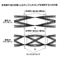
図3は、標本化部11で不等間隔サンプリングされた場合のアイパターン及びサンプルタイミングとインデックスの対応例を示す図である。同図上段は、信号1のアイパターンを、下段は信号2のアイパターンを示している。本例では、簡単のため、各信号のアイパターンが最も開いている点、すなわち、アイの中央のタイミング(アイ開口タイミング)をサンプリングタイミングとして理想的に標本化できているとし、シンボルレート比は(信号1):(信号2)=2:3としている。
FIG. 3 is a diagram illustrating an example of correspondence between eye patterns, sample timings, and indexes when sampling is performed by the
なお、同図に示されるサンプリングタイミングとインデックスの対応関係については、後述する。 The correspondence between the sampling timing and the index shown in FIG.
上記したように、本実施形態における標本化制御部12では、複数の受信信号それぞれのシンボルレートに合わせて受信信号を標本化し、それを時系列で並べて出力するように標本化部を制御する。これにより、受信信号点が信号空間上で分散し、複数の信号を分離しやすくなるタイミングで標本化を行うことが可能となる。
As described above, the
また、本実施形態では、上記した不等間隔サンプリング法の他に、図4に示す処理手順にしたがって標本化周波数を定め、標本化する方法もある。以下、この方法について説明する。 Further, in the present embodiment, in addition to the unequal interval sampling method described above, there is also a method of sampling by determining the sampling frequency according to the processing procedure shown in FIG. Hereinafter, this method will be described.
図4に示す標本化方法では、複数の信号のシンボルレートの最小公倍数が求められ、その求められたシンボルレートの公倍数の整数倍のレートで標本化が行われるように標本化周波数を定め、等間隔でサンプリングされる。ここでは、この方法を、等間隔サンプリング方法と呼ぶ。 In the sampling method shown in FIG. 4, the least common multiple of symbol rates of a plurality of signals is obtained, and the sampling frequency is determined so that sampling is performed at a rate that is an integral multiple of the common multiple of the obtained symbol rates. Sampled at intervals. Here, this method is called an equidistant sampling method.
続いて、図4のフローチャートを参照して等間隔サンプリング法による標本化周波数の決定手順を説明する。 Next, the procedure for determining the sampling frequency by the equidistant sampling method will be described with reference to the flowchart of FIG.
図4において、ステップS1において、複数の信号のシンボルレート(fs1,fs2,...)の最小公倍数fLCM(LCM: Least Common Multiple)が、まず計算される。次に、ステップS2において、上記最小公倍数fLCMと複数の信号のシンボルレートとが比較判定(次式参照)される。 In FIG. 4, in step S1, a least common multiple f LCM (LCM: Least Common Multiple) of symbol rates (f s1 , f s2 ,...) Of a plurality of signals is first calculated. Next, in step S2, the least common multiple f LCM is compared with a symbol rate of a plurality of signals (see the following equation).
fLCM≠fsk for∀k?
ここで、fskにおけるkは1以上の整数を表し、
∀は、複数の信号のすべてのシンボルレートを表す。
f LCM ≠ f sk for ∀ k?
Here, k in fsk represents an integer of 1 or more,
∀ represents all symbol rates of a plurality of signals.
すなわち、上記比較判定(ステップS2)では、最小公倍数fLCMと複数の信号のシンボルレート(fs1,fs2,...)とが比較され、最小公倍数fLCMが、複数の信号のうちの最も高いシンボルレートと一致すると判定された場合(ステップS2でNo)、本等間隔標本化法では、ステップS4において、上記のようにして求めた最小公倍数fLCMのα倍(αは2以上の整数を表す)以上に標本化周波数を設定し、その標本化周波数で標本化する。これにより、全ての受信信号のシンボルレートの2倍以上の標本化周波数で標本化を行うことができるため、同期を確保できない条件においても正確に信号波形を再生することが可能である。 That is, in the comparison determination (step S2), the least common multiple f LCM is compared with the symbol rates (f s1 , f s2 ,...) Of the plurality of signals, and the least common multiple f LCM is calculated from among the plurality of signals. When it is determined that the symbol rate matches the highest symbol rate (No in step S2), in this equidistant sampling method, in step S4, α times the least common multiple f LCM obtained as described above (α is 2 or more). Set the sampling frequency above (represents an integer) and sample at that sampling frequency. As a result, since sampling can be performed at a sampling frequency that is twice or more the symbol rate of all received signals, the signal waveform can be accurately reproduced even under conditions where synchronization cannot be ensured.
一方、上記比較判定(ステップS2)で、上記シンボルレートの最小公倍数fLCMが、複数の信号のすべてのシンボルレートと一致しないと判定された場合(ステップS2でYes)、標本化周波数としてfLCMが設定(ステップS3)される。 On the other hand, if it is determined in the comparison determination (step S2) that the least common multiple f LCM of the symbol rate does not match all the symbol rates of the plurality of signals (Yes in step S2), f LCM is used as the sampling frequency. Is set (step S3).
また、この等間隔サンプリング法では、標本化を実際に行う標本化器は1つでよく、装置構成を簡素できるという効果も得られる。 In addition, in this equidistant sampling method, only one sampler that actually performs sampling is required, and an effect of simplifying the apparatus configuration can be obtained.
図5は、上記した等間隔サンプリング法で標本化を行った場合のアイパターン及びサンプルタイミングとインデックスの対応例を示す図である。同図上段は、信号1のアイパターンを、下段は信号2のアイパターンを示している。また、本例でも図3に示すサンプルタイミングの例と同様に、シンボルレート比は(信号1(fs1)):(信号2(fs2))=2:3としており、この場合の標本化周波数は、3fs1(=2fs2)となる。また、図3の例と同様、本実施形態においても等間隔のサンプルタイミングに対応したインデックスが付与される。
FIG. 5 is a diagram illustrating a correspondence example of eye patterns, sample timings, and indexes when sampling is performed by the above-described equal interval sampling method. The upper part of the figure shows the eye pattern of
このように、上記した標本化制御部12は、標本化部11において、複数の受信信号のシンボルレートの公倍数となるレートに応じて受信信号を標本化するように標本化タイミングに係る制御信号を出力する。これにより、簡単にサンプリングレートを定め、簡素な構成で受信信号の標本化を行うことが可能となる。
Thus, the
図1に戻り、標本化部11は、入力信号を標本化する際、標本化回数(サンプル回数(n1))をインデックス出力部13に入力し、標本化後の信号を減算器19へ入力する。標本化部11で標本化された信号は、同一シンボルを受信した場合であっても、サンプルタイミングによって、帯域制限フィルタの影響による符号間干渉が生じて信号点が異なるため、等しく扱うことは困難となる。そこで、インデックス出力部13は、上記標本化回数を元に、サンプルタイミングに応じて信号の性質が等しくなるように分類するように動作する。
Returning to FIG. 1, when sampling the input signal, the
次に、具体的なインデックス付与方法について図3を用いて説明する。この例では、信号1と信号2のシンボルレート比が2:3であるから、信号1の2シンボル分の時間と信号2の3シンボル分の時間(この時間をTとする)は同じになる。したがって、この場合、信号1と信号2との合成信号である受信信号は、時間T周期で同様の性質を持つ信号となる。
Next, a specific indexing method will be described with reference to FIG. In this example, since the symbol rate ratio between
例えば、同図中のサンプルタイミング0と0´の信号は時間Tだけ離れた関係となっており、同様の性質をもつ信号として取り扱うことが可能である。同様に、1と1´、2と2´、3と3´及び4と4´も同じ性質を有する信号として取り扱うことが可能である。そこで、それぞれの分類に対してインデックスを付与し、その結果をインデックス信号として出力する。
For example, the signals at the
通常、信号が信号1、信号2のように複数あり、そのシンボルレートが(信号1):(信号2)・・・=m:n:・・・である場合は、信号1のmシンボル分の時間(信号2のnシンボル分の時間)内での、受信信号のサンプル回数(図3の例では5回)kで、トータルのサンプル回数n1を割った余り(剰余)をインデックスn2とするようにすればよい。
Usually, when there are a plurality of signals such as
すなわち、インデックス出力部13は、n2=n1 mod kにしたがって演算が行われる。例えば、本例の場合、
0 mod 5=0
1 mod 5=1
2 mod 5=2
3 mod 5=3
4 mod 5=4
のようにして剰余が計算され、それがインデックスとして付与される。
That is, the
0
1
2
3
4
In this way, the remainder is calculated and given as an index.
上記のようにして求められたインデックスは、インデックス信号として、インデックス出力部13から信号発生部a14、信号発生部b15及び最尤系列推定部22に出力される。
The index obtained as described above is output as an index signal from the
信号発生部a14、信号発生部b15は、全ての取り得るシンボル系列候補に対して、入力されたインデックス信号に対応する信号点を出力する。 The signal generator a14 and the signal generator b15 output signal points corresponding to the input index signal for all possible symbol sequence candidates.
次に、信号発生部a14、信号発生部b15の動作について図6を用いて説明する。なお、信号発生部a14と信号発生部b15は基本的に同一構成であるので、ここでは、信号1に対応する信号発生部a14を例にして説明する。
Next, operations of the signal generator a14 and the signal generator b15 will be described with reference to FIG. Since the signal generator a14 and the signal generator b15 have basically the same configuration, here, the signal generator a14 corresponding to the
図6は、信号発生部a14の構成を示す図である。信号発生部a14の構成例としては同図(a)、(b)に示すように2つの態様が考えられる。 FIG. 6 is a diagram illustrating the configuration of the signal generator a14. As a configuration example of the signal generator a14, two modes are conceivable as shown in FIGS.
同図(a)、(b)において、シンボル発生器41、51において取り得る全てのシンボル系列候補が発生させられ、この取り得る全てのシンボル系列候補に対して、変調器42、52で変調される。その後、ルートロールオフフィルタや送信フィルタ等の帯域制限フィルタで帯域制限がかけられ、標本化制御部12により指定されるサンプルタイミングに応じて、上記フィルタから出力される信号が、標本化器45、54で標本化されて出力される。
In FIGS. 4A and 4B, all possible symbol sequence candidates are generated by the
このとき、ルートロールオフフィルタのように、送受信で対のフィルタを用いる場合で、複数の信号のシンボルレートがそれぞれ異なる場合、受信側においては、その中に含まれる一つの信号のシンボルレートに対応した帯域制限フィルタをかけることになる。その場合は、図6の(a)に示すように、送信側で用いられたフィルタと、受信側で用いているフィルタを縦列(ルートロールオフフィルタa43、ルートロールオフフィルタb44)に接続し、その後に標本化するようにする。 At this time, when a pair of filters are used for transmission and reception, such as a route roll-off filter, and the symbol rates of a plurality of signals are different from each other, the receiving side corresponds to the symbol rate of one signal included therein. The band limiting filter that has been applied will be applied. In that case, as shown in (a) of FIG. 6, the filter used on the transmission side and the filter used on the reception side are connected in series (root roll-off filter a43, root roll-off filter b44), Then sample it.
続いて、図6に示す信号発生部a14において生成される信号点候補の例を、図7及び図8を参照しながら説明する。なお、本例では変調方式としてQPSK変調を用いた場合の一例を示している。図7は、図6(a)の構成において送信フィルタと受信フィルタの制限帯域がそれぞれ異なる場合で出力される信号点候補の例を示し、送信フィルタの制限帯域幅が受信フィルタの制限帯域幅よりも狭い場合を例示している。 Next, an example of signal point candidates generated in the signal generator a14 shown in FIG. 6 will be described with reference to FIGS. In this example, an example in which QPSK modulation is used as a modulation method is shown. FIG. 7 shows an example of signal point candidates that are output when the transmission filter and the reception filter have different bandwidths in the configuration of FIG. 6A, where the bandwidth limit of the transmission filter is greater than the bandwidth limit of the reception filter. The case where it is narrow is also illustrated.
図7(a)はルートロールオフフィルタ2を通過した後の信号波形(アイパターン)を示し、同図上段はI−channel出力波形を、下段はQ−channel出力波形を示している。また、この例の場合、サンプリングレートがシンボルレートの3倍であり、図中の点線のタイミングで標本化されるものとすると、出力される信号点候補は、図7(b)に示されるようになる。ここで、t=―T/3とt=T/3ではほぼ同じ信号点を取るが、それぞれの点が異なるシンボル系列候補に対応しているため、異なる条件の信号として取り扱う必要がある。
FIG. 7A shows a signal waveform (eye pattern) after passing through the root roll-
図8は、図6(b)の構成における信号点候補の例を示している。この場合、送信フィルタのみにより帯域制限を行っているため、t=0においては、符号間干渉がなく、4つの信号点のみが現れる。すなわち、サンプルタイミングごとに信号点候補を得ることが可能となる。 FIG. 8 shows an example of signal point candidates in the configuration of FIG. In this case, since band limitation is performed only by the transmission filter, there is no intersymbol interference at t = 0, and only four signal points appear. That is, signal point candidates can be obtained for each sample timing.
このように、信号発生部a14は、受信信号の全てのシンボル系列候補に対して、雑音やフェージングの影響を受けていない信号波形を出力し、その信号波形を標本化制御部において指定される標本化タイミングで標本化を行うことにより、信号空間上での信号点候補を出力する。これにより、様々のシンボル系列に対して、容易に符号間干渉のある信号の信号点を抽出することが可能となる。 In this way, the signal generation unit a14 outputs a signal waveform that is not affected by noise or fading to all the symbol sequence candidates of the received signal, and the signal waveform is designated by the sampling control unit. By sampling at the timing, signal point candidates on the signal space are output. This makes it possible to easily extract signal points of signals having intersymbol interference for various symbol sequences.
上記のようにして信号発生部a14で発生させられた信号点候補は係数可変型フィルタa16ヘ入力される。同様に、信号発生部b15で発生させられた信号点候補は係数可変型フィルタb17ヘと入力される。係数可変型フィルタa16及び係数可変形フィルタb17は基本的構成を同一とするので、以下では、係数可変型フィルタa16を例にして説明する。 The signal point candidates generated by the signal generator a14 as described above are input to the coefficient variable filter a16. Similarly, the signal point candidate generated by the signal generator b15 is input to the coefficient variable filter b17. Since the coefficient variable filter a16 and the coefficient variable filter b17 have the same basic configuration, the coefficient variable filter a16 will be described below as an example.
係数可変形フィルタa16では、複数の信号のフェージング等の影響によるレベル変動や位相回転を再現するように、伝搬路推定部20からの指示に従ってフィルタ係数が設定される。このとき、係数可変型フィルタa16は、複数の係数入力タップを有し、遅延波のレプリカをも生成する。図9は、係数可変形フィルタa16の構成を示すブロック図である。
In the coefficient variable filter a16, filter coefficients are set in accordance with instructions from the propagation
同図において、この係数可変形フィルタa16は、1シンボル遅延回路611〜61nを通じて1シンボル遅延した遅延波分の信号点候補を含む信号点候補系列を入力し、入力した遅延波分の信号点候補を含む信号点候補系列に対して、複数の可変移相器621〜62n及び可変増幅器631〜63nにより、位相回転及びレベル変動を加え、それを加算器64で加算することにより、レプリカ信号を生成する。このとき、複数の可変移相器621〜62n及び可変増幅器631〜63nは、伝搬路推定部20から出力される伝搬路推定値に基づいて係数が制御される。
In this figure, the variable coefficient filter a16 inputs a signal point candidate sequence including signal point candidates for a delayed wave delayed by one symbol through the 1-symbol delay circuits 61 1 to 61 n. Phase rotation and level fluctuation are added to a signal point candidate series including point candidates by a plurality of variable phase shifters 62 1 to 62 n and variable amplifiers 63 1 to 63 n , and added by an adder 64. Thus, a replica signal is generated. At this time, the coefficients of the plurality of variable phase shifters 62 1 to 62 n and variable amplifiers 63 1 to 63 n are controlled based on the propagation path estimation value output from the propagation
このようにして、複数の信号それぞれに対してレプリカ信号が生成されると、それぞれのレプリカを足し合わせることにより、複数の信号が混ざり合った受信信号のレプリカが生成される。 In this way, when a replica signal is generated for each of a plurality of signals, a replica of the received signal in which the plurality of signals are mixed is generated by adding the replicas.
このように、係数可変型フィルタa16は、遅延波等の時間的広がりをもって到来する信号に対応する複数の係数入力タップを有し、遅延波を含む受信信号のレプリカを出力する。すなわち、遅延波を考慮した信号レプリカを生成することにより、より高精度な受信信号レプリカを生成することが可能となる。 As described above, the coefficient variable filter a16 has a plurality of coefficient input taps corresponding to signals that arrive with a temporal spread such as a delayed wave, and outputs a replica of the received signal including the delayed wave. That is, it is possible to generate a received signal replica with higher accuracy by generating a signal replica in consideration of the delayed wave.
図1に戻り、上記のようにして生成された受信信号レプリカは、その後、減算器19へ入力される。減算器19は、入力された標本化後の受信信号から、上記生成された受信信号レプリカを減算した誤差信号を求め、その誤差信号を自乗器21及び伝搬路推定部20に入力する。自乗器21は、入力された誤差信号の自乗(複素数の場合は複素共役との乗算結果)を出力する。
Returning to FIG. 1, the received signal replica generated as described above is then input to the
最尤系列推定部22は、自乗器21から出力された誤差信号の自乗を基準として、状態遷移図を用いて複数の信号の送信シンボル系列を同時に推定し、判定結果を出力する。このときの、状態遷移図の例を、図10に示す。
The maximum likelihood
図10は、最尤系列推定部22の動作を示す状態遷移図を基に作成されたトレリス線図である。同図では、説明を簡単にするため、遅延波がなく、変調方式としてBPSK変調を用いる場合の例を示している。また、本例は、シンボルレート比が(信号1):(信号2)=1:3の場合を例示し、信号1が1シンボル送信する間に信号2は3シンボル送信する。なお、同図中における状態の表記方法は、〔(希望信号の状態)、(干渉信号の状態)〕としている。
FIG. 10 is a trellis diagram created based on the state transition diagram showing the operation of the maximum likelihood
信号2が図19(b)に示すように符号間干渉のないタイミングでのみ理想的に標本化を行うことが可能である場合、信号2は、上記サンプルタイミングにおいて前後のシンボルを考慮する必要がないため、信号2の状態として符号間干渉の状態を考慮する必要はない。
When the
一方、信号1は、信号2に比べて1シンボルの時間が長いため、信号2のような高シンボルレート信号に合わせて標本化を行うと、図19(a)のように符号間干渉成分を含む信号点を考慮する必要が生じる。このとき、信号1は、図20に示すように、現在のシンボルの時間的に前後するシンボル、すなわち、過去のシンボルのみならず、現在のシンボルを基準とした場合の未来のシンボルからも符号間干渉を受けた状態となる。このため、信号1の状態は、過去のシンボル、現在のシンボル、将来のシンボルを用いて、〔(過去のシンボル系列) (現在のシンボル) (将来のシンボル系列)〕などのように定義するのが望ましい。なお、図20では、過去2シンボル、現在1シンボル、将来2シンボルの合計5シンボル分を考慮した信号の状態を示している。
On the other hand, since the time of one symbol is longer than that of
また、図10の例では、信号1の1シンボル分の時間が信号2の3シンボル分の時間となっているため、信号1が1回状態遷移をする間に信号2は3回状態遷移を行う。ここで、信号1は符号間干渉成分を考慮して状態遷移するため、前後のシンボルを考慮した状態遷移だけを考慮すればよく、例えば状態「001」からは、状態「010」及び状態「011」にしか移ることができない。これらをまとめると、信号1の状態遷移が起こらず信号2のみが状態遷移するときは、
〔a1 a2 a3 *〕→〔a1 a2 a3 **〕(ここで、「*」及び「**」は0と1のどちらでもよい)となり、信号1が状態遷移するときには(信号2も同時に状態遷移するとすれば)、〔a1 a2 a3 *〕→〔a2 a3 ***,**〕(同様に、「*」、「**」及び「**」は0と1のどちらでもよい)となる。
In the example of FIG. 10, since the time for one symbol of
[A1 a2 a3 * ] → [a1 a2 a3 ** ] (where " * " and " ** " may be either 0 or 1), and when
このようにして、前の状態、及び時間により、次に取り得る状態は限られ、図10に示すような状態遷移図を基にしたトレリス線図を得ることができる。ここで、図10の状態遷移可能であることを示す矢印を以下では「パス」と呼ぶ。 In this way, the next possible state is limited depending on the previous state and time, and a trellis diagram based on the state transition diagram as shown in FIG. 10 can be obtained. Here, an arrow indicating that state transition is possible in FIG. 10 is hereinafter referred to as a “path”.
自乗器21に入力された誤差信号の自乗は、状態遷移基準として、状態(シンボル候補)ごとに最尤系列推定部22に保存される。最尤系列推定部22は、この誤差を各パスに対して遡って相加する。例えば、図11に示すように、時間kでの状態〔n、m〕での誤差をwn,m(k)とすると、時間k+3での状態〔111、1〕における累積の誤差は、
The square of the error signal input to the squarer 21 is stored in the maximum likelihood

例えば、図11の太線で描かれているパスが最小の累積誤差を与える場合、信号1の状態は、〔011〕から〔110〕へ状態遷移しており、信号2は〔0〕→〔1〕→〔0〕→〔0〕と状態遷移しており、この時点で、信号1は〔0110〕を、信号2は〔0100〕を送信していると予想することができる。
For example, when the path drawn by the thick line in FIG. 11 gives the minimum cumulative error, the state of
なお、判定の際、インデックス出力部13から指定されるインデックスにより、信号1と信号2の判定出力タイミング指定する。この判定出力タイミングは最尤系列推定部22のバッファの大きさ等に基づいて定めればよい。
In the determination, the determination output timing of the
また、この判定動作とは別に、最尤系列推定部22は各サンプルタイミングに対して、最も受信信号と近いレプリカ信号を与えるシンボルを、信号発生部a14、信号発生部b15に入力する。信号発生部a14、信号発生部b15は、この入力されたシンボルに対応する信号点を伝搬路推定部20に入力し、伝搬路推定部20は、この信号点と減算器19から出力される誤差信号を用いて、適応アルゴリズムにより、受信信号の伝搬路を遅延波成分まで含めて逐次推定し、係数可変型フィルタa16、係数可変形フィルタb17のフィルタ係数を制御する。
In addition to this determination operation, the maximum likelihood
以上の全動作を繰り返すことにより、シンボルレートの異なる複数の信号を分離して取り出すことが可能となる。 By repeating all the above operations, a plurality of signals having different symbol rates can be separated and extracted.
このように、本発明に係る信号分離装置1によれば、インデックス出力部13が出力するインデックスにより標本化した信号を分類し、その分類ごとに信号点候補を生成して信号を分離することにより、インデックス信号を用いて信号を分類して干渉除去動作を行うことができる。
As described above, according to the
また、サンプルタイミングによって取り得る信号点の違いによるレプリカ生成精度の劣化を防ぐことができ、シンボルレートの異なる信号を同一周波数上で使用することが可能となり、同一周波数で多システムが共存する場合に、周波数利用効率を改善することができる。 In addition, it is possible to prevent deterioration in replica generation accuracy due to differences in signal points that can be taken depending on sample timing, and it becomes possible to use signals with different symbol rates on the same frequency, and when multiple systems coexist at the same frequency. The frequency utilization efficiency can be improved.
(第2の実施形態)
図12は、第2の実施形態に係る信号分離装置2の構成を示すブロック図である。本実施形態に係る信号分離装置2は、第1の実施形態に係る信号分離装置1と比較して、信号発生部と伝搬路推定部の動作が異なり、他の機能については同様である。よって、同機能の部分については説明を省略すると共に、以下では、
第1の実施形態に係る信号分離装置1との差異、すなわち信号発生部と伝搬路推定部の動作についてのみ詳述する。また、第1の実施形態と同機能をもつ同様の構成要素については同一の符号を付す。
(Second Embodiment)
FIG. 12 is a block diagram illustrating a configuration of the
Only differences from the
本実施形態における信号発生部a101及び信号発生部b102は、基本的構成を同様とするので、ここでは、信号発生部a101を例にして説明する。 Since the signal generator a101 and the signal generator b102 in this embodiment have the same basic configuration, the signal generator a101 will be described as an example here.
図13は、信号発生部a101の構成を示すブロック図である。同図において、この信号発生部a101では、シンボル発生部器111にて発生した各シンボル候補が変調器112に入力されて変調され、符号間干渉のない信号点が出力される。つまり、従来の干渉キャンセラと同様の動作を行う。これに対して、本実施形態における伝搬路推定部103は、サンプルタイミングにより生じる符号間干渉を、伝搬路によるレベル変動や位相回転に含めて推定するようにする。この場合、インデックス出力部13により指定されるインデックスごとにレベル変動や位相回転量が異なるものとして、それぞれを独立に伝搬路推定を行わないと、その急激な信号点の変動に伝搬路推定部の適応アルゴリズムが追従できず、伝搬路推定値の推定精度が劣化するという問題が生じる。そこで、図14に示すように、本実施形態では、伝搬路推定部103内に、伝搬路推定値を記憶しておく記憶部122を用意し、伝搬路推定回路121により推定した伝搬路推定値を、インデックスと対応させて上記記憶部122に格納しておき、インデックスごとに伝搬路推定値を独立に推定するようにする。具体的には、以下のようにして伝搬路推定値が推定される。
FIG. 13 is a block diagram illustrating a configuration of the signal generation unit a101. In this figure, in this signal generator a101, each symbol candidate generated by the
伝搬路推定部103は、インデックス信号をインデックス出力部13から受けとると、そのインデックスに対応する伝搬路推定値を記憶部122から取り出し、その推定値を係数可変型フィルタa16、係数可変形フィルタb17のフィルタ係数として入力し、信号レプリカを生成させる。
When the propagation
続いて、その生成された信号レプリカと実際の入力信号との差分である誤差信号と、誤差信号の大きさが最小となる信号1と信号2の信号点が伝搬路推定回路121に入力される。伝搬路推定回路121は、入力された信号点と誤差信号から、伝搬路推定値を適応アルゴリズムにより更新し、記憶部122ヘインデックスと対応させて格納する。伝搬路推定部103において以上の動作を繰り返し行うことにより、図1に示す第1の実施形態と同様に、シンボルレートの異なる信号を分離して取り出すことが可能となる。
Subsequently, an error signal that is a difference between the generated signal replica and the actual input signal, and signal points of the
このように、本発明に係る信号分離装置2によれば、インデックス出力部13が出力するインデックスにより、標本化した信号を分類し、その分類ごとに受信信号のレベル変動及び位相回転量を推定して信号を分離することで、サンプルタイミングの違いによる符号間干渉成分を伝搬路による遅延波の影響として捉えることが可能となり、シンボルレートの異なる複数の信号を分離することが可能となる。
As described above, according to the
(第3の実施形態)
図15は、第3の実施形態に係る信号分離装置3の構成を示すブロック図である。本実施形態に係る信号分離装置3は、第1の実施形態に係る信号分離装置1と比較して、被選択信号を指定する信号選択部201と、判定後の信号から信号点を出力する信号発生部c202と、過去の伝搬路推定値を保存しておく伝搬路推定値記憶部(バッファ)203と、伝搬路推定値記憶部203に保存されている信号のレベル変動量及び位相回転量をフィルタ係数とする係数可変型フィルタc204と、受信信号を遅延させて出力する遅延回路205と、減算器206と、信号判定部207とが加えられて構成される。
(Third embodiment)
FIG. 15 is a block diagram illustrating a configuration of the
ここでは、第1の実施形態と同機能の部分については説明を省略すると共に、同機能をもつ同様の構成要素については同一の符号を付す。また、本実施形態に係る信号分離装置3は、信号分離装置1を適用した態様を例示しているが、図12に示す信号分離装置2に適用しても同様の効果を得ることが可能である。
Here, the description of the same function as in the first embodiment is omitted, and the same components having the same function are denoted by the same reference numerals. Further, the
以下、図15を参照して、第1の実施形態との差異について詳述する。
同図において、本実施形態に係る信号分離装置3では、まず、図1に示す信号分離装置1と同様にして、複数の信号を判定する。信号選択部201は、分離して抽出する複数の信号のうち、電力の大きい信号、あるいはCNR、SNR、ビット誤り率等といった受信品質が高い信号を選択(ここでは、この選択された信号を被選択信号と呼ぶ。なお、本例では被選択信号として信号1を用いている)し、被選択信号の判定結果を、最尤系列推定部22を通じて信号発生部c202に入力する。
Hereinafter, the difference from the first embodiment will be described in detail with reference to FIG.
In the figure, the
なお、信号選択時の電力比較は、例えば、複数の信号それぞれから送信されてくる制御用信号の受信電力を用いて行うことができる。また、例えば、異なる系列のPN符号を識別信号として用いて電力を測定することが可能である。 Note that the power comparison at the time of signal selection can be performed using, for example, the received power of the control signal transmitted from each of the plurality of signals. Also, for example, it is possible to measure power using PN codes of different series as identification signals.
伝搬路推定値記憶部203は、上記被選択信号の選択と同時に被選択信号の伝搬路推定値を記憶する。信号発生部c202は、上記被選択信号の判定結果に対応する信号点を出力し、係数可変型フィルタc204に入力する。ここで、最尤系列推定部22の信号系列判定動作は、状態遷移図を用いて最尤推定を行うため、信号の出力は数シンボル分遅延する。このため、係数可変型フィルタc204は、最尤系列推定部22における遅延分の時間だけ遡った過去の伝搬路推定値を用いてフィルタ係数を決定し、入力された信号点にレベル変動、位相回転及び遅延波の相加を行う。これにより、最尤系列推定部22における判定結果を用いて、過去の信号のレプリカを生成することができる。そして、最後に、標本化後の受信信号を遅延回路205により、最尤系列推定部22における遅延分だけ遅延させ、その遅延させた受信信号から生成したレプリカ信号を減算器206にて減算することにより、受信信号から被選択信号を取り除いた後の信号を得る。
The propagation path estimated
このように、本発明に係る信号分離装置3によれば、被選択信号として、最尤系列推定部22における判定誤り率が低い信号を得ることが可能となり、被選択信号のレプリカを高精度に生成し、減算結果の信号の判定誤りを抑えることが可能となる。
As described above, according to the
すなわち、複数の信号のうち、一つの信号の判定結果に誤りが多く、他の信号は誤りが少ない場合であっても、信号品質が高く(信号電力が大きく)誤りが少ない信号を被選択信号とし、その信号のレプリカを差し引いた後の信号を得ることにより、判定誤りが多かった信号の信号波形を抽出して判定することができ、ビット誤りを低減させることが可能となる。 In other words, even if there are many errors in the determination result of one signal and there are few errors in other signals, a signal with high signal quality (high signal power) and few errors is selected signal. By obtaining the signal after subtracting the replica of the signal, it is possible to extract and determine the signal waveform of the signal with many determination errors, and to reduce bit errors.
(第4の実施形態)
図16は、第4の実施形態に係る信号分離装置4の構成を示すブロック図である。本実施形態に係る信号分離装置4は、図15に示す第3の実施形態に係る信号分離装置3の構成における、信号選択部の選択基準を信号のシンボルレートに置き換えたものであり、上記信号選択部以外の部分は上記した信号分離装置3と同様の動作を行う。よって、その同様の動作については説明を省略すると共に、
第3の実施形態における信号分離装置3と同機能をもつ同様の構成要素については同一の符号を付す。以下、第3の実施形態との差異である上記信号選択部の動作についてのみ説明する。
(Fourth embodiment)
FIG. 16 is a block diagram illustrating a configuration of the
The same components having the same functions as those of the
同図において、本実施形態に係る信号選択部211は、シンボルレート情報が入力されると、シンボルレートの低い信号を被選択信号として選択する。すなわち、符号間干渉成分の影響により、最尤系列推定部22における判定誤り数が少なくなる確率の高い低シンボルレート信号を被選択信号として選択するので、複数の信号全体としての誤り数を低減することが可能となる。
In the figure, when symbol rate information is input, the
このように、本発明に係る信号分離装置4によれば、第3の実施形態と同様、複数の信号を抽出したい場合に、判定誤りが少ない信号のレプリカを生成して、受信信号から減算し、この減算結果の信号を用いて残りの信号を判定することにより、全体として判定誤りの数を抑えることが可能となる。
As described above, according to the
(第5の実施形態)
図17は、第5の実施形態に係る信号分離装置5の構成を示すブロック図である。本実施形態に係る信号分離装置5は、第1の実施形態に示す信号分離装置1の構成に重み係数制御部を加えて構成される。
(Fifth embodiment)
FIG. 17 is a block diagram illustrating a configuration of the
ここでは、第1の実施形態に示す信号分離装置1と同様の動作を行う構成要素の説明を省略すると共に、同信号分離装置1と同様の機能をもつ同様の構成要素については同一の符号を付す。以下、第1の実施形態との差異を説明する。
Here, descriptions of components that perform the same operations as those of the
なお、本実施形態に係る信号分離装置5は、信号分離装置1と基本的構成を同一とした例を示しているが、図12に示す第2の実施形態に係る信号分離装置2の構成に本実施形態に係る重み係数制御部220を加えて構成してもよく、その場合であっても同様の効果を得ることが可能である。また、第3の実施形態及び第4の実施形態に係る信号分離装置に上記重み係数制御部220を加えることも可能である。
The
図17において、最尤系列推定部22は、レプリカ信号点が信号空間上で数多く存在し、信号点同士が互いに接近すると、信号判定誤りを生じやすくなる。反対に、信号空間上にあるレプリカ信号点が少なく、信号点同士の距離を十分に取ることが可能である場合、高精度に信号判定を行うことが可能となる。
In FIG. 17, the maximum
ここで、第1の実施形態〜第4の実施形態に係る信号分離装置において、信号点が図8(b)のようである場合、t=0の信号点と、t=T/3またはt=―T/3の信号点では、t=0での信号点を用いてレプリカを生成する場合の方が、信号点同士の距離を十分に取れるため、判定誤りを起こしにくく、信頼性が高いといえる。逆に、t=T/3またはt=―T/3の場合は、信号点同士の距離が比較的短く、信頼性が低くなる。そこで、本実施形態における重み係数制御部は、t=0での誤差信号の最尤系列推定部へ与える影響を大きく、t=T/3またはt=―T/3における誤差信号の影響を小さくするように、誤差信号に重み係数を乗算器221で乗算してから最尤系列推定部22へ入力する。これにより、最尤系列推定部22における信号判定精度を高めることが可能となる。
Here, in the signal separation device according to the first to fourth embodiments, when the signal point is as shown in FIG. 8B, the signal point of t = 0 and t = T / 3 or t = -T / 3 signal point is more reliable when generating a replica using the signal point at t = 0 because the signal points can be sufficiently separated from each other. It can be said. Conversely, when t = T / 3 or t = −T / 3, the distance between the signal points is relatively short and the reliability is low. Therefore, the weighting factor control unit in the present embodiment has a large influence on the maximum likelihood sequence estimation unit of the error signal at t = 0, and reduces the influence of the error signal at t = T / 3 or t = −T / 3. As described above, the error signal is multiplied by a weighting factor by a
伝搬路推定部20は、伝搬路推定値を重み係数制御部220へ入力し、重み係数制御部220は入力した伝搬路推定値に基づき計算される信号レプリカ中の信号点の距離が、短い場合には重み係数を小さく、長い場合には重み係数を大きくするように制御する。重み係数の具体的な決定法としては、例えば、レプリカ信号点の信号点同士の距離の最小値に対して、付与する重み係数を予め決定しておき、データベースとして信号点間の距離の最小値と重み係数を対応付けて保存する。重み係数制御部220はそのデータベースを基準にして重み係数を決定するようにする。これにより、複数の信号を高精度に分離することができる。
The propagation
このように、本発明に係る信号分離装置5によれば、レプリカ信号として数多くの信号点候補があり、各信号点候補同士が接近しているため、最尤系列推定部22における推定精度が劣化すると考えられる場合には、誤差信号に与える重み係数を小さくして信号判定への寄与度を抑え、逆に、レプリカ信号の信号点候補が少なく、十分に各信号点候補同士が離れていて精度良く信号判定ができると考えられる場合には、誤差信号に与える重み係数を大きくして、信号判定への寄与度を強くすることにより、高精度に受信信号系列を推定することが可能となる。
As described above, according to the
また、上記各実施形態では、信号分離装置は、受信側無線局内に備えられる態様を例示したが、独立して構成するような態様であってもよい。 Moreover, in each said embodiment, although the mode with which a signal separation apparatus is provided in a receiving side radio station was illustrated, the aspect which is comprised independently may be sufficient.
1〜5 信号分離装置
11、311 標本化部
12 標本化制御部
13 インデックス出力部
14、101、312 信号発生部a
15、102、313 信号発生部b
16、314 係数可変形フィルタa
17、315 係数可変形フィルb
18、64、316 加算器
19、206、317 減算器
20、103、318 伝搬路推定部
21、319 自乗器
22、320 最尤系列推定部
31 サンプリング処理部a
32 サンプリング処理部b
33 スイッチ制御部
34 スイッチ
41、51、111 シンボル発生器
42、52、112 変調器
43 ルートロールオフフィルタa
44 ルートロールオフフィルタb
45、54 標本化器
53 帯域制限フィルタ
611〜61n 1シンボル遅延回路
621〜62n 可変移相器
631〜63n 可変増幅器
121 伝搬路推定回路
122 記憶部
201、211 信号選択部
202 信号発生部c
203 係数可変形フィルタc
204 伝搬路推定値記憶部(バッファ)
205 遅延回路
207 信号判定部
220 重み係数制御部
221 乗算器
1-5 Signal separator
11, 311
15, 102, 313 Signal generator b
16, 314 Coefficient variable filter a
17, 315 Coefficient variable form b
18, 64, 316
32 Sampling processing part b
33
44 Route roll-off filter b
45, 54
203 Coefficient variable filter c
204 Channel estimation value storage unit (buffer)
205
Claims (12)
前記複数の信号からなる受信信号の標本化を行う標本化手段と、
前記標本化のタイミングを制御する標本化制御手段と、
前記標本化手段における標本化回数を計測し、その計測された標本化回数を所定時間あたりの標本化回数で除算したときの剰余を受信信号のインデックス信号として出力するインデックス出力手段と、
前記受信される複数の信号のレベル変動量及び位相回転量を推定する伝搬路推定手段と、
受信される複数の信号について、信号空間上でインデックス出力手段が指定するインデックスに対応する信号点の候補を出力する信号発生手段と、
前記伝搬路推定手段により推定されるレベル変動量及び位相回転量と、前記信号発生手段から出力される信号点候補とを用いて作成した前記受信信号のレプリカを出力する係数可変型フィルタと、
前記係数可変型フィルタから出力される前記受信信号のレプリカを前記標本化後の受信信号から減算し、前記伝搬路推定手段及び自乗器へ入力する減算器と、
前記減算器からの減算結果の自乗を尤度信号として、信号の状態遷移を考慮した状態推定手段から最尤系列推定により受信された複数の信号の信号系列を推定し、その推定された信号系列に基づいて送信された信号を復調し、インデックス出力手段からのインデックス信号に基づいて決定されるタイミングで出力する最尤系列推定手段と、を備え、
前記インデックス出力手段が出力するインデックスに基づいて標本化した信号を分類し、その分類ごとに信号点候補を生成して受信される複数の信号を分離することを特徴とする信号分離装置。 A signal separation device that generates a replica of a received signal and separates a plurality of received signals,
Sampling means for sampling the received signal comprising the plurality of signals;
Sampling control means for controlling the sampling timing;
Index output means for measuring the number of times of sampling in the sampling means, and outputting the remainder when the measured number of times of sampling is divided by the number of times of sampling per predetermined time as an index signal of the received signal;
Propagation path estimating means for estimating a level fluctuation amount and a phase rotation amount of the plurality of received signals;
Signal generating means for outputting signal point candidates corresponding to an index designated by the index output means on the signal space for a plurality of received signals;
A coefficient variable type filter that outputs a replica of the received signal created using the level fluctuation amount and phase rotation amount estimated by the propagation path estimation unit, and the signal point candidate output from the signal generation unit;
A subtractor for subtracting a replica of the received signal output from the coefficient variable filter from the sampled received signal and inputting the replica to the propagation path estimation means and the squarer;
The square of the subtraction result from the subtractor is used as a likelihood signal, and a signal sequence of a plurality of signals received by the maximum likelihood sequence estimation is estimated from the state estimation means considering the signal state transition, and the estimated signal sequence And a maximum likelihood sequence estimation means for demodulating the signal transmitted based on the output and outputting at a timing determined based on the index signal from the index output means,
A signal separation device characterized in that a sampled signal is classified based on an index output by the index output means, a signal point candidate is generated for each classification, and a plurality of received signals are separated.
前記複数の信号からなる受信信号の標本化を行う標本化手段と、
前記標本化のタイミングを制御する標本化制御手段と、
前記標本化手段における標本化回数を計測し、その計測された標本化回数を所定時間あたりの標本化回数で除算したときの剰余を受信信号のインデックス信号として出力するインデックス出力手段と、
前記インデックス出力手段により指定されるインデックスごとに受信される複数の信号のレベル変動量及び位相回転量を推定する伝搬路推定手段と、
受信される複数の信号について、信号空間上で信号点の候補を出力する信号発生手段と、
前記伝搬路推定手段により推定されるレベル変動量及び位相回転量と、前記信号発生手段から出力される信号点候補とを用いて作成した前記受信信号のレプリカを出力する係数可変型フィルタと、
前記係数可変型フィルタから出力される前記受信信号のレプリカを前記標本化後の受信信号から減算し、前記伝搬路推定手段及び自乗器へ入力する減算器と、
前記減算器からの減算結果の自乗を尤度信号として、信号の状態遷移を考慮した状態推定手段から最尤系列推定により受信された複数の信号の信号系列を推定し、その推定された信号系列に基づいて送信された信号を復調し、インデックス出力手段からのインデックス信号に基づいて決定されるタイミングで出力する最尤系列推定手段と、を備え、
前記インデックス出力手段が出力するインデックスに基づいて標本化した信号を分類し、その分類ごとに受信信号のレベル変動及び位相回転量を推定して受信される複数の信号を分離することを特徴とする信号分離装置。 A signal separation device that generates a replica of a received signal and separates a plurality of received signals,
Sampling means for sampling the received signal comprising the plurality of signals;
Sampling control means for controlling the sampling timing;
Index output means for measuring the number of times of sampling in the sampling means, and outputting the remainder when the measured number of times of sampling is divided by the number of times of sampling per predetermined time as an index signal of the received signal;
Propagation path estimation means for estimating the level fluctuation amount and phase rotation amount of a plurality of signals received for each index specified by the index output means;
Signal generating means for outputting signal point candidates on a signal space for a plurality of received signals;
A coefficient variable type filter that outputs a replica of the received signal created using the level fluctuation amount and phase rotation amount estimated by the propagation path estimation unit, and the signal point candidate output from the signal generation unit;
A subtractor for subtracting a replica of the received signal output from the coefficient variable filter from the sampled received signal and inputting the replica to the propagation path estimation means and the squarer;
The square of the subtraction result from the subtractor is used as a likelihood signal, and a signal sequence of a plurality of signals received by the maximum likelihood sequence estimation is estimated from the state estimation means considering the signal state transition, and the estimated signal sequence And a maximum likelihood sequence estimation means for demodulating the signal transmitted based on the output and outputting at a timing determined based on the index signal from the index output means,
The sampled signal is classified based on the index output by the index output means, and the received signal is separated by estimating the level fluctuation and the phase rotation amount of the received signal for each classification. Signal separation device.
前記複数の受信信号のうち、いずれかの信号を被選択信号として選択し、選択した被選択信号の前記伝搬路推定手段における伝搬路推定値を所定時間分保持する記憶手段と、
前記最尤系列推定手段における被選択信号の判定結果に対応する信号点を出力する信号発生手段と、
前記記憶手段に保持されている伝搬路推定値を参照してフィルタ係数を定め、前記信号発生手段から出力される信号点を用いて被選択信号のレプリカ信号を出力する係数可変型フィルタと、
受信信号を所定時間遅延させる遅延手段と、
前記遅延手段からの出力と被選択信号のレプリカを減算する減算器と、
被選択信号を選択する信号選択手段と、を備え、
前記最尤系列推定手段における被選択信号の判定結果から得られる信号点及び前記伝搬路推定手段において推定され、前記記憶手段に保持されている被選択信号のレベル変動量及び位相回転量を用いて、係数可変型フィルタにおいて被選択信号のレプリカを生成し、受信信号から被選択信号のレプリカを減算することにより、受信信号から被選択信号を取り除いた信号を抽出することを特徴とする信号分離装置。 The signal separation device according to claim 1 or 2,
A storage unit that selects one of the plurality of received signals as a selected signal, and holds a channel estimation value of the selected selected signal in the channel estimation unit for a predetermined time;
Signal generating means for outputting a signal point corresponding to the determination result of the selected signal in the maximum likelihood sequence estimating means;
A coefficient variable type filter that determines a filter coefficient with reference to a propagation path estimation value held in the storage unit, and outputs a replica signal of the selected signal using a signal point output from the signal generation unit;
Delay means for delaying the received signal for a predetermined time;
A subtractor for subtracting the output from the delay means and a replica of the selected signal;
Signal selection means for selecting a selected signal,
Using the signal point obtained from the determination result of the selected signal in the maximum likelihood sequence estimation means and the level fluctuation amount and phase rotation amount of the selected signal estimated in the propagation path estimation means and held in the storage means A signal separation device for generating a replica of a selected signal in a coefficient variable filter and extracting a signal obtained by removing the selected signal from the received signal by subtracting the replica of the selected signal from the received signal .
前記信号選択手段は、複数の受信信号のうち、受信品質が高い信号を被選択信号として選択することを特徴とする信号分離装置。 The signal separation device according to claim 3,
The signal selecting device selects a signal having a high reception quality from among a plurality of reception signals as a selected signal.
前記信号選択手段は、複数の受信信号のうち、シンボルレートの低い信号を被選択信号として選択することを特徴とする信号分離装置。 The signal separation device according to claim 3,
The signal selector selects a signal having a low symbol rate from among a plurality of received signals as a selected signal.
前記信号発生手段は、受信信号の全てのシンボル系列候補に対して、雑音又はフェージングの影響を受けていない信号波形を出力し、その信号波形を、前記標本化制御手段において指定される標本化タイミングで標本化を行うことにより、信号空間上で信号点候補を出力することを特徴とする信号分離装置。 The signal separation device according to any one of claims 1 to 5,
The signal generating means outputs a signal waveform that is not affected by noise or fading to all symbol sequence candidates of the received signal, and the signal waveform is sampled at a sampling timing specified by the sampling control means. A signal separation device that outputs a signal point candidate in a signal space by performing sampling in.
前記インデックス出力手段により指定されるインデックスごとに、自乗器から出力される信号に乗算する重み係数を定める重み係数制御手段を備えることを特徴とする信号分離装置。 The signal separation device according to any one of claims 1 to 5,
A signal separation device comprising weight coefficient control means for determining a weight coefficient for multiplying a signal output from a squarer for each index specified by the index output means.
前記標本化制御手段は、複数の受信信号それぞれのシンボルレートに合わせて受信信号を標本化し、それを時系列で並べて出力するように標本化手段を制御することを特徴とする信号分離装置。 The signal separation device according to any one of claims 1 to 3,
The sampling control means controls the sampling means so as to sample a received signal in accordance with a symbol rate of each of the plurality of received signals and to output the signals in a time series.
前記標本化制御手段は、複数の受信信号のシンボルレートの公倍数となるレートに応じて受信信号を標本化するように標本化手段を制御することを特徴とする信号分離装置。 The signal separation device according to any one of claims 1 to 3,
The sampling control means controls the sampling means so as to sample the received signal according to a rate that is a common multiple of the symbol rates of the plurality of received signals.
前記係数可変型フィルタは、遅延波の時間的広がりをもって到来する信号に対応する複数の係数入力タップを有し、遅延波を含む受信信号のレプリカを出力することを特徴とする信号分離装置。 The signal separation device according to any one of claims 1 to 3,
The coefficient variable filter has a plurality of coefficient input taps corresponding to signals that arrive with a time delay of a delayed wave, and outputs a received signal replica including the delayed wave.
前記信号発生手段は、時間的に前後する少なくとも1つのシンボルを考慮して現在の信号点候補を出力することを特徴とする信号分離装置。 The signal separation device according to claim 1 or 2,
The signal generating device outputs a current signal point candidate in consideration of at least one symbol that changes in time.
前記最尤系列推定手段は、信号の状態として、前記時間的に前後する少なくとも1つのシンボルを考慮し、信号の状態遷移に基づいて、送信された信号系列を推定することを特徴とする信号分離装置。 The signal separation device according to claim 11,
The maximum likelihood sequence estimation means estimates a transmitted signal sequence based on a signal state transition in consideration of at least one symbol that changes in time as a signal state. apparatus.
Priority Applications (4)
| Application Number | Priority Date | Filing Date | Title |
|---|---|---|---|
| JP2004136663A JP4403010B2 (en) | 2004-02-03 | 2004-04-30 | Signal separation device |
| US11/046,841 US7409017B2 (en) | 2004-02-03 | 2005-02-01 | Signal separator |
| EP05250559.1A EP1562303B1 (en) | 2004-02-03 | 2005-02-02 | Signal separator |
| CNB2005100016354A CN100375396C (en) | 2004-02-03 | 2005-02-03 | Signal separator |
Applications Claiming Priority (2)
| Application Number | Priority Date | Filing Date | Title |
|---|---|---|---|
| JP2004027279 | 2004-02-03 | ||
| JP2004136663A JP4403010B2 (en) | 2004-02-03 | 2004-04-30 | Signal separation device |
Publications (2)
| Publication Number | Publication Date |
|---|---|
| JP2005253032A JP2005253032A (en) | 2005-09-15 |
| JP4403010B2 true JP4403010B2 (en) | 2010-01-20 |
Family
ID=34680679
Family Applications (1)
| Application Number | Title | Priority Date | Filing Date |
|---|---|---|---|
| JP2004136663A Expired - Fee Related JP4403010B2 (en) | 2004-02-03 | 2004-04-30 | Signal separation device |
Country Status (4)
| Country | Link |
|---|---|
| US (1) | US7409017B2 (en) |
| EP (1) | EP1562303B1 (en) |
| JP (1) | JP4403010B2 (en) |
| CN (1) | CN100375396C (en) |
Families Citing this family (17)
| Publication number | Priority date | Publication date | Assignee | Title |
|---|---|---|---|---|
| TWI294236B (en) * | 2005-06-16 | 2008-03-01 | Realtek Semiconductor Corp | Method and apparatus for correcting symbol timing |
| US8213489B2 (en) * | 2005-06-23 | 2012-07-03 | Agere Systems Inc. | Serial protocol for agile sample rate switching |
| US7773733B2 (en) * | 2005-06-23 | 2010-08-10 | Agere Systems Inc. | Single-transformer digital isolation barrier |
| US7587170B1 (en) * | 2005-10-14 | 2009-09-08 | Marvell Semiconductor, Inc. | Digital radio data system receiver methods and apparatus |
| WO2007135964A1 (en) * | 2006-05-19 | 2007-11-29 | Panasonic Corporation | Radio communication device and radio communication method |
| GB0724416D0 (en) * | 2007-12-14 | 2008-01-30 | Icera Inc | Generating channel estimates in a radio receiver |
| CN101471640B (en) * | 2007-12-27 | 2011-08-17 | 中国科学院声学研究所 | Narrow-band filter component |
| JP5108794B2 (en) * | 2009-01-07 | 2012-12-26 | 株式会社エヌ・ティ・ティ・ドコモ | Radio base station apparatus and radio communication method |
| US9338031B2 (en) * | 2009-08-17 | 2016-05-10 | Qualcomm Incorporated | Methods and apparatus for interference decrease/cancellation on downlink acquisition signals |
| US9270304B2 (en) * | 2012-11-07 | 2016-02-23 | Datum Systems, Inc. | Method and apparatus for nonlinear-channel identification and estimation of nonlinear-distorted signals |
| KR102301031B1 (en) | 2014-12-31 | 2021-09-13 | 삼성전자주식회사 | A method and apparatus for processing a signal in mobile device |
| US9590673B2 (en) * | 2015-01-20 | 2017-03-07 | Qualcomm Incorporated | Switched, simultaneous and cascaded interference cancellation |
| US10623986B2 (en) | 2015-10-22 | 2020-04-14 | Photonic Systems, Inc. | RF signal separation and suppression system and method |
| US10158432B2 (en) * | 2015-10-22 | 2018-12-18 | Photonic Systems, Inc. | RF signal separation and suppression system and method |
| CN108415012A (en) * | 2018-02-06 | 2018-08-17 | 中国人民解放军战略支援部队信息工程大学 | A kind of single channel Frequency Hopping Signal method for separating and device |
| DE102019209801A1 (en) * | 2019-07-03 | 2021-01-07 | Innovationszentrum für Telekommunikationstechnik GmbH IZT | Receiver for receiving a combination signal with consideration of inter-symbol interference and low complexity, method for receiving a combination signal and computer program |
| JP7221191B2 (en) * | 2019-10-23 | 2023-02-13 | 株式会社Kddi総合研究所 | Receiving device, receiving method and computer program |
Family Cites Families (10)
| Publication number | Priority date | Publication date | Assignee | Title |
|---|---|---|---|---|
| EP0449327B1 (en) * | 1990-03-30 | 1998-07-15 | Nec Corporation | Noise-immune space diversity receiver |
| US6028901A (en) * | 1994-05-19 | 2000-02-22 | Hughes Electronics Corporation | Receiver selection based on delay spread estimation |
| JP3424724B2 (en) | 1996-12-18 | 2003-07-07 | 株式会社エヌ・ティ・ティ・ドコモ | Interference canceller |
| JP3375139B2 (en) * | 1997-06-03 | 2003-02-10 | 株式会社エヌ・ティ・ティ・ドコモ | Adaptive array transceiver |
| US6108517A (en) * | 1997-07-28 | 2000-08-22 | Ericsson Inc. | Methods and apparatus for joint demodulation of adjacent channel signals in digital communications systems |
| JPH11251959A (en) | 1998-03-05 | 1999-09-17 | Fujitsu Ltd | Interference canceller device and wireless communication device |
| US7218666B2 (en) * | 2000-12-29 | 2007-05-15 | Motorola, Inc. | Method and system for transmission and frequency domain equalization for wideband CDMA system |
| US6975672B2 (en) * | 2001-01-08 | 2005-12-13 | Ericsson Inc. | Apparatus and methods for intersymbol interference compensation in spread spectrum communications |
| US6977977B1 (en) * | 2001-02-20 | 2005-12-20 | Comsys Communication & Signal Processing Ltd. | Compensation of I/Q gain mismatch in a communications receiver |
| WO2004010572A1 (en) * | 2002-07-24 | 2004-01-29 | Bae Systems Information And Electronic Systems Integration Inc | Co-channel interference receiver |
-
2004
- 2004-04-30 JP JP2004136663A patent/JP4403010B2/en not_active Expired - Fee Related
-
2005
- 2005-02-01 US US11/046,841 patent/US7409017B2/en not_active Expired - Fee Related
- 2005-02-02 EP EP05250559.1A patent/EP1562303B1/en not_active Ceased
- 2005-02-03 CN CNB2005100016354A patent/CN100375396C/en not_active Expired - Fee Related
Also Published As
| Publication number | Publication date |
|---|---|
| EP1562303B1 (en) | 2015-08-12 |
| US7409017B2 (en) | 2008-08-05 |
| JP2005253032A (en) | 2005-09-15 |
| US20050195922A1 (en) | 2005-09-08 |
| CN100375396C (en) | 2008-03-12 |
| EP1562303A1 (en) | 2005-08-10 |
| CN1652472A (en) | 2005-08-10 |
Similar Documents
| Publication | Publication Date | Title |
|---|---|---|
| JP4403010B2 (en) | Signal separation device | |
| KR101391072B1 (en) | Method and apparatus for symbol alignment in diversity signal reception | |
| US6580772B2 (en) | Method of forming channel estimate, and receiver | |
| KR100827099B1 (en) | Apparatus and method for estimating carrier to interference noise ratio in an orthogonal frequency division multiple system | |
| EP1422850A1 (en) | Multi-pass interference removal apparatus and multi-pass interference removal method | |
| JP2006054840A (en) | Propagation path estimation method and estimation apparatus | |
| WO1993026106A1 (en) | Maximum likelihood sequence estimating device and method therefor | |
| JP5596091B2 (en) | Improved frequency offset estimator | |
| TW201004230A (en) | Equalisation processing | |
| KR100969781B1 (en) | Method and apparatus for determining weighting factor in communication system | |
| KR101506747B1 (en) | Method and apparatus for efficient signal interpolation | |
| JP4443991B2 (en) | Wireless communication system, receiving apparatus and receiving method | |
| US8199793B2 (en) | Determination of active spreading codes and their powers | |
| CN100375398C (en) | Colored interference identification | |
| JP4052060B2 (en) | CDMA radio apparatus and simple path estimation method used therefor | |
| Wu et al. | Robust switching blind equalizer for wireless cognitive receivers | |
| US8743910B2 (en) | Method and apparatus for selecting a channel filter for a communication system | |
| JP2007097103A (en) | Signal separator | |
| JP4130831B2 (en) | Dynamic DC offset removing apparatus and dynamic DC offset removing method | |
| JP4791307B2 (en) | Sampling clock control method for receiving apparatus and relay apparatus | |
| RU2533159C2 (en) | Method and system for improved noise suppression by path selection | |
| JP2690196B2 (en) | Maximum likelihood sequence estimator and maximum likelihood sequence estimation method | |
| JP4438914B2 (en) | Radio communication wave demodulator | |
| RU2248674C2 (en) | Method for quasi-coherent receipt of multi-beam signal and device for realization of said method | |
| JP2008306367A (en) | Communication system and synchronization detecting apparatus |
Legal Events
| Date | Code | Title | Description |
|---|---|---|---|
| A621 | Written request for application examination |
Free format text: JAPANESE INTERMEDIATE CODE: A621 Effective date: 20070423 |
|
| A977 | Report on retrieval |
Free format text: JAPANESE INTERMEDIATE CODE: A971007 Effective date: 20091020 |
|
| TRDD | Decision of grant or rejection written | ||
| A01 | Written decision to grant a patent or to grant a registration (utility model) |
Free format text: JAPANESE INTERMEDIATE CODE: A01 Effective date: 20091027 |
|
| A01 | Written decision to grant a patent or to grant a registration (utility model) |
Free format text: JAPANESE INTERMEDIATE CODE: A01 |
|
| A61 | First payment of annual fees (during grant procedure) |
Free format text: JAPANESE INTERMEDIATE CODE: A61 Effective date: 20091030 |
|
| R150 | Certificate of patent or registration of utility model |
Ref document number: 4403010 Country of ref document: JP Free format text: JAPANESE INTERMEDIATE CODE: R150 Free format text: JAPANESE INTERMEDIATE CODE: R150 |
|
| FPAY | Renewal fee payment (event date is renewal date of database) |
Free format text: PAYMENT UNTIL: 20121106 Year of fee payment: 3 |
|
| FPAY | Renewal fee payment (event date is renewal date of database) |
Free format text: PAYMENT UNTIL: 20121106 Year of fee payment: 3 |
|
| FPAY | Renewal fee payment (event date is renewal date of database) |
Free format text: PAYMENT UNTIL: 20131106 Year of fee payment: 4 |
|
| R250 | Receipt of annual fees |
Free format text: JAPANESE INTERMEDIATE CODE: R250 |
|
| R250 | Receipt of annual fees |
Free format text: JAPANESE INTERMEDIATE CODE: R250 |
|
| R250 | Receipt of annual fees |
Free format text: JAPANESE INTERMEDIATE CODE: R250 |
|
| R250 | Receipt of annual fees |
Free format text: JAPANESE INTERMEDIATE CODE: R250 |
|
| R250 | Receipt of annual fees |
Free format text: JAPANESE INTERMEDIATE CODE: R250 |
|
| R250 | Receipt of annual fees |
Free format text: JAPANESE INTERMEDIATE CODE: R250 |
|
| R250 | Receipt of annual fees |
Free format text: JAPANESE INTERMEDIATE CODE: R250 |
|
| R250 | Receipt of annual fees |
Free format text: JAPANESE INTERMEDIATE CODE: R250 |
|
| R250 | Receipt of annual fees |
Free format text: JAPANESE INTERMEDIATE CODE: R250 |
|
| LAPS | Cancellation because of no payment of annual fees |