JP4396629B2 - Winding method and coil - Google Patents
Winding method and coil Download PDFInfo
- Publication number
- JP4396629B2 JP4396629B2 JP2005373322A JP2005373322A JP4396629B2 JP 4396629 B2 JP4396629 B2 JP 4396629B2 JP 2005373322 A JP2005373322 A JP 2005373322A JP 2005373322 A JP2005373322 A JP 2005373322A JP 4396629 B2 JP4396629 B2 JP 4396629B2
- Authority
- JP
- Japan
- Prior art keywords
- coil
- bobbin
- winding
- wire
- wires
- Prior art date
- Legal status (The legal status is an assumption and is not a legal conclusion. Google has not performed a legal analysis and makes no representation as to the accuracy of the status listed.)
- Active
Links
- 238000004804 winding Methods 0.000 title claims description 74
- 238000000034 method Methods 0.000 title claims description 35
- 230000002093 peripheral effect Effects 0.000 claims description 13
- 230000000694 effects Effects 0.000 description 5
- 238000010586 diagram Methods 0.000 description 4
- 238000004519 manufacturing process Methods 0.000 description 3
- 239000004734 Polyphenylene sulfide Substances 0.000 description 2
- 238000009413 insulation Methods 0.000 description 2
- 229920000069 polyphenylene sulfide Polymers 0.000 description 2
- RYGMFSIKBFXOCR-UHFFFAOYSA-N Copper Chemical compound [Cu] RYGMFSIKBFXOCR-UHFFFAOYSA-N 0.000 description 1
- 210000003298 dental enamel Anatomy 0.000 description 1
- 238000005516 engineering process Methods 0.000 description 1
- 239000000463 material Substances 0.000 description 1
- 229920003002 synthetic resin Polymers 0.000 description 1
- 239000000057 synthetic resin Substances 0.000 description 1
Images


Classifications
-
- H—ELECTRICITY
- H01—ELECTRIC ELEMENTS
- H01F—MAGNETS; INDUCTANCES; TRANSFORMERS; SELECTION OF MATERIALS FOR THEIR MAGNETIC PROPERTIES
- H01F27/00—Details of transformers or inductances, in general
- H01F27/28—Coils; Windings; Conductive connections
- H01F27/2823—Wires
-
- B—PERFORMING OPERATIONS; TRANSPORTING
- B65—CONVEYING; PACKING; STORING; HANDLING THIN OR FILAMENTARY MATERIAL
- B65H—HANDLING THIN OR FILAMENTARY MATERIAL, e.g. SHEETS, WEBS, CABLES
- B65H54/00—Winding, coiling, or depositing filamentary material
- B65H54/02—Winding and traversing material on to reels, bobbins, tubes, or like package cores or formers
- B65H54/10—Winding and traversing material on to reels, bobbins, tubes, or like package cores or formers for making packages of specified shapes or on specified types of bobbins, tubes, cores, or formers
-
- H—ELECTRICITY
- H01—ELECTRIC ELEMENTS
- H01F—MAGNETS; INDUCTANCES; TRANSFORMERS; SELECTION OF MATERIALS FOR THEIR MAGNETIC PROPERTIES
- H01F41/00—Apparatus or processes specially adapted for manufacturing or assembling magnets, inductances or transformers; Apparatus or processes specially adapted for manufacturing materials characterised by their magnetic properties
- H01F41/02—Apparatus or processes specially adapted for manufacturing or assembling magnets, inductances or transformers; Apparatus or processes specially adapted for manufacturing materials characterised by their magnetic properties for manufacturing cores, coils, or magnets
- H01F41/04—Apparatus or processes specially adapted for manufacturing or assembling magnets, inductances or transformers; Apparatus or processes specially adapted for manufacturing materials characterised by their magnetic properties for manufacturing cores, coils, or magnets for manufacturing coils
- H01F41/06—Coil winding
- H01F41/082—Devices for guiding or positioning the winding material on the former
Landscapes
- Engineering & Computer Science (AREA)
- Power Engineering (AREA)
- Manufacturing & Machinery (AREA)
- Windings For Motors And Generators (AREA)
- Manufacture Of Motors, Generators (AREA)
- Coil Winding Methods And Apparatuses (AREA)
Description
この発明は、線材をボビンの外周に整列に巻き回す巻線方法及びコイルに関する。 The present invention relates to a winding method and a coil in which a wire is wound around a bobbin in an aligned manner.
従来、この種の技術として、下記の特許文献1乃至3に記載された巻線方法が知られている。この中で、例えば、特許文献1には、複数の線材を同時に繰り出す巻線ノズルを回転可能に構成し、多段コイルと並列コイルの両者に対応できるようにした巻線方法が開示される。ここで、ボビンを回転させることでボビンに線材を巻き回すと同時に、ノズルを所定の回転中心の周りで回転させることで、ボビンの外周に多段又は並列に線材を巻き回すようになっている。
Conventionally, the winding method described in the following
ところが、特許文献1に記載の巻線方法では、線材をボビンに対して多段又は並列に選択的に巻き回しできるものの、コイルをコンパクトにするための線材巻き回しの工夫が特になされていない。すなわち、整列集中巻コイルの製造過程では、ボビン端部付近に他よりも盛り上がった瘤(こぶ)ができることがあり、その主な原因は、整列巻き回しにおける列替わり部分及び段替わり部分、すなわち線材巻き回しの折り返し部分における線材の傾きと浮き上がりにある。整列集中巻コイルでは、巻き回しの折り返し部分が線材の配列を乱すこととなり、コイル外形状を拡大させて集中巻コイルのコンパクト化を阻害する要因の一つとなっていた。
However, in the winding method described in
この発明は上記事情に鑑みてなされたものであって、その目的は、2本の線材の整列巻き回しにつき巻き回しの折り返し部分における瘤の発生を抑えてコイルのコンパクト化を図ることを可能とした巻線方法及びコイルを提供することにある。 The present invention has been made in view of the above circumstances, and the object thereof is to make it possible to reduce the size of the coil by suppressing the occurrence of lumps in the folded portion of the windings for the aligned winding of the two wires. An object of the present invention is to provide a winding method and a coil.
上記目的を達成するために、請求項1に記載の発明は、2本の線材を矩形断面を有するボビンの外周の4面に整列に巻き回す巻線方法であって、外周の4面のうち一対をなす平行面の一方側にて線材の0.5本分のレーンチェンジを行い、平行面の他方側にて線材の1.5本分のレーンチェンジを行うことを趣旨とする。
In order to achieve the above object, the invention described in
上記発明の構成によれば、ボビンの外周の4面のうち一対をなす平行面の一方側にて線材の0.5本分のレーンチェンジを行い、平行面の他方側にて線材の1.5本分のレーンチェンジを行うことから、ボビンの外周の一つの面で線材2本分のレーンチェンジを行う場合に比べて線材の傾きが小さくなり、線材巻き回しの折り返し部分にて上下の段の交差が少なくなる。また、ボビンの外周の4面のうち一対をなす平行面で線材1本分ずつレーンチェンジを行う場合とは異なり、折り返し部分を巻き終わり位置としたときに、その位置にて2本の線材のうち1本の巻き余りが生じることがない。 According to the configuration of the above invention, a lane change of 0.5 wires is performed on one side of a pair of parallel surfaces among the four surfaces on the outer periphery of the bobbin, and 1. Since the lane change for 5 wires is performed, the inclination of the wire is smaller than when performing the lane change for 2 wires on one side of the bobbin's outer periphery, and the upper and lower steps at the folded part of the wire winding There will be fewer intersections. In addition, unlike the case where the lane change is performed for each wire on a pair of parallel surfaces among the four surfaces on the outer periphery of the bobbin, when the folded portion is set as the winding end position, Of these, no extra winding occurs.
上記目的を達成するために、請求項2に記載の発明は、請求項1に記載の発明が、巻き回されたコイルの断面が矩形をなす矩形コイルの製造に使用されることを趣旨とする。
In order to achieve the above object, the invention described in
上記発明の構成によれば、矩形コイルのコイルにつき請求項1に記載の発明の作用が得られる。
According to the structure of the said invention, the effect | action of invention of
上記目的を達成するために、請求項3に記載の発明は、請求項1に記載の発明が、巻き回されたコイルの断面が台形をなす台形コイルの製造に使用されることを趣旨とする。
In order to achieve the above object, the invention described in
上記発明の構成によれば、台形コイルのコイルにつき請求項1に記載の発明の作用が得られる。
According to the structure of the said invention, the effect | action of invention of
上記目的を達成するために、請求項4に記載の発明は、2本の線材を矩形断面を有するボビンの外周の4面に整列に巻き回してなるコイルであって、外周の4面のうち一対をなす平行面の一方側にて線材の0.5本分のレーンチェンジを行い、平行面の他方側にて線材の1.5本分のレーンチェンジを行うことを趣旨とする。
In order to achieve the above-mentioned object, the invention according to
上記発明の構成によれば、ボビンの外周の4面のうち一対をなす平行面の一方側にて線材の0.5本分のレーンチェンジを行い、平行面の他方側にて線材の1.5本分のレーンチェンジを行うことから、ボビンの外周の一つの面で線材2本分のレーンチェンジを行う場合に比べて線材の傾きが小さくなり、線材巻き回しの折り返し部分にて上下の段の交差が少なくなる。また、ボビンの外周の4面のうち一対をなす平行面で線材1本分ずつレーンチェンジを行う場合とは異なり、折り返し部分を巻き終わり位置としたときに、その位置にて2本の線材のうち1本の巻き余りが生じることがない。 According to the configuration of the above invention, a lane change of 0.5 wires is performed on one side of a pair of parallel surfaces among the four surfaces on the outer periphery of the bobbin, and 1. Since the lane change for 5 wires is performed, the inclination of the wire is smaller than when performing the lane change for 2 wires on one side of the bobbin outer periphery, and the upper and lower steps at the folded part of the wire winding There will be fewer intersections. In addition, unlike the case where the lane change is performed for each wire on a pair of parallel surfaces among the four surfaces on the outer periphery of the bobbin, when the folded portion is set as the winding end position, Of these, no extra winding occurs.
請求項1に記載の発明によれば、2本の線材の整列巻き回しにつき巻き回しの折り返し部分での瘤の発生を抑えることができ、これによってコイル外形状の拡大を抑えてコイルをコンパクト化することができる。 According to the first aspect of the present invention, it is possible to suppress the occurrence of a bump at the folded portion of the winding for the aligned winding of the two wires, thereby suppressing the expansion of the outer shape of the coil and making the coil compact. can do.
請求項2に記載の発明によれば、矩形コイルにつき請求項1に記載の発明の効果を得ることができる。
According to the invention described in
請求項3に記載の発明によれば、台形コイルにつき請求項1に記載の発明の効果を得ることができる。
According to the invention described in
請求項4に記載の発明によれば、2本の線材の整列巻き回しにつき巻き回しの折り返し部分での瘤の発生を抑えることができ、これによってコイル外形状の拡大を抑えてコイルをコンパクト化することができる。 According to the fourth aspect of the present invention, it is possible to suppress the occurrence of ridges at the folded portion of the winding for the aligned winding of the two wires, thereby suppressing the expansion of the outer shape of the coil and making the coil compact. can do.
[第1実施形態]
以下、本発明の巻線方法を矩形コイルに具体化した第1実施形態につき図面を参照して詳細に説明する。
[First Embodiment]
Hereinafter, a first embodiment in which a winding method of the present invention is embodied as a rectangular coil will be described in detail with reference to the drawings.
図1に、本実施形態の矩形コイル1を斜視図により示す。図2に、矩形コイル1を背面図により示す。図3に、矩形コイル1の第1鍔部を省略して正面図により示す。この実施形態の矩形コイル1は、矩形断面を有するボビン3の外周の4面に一対をなす2本の線材2を同時に整列に巻き回すことで製造される。この矩形コイル1は、複数個がステータコアの内周に形成された複数のティースに組み付けられることでステータを構成し、そのステータにロータが組み付けられることでモータが製造されるようになっている。
In FIG. 1, the
ボビン3は、矩形断面をなす筒部3aと、筒部3aの両端に形成された第1鍔部3b及び第2鍔部3cとを含む。ボビン3は、例えば、PPS(ポリフェニレンサルファイド)などの合成樹脂材から形成されて絶縁性を有する。後側の第1鍔部3bは、略長方形状をなす前側の第2鍔部3cに比べて特徴的な形状を有する。すなわち、第1鍔部3bは、上下に形成された肉欠き部3d,3eと、上側の肉欠き部3dに突設された絶縁壁3fと、上部に形成された巻留め部3gとを含む。筒部3aは中空部3hを含む。絶縁壁3fと肉欠き部3dとの間には、隙間が形成される。筒部3aには、2本の線材2が整列に巻き回されて矩形のコイル4が形成される。絶縁壁3fと巻留め部3gには、2本の線材2の両端部分の一部が掛け留めされる。この実施形態では、モータの小型高出力化を図るために、比較的太い線材2が使用される。線材2は、銅線をエナメル絶縁被膜で覆うことで構成される。
The
上記した矩形コイル1において、2本の線材2は、絶縁壁3fと肉欠き部3dとの隙間にて案内されて第1鍔部3bの内側に挿入される。挿入された2本の線材2は、第1鍔部3bから第2鍔部3cの間を筒部3a上に順次列状に巻き回されることでコイル4の第1段目が形成される。その後、第2鍔部3cで折り返され、第2鍔部3cから第1鍔部3bまでの第1段上に2本の線材2が順次列状に巻き回されることでコイル4の第2段目が形成される。このように筒部3aの軸線方向に沿って2本の線材2が往復して整列に巻き回されることにより、複数列及び複数段のコイル4が形成される。巻き終えた2本の線材2の端部は、巻留め部3gに差し込まれて留められる。以上のようにして巻き回されたコイル4の断面が矩形をなす矩形コイル1が製造される。
In the
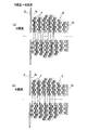
この実施形態では、2本の線材2の巻線方法について特徴を有する。図4に、ボビン3におけるコイル4を側面図により示す。図5に、ボビン3におけるコイル4を背面図により示す。図6(a)〜(d)に、図4におけるA視図、B視図、C視図及びD視図をそれぞれ示す。図7に、ボビン3におけるコイル4の配列を模式的に示す。図4〜7に示すように、この実施形態では、ボビン3の筒部3aの外周の4面のうち一対をなす平行面としての上面及び下面のうち下面側にて線材2の0.5本分のレーンチェンジを行い、上面側にて線材2の1.5本分のレーンチェンジを行うように2本の線材2の整列巻き回しを行っている(以下、この巻線方法を「1.5−0.5チェンジ」と言う。)。これにより、ボビン3の上下で2本分のレーンチェンジを行うようになっている。
This embodiment is characterized by the winding method of the two
すなわち、図4及び図5、並びに図6(a)に「1」で示すように、上部から巻き始めた2本の線材2は、左部にて第1鍔部3bに沿って垂直に巻かれ下部に至る。次に、下部にて図6(b)に「1」で示すように、線材2の0.5本分だけ斜めにレーンチェンジが行われ、右部にて垂直に巻かれて上部に至る。次に、上部にて図6(a)に「1」及び「2」で示すように、線材2の1.5本分だけ斜めにレーンチェンジが行われ、再び左部にて垂直に巻かれて下部に至る。その後、上記と同様に下部及び上部でレーンチェンジが繰り返し行われることにより、コイル4の第1段目が形成される(図6(a),(b)において第1段目は、「1〜6」の数字で示される。)。第1段目の巻き回しが終わると、巻き始め位置の反対側にて折り返され、図6(b)に示すように、下部では第1段目とは逆向きに線材2の0.5本分だけレーンチェンジが行われる。その後、図6(a)に示すように、上部では第1段目とは逆向きに線材2の1.5本分だけレーンチェンジが行われる。
That is, as indicated by “1” in FIGS. 4, 5, and 6 (a), the two
ここで、対比のために本実施形態における「1.5−0.5チェンジ」の巻線方法とは異なる巻線方法について説明する。図8(a)〜(d)に、図4におけるA視図、B視図、C視図及びD視図をそれぞれ示す。図9に、ボビン3におけるコイル4の配列を模式的に示す。図8,9に示す巻線方法では、ボビン3の筒部3aの外周の4面のうち一対をなす上面及び下面のうち下面側にて線材2の0本分のレーンチェンジを行い(つまり、レーンチェンジを行わない)、上面側にて線材2の2本分のレーンチェンジを行うように2本の線材2を整列に巻き回す(以下、この巻線方法を「2−0チェンジ」と言う。)。これにより、ボビン3の上下で2本分のレーンチェンジを行うようになっている。この巻線方法では、巻き回しの折り返し部分で、図8(a)に示す斜線部分にて図8(c)に示すように、線材2が3段に交差して重なり、鎖線円S1で示すような瘤ができることとなる。
Here, for comparison, a winding method different from the “1.5-0.5 change” winding method in the present embodiment will be described. FIGS. 8A to 8D show an A view, a B view, a C view, and a D view in FIG. 4, respectively. FIG. 9 schematically shows the arrangement of the
一方、図10(a)〜(d)に、図4におけるA視図、B視図、C視図及びD視図をそれぞれ示す。図11に、ボビン3におけるコイル4の配列を模式的に示す。図10,11に示すように、この実施形態では、ボビン3の筒部3bの外周の4面のうち一対をなす上面及び下面のうち下面側にて線材2の1本分のレーンチェンジを行い、上面側にて線材2の1本分のレーンチェンジを行うように2本の線材2の整列巻き回しを行っている(以下、この巻線方法を「1−1チェンジ」と言う。)。これにより、ボビン3の上下で2本分のレーンチェンジを行うようなっている。この巻線方法では、巻き回しの折り返し部分で、図11に示すように、ボビン3の端部を巻き終わり位置としたときに、その位置にて2本の線材2のうち1本の巻き余りが生じることとなる。
On the other hand, FIGS. 10A to 10D show an A view, a B view, a C view, and a D view in FIG. 4, respectively. FIG. 11 schematically shows the arrangement of the
以上説明したこの実施形態における矩形コイル1及びその巻線方法によれば、ボビン3における筒部3aの外周の4面のうち一対をなす上面及び下面のうち下面側にて線材2の0.5本分のレーンチェンジが行われ、上面側にて線材2の1.5本分のレーンチェンジが行われる。従って、図8,9に示すようにボビン3の上面のみで線材2本分のレーンチェンジを行う「2−0チェンジ」の巻線方法に比べて、本実施形態の巻線方法では、線材2の傾きが少なく、巻き回しの折り返し部分であるボビン3の各鍔部3b,3cにてコイル4の上下の段の交差が少なくなる。また、図10,11に示すようにボビン3の上面及び下面で線材1本分ずつレーンチェンジを行う「1−1チェンジ」の巻線方法とは異なり、この実施形態の巻線方法では、ボビン3の各鍔部3b,3cを巻き終わり位置としたときに、その位置にて1本の巻き余りが生じることがない。このため、矩形コイル1について、2本の線材2を同時に巻き回す整列巻き回しにつき、巻き回しの折り返し部分における瘤の発生を抑えることができ、これによってコイル4の外形状の拡大を抑えてコイル4をコンパクト化することができる。
According to the
ここで、例えば、図12に示すように、この矩形コイル1を、台形コイル11と交互にステータコア12のティース12aに組み付けてステータ13を構成することが考えられる。この場合では、矩形コイル1のコイル4につき、巻き回しの折り返し部分で瘤の発生を抑えてコンパクト化できることから、図13に拡大して示すように、矩形コイル1のコイル4と、それに隣接する台形コイル11のコイル4との間で所要の距離を確保することができる。このため、矩形コイル1と台形コイル11の組み付けの占積率を高めることができ、両者1,11の間の絶縁性を担保することができ、延いては上記ステータ13を使用したモータ性能を確保することができる。
Here, for example, as shown in FIG. 12, it can be considered that the
また、この実施形態の巻線方法を使用して製造された矩形コイル1は、2本の線材2をボビン3に対して同時に整列に巻き回しているので、矩形コイル1としての渦電流損を低減することができ、モータに使用されることでモータの高出力化に寄与することができる。加えて、矩形コイル1の生産性を向上させることができる。
Moreover, since the
[第2実施形態]
次に、本発明の巻線方法を台形コイルに具体化した第2実施形態につき図面を参照して詳細に説明する。
[Second Embodiment]
Next, a second embodiment in which the winding method of the present invention is embodied as a trapezoidal coil will be described in detail with reference to the drawings.
尚、この実施形態で、前記第1実施形態と同じ構成要素については同一の符号を付して説明を省略し、以下には異なった点を中心に説明する。 In this embodiment, the same components as those in the first embodiment are denoted by the same reference numerals, and the description thereof is omitted. Hereinafter, different points will be mainly described.
図14に、本実施形態の台形コイル11を側面図により示す。図15に、台形コイル11を正面図(図14のD視図)により示す。この実施形態の台形コイル11は、矩形断面を有するボビン3の外周の4面に2本の線材2を同時に整列に巻き回すことで製造され、巻き回されたコイル4の断面が台形をなしてる。この台形コイル11は、図12,13に示すように、ステータコア12のティース12aに矩形コイル1と交互に組み付けられてステータ13を構成するために使用される。
FIG. 14 shows a side view of the
この実施形態で、ボビン3は、第2鍔部3cが第1鍔部3bよりも小さくなっている以外は、第1実施形態のボビン3とほぼ同じ構成を有する。この実施形態でも、2本の線材2の巻線方法につき、第1実施形態と同様の方法が採用される。ここで、図16(a),(b)〜図21(a),(b)は、ボビン3における線材2の巻き回しの過程を示し、丸の中の数字は巻き回しの順番を示す。各図16〜21において、(a)はボビン3のリード側、すなわち図14のA視図(ボビン3の上部)を示し、(b)はボビン3の反リード側、すなわち図14のB視図(ボビン3の下部)を示す。ここで、図16〜21に示すように、この実施形態でも、ボビン3の筒部の外周の4面のうち一対をなす平行面としての上面及び下面のうち下面側にて線材2の0.5本分のレーンチェンジを行い、上面側にて線材2の1.5本分のレーンチェンジを行うように2本の線材2の整列巻き回しを行っている(「1.5−0.5チェンジ」)。これにより、ボビン3の上下で2本分のレーンチェンジを行うようになっている。
In this embodiment, the
ここで、台形断面を有するコイル4を形成するために、図16〜18に示すように、第1段目から第5段目まではボビン3の筒部のほぼ全域で線材2を巻き回すが、その後、図19〜21に示すように、コイル4の列を順次減らすことで、図21に示すように、最終的に合計10段の台形断面を有するコイル4を形成している。
Here, in order to form the
従って、この実施形態でも、台形コイル11につき、第1実施形態と同様の作用効果を得ることができる。また、この実施形態では、図12,13において、矩形コイル1と台形コイル11の両方につき、「1.5−0.5チェンジ」の巻線方法によるコイル4を使用している。このため、矩形コイル1と台形コイル11の組み付けの占積率を高めることができ、両者1,11の間の絶縁性をより確実に保つことができ、延いてはモータ性能の信頼性を高めることができる。
Therefore, also in this embodiment, the same effect as the first embodiment can be obtained for the
尚、この発明は前記各実施形に限定されるものではなく、発明の趣旨を逸脱することのない範囲で構成の一部を適宜に変更して実施することもできる。 The present invention is not limited to the above-described embodiments, and a part of the configuration can be changed as appropriate without departing from the spirit of the invention.
1 矩形コイル
2 線材
3 ボビン
4 コイル
11 台形コイル
1
Claims (2)
前記外周の4面のうち一対をなす平行面の一方側にて前記線材の0.5本分のレーンチェンジを行い、前記平行面の他方側にて前記線材の1.5本分のレーンチェンジを行うことにより、前記線材の巻き余りを発生させないこと、
前記ボビンに有している前記矩形断面をなす筒部の長さは、前記線材の2本分の整数倍プラス0.5本分であることを特徴とする巻線方法。 A winding method in which two wires are wound in alignment on four outer peripheral surfaces of a bobbin having a rectangular cross section,
A lane change for 0.5 wires is performed on one side of a pair of parallel surfaces among the four outer peripheral surfaces, and a lane change for 1.5 wires is performed on the other side of the parallel surfaces. by performing, that does not generate wind remainder of the wire,
The length of the cylinder part which makes the said rectangular cross section which the said bobbin has is the integral multiple of 2 pieces of the said wire, and 0.5 part length, The winding method characterized by the above-mentioned .
前記外周の4面のうち一対をなす平行面の一方側にて前記線材の0.5本分のレーンチェンジを行い、前記平行面の他方側にて前記線材の1.5本分のレーンチェンジを行うことにより、前記線材の巻き余りを発生させないこと、
前記ボビンに有している前記矩形断面をなす筒部の長さは、前記線材の2本分の整数倍プラス0.5本分であることを特徴とするコイル。 A coil formed by winding two wires in an aligned manner on the four outer peripheral surfaces of a bobbin having a rectangular cross section,
A lane change for 0.5 wires is performed on one side of a pair of parallel surfaces among the four outer peripheral surfaces, and a lane change for 1.5 wires is performed on the other side of the parallel surfaces. by performing, that does not generate wind remainder of the wire,
The length of the cylinder part which makes the said rectangular cross section which the said bobbin has is the integral multiple of the said 2 wire | line + 0.5 piece of coils characterized by the above-mentioned.
Priority Applications (6)
| Application Number | Priority Date | Filing Date | Title |
|---|---|---|---|
| JP2005373322A JP4396629B2 (en) | 2005-12-26 | 2005-12-26 | Winding method and coil |
| PCT/JP2006/322429 WO2007074587A1 (en) | 2005-12-26 | 2006-11-02 | Winding method and coil unit |
| CN2006800494471A CN101346782B (en) | 2005-12-26 | 2006-11-02 | Winding method and coil unit |
| US12/085,910 US7868726B2 (en) | 2005-12-26 | 2006-11-02 | Winding method and coil unit |
| KR1020087018304A KR101031955B1 (en) | 2005-12-26 | 2006-11-02 | Winding method and coil unit |
| EP06832482.1A EP1966808B1 (en) | 2005-12-26 | 2006-11-02 | Winding method and coil unit |
Applications Claiming Priority (1)
| Application Number | Priority Date | Filing Date | Title |
|---|---|---|---|
| JP2005373322A JP4396629B2 (en) | 2005-12-26 | 2005-12-26 | Winding method and coil |
Publications (2)
| Publication Number | Publication Date |
|---|---|
| JP2007180056A JP2007180056A (en) | 2007-07-12 |
| JP4396629B2 true JP4396629B2 (en) | 2010-01-13 |
Family
ID=37693613
Family Applications (1)
| Application Number | Title | Priority Date | Filing Date |
|---|---|---|---|
| JP2005373322A Active JP4396629B2 (en) | 2005-12-26 | 2005-12-26 | Winding method and coil |
Country Status (6)
| Country | Link |
|---|---|
| US (1) | US7868726B2 (en) |
| EP (1) | EP1966808B1 (en) |
| JP (1) | JP4396629B2 (en) |
| KR (1) | KR101031955B1 (en) |
| CN (1) | CN101346782B (en) |
| WO (1) | WO2007074587A1 (en) |
Families Citing this family (19)
| Publication number | Priority date | Publication date | Assignee | Title |
|---|---|---|---|---|
| KR100925916B1 (en) | 2007-12-12 | 2009-11-09 | 현대자동차주식회사 | Brushless motor |
| JP5334712B2 (en) * | 2009-07-02 | 2013-11-06 | 本田技研工業株式会社 | Winding method |
| DE102011002336A1 (en) * | 2011-04-29 | 2012-10-31 | Hella Kgaa Hueck & Co. | Projection headlights for vehicles |
| CN102810394B (en) * | 2011-05-31 | 2014-10-29 | 美桀电子科技(深圳)有限公司 | Coil winding method |
| EP2560269A3 (en) * | 2011-08-16 | 2017-10-18 | LG Innotek Co., Ltd. | Stator of Motor |
| WO2013031004A1 (en) * | 2011-09-01 | 2013-03-07 | 三菱電機株式会社 | Winding, winding method, and rotating electrical machine for vehicle |
| CN102976151A (en) * | 2011-09-05 | 2013-03-20 | 深圳市沃尔核材股份有限公司 | Wire or pipe packaging method |
| CN104137392B (en) * | 2012-06-21 | 2017-09-22 | 三菱电机株式会社 | Electric rotating machine |
| KR101468821B1 (en) | 2012-12-19 | 2014-12-03 | 티디케이가부시기가이샤 | Common mode filter |
| JP1527265S (en) * | 2015-01-21 | 2015-06-22 | ||
| CA163385S (en) * | 2015-01-21 | 2016-05-24 | Nat Inst Of Advanced Ind Scien | Molded coil |
| WO2016139764A1 (en) | 2015-03-04 | 2016-09-09 | 株式会社日立産機システム | Axial gap type rotating electric machine and stator |
| JP6547373B2 (en) * | 2015-03-31 | 2019-07-24 | Tdk株式会社 | Coil device and method of manufacturing coil device |
| KR102546479B1 (en) | 2016-09-28 | 2023-06-21 | 한국전기연구원 | Method for winding rectangular coil of high density for electric motor |
| WO2018221565A1 (en) * | 2017-06-02 | 2018-12-06 | デンソートリム株式会社 | Rotary electric machine and method for manufacturing rotary electric machine |
| KR102105705B1 (en) * | 2019-01-30 | 2020-04-28 | 주식회사 몹티콘 | Apparatus and method for detecting overspeeding-vehicle |
| CN111525760B (en) * | 2020-06-03 | 2022-04-05 | 北京萃丰资本投资有限公司 | Winding process of motor winding coil and motor winding coil |
| US11705768B2 (en) | 2021-05-18 | 2023-07-18 | Caterpillar Inc. | Twisted coil structures for an electric motor and systems, components, assemblies, and methods thereof |
| WO2024195052A1 (en) * | 2023-03-22 | 2024-09-26 | 三菱電機株式会社 | Stator, electric motor, compressor, refrigeration cycle device, and winding method |
Family Cites Families (19)
| Publication number | Priority date | Publication date | Assignee | Title |
|---|---|---|---|---|
| US1456108A (en) * | 1923-05-22 | Coil and spool construction | ||
| US2937350A (en) | 1954-12-13 | 1960-05-17 | Sasaki Shiro | Transformer and the like |
| US2930014A (en) * | 1954-12-24 | 1960-03-22 | Philips Corp | Polygonal electric coil |
| FR2181464B1 (en) * | 1972-04-25 | 1976-08-06 | Barthalon Maurice | |
| US4352081A (en) * | 1980-10-22 | 1982-09-28 | Kijima Musen Kabushiki Kaisha | Compact trans core |
| US4454492A (en) * | 1982-04-14 | 1984-06-12 | Laser Drive, Inc. | Low intra-winding capacitance multiple layer transformer winding |
| US4988055A (en) * | 1988-05-25 | 1991-01-29 | Nippondenso Co., Ltd. | Coil assembly for polygonal wire |
| JP3169314B2 (en) * | 1995-01-20 | 2001-05-21 | 日特エンジニアリング株式会社 | Multilayer coil and its winding method |
| US20010015393A1 (en) * | 1998-02-24 | 2001-08-23 | Hiroshi Miyazaki | Winding apparatus |
| JP2000245092A (en) | 1998-12-24 | 2000-09-08 | Toyota Motor Corp | Concentrated winding coil and winding manufacturing equipment |
| JP2000348959A (en) | 1999-03-29 | 2000-12-15 | Toyota Motor Corp | Winding device |
| JP2002008931A (en) * | 2000-04-18 | 2002-01-11 | Taiyo Yuden Co Ltd | Wound type common-mode choke coil |
| CN1165059C (en) * | 2001-07-23 | 2004-09-01 | 广家声 | Square winding winding method and application |
| JP2003100531A (en) | 2001-09-27 | 2003-04-04 | Murata Mfg Co Ltd | Common mode choke coil |
| JP3666748B2 (en) * | 2002-05-10 | 2005-06-29 | 株式会社デンソー | Winding device and winding method |
| JP4297323B2 (en) | 2002-09-30 | 2009-07-15 | Tdk株式会社 | Multi-wire coil winding method |
| JP4148115B2 (en) * | 2003-12-02 | 2008-09-10 | 株式会社村田製作所 | Coil winding method and coil component using the same |
| TW200636771A (en) | 2005-03-03 | 2006-10-16 | Nittoku Eng | Multilayer coil, winding method of same, and winding apparatus of same |
| JP4945105B2 (en) | 2005-08-31 | 2012-06-06 | 日特エンジニアリング株式会社 | Multi-layer coil winding method |
-
2005
- 2005-12-26 JP JP2005373322A patent/JP4396629B2/en active Active
-
2006
- 2006-11-02 KR KR1020087018304A patent/KR101031955B1/en active IP Right Grant
- 2006-11-02 EP EP06832482.1A patent/EP1966808B1/en active Active
- 2006-11-02 WO PCT/JP2006/322429 patent/WO2007074587A1/en active Application Filing
- 2006-11-02 CN CN2006800494471A patent/CN101346782B/en active Active
- 2006-11-02 US US12/085,910 patent/US7868726B2/en active Active
Also Published As
| Publication number | Publication date |
|---|---|
| JP2007180056A (en) | 2007-07-12 |
| CN101346782B (en) | 2011-10-19 |
| KR101031955B1 (en) | 2011-04-29 |
| CN101346782A (en) | 2009-01-14 |
| EP1966808A1 (en) | 2008-09-10 |
| KR20080081987A (en) | 2008-09-10 |
| US20090167475A1 (en) | 2009-07-02 |
| EP1966808B1 (en) | 2013-06-26 |
| WO2007074587A1 (en) | 2007-07-05 |
| US7868726B2 (en) | 2011-01-11 |
Similar Documents
| Publication | Publication Date | Title |
|---|---|---|
| JP4396630B2 (en) | Winding method and coil | |
| JP4396629B2 (en) | Winding method and coil | |
| JP5379550B2 (en) | Armature | |
| KR100323313B1 (en) | Stator of vehicle alternator | |
| JP6162438B2 (en) | Hollow cylindrical air core winding | |
| JP6369293B2 (en) | Rotating electric machine stator | |
| JP2012182972A (en) | Coil, stator, and method for manufacturing coil | |
| JP6351866B2 (en) | Rotating electric machine | |
| JP5082524B2 (en) | Insulator, stator structure and manufacturing method | |
| JP5321983B2 (en) | Stator, rotating electric machine, and winding method | |
| JP4603810B2 (en) | Method for making two-layer lap winding | |
| JP2005117821A (en) | Stator for rotary electric machine | |
| US8225484B2 (en) | Method of manufacturing stator for electric rotating machine | |
| JP2014050180A (en) | Stator coil structure of a rotary electric machine | |
| JP4920499B2 (en) | Stator winding of rotating electric machine | |
| JP6216631B2 (en) | Armature and rotating machine | |
| CN117411222A (en) | Lap winding for an electric machine with a series connection on the outer diameter | |
| JP2002112483A (en) | Rotor of rotating electric machine | |
| JP4483241B2 (en) | 3-phase motor | |
| JP2009148084A (en) | Armature | |
| JP5799904B2 (en) | Stator winding | |
| JP3609979B2 (en) | Vehicle alternator stator | |
| CN116615856A (en) | Stator of rotating electrical machine, manufacturing method of stator of rotating electrical machine | |
| JP2005192373A (en) | Slotless motor and its manufacturing method |
Legal Events
| Date | Code | Title | Description |
|---|---|---|---|
| A131 | Notification of reasons for refusal |
Free format text: JAPANESE INTERMEDIATE CODE: A131 Effective date: 20090210 |
|
| A521 | Request for written amendment filed |
Free format text: JAPANESE INTERMEDIATE CODE: A523 Effective date: 20090408 |
|
| A02 | Decision of refusal |
Free format text: JAPANESE INTERMEDIATE CODE: A02 Effective date: 20090519 |
|
| A521 | Request for written amendment filed |
Free format text: JAPANESE INTERMEDIATE CODE: A523 Effective date: 20090610 |
|
| A911 | Transfer to examiner for re-examination before appeal (zenchi) |
Free format text: JAPANESE INTERMEDIATE CODE: A911 Effective date: 20090826 |
|
| TRDD | Decision of grant or rejection written | ||
| A01 | Written decision to grant a patent or to grant a registration (utility model) |
Free format text: JAPANESE INTERMEDIATE CODE: A01 Effective date: 20090929 |
|
| A01 | Written decision to grant a patent or to grant a registration (utility model) |
Free format text: JAPANESE INTERMEDIATE CODE: A01 |
|
| A61 | First payment of annual fees (during grant procedure) |
Free format text: JAPANESE INTERMEDIATE CODE: A61 Effective date: 20091012 |
|
| FPAY | Renewal fee payment (event date is renewal date of database) |
Free format text: PAYMENT UNTIL: 20121030 Year of fee payment: 3 |
|
| R151 | Written notification of patent or utility model registration |
Ref document number: 4396629 Country of ref document: JP Free format text: JAPANESE INTERMEDIATE CODE: R151 |
|
| FPAY | Renewal fee payment (event date is renewal date of database) |
Free format text: PAYMENT UNTIL: 20121030 Year of fee payment: 3 |
|
| FPAY | Renewal fee payment (event date is renewal date of database) |
Free format text: PAYMENT UNTIL: 20131030 Year of fee payment: 4 |