JP4373465B2 - Joining method - Google Patents
Joining method Download PDFInfo
- Publication number
- JP4373465B2 JP4373465B2 JP2007253235A JP2007253235A JP4373465B2 JP 4373465 B2 JP4373465 B2 JP 4373465B2 JP 2007253235 A JP2007253235 A JP 2007253235A JP 2007253235 A JP2007253235 A JP 2007253235A JP 4373465 B2 JP4373465 B2 JP 4373465B2
- Authority
- JP
- Japan
- Prior art keywords
- joined
- frame
- pair
- deformed
- protrusion
- Prior art date
- Legal status (The legal status is an assumption and is not a legal conclusion. Google has not performed a legal analysis and makes no representation as to the accuracy of the status listed.)
- Expired - Fee Related
Links
- 238000005304 joining Methods 0.000 title claims description 45
- 238000000034 method Methods 0.000 title claims description 23
- 239000000463 material Substances 0.000 claims description 91
- 238000003780 insertion Methods 0.000 claims description 27
- 230000037431 insertion Effects 0.000 claims description 27
- 210000000078 claw Anatomy 0.000 claims description 23
- 238000005520 cutting process Methods 0.000 claims description 18
- 238000010008 shearing Methods 0.000 claims description 8
- 238000003825 pressing Methods 0.000 claims description 6
- 230000001154 acute effect Effects 0.000 claims description 2
- 238000004519 manufacturing process Methods 0.000 description 8
- 239000004566 building material Substances 0.000 description 4
- 238000005452 bending Methods 0.000 description 2
- 238000005034 decoration Methods 0.000 description 2
- 230000000694 effects Effects 0.000 description 2
- 238000003754 machining Methods 0.000 description 2
- 239000007769 metal material Substances 0.000 description 2
- 238000005219 brazing Methods 0.000 description 1
- 238000010586 diagram Methods 0.000 description 1
- 239000002184 metal Substances 0.000 description 1
- 238000012986 modification Methods 0.000 description 1
- 230000004048 modification Effects 0.000 description 1
- 230000009466 transformation Effects 0.000 description 1
Images


Landscapes
- Joining Of Corner Units Of Frames Or Wings (AREA)
- Insertion Pins And Rivets (AREA)
- Securing Of Glass Panes Or The Like (AREA)
Description
本発明は、接合方法に関し、詳しくは、一対の被接合材同士を接合する接合方法に関する。 The present invention relates to a bonding how, particularly, relates to joining how for joining together a pair of members to be joined.
従来、一対の被接合材同士を接合する構造として、例えば、窓枠や障子枠等を構成する枠材(框材)を枠組みする際に、互いに交差する一対の枠材(被接合材)の端部同士をビス止めによって接合する構造が一般的である。
ビス止めによる接合構造としては、互いに接合される枠材の一方にビスホールを設けておき、他方の枠材の外側から貫通させたビスをビスホールに螺合させる構造が用いられている。ところで、枠材としては金属製の押出形材が用いられることが多く、このような押出形材にビスホールを形成する場合には、長手方向の端部のみならず全長に渡って形成する必要があり、ビス止めによる接合構造では、金属材料の使用数量が増加してしまうというデメリットがある。
Conventionally, as a structure for joining a pair of materials to be joined, for example, when a frame material (frame material) constituting a window frame, a shoji frame or the like is framed, a pair of frame materials (materials to be joined) intersecting each other A structure in which the ends are joined by screws is common.
As a joining structure by screwing, a structure in which a screw hole is provided in one of the frame materials to be joined to each other and a screw penetrated from the outside of the other frame material is screwed into the screw hole is used. By the way, a metal extruded shape is often used as the frame material, and when forming a screw hole in such an extruded shape, it is necessary to form not only the longitudinal end but also the entire length. There is a demerit that the amount of metal material used increases in the joint structure with screws.
一方、ビス止めによる接合構造の他に枠材同士を接合する構造として、一方の枠材の端部に複数の突片(折曲片)を設け、他方の枠材に複数の挿通孔(透孔)を設けておき、挿通孔に挿通した突片の先端を折り曲げて接合する構造も利用されている(例えば、特許文献1参照)。
また、特許文献1に記載の接合構造に類似したものとして、挿通孔に挿通した突片の先端をハンマー等の刃で叩いてつぶし、突片の先端を板厚方向に拡大させることで枠材同士を接合する構造も考えられる。
以上のような突片と挿通孔とを用いた接合構造の場合、前記ビス止めによる接合構造と比較して、枠材の全長に渡ってビスホールを形成する必要がないことから、金属材料の使用量が抑制できるようになる。
On the other hand, as a structure for joining the frame members in addition to the joint structure using screws, a plurality of projecting pieces (folded pieces) are provided at the end of one frame member, and a plurality of insertion holes (transparent holes) are provided in the other frame member. There is also used a structure in which a hole) is provided and the tip of a protruding piece inserted through the insertion hole is bent and joined (see, for example, Patent Document 1).
Further, as similar to the joining structure described in
In the case of the joint structure using the projecting piece and the insertion hole as described above, it is not necessary to form a screw hole over the entire length of the frame member as compared with the joint structure by the screw fixing, and therefore the use of a metal material The amount can be suppressed.
しかしながら、特許文献1に記載の接合構造では、枠材に対して複数の突片や複数の挿通孔を加工する必要があるため、加工手間が過大になってしまい製造コストが増加するという問題がある。また、突片の先端をつぶし加工する接合構造では、ハンマーを扱う作業者の熟練度などによって加工精度にばらつきが生じやすく、加工に長時間かかるという問題がある。さらに、つぶし加工の場合には、突片を設けた一方の枠材の長手方向に向かってハンマーの打撃力を加えるため、その打撃力を大きくすると枠材自体が座屈する可能性があり、加工速度が高めにくいとともに、プレス機等を用いた自動化が図りにくいという欠点も有している。
However, in the joint structure described in
本発明の目的は、加工手間が軽減できるとともに接合部の強度のばらつきを抑えることができる接合方法を提供することにある。 An object of the present invention is to provide a bonding how that can suppress variations in strength of the joint together with the processing time can be reduced.
本発明の接合方法は、一対の被接合材を互いに接合する接合方法であって、前記一対の被接合材のうち、一方の被接合材は、その長手方向端部に他方の被接合材に向かって延びる板状の延出部を有し、他方の被接合材は、前記延出部を挿通可能な挿通孔が形成された
被接合面部を有しており、前記延出部の先端を両側から挟んで変形させるとともに、近づいた際に互いに噛み合い可能な爪部が形成された対向面を有する一対の挟持部材を用い、前記被接合面部の一方側から前記挿通孔に挿通した前記延出部の先端を当該被接合面部の他方側に突出させた状態で、前記一対の挟持部材を互いに近づく方向に移動させて前記延出部の先端を挟むとともに、当該各挟持部材の爪部の噛み合いで当該延出部の先端を少なくとも1箇所でせん断により切断して複数の突部に分割し、この切断位置を挟んで隣り合う突部を一方および他方の前記爪部で互いに逆方向に変形させ、変形させた各突部を前記被接合面部に当接させて一対の被接合材を互いに接合することを特徴とする。
The joining method of the present invention is a joining method for joining a pair of materials to be joined to each other, and one of the pair of materials to be joined is attached to the other material to be joined at its longitudinal end. The other material to be joined has a joined surface part in which an insertion hole through which the extending part can be inserted is formed, and the tip of the extending part is The extension that is inserted through the insertion hole from one side of the joined surface portion using a pair of clamping members that are deformed by being sandwiched from both sides and that are formed with claw portions that can mesh with each other when approaching. In a state where the tip of each part protrudes to the other side of the surface to be joined, the pair of clamping members are moved toward each other so as to sandwich the tips of the extending parts, and the claws of the respective clamping members are engaged. switching via shear in at least one place the tip of the extending portion And is divided into a plurality of protrusions, contact this protrusion adjacent to each other with the cutting position is deformed in opposite directions in one and the other of the claw portions, each protruding portion is deformed to the object to be bonded face And a pair of materials to be joined are joined together.
ここで、被接合材としては、互いに接合される任意の一対の部材であればよいが、例えば、サッシ窓等の建具に用いられる枠材(窓枠の枠材や障子の框材、額縁材等)、あるいは内装材や外装材等の各種の建材に用いられる部材などが例示できる。さらに、被接合材としては、建具や建材等以外に用いられる各種の構造材や装飾材などであってもよい。すなわち、本発明は、一対の被接合材同士を互いに接合する接合構造に広く適用可能である。 Here, as a material to be joined, any pair of members to be joined together may be used. For example, a frame material used for a fitting such as a sash window (a frame material of a window frame, a shoji frame material, a frame material) Etc.), or members used for various building materials such as interior materials and exterior materials. Furthermore, as a to-be-joined material, the various structural materials used in addition to joinery, building materials, etc., decoration materials, etc. may be sufficient. That is, the present invention can be widely applied to a joining structure in which a pair of materials to be joined are joined together.
以上の本発明によれば、一方の被接合材に板状の延出部を形成し、他方の被接合材に挿通孔を形成しておき、挿通孔に挿通させた延出部の先端を切断して複数の突部に分割するとともに、隣り合う突部を逆方向に変形させることで、予め複数の突部や挿通孔を形成しておく必要がなくなることから、加工手間を軽減させることができる。さらに、延出部の先端を切断、変形させることで、従来のハンマーを用いたつぶし加工と比較して、作業者の熟練度によるばらつきが生じにくくなり、接合部の加工精度を向上させ、接合部のがたつきを防止して接合強度を安定して確保することができる。また、従来のつぶし加工では、突片を設けた部材の長手方向に打撃力が加えられるのに対して、本発明では、延出部の板厚方向両側から挟持することで、被接合材の長手方向に挟持力が作用せず(あるいは、非常に小さな力しか作用せず)、被接合材の座屈が防止できる。従って、一度に加工する延出部の長さ寸法を長くしたり形成する突部の数を多くしたりすることで、接合強度を高めることができるとともに、被接合材の座屈を防止しつつ加工速度を高めることもできる。 According to the present invention described above, a plate-like extension portion is formed in one of the materials to be joined, an insertion hole is formed in the other material to be joined, and the tip of the extension portion inserted through the insertion hole is formed. By cutting and dividing into a plurality of protrusions and deforming adjacent protrusions in the opposite direction, it is not necessary to form a plurality of protrusions and insertion holes in advance, thereby reducing the processing effort Can do. Furthermore, by cutting and deforming the tip of the extension part, it is less likely to cause variations due to the skill level of the operator compared to the conventional crushing process using a hammer, improving the processing accuracy of the joint part and joining. It is possible to prevent the rattling of the portion and to secure the bonding strength stably. Further, in the conventional crushing process, the striking force is applied in the longitudinal direction of the member provided with the projecting piece, whereas in the present invention, the material to be joined is sandwiched from both sides in the plate thickness direction of the extending portion. The clamping force does not act in the longitudinal direction (or only a very small force acts), and buckling of the materials to be joined can be prevented. Therefore, by increasing the length of the extended portion to be processed at one time or increasing the number of protrusions to be formed, it is possible to increase the bonding strength and prevent buckling of the materials to be bonded. The processing speed can also be increased.
さらに、一対の挟持部材に噛み合い可能な爪部を用いることで、延出部の先端を高精度にせん断して切断するとともに、切断に続いて停止することなく突部を変形させることができ、加工精度および加工速度をともに高めることができる。 Furthermore , by using claw portions that can mesh with a pair of clamping members, the tip of the extension portion can be sheared and cut with high accuracy, and the protrusion can be deformed without stopping following cutting, Both processing accuracy and processing speed can be increased.
さらに、本発明の接合方法では、前記爪部は、前記被接合面部の他方側の表面との間で鋭角を成すように傾斜する傾斜面を有して形成されており、前記せん断により切断した突部を前記傾斜面で押圧することで、当該突部を曲げ変形させる構成が採用できる。
このような構成によれば、比較的小さな挟持力で延出部の先端を切断しながら曲げ変形させることができる。
また、本発明の枠体の製造方法では、前記爪部は、前記被接合面部の他方側の表面に略直交する垂直面を有して形成されており、前記せん断により切断した突部を前記垂直面で押圧することで、前記挟持部材の移動方向にずらすように当該突部を変形させる構成を採用してもよい。
このような構成によれば、被接合面部の他方側への延出部先端の突出量が小さくても、確実に延出部を切断して突部を変形させることができ、加工後の突部が目立たずかつ邪魔にならないようにできる。
Furthermore, in the joining method of the present invention, the claw portion is formed to have an inclined surface that is inclined so as to form an acute angle with the surface on the other side of the joined surface portion, and is cut by the shearing. A configuration in which the protrusion is bent and deformed by pressing the protrusion with the inclined surface can be employed.
According to such a configuration, it is possible to bend and deform while cutting the tip of the extending portion with a relatively small clamping force.
In the method for manufacturing a frame of the present invention, the claw portion is formed to have a vertical surface substantially orthogonal to the surface on the other side of the bonded surface portion, and the protrusion cut by the shearing You may employ | adopt the structure which deform | transforms the said protrusion so that it may shift to the moving direction of the said clamping member by pressing on a perpendicular surface.
According to such a configuration, even if the protrusion amount of the extension part tip to the other side of the joined surface part is small, the extension part can be reliably cut and the protrusion can be deformed. The part can be made inconspicuous and out of the way.
一方、本発明の接合構造は、一対の被接合材を互いに接合する接合構造であって、前記一対の被接合材のうち、一方の被接合材は、その長手方向端部から他方の被接合材に向かって延びる板状の延出部を有し、他方の被接合材は、前記延出部を挿通可能な挿通孔が形成された被接合面部を有しており、前記被接合面部の一方側から前記挿通孔に挿通されて当該被接合面部の他方側に突出した前記延出部の先端は、少なくとも1箇所で切断されて複数の突部に分割されるとともに、この切断位置を挟んで隣り合う突部が互いに逆方向に変形されて前記被接合面部に当接されていることを特徴とする。
このような本発明によれば、前述の接合方法で説明したように被接合材同士を接合することができるので、加工精度を高めて接合強度が安定して確保できる。
On the other hand, the joining structure of the present invention is a joining structure for joining a pair of materials to be joined to each other, and one of the pair of materials to be joined is connected to the other to be joined from its longitudinal end. A plate-like extension portion extending toward the material, and the other material to be joined has a joined surface portion in which an insertion hole through which the extending portion can be inserted is formed. The tip of the extended portion that is inserted into the insertion hole from one side and protrudes to the other side of the surface to be joined is cut at at least one location and divided into a plurality of protrusions, and the cutting position is sandwiched between them. The adjacent protrusions are deformed in opposite directions and are in contact with the surface to be joined.
According to the present invention as described above, since the materials to be joined can be joined as described in the joining method described above, it is possible to improve the processing accuracy and stably secure the joining strength.
この際、本発明の接合構造では、前記複数に分割された各々の突部の長さ寸法がそれぞれ略同一に設定されるとともに、互いに逆方向に変形された突部の数が同数に設定されていることが好ましい。
このような構成によれば、互いに逆方向に変形された突部の長さ寸法および数が同じに設定されていることで、個々の突部に作用する接合力が均等になり、特定の突部から先行して破断するような破壊状態となることが防止でき、接合強度を一層向上させることができる。さらに、突部を逆方向に変形させる際の挟持力の不均等がなくなり、加工時の反力が発生しにくくできることから、製造装置の簡略化を図ることができる。
At this time, in the joining structure of the present invention, the lengths of the plurality of protrusions divided into the plurality are set to be substantially the same, and the number of protrusions deformed in opposite directions is set to the same number. It is preferable.
According to such a configuration, the length dimension and the number of the protrusions deformed in the opposite directions are set to be the same, so that the bonding force acting on each protrusion becomes uniform, and the specific protrusion It is possible to prevent a rupture state that breaks in advance from the portion, and to further improve the bonding strength. Furthermore, since the non-uniformity of the clamping force when the protrusion is deformed in the reverse direction is eliminated and the reaction force during processing is less likely to occur, the manufacturing apparatus can be simplified.
また、本発明の接合構造では、前記隣り合う突部同士が一部で接触して形成されていることが好ましい。
このような構成によれば、隣り合う突部同士が一部で接触している、つまり延出部を切断して変形させる際に、突部同士が完全に離隔しないように変形されていることで、突部の基端部分が互いに連続した状態に形成されていることから、外力が作用した際に各突部同士での力の伝達が可能になる。従って、突部の破断強度を高めることができ、被接合材同士の接合強度を確保することができる。
Moreover, in the joining structure of this invention, it is preferable that the said adjacent protrusions are formed in contact in part.
According to such a configuration, adjacent protrusions are in contact with each other, that is, when the extension part is cut and deformed, the protrusions are deformed so as not to be completely separated from each other. Thus, since the base end portions of the protrusions are formed in a continuous state, the force can be transmitted between the protrusions when an external force is applied. Therefore, the breaking strength of the protrusion can be increased, and the bonding strength between the materials to be bonded can be ensured.
また、本発明の建具は、枠体と、この枠体に支持される面材とを備えた建具であって、前記枠体および面材の少なくとも一方を構成する一対の部材同士が前記いずれかの接合構造で接合されていることを特徴とする。
ここで、枠体としては、上下左右の枠材が四周枠組みされて建物に固定される窓枠、ドア枠、開口枠等の建具枠が例示でき、面材としては、上下左右の框材が四周框組みされた内部にパネルを保持した可動障子や固定障子が例示できる。そして、枠体や面材において、その構成部材である枠材や框材によって被接合材が構成されていればよい。すなわち、本発明の建具は、各種の開閉形式を有した窓や出入り口、あるいは開閉不能な嵌め殺し窓など、任意のものが採用可能である。また、一方の被接合材を上枠および下枠(または上框および下框)とし、他方の被接合材を左右の縦枠(または左右の縦框)としてもよく、また一方の被接合材を左右の縦枠(または左右の縦框)とし、他方の被接合材を上枠および下枠(または上框および下框)としてもよい。
このような建具によれば、前述の接合方法や接合構造と略同様の効果が得られるとともに、一方の被接合材の両端部に延出部を形成し、その両側に位置する他方の被接合材の両方に挿通孔を形成するようにしておけば、両側から同時に接合作業を実施することで、作業時に枠体や障子の框材に作用する力が釣り合うようにできる。
Moreover, the joinery of the present invention is a joinery comprising a frame and a face material supported by the frame, and the pair of members constituting at least one of the frame and the face material are either of the above It is characterized by being joined by the joining structure.
Here, examples of the frame body include window frames, door frames, opening frames, and other joinery frames that are fixed to the building by the upper, lower, left, and right frame members being quadrilaterally framed. A movable shoji or fixed shoji that holds a panel inside the four-sided frame can be exemplified. And in a frame and a face material, the to-be-joined material should just be comprised with the frame material and brazing material which are the structural members. In other words, the fittings of the present invention can employ arbitrary things such as windows and doorways having various types of opening and closing, or fitting windows that cannot be opened and closed. Also, one material to be bonded may be an upper frame and a lower frame (or upper and lower frames), and the other material to be bonded may be left and right vertical frames (or left and right vertical frames). May be left and right vertical frames (or left and right vertical rods), and the other material to be joined may be an upper frame and a lower frame (or upper and lower rods).
According to such a joinery, substantially the same effects as those of the joining method and the joining structure described above can be obtained, and the extension parts are formed at both ends of one of the joined materials, and the other joined parts located on both sides thereof. If the insertion holes are formed in both of the materials, it is possible to balance the forces acting on the frame body and the shoji screen material by performing the joining work simultaneously from both sides.
以下、本発明の各実施形態を図面に基づいて説明する。
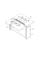
図1は、本発明の実施形態に係る建具を構成する窓枠Wの要部を示す斜視図である。図2は、窓枠Wの枠組み前の状態を示す斜視図である。
図1、図2において、枠体としての窓枠Wは、建物の外壁などに設けられ、その内部に図示しない障子や固定パネル材等を支持してサッシ窓を構成するものであり、それぞれアルミ形材製の上枠、下枠および左右の縦枠を四周枠組みして構成されている。
なお、図1、図2には、上枠、下枠および左右の縦枠のうち、一方の被接合材としての上枠1における一方の端部と、他方の被接合材としての縦枠2における上端部との接合構造を一例として示している。
この場合、図示を省略した上枠1の他方の端部と、他方の縦枠2における上端部とが図1、図2に示すのと同一の接合構造で接合されている。さらに、一方の被接合材としての下枠の端部と、他方の被接合材としての縦枠2における下端部との接合構造も同様である。
Hereinafter, each embodiment of the present invention will be described with reference to the drawings.
FIG. 1 is a perspective view showing a main part of a window frame W constituting a fitting according to an embodiment of the present invention. FIG. 2 is a perspective view showing a state of the window frame W before the frame.
In FIGS. 1 and 2, a window frame W as a frame is provided on an outer wall of a building, and constitutes a sash window by supporting a shoji, a fixed panel material, etc. (not shown) in the interior. It consists of a four-frame frame consisting of an upper frame, a lower frame, and left and right vertical frames.
In FIG. 1 and FIG. 2, among the upper frame, the lower frame, and the left and right vertical frames, one end portion of the
In this case, the other end of the upper frame 1 (not shown) and the upper end of the other
上枠1は、全体長尺状かつ断面略H字形に形成され、その断面において、見込み方向(室内外方向であり、図にXで示す方向)に沿って延びる見込み面部11と、この見込み面部11の室内側にて見付け方向(上枠1の長手方向および見込み方向に直交する方向であり、図にZで示す方向)に延びる室内見付け面部12と、見込み面部11の室外側にて見付け方向に延びる室外見付け面部13とを有して構成されている。一方、縦枠2は、全体長尺状かつ断面略H字形に形成され、その断面において、見込み方向(室内外方向)に沿って延びる見込み面部21と、この見込み面部21の室内側にて見付け方向(縦枠2の長手方向および見込み方向に直交する方向であり、図にYで示す方向)に延びる室内見付け面部22と、見込み面部21の室外側にて見付け方向に延びる室外見付け面部23とを有して構成されている。そして、上枠1の室内見付け面部12および室外見付け面部13や、縦枠2の室内見付け面部22や室外見付け面部23は、それぞれ適宜に切欠き加工が施され、上枠1と縦枠2とを接合した際に、互いの室内見付け面部12,22同士および室外見付け面部13,23同士が同一面で連続するようになっている。また、上枠1の見込み面部11と縦枠2の見込み面部21とは、互いの平面方向を略直交させた状態で連続するようになっている。
The
また、図2に示すように、上枠1の長手方向端部における見込み面部11には、縦枠2に向かって延びる板状の延出部14が形成されている。一方、縦枠2の見込み面部21における延出部14に対応した位置には、延出部14を挿通可能な長孔状(スリット状)の挿通孔24が形成されている。すなわち、縦枠2の見込み面部21によって被接合面部が構成されている。そして、図1に示すように、上枠1の延出部14は、縦枠2の見込み面部21における一方側(見付け方向内側)から他方側(見付け方向外側)に向かって挿通孔24に挿通され、見込み面部21の他方側に突出して設けられている。このように突出した延出部14の先端は、少なくとも1箇所で切断されて複数の突部15に分割されるとともに、切断位置(切断部16)を挟んで隣り合う突部15が互いに逆方向に変形されて縦枠2の見込み面部21に当接されている。
In addition, as shown in FIG. 2, a plate-like extending
具体的には、図1に示すように、延出部14の先端は、5箇所の切断部16で切断され、6つの突部15に分割されている。6つの突部15は、それぞれ均等な長さ寸法に形成され、すなわち、各突部15の見込み方向に沿った長さ寸法が略同一に設定されている。また、6つの突部15のうち、3つの突部15Aが縦枠2の長手方向端部側に向かって変形され、他の3つの突部15Bが逆向きに向かって変形されており、これらの突部15Aと突部15Bとが交互に設けられている。さらに、互いに隣接する突部15A,15B同士は、一部で接触して形成され、つまり切断部16が延出部14を板厚方向に貫通しないように突部15が形成されている。
Specifically, as shown in FIG. 1, the distal end of the extending
次に、窓枠Wの製造装置について図3に基づき説明する。
図3(A),(B)は、製造装置における一対の挟持部材の非加力状態および加力状態を示す正面図である。
窓枠Wの製造装置は、窓枠Wを構成する枠材をセットするための図示しない載置台と、この載置台に位置調節自在に取り付けられる一対のプレス装置とを備えて構成されている。プレス装置は、前記延出部14を切断して突部15を変形させるもので、載置台上にセットした枠材のうち一方(本実施形態では、上枠1や下枠)の長手方向両端部に対応した位置に一対で設けられている。
Next, the manufacturing apparatus of the window frame W is demonstrated based on FIG.
FIGS. 3A and 3B are front views showing a non-forced state and a forced state of a pair of clamping members in the manufacturing apparatus.
The manufacturing apparatus for the window frame W includes a mounting table (not shown) for setting a frame material constituting the window frame W, and a pair of press devices that are attached to the mounting table so that the position thereof can be adjusted. The pressing device cuts the extending
プレス装置は、例えば、載置台にて互いに進退移動可能に支持された一対の挟持部材P1,P2を有しており、一対の挟持部材P1,P2が互いに近づくように移動して噛み合うように構成されている。
なお、一対の挟持部材P1,P2は、製造する窓枠Wの形態や仕様等に応じて適宜取り替え可能に構成されている。
The press device has, for example, a pair of sandwiching members P1 and P2 that are supported on a mounting table so as to be able to move forward and backward, and the pair of sandwiching members P1 and P2 are configured to move and mesh with each other. Has been.
Note that the pair of sandwiching members P1 and P2 are configured to be appropriately replaceable according to the form and specifications of the window frame W to be manufactured.
一対の挟持部材P1,P2は、前記延出部14の先端を両側から挟んで変形させるもので、それらの対向面には、図3に示すように、近づいた際に互いに噛み合い可能な複数の爪部P11,P21が形成されている。すなわち、一方の挟持部材P1には、前記3つの突部15Aに対応した3つの爪部P11が形成され、他方の挟持部材P2には、前記3つの突部15Bに対応した3つの爪部P21が形成されている。そして、一方および他方の爪部P11,P21同士が交互に位置して互いに噛み合うことで、前記延出部14の先端をせん断により切断するとともに、切断して形成した突部15Aと突部15Bとを互いに逆向きに変形させるように構成されている。
The pair of sandwiching members P1 and P2 are deformed by sandwiching the distal end of the extending
次に、窓枠Wの製造方法(枠材同士の接合手順)について図4〜図7に基づき説明する。なお、ここでは、一方の被接合材としての上枠1と他方の被接合材としての縦枠2とを接合する接合手順について説明する。
図4(A)〜(C)および図6(A)〜(C)は、それぞれ枠材同士の接合手順を説明する図である。ここで、図4(A)および図6(A)は、それぞれプレス装置の非加力状態を示し、図4(B)および図6(B)は、それぞれプレス装置の加力状態を示している。また、図5および図7は、それぞれ加工後の一方の被接合材(上枠1)を示す斜視図である。
Next, the manufacturing method (joining procedure of frame materials) of the window frame W is demonstrated based on FIGS. Here, a joining procedure for joining the
4 (A) to 4 (C) and FIGS. 6 (A) to 6 (C) are diagrams for explaining a joining procedure between frame members. Here, FIG. 4 (A) and FIG. 6 (A) show the non-force state of the press device, respectively, and FIG. 4 (B) and FIG. 6 (B) show the force state of the press device, respectively. Yes. FIG. 5 and FIG. 7 are perspective views showing one material to be joined (upper frame 1) after processing.
先ず、前述のような延出部14を両端部に形成した上枠1および下枠と、上下端部に挿通孔24を形成した一対の縦枠2とを準備し、延出部14を挿通孔24に挿通した状態で上枠1および下枠と縦枠2とを仮組みする。
そして、仮組みした上枠1と縦枠2との交差部分をプレス装置にセットする。この際、縦枠2の見込み面部21から突出した上枠1の延出部14が一対の挟持部材P1,P2の間に位置するとともに、図4(A)および図6(A)に示すように、挟持部材P1,P2の先端が縦枠2の見込み面部21に当接するような位置に、上枠1および縦枠2が位置決めされるようになっている。そして、図示を省略するが、上枠1の他方の端部側においても同様に、上枠1および縦枠2を他方のプレス装置にセットする。
First, the
And the intersection part of the
以上のように、上枠1および縦枠2をプレス装置にセットした状態において、スライド板を駆動部の駆動力により移動させることで、図4(B)、図6(B)に示すように、一対の挟持部材P1,P2が互いに近づく方向に移動し、その爪部P11,P21が延出部14の先端をせん断により切断するとともに、一方および他方の爪部P11,P21によって突部15A,15Bを互いに逆方向に変形させる。
ここで、図4に示す挟持部材P1,P2の爪部P11,P21には、縦枠2の見込み面部21に向かって開く方向に傾斜する傾斜面P12,P22(見込み面部21の他方側の表面との間で鋭角を成すように傾斜する傾斜面)が形成されており、延出部14の先端から基端側に向かってせん断するとともに、傾斜面P12,P22によって、図5に示すように、突部15A,15Bを曲げ変形させつつ見込み面部21に沿って変形させるように挟持部材P1,P2が構成されている。また、一方および他方の爪部P11,P21に形成された傾斜面P12,P22同士は、その先端が加力状態において重ならず、すなわち変形した突部15A,15B同士の基端部が互いに接触した状態となるように構成されている。
As described above, in the state where the
Here, the claw portions P11 and P21 of the sandwiching members P1 and P2 shown in FIG. 4 are inclined surfaces P12 and P22 (surfaces on the other side of the prospective surface portion 21) that incline toward the
一方、図6に示す挟持部材P1,P2の爪部P11,P21には、縦枠2の見込み面部21に略直交する垂直面P13,P23(見込み面部21の他方側の表面に略直交する垂直面)が形成されている。このような垂直面P13,P23を有した爪部P11,P21は、延出部14の先端をせん断により切断するとともに、さほど曲げ変形させることなく突部15A,15Bを見込み面部21に沿ってせん断変形させる。
また、一方および他方の爪部P11,P21に形成された垂直面P13,P23同士は、図6(B)に示すように加力状態において、その先端同士が重ならず、すなわち変形した突部15A,15B同士の一部が連続した状態(一体的に連続した状態)となるように構成されている。
以上のようにして上枠1の突部15を縦枠2の見込み面部21における挿通孔24縁部に当接させ、上枠1と縦枠2とを接合した後に、プレス装置の加力を解除してから、載置台から上枠1および縦枠2を取り外す。これに続いて、下枠と縦枠2とを上述と同様の手順で接合し、窓枠Wの接合作業が終了する。
On the other hand, the claw portions P11 and P21 of the clamping members P1 and P2 shown in FIG. 6 have vertical surfaces P13 and P23 that are substantially orthogonal to the
Further, the vertical surfaces P13 and P23 formed on the one and the other claw portions P11 and P21 do not overlap with each other in the applied state as shown in FIG. A part of 15A, 15B is configured to be continuous (integrally continuous).
As described above, the
このような本実施形態によれば、以下のような効果がある。
(1)すなわち、板状に形成した延出部14の先端を挟持部材P1,P2で切断して複数の突部15に分割するとともに、隣り合う突部15A,15Bを逆方向に変形させることで、予め複数の突部や挿通孔を形成しておく必要がなくなることから、加工手間を軽減させることができる。さらに、プレス装置の挟持部材P1,P2を用いて延出部14の先端を切断、変形させることで、加工の均質化を図って接合部の加工精度を向上させ、接合強度を確保することができるとともに、自動化を図ることで加工時間の短縮が可能になる。また、従来のように複数の突片と複数の挿通孔とを係合させる構造と比較し、本願発明では、1つの延出部14を複数の突部15A,15Bに分割することで、延出部14の長さ寸法(見込み方向の寸法)を従来より短くして省スペースでの接合が可能になるか、あるいは、同一のスペースにおいて延出部14の長さ寸法を長くしたり突部15A,15Bの数を増やしたりが可能になり、従来よりも接合強度を高めることができる。
According to this embodiment, there are the following effects.
(1) That is, the front end of the
(2)さらに、上枠1の延出部14を板厚方向両側から挟持部材P1,P2で挟持することで、プレス装置からの力が上枠1の長手方向に作用せず、第1枠材である上枠1や下枠の座屈が防止できる。従って、挟持部材P1,P2の挟持力を高めても枠材が座屈しにくくできるので、一度に加工する延出部14の見込み方向長さ寸法を長くしたり、形成する突部15の数を多くしたりして接合強度を高めることができる。
(2) Further, the force from the pressing device does not act in the longitudinal direction of the
(3)また、一対の挟持部材P1,P2に形成した噛み合い可能な爪部P11,P21によって延出部14の先端を加工することで、せん断による切断精度が高められるとともに、切断に続いて停止することなく突部15を変形させることができ、加工精度および加工速度をともに高めることができる。この際、傾斜面P12,P22を有した爪部P11,P21を用いれば、比較的小さな挟持力で延出部14の先端を切断することができる。一方、垂直面P13,P23を有した爪部P11,P21を用いれば、延出部14先端の突出量が小さくても確実に切断し、突部15をずらすように変形させることができる。
(3) Further, by cutting the tip of the extended
(4)また、互いに逆方向に変形された突部15A,15Bの長さ寸法および数が同じに設定されていることで、個々の突部15に作用する接合力が均等になり、特定の突部15から先行して破断するような破壊状態となることが防止でき、接合強度を一層向上させることができる。さらに、一対の挟持部材P1,P2で挟む力が釣り合うことで、加工時の反力が発生しにくくできることから、製造装置の簡略化を図ることができる。また、隣り合う突部15A,15B同士が一部で接触し、互いに連続した状態に形成されていることから、外力が作用した際に各突部15同士での力の伝達が可能になり、突部15の破断強度を高めることができる。
(4) Since the lengths and the numbers of the
なお、本発明は、前記実施形態に限定されるものではなく、本発明の目的を達成できる他の構成等を含み、以下に示すような変形等も本発明に含まれる。
例えば、前記実施形態においては、建具としてのサッシ窓に用いる窓枠W(枠体)を例示して説明したが、本発明における接合構造は、このようなサッシ窓に適用するもの限られず、出入り口の建具枠や、手摺り、フェンス、格子(面格子)、門扉、内装材や外装材等の各種の建材等に適用してもよい。また、本発明の接合構造は、窓枠Wに限らず、窓枠に支持される障子の框材(上框、下框、縦框)同士を接合するものでもよい。
さらに、被接合材としては、建具や建材等以外に用いられる各種の構造材や装飾材などであってもよい。すなわち、本発明は、一対の被接合材同士を互いに接合する接合構造に広く適用可能である。
In addition, this invention is not limited to the said embodiment, Including other structures etc. which can achieve the objective of this invention, the deformation | transformation etc. which are shown below are also contained in this invention.
For example, in the above-described embodiment, the window frame W (frame body) used for the sash window as a joinery has been described as an example. However, the joining structure in the present invention is not limited to the one applied to such a sash window, The present invention may also be applied to various building materials such as frame frames, handrails, fences, lattices (face lattices), gates, interior materials and exterior materials. Further, the joining structure of the present invention is not limited to the window frame W, and may be ones that join the shoji screen materials (upper, lower, and vertical) supported by the window frame.
Furthermore, as a to-be-joined material, the various structural materials used in addition to joinery, building materials, etc., decoration materials, etc. may be sufficient. That is, the present invention can be widely applied to a joining structure in which a pair of materials to be joined are joined together.
また、前記実施形態では、上枠1や下枠を一方の被接合材とし、縦枠2を他方の被接合材としたが、縦枠2を一方の被接合材としてその端部に延出部を形成し、上枠1や下枠を他方の被接合材としてその端部近傍に挿通孔を形成してもよい。
さらには、縦枠の上端部近傍に挿通孔を形成するとともに、その下端部に延出部を形成してもよく、この場合には、縦枠が一方および他方の被接合材を構成することとなり、上枠が一方の被接合材で下枠が他方の被接合材を構成することとなる。すなわち、互いに交差して接合される一対の枠材において、いずれか一方に延出部を形成し、他方に挿通孔を形成するかは、任意に設定可能であって、前述した例示に限定されるものではない。
Moreover, in the said embodiment, although the
Further, an insertion hole may be formed in the vicinity of the upper end portion of the vertical frame, and an extension portion may be formed at the lower end portion thereof. In this case, the vertical frame constitutes one and the other joined materials. Thus, the upper frame constitutes one material to be joined and the lower frame constitutes the other material to be joined. That is, in the pair of frame members that are crossed and joined to each other, it is possible to arbitrarily set whether the extension portion is formed on one side and the insertion hole is formed on the other side, and is limited to the above-described examples. It is not something.
また、前記実施形態では、互いに逆方向に変形される突部15A,15Bの数が、それぞれ3つずつに設定され、合わせて6つの突部15が形成される場合を説明したが、突部15の数は特に限定されず、少なくとも逆方向に変形される一対の突部が設けられていればよい。すなわち、突部15Aと突部15Bとが各々1つずつ、あるいは2つずつ形成されていてもよく、また、4つ以上ずつ形成されていてもよい。また、互いに逆方向に変形される突部15A,15Bの数が同数でなくてもよく、一方の突部15Aが1つで他方の突部15Bが2つであるような組合せでもよい。
さらに、前記実施形態では、一方の被接合材である上枠1に1つの延出部14を形成し、他方の被接合材である縦枠2に1つの挿通孔24を形成したが、一対の枠材同士の接合位置において、複数組の延出部および挿通孔が設けられていてもよい。この場合には、プレス装置に複数組の挟持部材P1,P2を設けておけば、一度の加力により複数箇所の延出部を切断、変形させることができ、接合作業の煩雑化を招くことなく接合強度を向上させることができる。
また、前記実施形態では、プレス装置を用いて一対の被接合材同士を接合したが、接合に用いる装置や機材としては、プレス装置に限らず、延出部の先端を板厚方向両側から挟んで変形させられるものであれば任意の挟持手段が利用可能である。
In the above embodiment, the number of the
Furthermore, in the said embodiment, although the one
In the above embodiment, a pair of materials to be joined is joined using a press device, but the equipment and equipment used for joining are not limited to the press device, and the leading end of the extending portion is sandwiched from both sides in the plate thickness direction. Any clamping means can be used as long as it can be deformed by.
その他、本発明を実施するための最良の構成、方法などは、以上の記載で開示されているが、本発明は、これに限定されるものではない。すなわち、本発明は、主に特定の実施形態に関して特に図示され、かつ説明されているが、本発明の技術的思想および目的の範囲から逸脱することなく、以上述べた実施形態に対し、形状、材質、数量、その他の詳細な構成において、当業者が様々な変形を加えることができるものである。
従って、上記に開示した形状、材質などを限定した記載は、本発明の理解を容易にするために例示的に記載したものであり、本発明を限定するものではないから、それらの形状、材質などの限定の一部もしくは全部の限定を外した部材の名称での記載は、本発明に含まれるものである。
In addition, the best configuration, method, and the like for carrying out the present invention have been disclosed in the above description, but the present invention is not limited to this. That is, the invention has been illustrated and described with particular reference to certain specific embodiments, but without departing from the spirit and scope of the invention, Various modifications can be made by those skilled in the art in terms of material, quantity, and other detailed configurations.
Therefore, the description limiting the shape, material, etc. disclosed above is an example for easy understanding of the present invention, and does not limit the present invention. The description by the name of the member which remove | excluded the limitation of one part or all of such is included in this invention.
1…一方の被接合材である上枠、2…他方の被接合材である縦枠、11…見込み面部、14…延出部、15,15A,15B…突部、21…被接合面部である見込み面部、24…挿通孔、P1,P2…挟持部材、P11,P21…爪部、P12,P22…傾斜面、P13,P23…垂直面、W…枠体である窓枠。
DESCRIPTION OF
Claims (3)
前記一対の被接合材のうち、一方の被接合材は、その長手方向端部に他方の被接合材に向かって延びる板状の延出部を有し、他方の被接合材は、前記延出部を挿通可能な挿通孔が形成された被接合面部を有しており、
前記延出部の先端を両側から挟んで変形させるとともに、近づいた際に互いに噛み合い可能な爪部が形成された対向面を有する一対の挟持部材を用い、
前記被接合面部の一方側から前記挿通孔に挿通した前記延出部の先端を当該被接合面部の他方側に突出させた状態で、前記一対の挟持部材を互いに近づく方向に移動させて前記延出部の先端を挟むとともに、当該各挟持部材の爪部の噛み合いで当該延出部の先端を少なくとも1箇所でせん断により切断して複数の突部に分割し、この切断位置を挟んで隣り合う突部を一方および他方の前記爪部で互いに逆方向に変形させ、変形させた各突部を前記被接合面部に当接させて一対の被接合材を互いに接合する接合方法。 A joining method for joining a pair of materials to be joined together,
Of the pair of materials to be joined, one material to be joined has a plate-like extension portion extending toward the other material to be joined at the longitudinal end portion, and the other material to be joined is the extension member. It has a to-be-joined surface part in which an insertion hole through which the protruding part can be inserted is formed,
A pair of clamping members having opposed surfaces which Rutotomoni deform across the tip of the extending portion from both sides, the claw portion can be meshed with each other when approaching is formed,
With the tip of the extending part inserted into the insertion hole from one side of the joined surface part protruding toward the other side of the joined surface part, the pair of clamping members are moved toward each other to extend the extension. together sandwiching the tip of the detecting portion, and a tip end of the said extending portion in engagement claw portion of the clamping member is cut by shearing at least one location is divided into a plurality of protrusions, adjacent to each other with the cutting position bonding method protrusion is deformed in the opposite directions in one and the other of said pawl portion, each protrusion is deformed by contact with the object to be bonded face to be joined together a pair of the welded material.
前記せん断により切断した突部を前記傾斜面で押圧することで、当該突部を曲げ変形させる請求項1に記載の接合方法。 The claw portion has an inclined surface that is inclined so as to form an acute angle with the surface on the other side of the bonded surface portion,
The joining method according to claim 1, wherein the protrusion is bent and deformed by pressing the protrusion cut by the shear with the inclined surface.
前記せん断により切断した突部を前記垂直面で押圧することで、前記挟持部材の移動方向にずらすように当該突部を変形させる請求項1に記載の接合方法。 The claw portion has a vertical surface substantially orthogonal to the surface on the other side of the bonded surface portion,
The joining method according to claim 1, wherein the projecting portion is deformed so as to be displaced in a moving direction of the holding member by pressing the projecting portion cut by the shear with the vertical surface.
Priority Applications (3)
| Application Number | Priority Date | Filing Date | Title |
|---|---|---|---|
| JP2007253235A JP4373465B2 (en) | 2007-09-28 | 2007-09-28 | Joining method |
| CN200810167749XA CN101397881B (en) | 2007-09-28 | 2008-09-27 | Joint method, joint construction and assembly parts |
| HK09104872.6A HK1126838A1 (en) | 2007-09-28 | 2009-05-29 | A joint method, joint structure and assembly parts |
Applications Claiming Priority (1)
| Application Number | Priority Date | Filing Date | Title |
|---|---|---|---|
| JP2007253235A JP4373465B2 (en) | 2007-09-28 | 2007-09-28 | Joining method |
Related Child Applications (1)
| Application Number | Title | Priority Date | Filing Date |
|---|---|---|---|
| JP2009163384A Division JP5087054B2 (en) | 2009-07-10 | 2009-07-10 | Joining structure and joinery |
Publications (2)
| Publication Number | Publication Date |
|---|---|
| JP2009084814A JP2009084814A (en) | 2009-04-23 |
| JP4373465B2 true JP4373465B2 (en) | 2009-11-25 |
Family
ID=40516697
Family Applications (1)
| Application Number | Title | Priority Date | Filing Date |
|---|---|---|---|
| JP2007253235A Expired - Fee Related JP4373465B2 (en) | 2007-09-28 | 2007-09-28 | Joining method |
Country Status (3)
| Country | Link |
|---|---|
| JP (1) | JP4373465B2 (en) |
| CN (1) | CN101397881B (en) |
| HK (1) | HK1126838A1 (en) |
Families Citing this family (2)
| Publication number | Priority date | Publication date | Assignee | Title |
|---|---|---|---|---|
| CN109989690B (en) * | 2019-04-10 | 2020-11-24 | 福建辉盛消防科技股份有限公司 | Novel steel fireproof door and window frame inserting structure |
| JP6799878B1 (en) * | 2020-06-16 | 2020-12-16 | 松本工業株式会社 | Manufacturing method of joining members |
Family Cites Families (4)
| Publication number | Priority date | Publication date | Assignee | Title |
|---|---|---|---|---|
| JP2580865Y2 (en) * | 1993-04-09 | 1998-09-17 | 日本エー・エム・ピー株式会社 | connector |
| JPH07103195A (en) * | 1993-10-07 | 1995-04-18 | Akaishi Kinzoku Kogyo Kk | Coupling method and structure of metal plate |
| JPH10141327A (en) * | 1996-11-11 | 1998-05-26 | Mitsubishi Electric Corp | Plates connecting structure and distributing panel therewith |
| JP2007039184A (en) * | 2005-08-02 | 2007-02-15 | Muramatsu Kogyo:Kk | Illumination box for mobile conveying device and its manufacturing method |
-
2007
- 2007-09-28 JP JP2007253235A patent/JP4373465B2/en not_active Expired - Fee Related
-
2008
- 2008-09-27 CN CN200810167749XA patent/CN101397881B/en active Active
-
2009
- 2009-05-29 HK HK09104872.6A patent/HK1126838A1/en not_active IP Right Cessation
Also Published As
| Publication number | Publication date |
|---|---|
| CN101397881B (en) | 2012-09-19 |
| CN101397881A (en) | 2009-04-01 |
| JP2009084814A (en) | 2009-04-23 |
| HK1126838A1 (en) | 2009-09-11 |
Similar Documents
| Publication | Publication Date | Title |
|---|---|---|
| JP2008215036A (en) | Joint structure, fittings, and method of manufacturing fittings | |
| JP5087054B2 (en) | Joining structure and joinery | |
| JP4373465B2 (en) | Joining method | |
| AT13056U1 (en) | THERMALLY ISOLATED PROFILE | |
| EP0045780B1 (en) | A corner fastener | |
| JP5198736B2 (en) | Mounting structure to the frame of the opening frame | |
| JP5128082B2 (en) | Formwork unit | |
| JP2007132011A (en) | Reinforcing method for existing steel structure | |
| JPS60148632A (en) | Crossing and coupling method of vertical material and horizontal material of lattice or the like | |
| JP6244095B2 (en) | Door frame connection structure | |
| US20140255081A1 (en) | Profile Connector | |
| JP3957402B2 (en) | Column fixing bracket part for building, column fixing bracket for building, and column fixing method using the column fixing bracket for building | |
| JP2013185417A (en) | Tool to be used for constructing exterior material, and construction method | |
| TWI704279B (en) | Building material connecting device, its connecting structure and its connecting method | |
| JP2003301512A (en) | Structure of building | |
| JPH1061011A (en) | Column joint element | |
| JP2003166512A (en) | Clamp | |
| JP2000145010A (en) | Construction panel, and manufacture thereof | |
| CZ309493B6 (en) | Corner joint of a chambered aluminium profile | |
| JP4440041B2 (en) | Connection structure of metal vertical beam for metal inner wall frame and metal vertical beam for opening | |
| JP3515897B2 (en) | Wall panels | |
| JP6742169B2 (en) | Gasket insertion method and gasket insertion jig | |
| JPH0142562Y2 (en) | ||
| JP2001123565A (en) | Frame for sticking exterior wall panel | |
| TW202045806A (en) | Connecting device, connecting structure and connecting method of building material capable of making it easier when performing a connecting process of arranging two building materials through a compartment. |
Legal Events
| Date | Code | Title | Description |
|---|---|---|---|
| A621 | Written request for application examination |
Free format text: JAPANESE INTERMEDIATE CODE: A621 Effective date: 20090312 |
|
| A131 | Notification of reasons for refusal |
Free format text: JAPANESE INTERMEDIATE CODE: A131 Effective date: 20090512 |
|
| A521 | Written amendment |
Free format text: JAPANESE INTERMEDIATE CODE: A523 Effective date: 20090710 |
|
| TRDD | Decision of grant or rejection written | ||
| A01 | Written decision to grant a patent or to grant a registration (utility model) |
Free format text: JAPANESE INTERMEDIATE CODE: A01 Effective date: 20090811 |
|
| A01 | Written decision to grant a patent or to grant a registration (utility model) |
Free format text: JAPANESE INTERMEDIATE CODE: A01 |
|
| A61 | First payment of annual fees (during grant procedure) |
Free format text: JAPANESE INTERMEDIATE CODE: A61 Effective date: 20090903 |
|
| FPAY | Renewal fee payment (event date is renewal date of database) |
Free format text: PAYMENT UNTIL: 20120911 Year of fee payment: 3 |
|
| R150 | Certificate of patent or registration of utility model |
Free format text: JAPANESE INTERMEDIATE CODE: R150 |
|
| FPAY | Renewal fee payment (event date is renewal date of database) |
Free format text: PAYMENT UNTIL: 20130911 Year of fee payment: 4 |
|
| LAPS | Cancellation because of no payment of annual fees |