JP4317079B2 - Electric wire converging structure of joint box - Google Patents
Electric wire converging structure of joint box Download PDFInfo
- Publication number
- JP4317079B2 JP4317079B2 JP2004150774A JP2004150774A JP4317079B2 JP 4317079 B2 JP4317079 B2 JP 4317079B2 JP 2004150774 A JP2004150774 A JP 2004150774A JP 2004150774 A JP2004150774 A JP 2004150774A JP 4317079 B2 JP4317079 B2 JP 4317079B2
- Authority
- JP
- Japan
- Prior art keywords
- electric wire
- joint
- cover
- wire
- terminal
- Prior art date
- Legal status (The legal status is an assumption and is not a legal conclusion. Google has not performed a legal analysis and makes no representation as to the accuracy of the status listed.)
- Expired - Fee Related
Links
Images


Landscapes
- Connections By Means Of Piercing Elements, Nuts, Or Screws (AREA)
- Connection Or Junction Boxes (AREA)
Description
本発明は、圧接端子で電線をジョイントさせる部分と電線を圧接せずに収束する部分とを備えたジョイントボックスとその電線収束構造に関するものである。 The present invention relates to a joint box including a portion where electric wires are jointed by a pressure contact terminal and a portion where the electric wires are converged without being pressed, and the electric wire converging structure.
図7は従来のジョイントボックスの一形態を示すものである(特許文献1参照)。 FIG. 7 shows an embodiment of a conventional joint box (see Patent Document 1).
このジョイントボックス51は、合成樹脂製のボックス本体52と、ボックス本体52の上部開口53を塞ぐカバー54とを備えたものであり、カバー54は薄肉のヒンジを介してボックス本体52に一体に形成され、ボックス本体内には圧接端子55が設けられ、カバー54には圧接端子55に対応して電線押圧用の突部56が設けられている。
The
本例において圧接端子55には雄端子付きの電線57(図8)が圧接接続され、雄端子(図示せず)は接続箱本体52の前部開口(図示せず)から突出し、前部開口に嵌合されるハウジング部内に係止されてコネクタを構成する。
In this example, an electric wire 57 (FIG. 8) with a male terminal is press-connected to the
図8の如く接続箱本体内の圧接端子55は二つ並列に配置され、水平な接続板58で相互に連結されてジョイント用のバスバー59を構成している。二本の電線57はバスバー59を介して相互にジョイント接続される。圧接端子55と電線57との接続部(圧接部)はカバー54(図7)で覆われて保護される。
As shown in FIG. 8, two
図9は従来のジョイントボックスの他の形態を示すものである(特許文献2参照)。 FIG. 9 shows another embodiment of a conventional joint box (see Patent Document 2).
このジョイントボックス61は、合成樹脂製のベース62及びカバー63と、ベース62に配設されたバスバー64と、バスバー64に一体に続き、ベース62から外部に突出されたアース端子65とを備えるものである。
The
バスバー64は複数の圧接端子66を有し、各圧接端子66に各電線67が圧接されてベース62の両側から外部に導出されている。各電線67の端末には例えばコネクタ(図示せず)が配設され、コネクタは機器等に接続される。アース端子65は車両ボディ等にねじ止めされ、各電線67はバスバー64でジョイント接続されて車両ボディ等にアースされる。
しかしながら、上記従来のジョイントボックスにあっては、複数本の電線の圧接部をカバーで保護することはできても、圧接用の電線以外にジョイントボックスに沿って配索される電線がある場合や、圧接済みの導出電線をUターンさせて配索する場合に、それらの電線の固定や保護をハーネスプロテクタやバンドクランプ等の別の部材(ハーネスプロテクタについては上記特許文献3参照)を用いて行わなければならず、部品コストや電線の配索固定すなわち収束の手間がかかるという問題があった。
However, in the above-described conventional joint box, there may be a case where there is an electric wire routed along the joint box in addition to the electric wire for press contact even though the press contact portion of the plurality of electric wires can be protected by the cover. When the lead wires that have been press-welded are routed in a U-turn, the wires are fixed and protected using another member such as a harness protector or a band clamp (refer to
例えば、端末にコネクタを備える電線をUターンさせずにジョイントボックス内に取り込む場合は、Uターン方向に延びる電線を圧接するための圧接端子を追加しなければならず、圧接端子の増加により部品及び接続コストがアップするという問題を生じた。 For example, when an electric wire provided with a connector at a terminal is taken into a joint box without making a U-turn, a press-contact terminal for press-contacting an electric wire extending in the U-turn direction must be added. There was a problem that the connection cost increased.
本発明は、上記した点に鑑み、圧接以外の電線や圧接済みの電線を簡単且つ確実に配索固定することができるジョイントボックスの電線収束構造を提供することを目的とする。 An object of this invention is to provide the electric wire convergence structure of the joint box which can wire-fix and fix the electric wire other than press contact, and the press-contacted electric wire easily and reliably in view of the above-mentioned point.
上記目的を達成するために、本発明の請求項1に係るジョイントボックスの電線収束構造は、絶縁樹脂製のベース本体の底壁の一方に立設された圧接端子を有して、電線をジョイント接続するジョイント部と、該底壁の他方に該ジョイント部とは分離して設けられ、電線を挿通させる電線収束部とを備えるベースと、該ベースに装着され、該ジョイント部と該電線収束部とを覆うカバーとを備えるジョイントボックスを用いて、前記電線収束部に外部の電線を配索すると共に、前記ジョイント部に接続した複数本の電線のうちの一部の電線をUターンさせて該電線収束部に挿通させたことを特徴とする。
In order to achieve the above object, an electric wire converging structure for a joint box according to
上記構成により、複数本の電線がジョイント部においてジョイント用の各端子に接続され、各端子はバスバー等を介して適宜導通(ジョイント)され、各電線同士が端子を介してジョイントされる。そのジョイント部とは別に電線収束部が一体に形成され、電線収束部にジョイント用以外の電線が挿通され、ジョイント用以外の電線と共に、ジョイント用の電線が折り返されて挿通される。カバーはこれらジョイント部と電線収束部とを覆って、ジョイント部における電線と端子との接続部の保護を行うと共に、電線収束部における電線の固定(保持)を行う。電線収束部において各電線が位置決め固定(保持)される。
また、ジョイント部の端子に接続された電線の一方がUターン(折り返)されて電線収束部を経て電線の他方と同方向に導出される。電線の一方は電線収束部で位置決め保持される。電線の一方と他方とは例えば別のコネクタあるいは同一のコネクタ内の端子に接続され、コネクタを介して機器等に接続される。従来のジョイントボックスにおいて一本の電線に対して同方向に他の電線を導出させようとすれば、他の電線と、他の電線を一本の電線に接続させる端子とが必要となるが、本発明の構成によれば、他の電線と、他の電線を一本の電線に接続させる端子とが不要であり、少ない電線(電線品番)でジョイント回路が形成される。
With the above configuration, a plurality of electric wires are connected to each joint terminal at the joint portion, each terminal is appropriately conducted (joint) via a bus bar or the like, and each electric wire is jointed via the terminal. In addition to the joint portion, a wire converging portion is integrally formed, and a wire other than the joint is inserted into the wire converging portion, and the joint electric wire is folded and inserted together with the wire other than the joint. The cover covers the joint portion and the electric wire converging portion, protects the connection portion between the electric wire and the terminal in the joint portion, and fixes (holds) the electric wire in the electric wire converging portion. Each electric wire is positioned and fixed (held) at the electric wire converging portion.
Moreover, one of the electric wires connected to the terminal of the joint part is U-turned (turned back) and led out in the same direction as the other of the electric wires through the electric wire converging part. One of the electric wires is positioned and held at the electric wire converging portion. One and the other of the electric wires are connected to, for example, another connector or a terminal in the same connector, and connected to a device or the like via the connector. In the conventional joint box, if another electric wire is led out in the same direction with respect to one electric wire , another electric wire and a terminal for connecting the other electric wire to one electric wire are required. According to the configuration of the present invention, other electric wires and terminals for connecting the other electric wires to one electric wire are unnecessary, and a joint circuit is formed with fewer electric wires (electric wire part numbers).
請求項2に係るジョイントボックスの電線収束構造は、請求項1記載のジョイントボックスの電線収束構造において、前記カバーが、前記ジョイント部に対する第一カバー部と、前記電線収束部に対する第二カバー部とを一体に備えたことを特徴とする。
Wire convergence structure of the joint box according to claim 2 is the electric wire convergence structure according to
上記構成により、第一カバー部と第二カバー部とが一体化されたことで、ジョイント部を覆うカバーと電線収束部を覆うカバーとを別体に設けた場合に較べて部品点数が削減され、カバーの装着工数も低減される。また、第一カバー部と第二カバー部とを例えば可撓性のヒンジを介して連結させれば、ジョイント部に電線を接続して第一カバー部を閉めた後、電線収束部に電線を挿通させて第二カバー部を閉めるという作業が可能となり、ジョイント作業が収束側の電線に邪魔されることなく正確に且つ作業性良く行われる。 With the above configuration, the first cover part and the second cover part are integrated, so that the number of parts is reduced as compared with the case where the cover covering the joint part and the cover covering the wire converging part are provided separately. The man-hour for mounting the cover is also reduced. Further, if the first cover part and the second cover part are connected via, for example, a flexible hinge, the electric wire is connected to the joint part, the first cover part is closed, and then the electric wire is connected to the electric wire converging part. The work of inserting and closing the second cover part becomes possible, and the joint work is performed accurately and with good workability without being obstructed by the electric wire on the convergence side.
請求項3に係るジョイントボックスの電線収束構造は、請求項1又は2記載のジョイントボックスの電線収束構造において、前記ジョイント部の端子の少なくとも一つがアース端子に接続されたことを特徴とする。
Wire convergence structure of the joint box according to
上記構成により、ジョイント用の各端子に各電線が接続され、少なくとも一つの端子(第一端子と呼称する)がアース端子に接続されて、第一端子に接続された電線がアース端子を介して外部にアース接続される。第一端子は−極の端子として作用し、アースされない第二端子が+極の端子として作用し、第一端子に接続された電線が−極、第二端子に接続された電線が+極として、例えばコネクタを介して機器等に接続される。 With the above configuration, each electric wire is connected to each joint terminal, at least one terminal (referred to as a first terminal) is connected to the ground terminal, and the electric wire connected to the first terminal is connected via the ground terminal. Grounded externally. The first terminal acts as a negative terminal, the second terminal that is not grounded acts as a positive terminal, the electric wire connected to the first terminal is negative, and the electric wire connected to the second terminal is positive For example, it is connected to a device or the like via a connector.
請求項1記載の発明によれば、ジョイントしない電線を従来のハーネスプロテクタやバンドクランプといった別部材(別部品)を用いずにジョイントボックス内にジョイント電線と共に位置決め保持させることができるから、別部材にかかる部品コストが削減されると共に、別部材に電線を挿通保持させて別部材を車両ボディ等に固定させるといった作業が不要となり、車両ボディ等への電線の配索作業性が向上する。
また、電線を収束させるための別部材が不要であることは勿論のこと、従来のジョイントボックスに較べて、同一方向に導出する電線の本数や品番及びジョイント用の端子の数が削減されて、ジョイントボックスが小型化及び低コスト化される。
According to the first aspect of the present invention, since the electric wire not to be jointed can be positioned and held together with the joint electric wire in the joint box without using another member (separate part) such as a conventional harness protector or band clamp. Such component costs are reduced, and the work of inserting and holding the electric wire in the separate member and fixing the separate member to the vehicle body or the like becomes unnecessary, and the wiring workability of the electric wire to the vehicle body or the like is improved.
In addition, as a matter of course, a separate member for converging the electric wires is unnecessary, and compared with the conventional joint box, the number and number of electric wires led out in the same direction and the number of joint terminals are reduced. The joint box is reduced in size and cost.
請求項2記載の発明によれば、第一カバー部と第二カバー部とを一体化したカバーによって部品コストが低減され、しかもジョイント部に電線を接続して第一カバー部を閉めた後、電線収束部に電線を挿通させて第二カバー部を閉めることで、ジョイント作業を収束側の電線に邪魔されることなく正確に且つ作業性良く行うことができ、ジョイントボックスの電気的接続の信頼性が向上する。 According to the invention of claim 2, after the cost of parts is reduced by a cover in which the first cover part and the second cover part are integrated, and after the electric wire is connected to the joint part and the first cover part is closed, By inserting the electric wire into the electric wire converging part and closing the second cover part, the joint work can be performed accurately and with good workability without being disturbed by the electric wire on the converging side, and the reliability of the electrical connection of the joint box Improves.
請求項3記載の発明によれば、ジョイントボックスがアース端子を備えるから、ジョイントした電線を容易にアース回路に接続することができる。
According to the invention described in
図1は、本発明に係るジョイントボックスの一実施形態を示すものである。 FIG. 1 shows an embodiment of a joint box according to the present invention.
このジョイントボックス1は、絶縁樹脂製のベース本体(ボックス本体)2と、ベース本体2に配設された複数の圧接端子3と、所要の圧接端子同士を水平な接続板(図示せず)で連結してなる複数本の導電金属製のバスバー(圧接端子3を含むもの)と、アース側のバスバー(図示せず)に一体に続くアース端子4と、ベース2を覆う合成樹脂製のカバー5とで構成されている。
The
ベース本体2と圧接端子3を含むバスバーとでベース6が構成され、ベース6は、圧接端子3を含む後半側のジョイント部7と、圧接端子3を含まない前半側の電線収束部8とに二分されている。本例ではアース端子4を前側として前後を定義している。
The
ジョイント部7は各電線9(図4)を並列に配置する溝部10と、溝部内に設けられた圧接端子3とを備え、溝部10はベース本体2の底壁11と、底壁11から立ち上げられた垂直な隔壁12とで囲まれて構成され、圧接端子3は隔壁12にインサート成形で固定されている。バスバーの水平な接続板(図示せず)はベース本体2の底壁11の内部にインサート成形で埋入されている。溝部10の長手方向の両端部は垂直な側壁13に続いて形成され、両側壁13の上端に半円状の電線導出口14が形成されている。
The
ベース6の電線収束部8はジョイント部7の溝部10と平行な幅広の矩形樋状の溝部(凹部ないし空間)15を有している。溝部15は、ジョイント部7の前端の隔壁121とベース本体2の底壁11とアース端子側の垂直な壁部16とで囲まれて構成されている。
The
溝部15内で隔壁121にはカバー5に対する左右一対の係止突起17が設けられ、係止突起17は溝部15内に突出して位置し、前端の壁部16の上端には左右一対の位置決め用の突起18が上向きに設けられると共に、壁部16の外面に左右一対の係止突起19が設けられている。ジョイント部7の後端の壁部20には隔壁121の係止突起17と対称に一対の係止突起21が設けられている。カバー5はこれら六つの係止突起17,19,21で係止される。各係止突起17,19,21は上向きの傾斜面aと下向きの係止面bとを有している。
Grooves in the
カバー5は、ジョイント部7を覆う大きな第一カバー部(メインカバー)22と、電線収束部8を覆う小さな第二カバー部(サブカバー)23とで構成されている。
The
第一カバー部22は水平な上側の壁部24と垂直な後端の壁部25とで断面略L字状に形成され、上壁24は後壁25よりも少し幅狭に形成され、上壁24の左右両端部26からベース側の電線9(図4)を外部に導出可能となっている。後壁25には、ベース本体2の後端の係止突起21に対応して左右一対の矩形状の係合孔27が設けられ、係合孔27の周縁の枠部28は可撓性を有しており、上壁24の前端に、ベース6のジョイント部7の前端の隔壁121の係止突起17に対する左右一対の可撓性の係合枠片29が垂下形成されている。
The
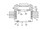
一対の係合枠片29の間で上壁24の前端の中央に薄肉の可撓性のヒンジ30が一体に形成され、ヒンジ30に第二カバー部23が一体に連結されている。第二カバー部23はヒンジ30を支点に開閉方向に回動自在である。第二カバー部23の閉止状態を図2に示している。第二カバー部23は第一カバー部22の上壁24よりも幅広に、且つ第一カバー部22の後壁25と同じ幅で形成されている。
A thin
第二カバー部23は閉止時に上壁となる壁部31と、壁部31の前端に直交して続く前壁となる低い壁部32とを備え、壁部31の後端がヒンジ30で連結され、壁部31の前端寄りにベース6の前端の上向きの位置決め用の突起18に対する左右一対の長方形の係合孔33が設けられ、前側の壁部32にベース6の前端の係止突起19に対する左右一対の矩形状の係合孔34が設けられ、係合孔34の周縁は可撓性を有して略枠状に形成されている。枠状の縁部35の間で前壁32にはアース端子4を進入させる逃がし用の凹部(図示せず)が設けられている。
The
カバー5の裏面(内面)側には、第一カバー部22の内面にはベース6のジョイント部7の各溝部10に対応して電線押圧用のリブ(図示せず)が一体に設けられると共に、リブの長手方向中間部に圧接端子3に対応して切欠部(図示せず)が設けられている。
On the back surface (inner surface) side of the
各リブの左右端は第一カバー部22の左右端において前後方向のリブ39に直交している。左右端のリブ39はベース6の左右の側壁13の内側に進入して、電線9(図4)を半円状の溝部(導出口)14との間で挟持固定する。
The left and right ends of each rib are orthogonal to the front and rear ribs 39 at the left and right ends of the
ベース側のアース端子4は、幅広の基板部41と、基板部41の周囲に立ち上げられた鍔部42と、基板部41に開けられた固定用の孔部43と、基板部41の先端側で下向きに屈曲した舌片部44とを備えている。
The ground terminal 4 on the base side includes a
図2は上記ベース6の縦断面図を示すものであり、アース端子4の基板部41はベース6の電線収束部8の底壁11内で延長され、その延長部45が略コの字状の第一のバスバー46に一体に続いている。第一のバスバー46は前から一列目と三列目の圧接端子31,33に続き、前から二列目と四列目の圧接端子32,34は他の独立した略逆コの字状の第二のバスバー(図示せず)に続いている。
FIG. 2 is a longitudinal sectional view of the
各バスバーは水平な接続板(符号46で代用)と接続板から垂直に立ち上げられた圧接端子3とで構成され、圧接端子3は上端に絶縁被覆切裂刃を有する左右各一対の圧接片3aと圧接片間の電線圧入用のスロット3bとで構成されている。
Each bus bar is composed of a horizontal connecting plate (instead of reference numeral 46) and a
各圧接端子3には各電線(絶縁被覆電線)9が圧接される。第二のバスバーの圧接端子32,34は+極の電線9に接続され、第一のバスバー46の圧接端子31,33は−極の電線9に接続されてアース端子4を介して車両ボディ等のアース側へ接続される。
Each electric wire (insulation coated electric wire) 9 is pressed to each
以下に上記ジョイントボックスの電線収束構造について説明する。 The electric wire convergence structure of the joint box will be described below.
図3の如く、カバー5を外した状態でベース6のジョイント部7の各溝部10に各電線9が配置され、図示しない圧接治具で各電線9が溝部内の各圧接端子3に圧接される。本例で後半の二本の電線(本線)91のうちの一方は+極の第二のバスバー、他方は−極の第一のバスバーに接続され、前半の二本の電線(分岐線)92のうちの一方は+極の第二のバスバー、他方は−極の第一のバスバーに接続され、−極の第一のバスバーはアース端子4に続いている。
As shown in FIG. 3, each wire 9 is disposed in each
電線圧接後に図4の如く、カバー5の第一カバー部22のみがベース6に閉止され、第一カバー部22でジョイント部7が覆われて保護される。前述の如く第一カバー部22の左右端で各電線9がベース6に押圧固定され、電線6の引張力が圧接部(圧接端子3と電線9との接続部)に及ぶことが防止される。第一カバー部22は前後の係止手段21,27、17,29でベース6に係止される。第二カバー部23は開いたままである。
As shown in FIG. 4, only the
第一カバー22を閉止した後に図5,図6の如く、ベース6の電線収束部8内に、圧接しない電線40が真直な状態で配置されると共に、圧接済みの電線9の一部(本例では分岐線92)がU字状に折り返されて配置され、その状態で第二カバー部23が閉止される。第二カバー部23は位置決め手段18,33で位置決めされつつ係止手段19,34でベース6に確実に係止される。電線収束部8内の電線40,92は特に固定されずに挿通されるのみである(長手方向に移動可能で径方向にほぼ不動に固定される)。電線40は種々の太さのものを使用可能である。
After the
このようにして、ジョイントの必要な電線9とその必要のない電線40とが一つのジョイントボックス1内に配索されてカバー5の閉止により収束される。各電線9,40の収束を一つのジョイントボックス1で行うことができるから、従来のハーネスプロテクタが不要となり、部品コストが削減される。
In this way, the electric wires 9 that need joints and the
また、圧接済みの二本の電線(分岐線)92をUターンさせて収束することで、ジョイントボックス内の圧接端子3の数を増やすことなく、四本の電線92の導出方向を一方向(図5で左方向)に統一して、同方向に位置するコネクタ等で接続を集約させることができる。例えば導出された各二本の電線92の端末にはそれぞれコネクタ(図示せず)が配設される。電線(本線)91の端末にもコネクタを配設可能であり、各コネクタは機器やワイヤハーネス等の他のコネクタに接続される。
Further, the pressure already two wires (branch line) 9 2 By converging by U-turn, without increasing the number of press-connecting
圧接接続を行う電線9に関しては、品質等の問題に鑑み、圧接作業を行った場所から圧接した電線9を動かさずに固定してしまうことが理想である。従って、本発明では、先ず電線圧接後に第一カバー部22を直ぐに装着し、ジョイント部7と第一カバー部22とにより電線9を挟んで固定し、圧接端子3にテンションがかからないようにしている。そして、別の工程で他の電線40を電線収束部8に収容し、第二カバー部23を装着している。
With regard to the electric wire 9 that performs the press-contact connection, in view of problems such as quality, it is ideal that the electric wire 9 that is press-contacted from the place where the press-contact operation is performed is fixed without moving. Therefore, in the present invention, the
圧接作業を行った場所で、圧接を行った電線9と、電線収束部8に収容される電線40とをヒンジ30を介さない別体のカバー(図示せず)で一気に覆ってしまうことも可能であるが、慎重な作業を必要とする圧接作業に、圧接に関係ない作業を含めたくないことから、本発明では二つの工程で別々に電線9,40の配索を行っている。このような作業に、本発明のヒンジ30を介して前後のカバー部22,23を連結したカバー5が有効となる。
It is also possible to cover the wire 9 subjected to the pressure welding and the
カバー5でベース6のジョイント部7と電線収束部8とを同時に覆う場合は、電線9をジョイント部7で圧接した後、他の電線40を電線収束部8に挿通させ、カバー5を閉止するか、あるいは、電線9をジョイント部7で圧接した後、圧接済みの電線92をUターンさせて圧接済みの電線92のみを電線収束部8に挿通させて、カバー5を閉止するか、あるいは、電線9をジョイント部7で圧接した後、圧接済みの電線92をUターンさせて他の電線40と共に電線収束部8に挿通させて、カバー5を閉止する。
When simultaneously covering the
これらの場合、カバーは本例のヒンジ付きのカバー5に限らず、一枚の連続した幅広の覆い壁を有するカバー(図示せず)であってもよい。一枚の覆い壁のカバーの場合、電線収束部8の内側の隔壁121に係止手段17を設ける必要はない。
In these cases, the cover is not limited to the hinged
上記実施形態においては、ベース6に対するカバー5の係止手段として係止突起17,19,21と係合枠片29又は係合孔27,34を用いたが、係止手段はこれらに限られるものではなく、例えば係止部としての係止突起や可撓性の係止爪と、係合部としての有底の係合穴(凹部)や係合溝や係合段部等、種々の形態のものを適宜採用可能である。ベース6とカバー5のどちらに係止部を設け、どちらに係合部を設けるかも適宜設定可能である。
In the above embodiment, the locking
また、ジョイント部7と電線収束部8とでカバー5を別々に形成し、これら第一と第二のカバー部22,23をヒンジ30で連結することなく用いるようにすることも可能である。但し、この場合は各カバー部22,23ごとに独立して係止手段を設ける(第二カバー部の後端にも係止枠壁等の係止手段を設ける)必要があり、構造が複雑化、大型化する。
It is also possible to form the
また、上記実施形態においては、本線91と分岐線92を二本ずつ隣接して配置し、第一と第二の各バスバーの各圧接端子3を互い違いになるように配置したが、本線91と分岐線92の配置を一本ずつ互い違いとし、第一のバスバーの各圧接端子3同士を隣接させ、第二のバスバーの各圧接端子3同士を隣接させて配置することも可能である。電線9,40の本数や圧接端子3の数等はジョイント回路形態に応じて適宜設定される。
In the embodiment described above, the main line 9 1 and the branch line 9 2 arranged adjacent one by two, have been arranged such that the first to become staggered second each
また、ベース6からの電線9の導出方向も左右二方向に限らず、左右後の三方向とすることも可能である。この場合、ジョイント部7の後半において左右方向の電線保持溝10に直交して後方に向かう電線保持溝(図示せず)が設けられ、その電線保持溝内にも圧接端子が配設され、例えば電線9が90゜方向に屈曲されて両電線保持溝内に配索されつつ圧接されて右と後又は左と後といった直交方向から導出される。
Further, the lead-out direction of the electric wires 9 from the
また、ジョイント部7において電線9を挟持固定する手段として、カバー側のリブ39に代えて例えばベース側の半割り状の溝14と同様の溝を第一カバー部22の左右端に設けることも可能である。この場合、半割り状の上下の溝14が合体した孔の内径は電線径よりも小さいものとする。
Further, as means for sandwiching and fixing the electric wire 9 in the
また、圧接端子3に代えてバスバーに圧着端子や溶着端子等(図示せず)を一体に又は別体に設けて、圧接に代えて圧着(加締め)や溶接等で電線9の芯線部(導体部)をジョイント接続させることも可能である。圧接端子3や圧着端子や溶着端子等はジョイント用端子と総称することができる。
Further, instead of the
また、アース端子4の形態も平板状に限らずタブ状や雌型状等、種々の形態を適宜設定可能である。 Also, the form of the ground terminal 4 is not limited to a flat form, and various forms such as a tab form and a female form can be appropriately set.
1 ジョイントボックス
3 圧接端子(端子)
4 アース端子
5 カバー
6 ベース
7 ジョイント部
8 電線収束部
9,40 電線
22 第一カバー部
23 第二カバー部
1
Claims (3)
Priority Applications (3)
| Application Number | Priority Date | Filing Date | Title |
|---|---|---|---|
| JP2004150774A JP4317079B2 (en) | 2004-05-20 | 2004-05-20 | Electric wire converging structure of joint box |
| US11/109,770 US7179101B2 (en) | 2004-05-20 | 2005-04-20 | Joint box for connecting electrical wires |
| EP05009721.1A EP1598901B1 (en) | 2004-05-20 | 2005-05-03 | Joint box for connecting electrical wires |
Applications Claiming Priority (1)
| Application Number | Priority Date | Filing Date | Title |
|---|---|---|---|
| JP2004150774A JP4317079B2 (en) | 2004-05-20 | 2004-05-20 | Electric wire converging structure of joint box |
Publications (2)
| Publication Number | Publication Date |
|---|---|
| JP2005332714A JP2005332714A (en) | 2005-12-02 |
| JP4317079B2 true JP4317079B2 (en) | 2009-08-19 |
Family
ID=35487200
Family Applications (1)
| Application Number | Title | Priority Date | Filing Date |
|---|---|---|---|
| JP2004150774A Expired - Fee Related JP4317079B2 (en) | 2004-05-20 | 2004-05-20 | Electric wire converging structure of joint box |
Country Status (1)
| Country | Link |
|---|---|
| JP (1) | JP4317079B2 (en) |
Families Citing this family (5)
| Publication number | Priority date | Publication date | Assignee | Title |
|---|---|---|---|---|
| JP4397862B2 (en) | 2005-07-20 | 2010-01-13 | 矢崎総業株式会社 | Flat cable clamp |
| JP4797588B2 (en) | 2005-11-17 | 2011-10-19 | アイシン精機株式会社 | Vehicle periphery display device |
| JP5652334B2 (en) * | 2011-06-02 | 2015-01-14 | 株式会社オートネットワーク技術研究所 | Joint connector for wire harness |
| JP5413627B2 (en) * | 2012-05-31 | 2014-02-12 | 株式会社葉山電器製作所 | Power supply connector |
| JP7468240B2 (en) | 2020-08-11 | 2024-04-16 | 株式会社明電舎 | Connection reinforcement member, connection reinforcement structure, power conversion device |
Family Cites Families (7)
| Publication number | Priority date | Publication date | Assignee | Title |
|---|---|---|---|---|
| JPH0241819Y2 (en) * | 1984-12-14 | 1990-11-07 | ||
| JPS6284558U (en) * | 1985-11-19 | 1987-05-29 | ||
| JPH0286081U (en) * | 1988-12-22 | 1990-07-06 | ||
| JP3666238B2 (en) * | 1998-04-20 | 2005-06-29 | 住友電装株式会社 | Wire harness protector |
| JP2001155792A (en) * | 1999-11-30 | 2001-06-08 | Fujikura Ltd | ID terminal and connector |
| JP2002010438A (en) * | 2000-06-20 | 2002-01-11 | Sumitomo Wiring Syst Ltd | Protector |
| JP3808375B2 (en) * | 2002-02-06 | 2006-08-09 | 矢崎総業株式会社 | Wire harness protector |
-
2004
- 2004-05-20 JP JP2004150774A patent/JP4317079B2/en not_active Expired - Fee Related
Also Published As
| Publication number | Publication date |
|---|---|
| JP2005332714A (en) | 2005-12-02 |
Similar Documents
| Publication | Publication Date | Title |
|---|---|---|
| US7179101B2 (en) | Joint box for connecting electrical wires | |
| JP3286177B2 (en) | ID connector | |
| JP4246131B2 (en) | Connection structure between electric wire and element built-in unit | |
| JP4317079B2 (en) | Electric wire converging structure of joint box | |
| JP2006107809A (en) | Method and earth connector for grounding and fixing a vehicle wire harness | |
| JP5344900B2 (en) | Terminal connection structure with wires for electrical connection box | |
| CN112018543A (en) | Electric wire with terminal and wire harness | |
| JP2001035556A (en) | Connecting terminal, joint connector using the same and wire harness provided with the joint connector | |
| JP2010103044A (en) | Wire harness including plural short circuits and method for manufacturing the same | |
| JP2019079782A (en) | Branch connector and communication network | |
| JP2008108660A (en) | Wire harness connector | |
| JP2000139016A (en) | Connecting structure of wiring board and manufacture of wiring board assembly | |
| JP4381959B2 (en) | Wire harness joint connector and manufacturing method thereof | |
| JPH08227738A (en) | Connecting structure of electric connection box | |
| JP4324013B2 (en) | Joint box and wiring method using it | |
| JP2007213945A (en) | Wire harness connector | |
| JP2589748Y2 (en) | Joint connector | |
| JP3435009B2 (en) | Electrical junction box | |
| US20040248456A1 (en) | End-processing structure of flat cable and method of end-processing of flat cable | |
| JP3702758B2 (en) | Electrical junction box | |
| JP6927847B2 (en) | Branch connector and communication network | |
| JP2018207710A (en) | Electronic component built-in unit | |
| JP3446689B2 (en) | Branch connection structure of wire harness using joint connector | |
| JP2004055391A (en) | Connector for flat wiring material | |
| JP3246429B2 (en) | Connection structure between wire harness and electrical junction box |
Legal Events
| Date | Code | Title | Description |
|---|---|---|---|
| A621 | Written request for application examination |
Free format text: JAPANESE INTERMEDIATE CODE: A621 Effective date: 20061002 |
|
| A977 | Report on retrieval |
Free format text: JAPANESE INTERMEDIATE CODE: A971007 Effective date: 20081010 |
|
| A131 | Notification of reasons for refusal |
Free format text: JAPANESE INTERMEDIATE CODE: A131 Effective date: 20081021 |
|
| A521 | Request for written amendment filed |
Free format text: JAPANESE INTERMEDIATE CODE: A523 Effective date: 20081218 |
|
| A131 | Notification of reasons for refusal |
Free format text: JAPANESE INTERMEDIATE CODE: A131 Effective date: 20090210 |
|
| A521 | Request for written amendment filed |
Free format text: JAPANESE INTERMEDIATE CODE: A523 Effective date: 20090325 |
|
| TRDD | Decision of grant or rejection written | ||
| A01 | Written decision to grant a patent or to grant a registration (utility model) |
Free format text: JAPANESE INTERMEDIATE CODE: A01 Effective date: 20090512 |
|
| A01 | Written decision to grant a patent or to grant a registration (utility model) |
Free format text: JAPANESE INTERMEDIATE CODE: A01 |
|
| A61 | First payment of annual fees (during grant procedure) |
Free format text: JAPANESE INTERMEDIATE CODE: A61 Effective date: 20090521 |
|
| R150 | Certificate of patent or registration of utility model |
Ref document number: 4317079 Country of ref document: JP Free format text: JAPANESE INTERMEDIATE CODE: R150 Free format text: JAPANESE INTERMEDIATE CODE: R150 |
|
| FPAY | Renewal fee payment (event date is renewal date of database) |
Free format text: PAYMENT UNTIL: 20120529 Year of fee payment: 3 |
|
| FPAY | Renewal fee payment (event date is renewal date of database) |
Free format text: PAYMENT UNTIL: 20130529 Year of fee payment: 4 |
|
| FPAY | Renewal fee payment (event date is renewal date of database) |
Free format text: PAYMENT UNTIL: 20130529 Year of fee payment: 4 |
|
| R250 | Receipt of annual fees |
Free format text: JAPANESE INTERMEDIATE CODE: R250 |
|
| R250 | Receipt of annual fees |
Free format text: JAPANESE INTERMEDIATE CODE: R250 |
|
| R250 | Receipt of annual fees |
Free format text: JAPANESE INTERMEDIATE CODE: R250 |
|
| R250 | Receipt of annual fees |
Free format text: JAPANESE INTERMEDIATE CODE: R250 |
|
| R250 | Receipt of annual fees |
Free format text: JAPANESE INTERMEDIATE CODE: R250 |
|
| R250 | Receipt of annual fees |
Free format text: JAPANESE INTERMEDIATE CODE: R250 |
|
| LAPS | Cancellation because of no payment of annual fees |