JP4280561B2 - Air conditioner - Google Patents
Air conditioner Download PDFInfo
- Publication number
- JP4280561B2 JP4280561B2 JP2003165980A JP2003165980A JP4280561B2 JP 4280561 B2 JP4280561 B2 JP 4280561B2 JP 2003165980 A JP2003165980 A JP 2003165980A JP 2003165980 A JP2003165980 A JP 2003165980A JP 4280561 B2 JP4280561 B2 JP 4280561B2
- Authority
- JP
- Japan
- Prior art keywords
- heat storage
- refrigerant
- valve
- expansion valve
- pipe
- Prior art date
- Legal status (The legal status is an assumption and is not a legal conclusion. Google has not performed a legal analysis and makes no representation as to the accuracy of the status listed.)
- Expired - Fee Related
Links
Images


Landscapes
- Compression-Type Refrigeration Machines With Reversible Cycles (AREA)
Description
【0001】
【発明の属する技術分野】
本発明は、例えば、冷房運転、氷蓄熱運転、氷蓄熱利用冷房運転、暖房運転及び温蓄運転等を可能にした空気調和装置に関する。
【0002】
【従来の技術】
一般に、圧縮機、四方弁、室外熱交換器、室外側膨張弁、蓄熱コイル、室内側膨張弁並びに室内熱交換器を冷媒配管で接続し、前記圧縮機の駆動により、冷房運転、氷蓄熱運転、氷蓄熱利用冷房運転、及び暖房運転等を可能にした空気調和装置が知られている(例えば、特許文献1参照)。
【0003】
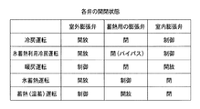
この種のものでは、例えば、電気料金が安価な深夜に、氷蓄熱運転を行い、この蓄熱エネルギを利用して、昼間に氷蓄熱利用冷房運転を行い、昼間の冷房効率を向上させている。ところで、従来の構成では、冷房運転を行う場合、室外側膨張弁を開いた状態で、室内側膨張弁の弁開度を絞る制御を行い、これとは反対に、暖房運転を行う場合、室内側膨張弁を開いた状態で、室外側膨張弁の弁開度を絞る制御が実行される。また、氷蓄熱運転を行う場合には、室内膨張弁を閉じ、室外膨張弁を開放し、蓄熱用の膨張弁の開度制御により冷媒の絞り制御が行われる。この氷蓄熱運転によって生成された氷を利用した氷蓄熱利用冷房運転を行う場合には、室内膨張弁で主に冷媒の絞り制御が行われ、その他の膨張弁で冷媒の流量調整が行われる。除霜運転時の熱源の一部として温水が利用されるが、この温水を蓄熱槽に生成する温蓄運転時には、室内膨張弁を閉じ、蓄熱用の膨張弁を開放し、室外膨張弁の開度制御によって冷媒の絞り制御が行われる。これら膨張弁の開閉制御の関係は、図15に示す通りであるが、いずれの制御であっても、液管内には余剰の液冷媒が滞留し、これを貯留するため、従来、室内外の膨張弁間の液管に受液器が接続されている。
【0004】
【特許文献1】
特開2002−372325号公報
【0005】
【発明が解決しようとする課題】
しかし、従来の構成では、図15に示すように、各運転時に各種の膨張弁の弁開度を個別に制御することになり、この場合、室内側膨張弁と室外側膨張弁の2つの膨張弁が必ず必要になる。そうなると、製造コストが嵩むと共に、膨張弁接続のための配管接続やその制御が面倒になる等の問題がある。
【0006】
そこで、本発明の目的は、上述した従来の技術が有する課題を解消し、いわゆる膨張弁の数を減らし、その制御を簡素化し、かつシンプルな構成の空気調和装置を提供することにある。
【0007】
【課題を解決するための手段】
請求項1記載の発明は、圧縮機、四方弁、室外熱交換器、蓄熱槽に水没状態で配置される蓄熱コイル、室内側膨張弁並びに室内熱交換器を冷媒配管で接続し、前記圧縮機の駆動により、冷房運転、蓄熱槽に氷を生成させる氷蓄熱運転、及び生成した氷を利用した氷蓄熱利用冷房運転を可能にした空気調和装置において、前記室外熱交換器と前記室内熱交換器との間に、少なくとも4つの逆止弁、及びこれら逆止弁の内、2つの逆止弁の組みを連通させるメイン管路を有したブリッジ回路を接続し、このブリッジ回路のメイン管路に受液器とメイン膨張弁とを直列に接続し、冷房運転、氷蓄熱運転、及び氷蓄熱利用冷房運転のいずれの運転中にも、前記メイン管路に接続された受液器、メイン膨張弁の順に冷媒が流れるようにし、前記蓄熱コイルの一端を、解氷弁を介して受液器とメイン膨張弁間のメイン管路に接続し、前記蓄熱コイルの他端を、蓄熱弁を介してブリッジ回路と室内側膨張弁間に接続したことを特徴とする。
【0008】
請求項2記載の発明は、請求項1記載のものにおいて、圧縮機、四方弁、室外熱交換器を室外ユニットに収容し、蓄熱コイル、ブリッジ回路、室内側膨張弁を蓄熱ユニットに収容し、室内熱交換器を室内ユニットに収容し、各ユニット間を冷媒配管で接続したことを特徴とする。
【0009】
請求項3記載の発明は、請求項1又は2記載のものにおいて、前記ブリッジ回路の前記受液器の上部から均圧管を導出し、この均圧管を前記メイン膨張弁の下流に接続したことを特徴とする。
【0011】
請求項4記載の発明は、請求項1乃至3のいずれか一項記載のものにおいて、空気熱源による暖房運転、四方弁の切り換えによって蓄熱槽に温水を生成させる温蓄運転、この温水を利用した除霜運転を可能にしたことを特徴とする。
【0012】
【発明の実施の形態】
以下、本発明の一実施形態を添付した図面を参照して説明する。
【0013】
図1において、100は本実施形態に係る空気調和装置を示し、この空気調和装置100は、室外ユニット10と、蓄熱ユニット20と、室内ユニット30の3つのユニットを備えて構成されている。室外ユニット10は、圧縮機1と、四方弁2と、室外熱交換器3と、アキュームレータ4とを備えて構成される。蓄熱ユニット20は、室外ユニット10に接続されるブリッジ回路40を含んで構成される。このブリッジ回路40は、第1逆止弁41、第2逆止弁42、第3逆止弁43、第4逆止弁44、並びにこれら逆止弁の内、2つの逆止弁の組み(逆止弁41と43、及び逆止弁42と44)を連通させるメイン管路45を含み、このメイン管路45には、受液器46及びメイン膨張弁47が直列に接続されている。また、受液器46の上部からバイパス管路(均圧管)48が導出され、このバイパス管路48には均圧弁49が接続され、この均圧弁49はメイン膨張弁47の下流のメイン管路45に接続されている。
【0014】
蓄熱ユニット20には、蓄熱槽50が含まれる。この蓄熱槽50の中には、蓄熱コイル51が水没状態で配置され、この蓄熱コイル51の一端は、第1管路52、二方弁54を介してガス管60に接続されている。蓄熱コイル51の他端は、第2管路53、蓄熱弁55を介して液管61、すなわちブリッジ回路40と室内側膨張弁21との間の液管61に接続されている。
【0015】
ブリッジ回路40のメイン管路45であって、受液器46とメイン膨張弁47の間のメイン管路45には、第3管路63が接続され、この第3管路63は、解氷弁56、逆止弁57を介して第1管路52、すなわち二方弁54と蓄熱コイル51との間の第1管路52に接続されている。
【0016】
上述のブリッジ回路40には、液管61を介して、室内側膨張弁21が接続され、この室内側膨張弁21には室内ユニット30の室内熱交換器31が接続され、この室内熱交換器31にはガス管60を介して四方弁2が接続されている。なお、室内側膨張弁21は蓄熱ユニット20に含まれる。
【0017】
次に、本実施形態の動作を説明する。
【0018】
図1では、一般的な冷房運転(氷蓄熱未利用冷房運転)時の冷媒の流れを太線で示す。圧縮機1で圧縮された冷媒は、四方弁2を介して室外熱交換器3に流入し、ここで凝縮する。この凝縮した冷媒はブリッジ回路40に入る。このブリッジ回路40では、第1逆止弁41を経てメイン管路45に入り、メイン管路45に接続された受液器46を介してメイン膨張弁47に入る。
【0019】
そして、メイン膨張弁47を経た後、第3逆止弁43を介して液管61に向かい、ここから、室内側膨張弁21を経て、室内ユニット30の室内熱交換器31に流入する。この室内熱交換器31では、冷媒が蒸発して、周囲から蒸発潜熱を奪い、室内を冷房する。そして、室内熱交換器31を経た冷媒は、ガス管60を通り、四方弁2、アキュームレータ4を経て圧縮機1の吸込管に戻される。
【0020】
本実施形態では、夜間の安価な電気を使用して氷蓄熱運転が行われる。この氷蓄熱運転では、図2に太線で示すように冷媒が流される。すなわち、圧縮機1で圧縮された冷媒は、四方弁2、室外熱交換器3を通り、ブリッジ回路40に流入し、このブリッジ回路40の第1逆止弁41を経てメイン管路45に流入する。メイン管路45に流入した冷媒は、受液器46、メイン膨張弁47を経て第3逆止弁43に至り、ここから液管61に流入する。この液管61に流入した冷媒は、蓄熱弁55、第2管路53を通り蓄熱コイル51に流入し、ここで蒸発し蓄熱槽50内に製氷する。
【0021】
蓄熱槽50内に製氷させた冷媒は、第1管路52、二方弁54を通りガス管60に流入し、更に、四方弁2、アキュームレータ4を経て圧縮機1に戻される。
【0022】
冷房運転には、図1に示す氷蓄熱未利用冷房運転の他に、図2に示す製氷を利用した、氷蓄熱利用冷房運転が含まれる。
【0023】
この利用冷房運転では、図3に示すように、冷媒制御が行われる。すなわち、圧縮機1で圧縮された冷媒は四方弁2、室外熱交換器3を経て、ブリッジ回路40に流入し、このブリッジ回路40の第1逆止弁41、メイン管路45、受液器46を経て、一方は第3管路63に流入し、他方はそのままメイン管路45を流れてメイン膨張弁47に至る。
【0024】
第3管路63に流入した冷媒は、解氷弁56、逆止弁57を経て蓄熱槽50内の蓄熱コイル51に入る。この冷媒は、蓄熱コイル51内で氷により過冷却され、その後に、第2管路53を経て蓄熱弁55を通り液管61に流入する。また、ブリッジ回路40の受液器46を経て、そのままメイン膨張弁47に流入した冷媒は、第3逆止弁43を通り液管61に流入する。
【0025】
この液管61では、蓄熱コイル51を経て過冷却された冷媒と、メイン膨張弁47を経た冷媒とが合流し、この合流した冷媒は、室内側膨張弁21を通り、室内ユニット30の室内熱交換器31に流入する。この室内熱交換器31では、冷媒が蒸発し、これにより室内が冷房される。そして、室内熱交換器31を経た冷媒は、ガス管60を通り、四方弁2、アキュームレータ4を経て、圧縮機1の吸込管に戻される。
【0026】
この場合、本実施形態では、冷媒が蓄熱槽50で過冷却された分だけ、冷房効率を向上させることができる。
【0027】
上記構成では暖房運転が可能である。この暖房運転では、図4に示すように、冷媒の流れが制御される。
【0028】
すなわち、圧縮機1に吐出された冷媒は、四方弁2を通りガス管60に流入し、このガス管60を経て室内ユニット30の室内熱交換器31に流入し、この室内熱交換器31で凝縮し、これにより、室内が暖房される。この室内熱交換器31を経た冷媒は、室内側膨張弁21を通り、液管61に流入し、更にブリッジ回路40に流入する。このブリッジ回路40に入ると、冷媒は、第2逆止弁42を経てメイン管路45に流入し、受液器46、メイン膨張弁47を経て第4逆止弁44に至り、この第4逆止弁44を通過して、室外ユニット10の室外熱交換器3に流入する。この室外熱交換器3では、冷媒が蒸発し、これによりガス化された冷媒が、四方弁2、アキュームレータ4を経て圧縮機1に戻される。
【0029】
この暖房運転が、厳冬期等の著しい低外気温の状態下で行われた場合、室外熱交換器3のフィンに着霜する。この室外熱交換器3の着霜を除去するため、除霜運転が行われる。
【0030】
図5は、空気除霜運転を示す。この除霜運転では、暖房運転を一時的に停止し、四方弁2を冷房位置に切り換え、圧縮機1を駆動する。すると、図5に示すように、圧縮機1で圧縮された冷媒が、四方弁2を経て、室外熱交換器3に直接流入し、ここに直接流入したホットガスにより室外熱交換器3が除霜される。この室外熱交換器3を経た冷媒は、図1に示す冷房運転の場合とほぼ同様の流れを経て圧縮機1に戻される。
【0031】
図6は、蓄熱槽に温水を生成する温蓄運転を示す。この温蓄運転では、蓄熱槽50内の水の温度を上昇させる。この温蓄運転では、圧縮機1で圧縮された冷媒が、四方弁2を通り、ガス管60に流入し、このガス管60から二方弁54、第1管路52を経て、蓄熱コイル51に流入する。冷媒は、この蓄熱コイル51で凝縮し、蓄熱槽50内の水温を上昇させる。この蓄熱コイル51を経た冷媒は、第2管路53、蓄熱弁55を通りブリッジ回路40に流入し、このブリッジ回路40に流入した冷媒は、第2逆止弁42を通りメイン管路45に入り、受液器46、メイン膨張弁47を経て第4逆止弁44に至る。
【0032】
そして、第4逆止弁44を経て室外ユニット10の室外熱交換器3に至り、ここで蒸発し、ガス化した冷媒が、四方弁2、アキュームレータ4を経て圧縮機1に戻される。
【0033】
この温蓄運転によって、蓄熱槽50内に温蓄されたエネルギは、図7に示すように、専ら温水除霜運転に利用される。
【0034】
すなわち、圧縮機1で圧縮された冷媒は、四方弁2を経て、室外熱交換器3に流入し、この室外熱交換器3で凝縮し、この室外熱交換器3のフィンに付着した霜を除去する。室外熱交換器3を経た冷媒は、ブリッジ回路40に入り、このブリッジ回路40の第1逆止弁41、メイン管路45、受液器46、メイン膨張弁47を経て第3逆止弁43に至り、ここから蓄熱弁55、第2管路53を通り、蓄熱コイル51に流入する。
【0035】
この蓄熱コイル51では、冷媒が、蓄熱槽50内の温蓄エネルギから熱を奪い、いわゆる冷媒加熱されて第1管路52を経て二方弁54に至る。そして、二方弁54からガス管60に入り、四方弁2、アキュームレータ4を経て圧縮機1に戻される。
【0036】
この温水利用による除霜運転では、蓄熱槽50内で冷媒が加熱されて圧縮機1に戻されるため、除霜運転の効率が向上し、除霜運転を、図5の除霜運転に比べて短時間のうちに終了させることができる。
【0037】
本実施形態では、図1〜図7に示すように、いかなる運転モードにおいてもブリッジ回路40のメイン管路45を通る冷媒は、まず、受液器46に入り、それを経てからメイン膨張弁47に至る。従って、冷房運転時、或いは暖房運転時において、弁開度を制御すべき膨張弁は、主にこの一つのメイン膨張弁47だけである。なお、氷蓄熱利用冷房運転時には、メイン膨張弁47において、冷媒流量の補助調整が行われる。蓄熱槽50を有した空気調和装置100では、その冷凍サイクル内への冷媒充填量は多い。従って、いずれの運転時であっても、メイン膨張弁47の弁開度を絞ることにより、液管61内には余剰の液冷媒が滞留する。この余剰の冷媒は、メイン膨張弁47の上流に位置する受液器46に貯留される。
【0038】
上記構成では、従来のように、冷房運転を行う場合、室外側膨張弁を開いた状態で、室内側膨張弁の弁開度を絞る制御を行い、これとは反対に、暖房運転を行う場合、室内側膨張弁を開いた状態で、室外側膨張弁の弁開度を絞る制御、等が不要になり、その結果、従来の構成では、少なくとも2個必要であった膨張弁を、1つのメイン膨張弁47で構成することが可能になり、膨張弁の個数を削減でき、コストダウンが図られる。なお、氷蓄熱利用冷房運転時は、2つの膨張弁によって減圧、並びに流量調整が行われる。
【0039】
上記構成では、ブリッジ回路40の受液器46の上部から均圧管48が導出され、この均圧管48がメイン膨張弁47の下流に接続される。一般に、空気調和装置100の運転停止時に、このメイン膨張弁47を境に、その前後に低圧のガス冷媒領域と高圧の液冷媒領域とが形成される。従来、膨張弁を開放して各領域を均圧したが、これだと、圧縮機1の再起動時に、大量の液冷媒が低圧ガス冷媒領域に流入して、圧縮機1への液バックを起こす。従来、アキュームレータ4の容量は大容量(例えば、7.5リットル)としている。
【0040】
圧縮機1への液バックを解消するため、上記構成では、空気調和装置100の運転停止時に、メイン膨張弁47が閉じられ、均圧管48の均圧弁49が開放される。これにより均圧管48を経て、メイン膨張弁47の前後の管が連通し、当該メイン膨張弁47の前後の圧力が均圧される。
【0041】
この場合、受液器46の上部にはガス冷媒が滞留するため、均圧管48の均圧弁49が開放されたとしても、均圧管48を経て移動するのはガス冷媒であり、液冷媒の移動はない。この場合、アキュームレータ4の容量は小容量(例えば、2.5リットル)とすることができ、このアキュームレータ4の容量は、いわゆる汎用室外ユニットのものと同じである。
【0042】
上記構成では、メイン膨張弁47をブリッジ回路40に組み込み、このブリッジ回路40を蓄熱ユニット20に収容すると共に、この蓄熱ユニット20には、室内膨張弁21を収容したため、室外ユニット10、並びに室内ユニット30には、膨張弁を収容する必要がない。また、室外ユニット10内のアキュームレータ4の容量は、上述したように、汎用ユニット同様に小容量(例えば、2.5リットル)である。従って、空気調和装置100の室外ユニット10として、膨張弁を内蔵しない従来の汎用室外ユニットを、空気調和装置100の蓄熱ユニット20と組み合わせて使用することが可能になる。
【0043】
図8〜図14は別の実施形態を示す。図8〜図14は、それぞれ図1〜図7に対応した冷媒回路図である。図8において、図1に示す実施形態と異なる点は、蓄熱槽50周辺における配管系にある。
【0044】
この蓄熱槽50の中に水没した蓄熱コイル51は、その一端が、第1管路52、二方弁54を介してガス管60に接続されると共に、同じく第1管路52、サブクール弁71、逆止弁72を介して液管61に接続される。蓄熱コイル51の他端は、第2管路53、蓄熱弁55を介して液管61、すなわちブリッジ回路40と室内側膨張弁21との間の液管61に接続されている。ブリッジ回路40のメイン管路45であって、受液器46とメイン膨張弁47の間のメイン管路45には、第3管路63が接続され、この第3管路63は、解氷弁56、逆止弁57を介して、上述した蓄熱コイル51の他端に接続されている。その他の構成は、図1に示すものとほぼ同じ構成である。
【0045】
次に、本実施形態の動作を説明する。
【0046】
図8では、一般的な冷房運転(氷蓄熱未利用冷房運転)時の冷媒の流れを太線で示す。圧縮機1で圧縮された冷媒は、四方弁2を介して室外熱交換器3に流入し、ここで凝縮する。この凝縮した冷媒はブリッジ回路40に入る。このブリッジ回路40では、第1逆止弁41を経てメイン管路45に入り、メイン管路45に接続された受液器46を介してメイン膨張弁47に入る。
【0047】
そして、メイン膨張弁47を経た後、第3逆止弁43を介して液管61に向かい、ここから、室内側膨張弁21を経て、室内ユニット30の室内熱交換器31に流入する。この室内熱交換器31では、冷媒が蒸発して、周囲から蒸発潜熱を奪い、室内を冷房する。そして、室内熱交換器31を経た冷媒は、ガス管60を通り、四方弁2、アキュームレータ4を経て圧縮機1の吸込管に戻される。
【0048】
本実施形態では、夜間の安価な電気を使用して氷蓄熱運転が行われる。この氷蓄熱運転では、図9に太線で示すように冷媒が流される。すなわち、圧縮機1で圧縮された冷媒は、四方弁2、室外熱交換器3を通り、ブリッジ回路40に流入し、このブリッジ回路40の第1逆止弁41を経てメイン管路45に流入する。メイン管路45に流入した冷媒は、受液器46、メイン膨張弁47を経て第3逆止弁43に至り、ここから液管61に流入する。
【0049】
この液管61に流入した冷媒は、蓄熱弁55、第2管路53を通り蓄熱コイル51に流入し、ここで蒸発し蓄熱槽50内に製氷する。この場合、サブクール弁71は全閉である。この氷蓄熱運転時における蓄熱コイル51内の冷媒の流れは、矢印X方向である。
【0050】
蓄熱槽50内に製氷させた冷媒は、第1管路52、二方弁54を通りガス管60に流入し、更に、四方弁2、アキュームレータ4を経て圧縮機1に戻される。
【0051】
冷房運転には、図8に示す氷蓄熱未利用冷房運転の他に、図9に示す製氷を利用した、氷蓄熱利用冷房運転が含まれる。
【0052】
この利用冷房運転では、図10に示すように、冷媒制御が行われる。すなわち、圧縮機1で圧縮された冷媒は四方弁2、室外熱交換器3を経て、ブリッジ回路40に流入し、このブリッジ回路40の第1逆止弁41、メイン管路45、受液器46を経て、一方は第3管路63に流入し、他方はそのままメイン管路45を流れてメイン膨張弁47に至る。
【0053】
第3管路63に流入した冷媒は、解氷弁56、逆止弁57を経て蓄熱槽50内の蓄熱コイル51に入る。この氷蓄熱利用冷房運転時における蓄熱コイル51内の冷媒の流れは、矢印X方向である。
【0054】
この冷媒は、蓄熱コイル51内で氷により過冷却され、その後に、第1管路52、サブクール弁71、逆止弁72を通り液管61に流入する。また、ブリッジ回路40の受液器46を経て、そのままメイン膨張弁47に流入した冷媒は、第3逆止弁43を通り液管61に流入する。
【0055】
この液管61では、蓄熱コイル51を経て過冷却された冷媒と、メイン膨張弁47を経た冷媒とが合流し、この合流した冷媒は、室内側膨張弁21を通り、室内ユニット30の室内熱交換器31に流入する。この室内熱交換器31では、冷媒が蒸発し、これにより室内が冷房される。そして、室内熱交換器31を経た冷媒は、ガス管60を通り、四方弁2、アキュームレータ4を経て、圧縮機1の吸込管に戻される。この氷蓄熱利用冷房運転時には室内側膨張弁21で冷媒の膨張作用を行わせ、メイン膨張弁47で冷媒の流れ調整を行う。
【0056】
この場合、本実施形態では、冷媒が蓄熱槽50で過冷却された分だけ、冷房効率を向上させることができる。
【0057】
上記構成では暖房運転が可能である。この暖房運転では、図11に示すように、冷媒の流れが制御される。
【0058】
すなわち、圧縮機1に吐出された冷媒は、四方弁2を通りガス管60に流入し、このガス管60を経て室内ユニット30の室内熱交換器31に流入し、この室内熱交換器31で凝縮し、これにより、室内が暖房される。この室内熱交換器31を経た冷媒は、室内側膨張弁21を通り、液管61に流入し、更にブリッジ回路40に流入する。このブリッジ回路40に入ると、冷媒は、第2逆止弁42を経てメイン管路45に流入し、受液器46、メイン膨張弁47を経て第4逆止弁44に至り、この第4逆止弁44を通過して、室外ユニット10の室外熱交換器3に流入する。この室外熱交換器3では、冷媒が蒸発し、これによりガス化された冷媒が、四方弁2、アキュームレータ4、サブアキュームレータ5を経て圧縮機1に戻される。
【0059】
この暖房運転が、厳冬期等の著しい低外気温の状態下で行われた場合、室外熱交換器3のフィンに着霜する。この室外熱交換器3の着霜を除去するため、除霜運転が行われる。
【0060】
図12は、空気除霜運転を示す。この除霜運転では、暖房運転を一時的に停止し、四方弁2を冷房位置に切り換え、圧縮機1を駆動する。すると、図12に示すように、圧縮機1で圧縮された冷媒が、四方弁2を経て、室外熱交換器3に直接流入し、ここに直接流入したホットガスにより室外熱交換器3が除霜される。この室外熱交換器3を経た冷媒は、図8に示す冷房運転の場合とほぼ同様の流れを経て圧縮機1に戻される。
【0061】
この場合、室内熱交換器31の送風ファンの運転は停止し、冷媒を蒸発させない。本来の要求は暖房運転であり、除霜運転時に室内に冷風が吹き出されないようにするためである。
【0062】
図13は、温蓄運転を示す。この温蓄運転では、蓄熱槽50内の水の温度を上昇させる。この温蓄運転では、圧縮機1で圧縮された冷媒が、四方弁2を通り、ガス管60に流入し、このガス管60から二方弁54、第1管路52を経て、蓄熱コイル51に流入する。冷媒は、この蓄熱コイル51で凝縮し、蓄熱槽50内の水温を上昇させる。この蓄熱コイル51を経た冷媒は、第2管路53、蓄熱弁55を通りブリッジ回路40に流入し、このブリッジ回路40に流入した冷媒は、第2逆止弁42を通りメイン管路45に入り、受液器46、メイン膨張弁47を経て第4逆止弁44に至る。
【0063】
そして、第4逆止弁44を経て室外ユニット10の室外熱交換器3に至り、ここで蒸発し、ガス化した冷媒が、四方弁2、アキュームレータ4を経て圧縮機1に戻される。
【0064】
この温蓄運転によって、蓄熱槽50内に温蓄されたエネルギは、図14に示すように、専ら温水除霜運転に利用される。
【0065】
すなわち、圧縮機1で圧縮された冷媒は、四方弁2を経て、室外熱交換器3に流入し、この室外熱交換器3で凝縮し、この室外熱交換器3のフィンに付着した霜を除去する。室外熱交換器3を経た冷媒は、ブリッジ回路40に入り、このブリッジ回路40の第1逆止弁41、メイン管路45、受液器46、メイン膨張弁47を経て第3逆止弁43に至り、ここから蓄熱弁55、第2管路53を通り、蓄熱コイル51に流入する。
【0066】
この蓄熱コイル51では、冷媒が、蓄熱槽50内の温蓄エネルギから熱を奪い、いわゆる冷媒加熱されて第1管路52を経て二方弁54に至る。そして、二方弁54からガス管60に入り、四方弁2、アキュームレータ4を経て圧縮機1に戻される。
【0067】
この温水利用による除霜運転では、蓄熱槽50内で冷媒が加熱されて圧縮機1に戻されるため、除霜運転の効率が向上し、除霜運転を、図12の除霜運転に比べて短時間のうちに終了させることができる。
【0068】
本実施形態では、図8〜図14に示すように、いかなる運転モードにおいてもブリッジ回路40のメイン管路45を通る冷媒は、まず、受液器46に入り、それを経てからメイン膨張弁47に至る。従って、冷房運転時、或いは暖房運転時において、弁開度を制御すべき膨張弁はこの一つのメイン膨張弁47である。いずれの運転時であっても、メイン膨張弁47の弁開度を絞ることにより、液管61内には余剰の液冷媒が滞留する。この余剰の冷媒は、メイン膨張弁47の上流に位置する受液器46に貯留される。
【0069】
上記構成では、従来のように、冷房運転を行う場合、室外側膨張弁を開いた状態で、室内側膨張弁の弁開度を絞る制御を行い、これとは反対に、暖房運転を行う場合、室内側膨張弁を開いた状態で、室外側膨張弁の弁開度を絞る制御、等が不要になり、その結果、従来の構成では、少なくとも2個必要であった膨張弁を、1つのメイン膨張弁47で構成することが可能になり、膨張弁の個数を削減でき、コストダウンが図られる。
【0070】
上記構成では、ブリッジ回路40の受液器46の上部から均圧管48が導出され、この均圧管48がメイン膨張弁47の下流に接続される。一般に、空気調和装置100の運転停止時に、このメイン膨張弁47を境に、その前後に低圧のガス冷媒領域と高圧の液冷媒領域とが形成される。従来、膨張弁を開放して各領域を均圧したが、これだと、圧縮機1の再起動時に、大量の液冷媒が低圧ガス冷媒領域に流入して、圧縮機1への液バックを起こす。従来、アキュームレータ4の容量は大容量(例えば、7.5リットル)としている。
【0071】
圧縮機1への液バックを解消するため、上記構成では、空気調和装置100の運転停止時に、メイン膨張弁47が閉じられ、均圧管48の均圧弁49が開放される。これにより均圧管48を経て、メイン膨張弁47の前後の管が連通し、当該メイン膨張弁47の前後の圧力が均圧される。
【0072】
この場合、受液器46の上部にはガス冷媒が滞留するため、均圧管48の均圧弁49が開放されたとしても、均圧管48を経て移動するのはガス冷媒であり、液冷媒の移動はない。この場合、アキュームレータ4の容量は小容量(例えば、2.5リットル)とすることができ、このアキュームレータ4の容量は、いわゆる汎用室外ユニットのものと同じである。
【0073】
上記構成では、メイン膨張弁47をブリッジ回路40に組み込み、このブリッジ回路40を蓄熱ユニット20に収容すると共に、この蓄熱ユニット20には、室内膨張弁21を収容したため、室外ユニット10、並びに室内ユニット30には、膨張弁を収容する必要がない。また、室外ユニット10内のアキュームレータ4の容量は、上述したように、汎用ユニット同様に小容量(例えば、2.5リットル)である。従って、空気調和装置100の室外ユニット10として、膨張弁を内蔵しない従来の汎用室外ユニットを、空気調和装置100の蓄熱ユニット20と組み合わせて使用することが可能になる。
【0074】
以上、一実施形態に基づいて本発明を説明したが、本発明は、これに限定されるものではない。例えば、空気調和装置100を、室外ユニット10、蓄熱ユニット20、及び室内ユニット30の3つのユニットで構成したが、これに限定されるものではなく、室外ユニット10及び蓄熱ユニット20を一体化させることは可能である。
【0075】
【発明の効果】
本発明では、膨張弁の数が減らされ、その制御が簡素化され、かつシンプルな構成の空気調和装置が提供される。
【図面の簡単な説明】
【図1】本発明の一実施形態を示す氷蓄熱未利用冷房運転時の冷媒回路図である。
【図2】本発明の一実施形態を示す氷蓄熱運転時の冷媒回路図である。
【図3】本発明の一実施形態を示す氷蓄熱利用冷房運転時の冷媒回路図である。
【図4】本発明の一実施形態を示す暖房運転時の冷媒回路図である。
【図5】本発明の一実施形態を示す空気除霜運転時の冷媒回路図である。
【図6】本発明の一実施形態を示す温蓄運転時の冷媒回路図である。
【図7】本発明の一実施形態を示す温水除霜運転時の冷媒回路図である。
【図8】本発明の他の実施形態を示す氷蓄熱未利用冷房運転時の冷媒回路図である。
【図9】本発明の他の実施形態を示す氷蓄熱運転時の冷媒回路図である。
【図10】本発明の他の実施形態を示す氷蓄熱利用冷房運転時の冷媒回路図である。
【図11】本発明の他の実施形態を示す暖房運転時の冷媒回路図である。
【図12】本発明の他の実施形態を示す空気除霜運転時の冷媒回路図である。
【図13】本発明の他の実施形態を示す温蓄運転時の冷媒回路図である。
【図14】本発明の他の実施形態を示す温水除霜運転時の冷媒回路図である。
【図15】各弁の開閉状態を示す図である。
【符号の説明】
1 圧縮機
2 四方弁
3 室外熱交換器
10 室外ユニット
20 蓄熱ユニット
30 室内ユニット
31 室内熱交換器
21 室内側膨張弁
40 ブリッジ回路
41〜44 第1〜第4逆止弁
45 メイン管路
46 受液器
47 メイン膨張弁
48 均圧管(バイパス管路)
49 均圧弁
50 蓄熱槽
51 蓄熱コイル
54 二方弁
55 蓄熱弁
56 解氷弁
60 ガス管
61 液管
71 サブクール弁[0001]
BACKGROUND OF THE INVENTION
The present invention relates to an air conditioner that enables, for example, cooling operation, ice heat storage operation, ice heat storage cooling operation, heating operation, and heat storage operation.
[0002]
[Prior art]
Generally, a compressor, a four-way valve, an outdoor heat exchanger, an outdoor expansion valve, a heat storage coil, an indoor expansion valve and an indoor heat exchanger are connected by a refrigerant pipe, and cooling operation and ice heat storage operation are performed by driving the compressor. In addition, an air conditioner that enables cooling operation using ice heat storage, heating operation, and the like is known (see, for example, Patent Document 1).
[0003]
In this type, for example, ice storage operation is performed in the middle of the night when the electricity rate is low, and this heat storage energy is used to perform cooling operation using ice storage in the daytime to improve daytime cooling efficiency. By the way, in the conventional configuration, when performing the cooling operation, control is performed to reduce the valve opening degree of the indoor expansion valve while the outdoor expansion valve is opened, and on the contrary, when performing the heating operation, In a state where the inner expansion valve is opened, control for reducing the valve opening degree of the outdoor expansion valve is executed. When performing the ice heat storage operation, the indoor expansion valve is closed, the outdoor expansion valve is opened, and the throttle control of the refrigerant is performed by controlling the opening degree of the heat storage expansion valve. When performing an ice heat storage cooling operation using ice generated by the ice heat storage operation, the refrigerant expansion control is mainly performed by the indoor expansion valve, and the refrigerant flow rate is adjusted by the other expansion valves. Hot water is used as part of the heat source during the defrosting operation. During the heat storage operation that generates this hot water in the heat storage tank, the indoor expansion valve is closed, the heat storage expansion valve is opened, and the outdoor expansion valve is opened. The throttle control of the refrigerant is performed by the degree control. The relationship of the expansion valve opening / closing control is as shown in FIG. 15. However, in any control, excessive liquid refrigerant stays in the liquid pipe and is stored. A liquid receiver is connected to the liquid pipe between the expansion valves.
[0004]
[Patent Document 1]
Japanese Patent Laid-Open No. 2002-372325
[Problems to be solved by the invention]
However, in the conventional configuration, as shown in FIG. 15, the valve openings of various expansion valves are individually controlled during each operation, and in this case, two expansions of the indoor expansion valve and the outdoor expansion valve are performed. A valve is absolutely necessary. If it becomes so, while manufacturing cost will increase, there exist problems, such as piping connection for an expansion valve connection, and the control that become troublesome.
[0006]
SUMMARY OF THE INVENTION An object of the present invention is to solve the above-described problems of the prior art, reduce the number of so-called expansion valves, simplify the control, and provide an air conditioner having a simple configuration.
[0007]
[Means for Solving the Problems]
According to the first aspect of the present invention, a compressor, a four-way valve, an outdoor heat exchanger, a heat storage coil disposed in a submerged state in a heat storage tank, an indoor expansion valve, and an indoor heat exchanger are connected by refrigerant piping, and the compressor The outdoor heat exchanger and the indoor heat exchanger in the air conditioner that enabled cooling operation, ice heat storage operation for generating ice in the heat storage tank, and ice storage heat-use cooling operation using the generated ice A bridge circuit having a main line for communicating at least four check valves and a set of two check valves among the check valves, and connected to the main line of the bridge circuit The liquid receiver and the main expansion valve are connected in series, and the liquid receiver and the main expansion valve are connected to the main pipe line during any of the cooling operation, the ice heat storage operation, and the ice heat storage cooling operation. as the refrigerant flows in the order of, the heat storage carp One end of, and connected to the main conduit between the receiver and the main expansion valve via the Kaikoriben, the other end of the thermal storage coil, connected between the bridge circuit and the indoor expansion valve via the heat storage valve It is characterized by that.
[0008]
The invention according to
[0009]
According to a third aspect of the present invention, in the first or second aspect of the invention, a pressure equalizing pipe is led out from an upper part of the liquid receiver of the bridge circuit, and the pressure equalizing pipe is connected downstream of the main expansion valve. Features.
[0011]
The invention of claim 4, wherein, in one of any one of claims 1 to 3, the heating operation by the air heat source, Yutaka蓄operation for producing hot water in the thermal storage tank by switching the four-way valve, utilizing this warm water The defrosting operation is made possible.
[0012]
DETAILED DESCRIPTION OF THE INVENTION
Hereinafter, an embodiment of the present invention will be described with reference to the accompanying drawings.
[0013]
In FIG. 1,
[0014]
The
[0015]
A
[0016]
The
[0017]
Next, the operation of this embodiment will be described.
[0018]
In FIG. 1, the flow of the refrigerant at the time of general cooling operation (cooling operation not using ice heat storage) is indicated by a thick line. The refrigerant compressed by the compressor 1 flows into the
[0019]
Then, after passing through the
[0020]
In this embodiment, the ice heat storage operation is performed using inexpensive electricity at night. In this ice heat storage operation, the refrigerant flows as shown by a thick line in FIG. That is, the refrigerant compressed by the compressor 1 flows into the
[0021]
The refrigerant made into ice in the
[0022]
The cooling operation includes an ice storage utilization cooling operation using ice making shown in FIG. 2 in addition to the ice storage non-use cooling operation shown in FIG.
[0023]
In this use cooling operation, refrigerant control is performed as shown in FIG. That is, the refrigerant compressed by the compressor 1 flows into the
[0024]
The refrigerant flowing into the
[0025]
In the
[0026]
In this case, in this embodiment, the cooling efficiency can be improved by the amount that the refrigerant is supercooled in the
[0027]
In the above configuration, heating operation is possible. In this heating operation, the flow of the refrigerant is controlled as shown in FIG.
[0028]
That is, the refrigerant discharged to the compressor 1 flows into the
[0029]
When this heating operation is performed under conditions of extremely low outside air temperature such as during the severe winter season, the fins of the
[0030]
FIG. 5 shows the air defrosting operation. In this defrosting operation, the heating operation is temporarily stopped, the four-
[0031]
FIG. 6 shows a heat storage operation for generating hot water in the heat storage tank. In this heat storage operation, the temperature of the water in the
[0032]
Then, the refrigerant reaches the
[0033]
The energy stored in the
[0034]
That is, the refrigerant compressed by the compressor 1 flows into the
[0035]
In the
[0036]
In this defrosting operation using hot water, since the refrigerant is heated in the
[0037]
In this embodiment, as shown in FIGS. 1 to 7, the refrigerant passing through the
[0038]
In the above configuration, when performing the cooling operation as in the conventional case, when the outdoor expansion valve is opened, the valve opening degree of the indoor expansion valve is controlled, and on the contrary, the heating operation is performed. In the state where the indoor expansion valve is opened, control for reducing the valve opening degree of the outdoor expansion valve, etc. becomes unnecessary. As a result, in the conventional configuration, at least two expansion valves are required. The
[0039]
In the above configuration, the
[0040]
In order to eliminate the liquid back to the compressor 1, in the above configuration, when the operation of the
[0041]
In this case, since the gas refrigerant stays in the upper part of the
[0042]
In the above configuration, the
[0043]
8-14 show another embodiment. 8 to 14 are refrigerant circuit diagrams corresponding to FIGS. 1 to 7, respectively. 8 is different from the embodiment shown in FIG. 1 in the piping system around the
[0044]
One end of the
[0045]
Next, the operation of this embodiment will be described.
[0046]
In FIG. 8, the flow of the refrigerant at the time of general cooling operation (cooling operation not using ice heat storage) is indicated by a thick line. The refrigerant compressed by the compressor 1 flows into the
[0047]
Then, after passing through the
[0048]
In this embodiment, the ice heat storage operation is performed using inexpensive electricity at night. In this ice heat storage operation, the refrigerant flows as shown by the thick line in FIG. That is, the refrigerant compressed by the compressor 1 flows into the
[0049]
The refrigerant that has flowed into the
[0050]
The refrigerant made into ice in the
[0051]
The cooling operation includes an ice storage-use cooling operation using ice making as shown in FIG. 9 in addition to the ice storage non-use cooling operation shown in FIG.
[0052]
In this cooling use operation, refrigerant control is performed as shown in FIG. That is, the refrigerant compressed by the compressor 1 flows into the
[0053]
The refrigerant flowing into the
[0054]
This refrigerant is supercooled by ice in the
[0055]
In the
[0056]
In this case, in this embodiment, the cooling efficiency can be improved by the amount that the refrigerant is supercooled in the
[0057]
In the above configuration, heating operation is possible. In this heating operation, the flow of the refrigerant is controlled as shown in FIG.
[0058]
That is, the refrigerant discharged to the compressor 1 flows into the
[0059]
When this heating operation is performed under conditions of extremely low outside air temperature such as during the severe winter season, the fins of the
[0060]
FIG. 12 shows the air defrosting operation. In this defrosting operation, the heating operation is temporarily stopped, the four-
[0061]
In this case, the operation of the blower fan of the
[0062]
FIG. 13 shows a heat storage operation. In this heat storage operation, the temperature of the water in the
[0063]
Then, the refrigerant reaches the
[0064]
The energy stored in the
[0065]
That is, the refrigerant compressed by the compressor 1 flows into the
[0066]
In the
[0067]
In this defrosting operation using hot water, since the refrigerant is heated in the
[0068]
In this embodiment, as shown in FIGS. 8 to 14, the refrigerant passing through the
[0069]
In the above configuration, when performing the cooling operation as in the conventional case, when the outdoor expansion valve is opened, the valve opening degree of the indoor expansion valve is controlled, and on the contrary, the heating operation is performed. In the state where the indoor expansion valve is opened, control for reducing the valve opening degree of the outdoor expansion valve, etc. becomes unnecessary. As a result, in the conventional configuration, at least two expansion valves are required. The
[0070]
In the above configuration, the
[0071]
In order to eliminate the liquid back to the compressor 1, in the above configuration, when the operation of the
[0072]
In this case, since the gas refrigerant stays in the upper part of the
[0073]
In the above configuration, the
[0074]
As mentioned above, although this invention was demonstrated based on one Embodiment, this invention is not limited to this. For example, although the
[0075]
【The invention's effect】
In the present invention, the number of expansion valves is reduced, the control thereof is simplified, and an air conditioner having a simple configuration is provided.
[Brief description of the drawings]
FIG. 1 is a refrigerant circuit diagram during an ice storage non-use cooling operation showing an embodiment of the present invention.
FIG. 2 is a refrigerant circuit diagram at the time of ice heat storage operation showing an embodiment of the present invention.
FIG. 3 is a refrigerant circuit diagram at the time of cooling operation using ice heat storage according to an embodiment of the present invention.
FIG. 4 is a refrigerant circuit diagram during heating operation showing an embodiment of the present invention.
FIG. 5 is a refrigerant circuit diagram during an air defrosting operation showing an embodiment of the present invention.
FIG. 6 is a refrigerant circuit diagram during a heat storage operation showing an embodiment of the present invention.
FIG. 7 is a refrigerant circuit diagram at the time of hot water defrosting operation showing an embodiment of the present invention.
FIG. 8 is a refrigerant circuit diagram at the time of cooling operation not using ice storage and showing another embodiment of the present invention.
FIG. 9 is a refrigerant circuit diagram during ice heat storage operation showing another embodiment of the present invention.
FIG. 10 is a refrigerant circuit diagram at the time of cooling operation using ice heat storage according to another embodiment of the present invention.
FIG. 11 is a refrigerant circuit diagram during heating operation showing another embodiment of the present invention.
FIG. 12 is a refrigerant circuit diagram during an air defrosting operation showing another embodiment of the present invention.
FIG. 13 is a refrigerant circuit diagram during a heat storage operation showing another embodiment of the present invention.
FIG. 14 is a refrigerant circuit diagram at the time of hot water defrosting operation showing another embodiment of the present invention.
FIG. 15 is a diagram showing an open / close state of each valve.
[Explanation of symbols]
DESCRIPTION OF SYMBOLS 1
49
Claims (4)
前記蓄熱コイルの一端を、解氷弁を介して受液器とメイン膨張弁間のメイン管路に接続し、前記蓄熱コイルの他端を、蓄熱弁を介してブリッジ回路と室内側膨張弁間に接続したことを特徴とする空気調和装置。A compressor, a four-way valve, an outdoor heat exchanger, a heat storage coil placed in a submerged state in a heat storage tank, an indoor expansion valve, and an indoor heat exchanger are connected by a refrigerant pipe, and cooling operation and heat storage are performed by driving the compressor. In an air conditioner that enables ice heat storage operation for generating ice in a tank and ice heat storage cooling operation using the generated ice, at least four between the outdoor heat exchanger and the indoor heat exchanger A check valve, and a bridge circuit having a main line for communicating a set of two check valves among these check valves are connected, and a receiver and a main expansion valve are connected to the main line of the bridge circuit. Are connected in series so that the refrigerant flows in the order of the liquid receiver connected to the main pipe line and the main expansion valve during any of the cooling operation, the ice heat storage operation, and the ice heat storage cooling operation .
One end of the heat storage coil is connected to a main conduit between the receiver and the main expansion valve via an ice-breaking valve, and the other end of the heat storage coil is connected between the bridge circuit and the indoor expansion valve via the heat storage valve. An air conditioner connected to the air conditioner.
Priority Applications (1)
| Application Number | Priority Date | Filing Date | Title |
|---|---|---|---|
| JP2003165980A JP4280561B2 (en) | 2003-06-11 | 2003-06-11 | Air conditioner |
Applications Claiming Priority (1)
| Application Number | Priority Date | Filing Date | Title |
|---|---|---|---|
| JP2003165980A JP4280561B2 (en) | 2003-06-11 | 2003-06-11 | Air conditioner |
Publications (2)
| Publication Number | Publication Date |
|---|---|
| JP2005003251A JP2005003251A (en) | 2005-01-06 |
| JP4280561B2 true JP4280561B2 (en) | 2009-06-17 |
Family
ID=34092267
Family Applications (1)
| Application Number | Title | Priority Date | Filing Date |
|---|---|---|---|
| JP2003165980A Expired - Fee Related JP4280561B2 (en) | 2003-06-11 | 2003-06-11 | Air conditioner |
Country Status (1)
| Country | Link |
|---|---|
| JP (1) | JP4280561B2 (en) |
Families Citing this family (5)
| Publication number | Priority date | Publication date | Assignee | Title |
|---|---|---|---|---|
| US8445265B2 (en) | 2004-10-06 | 2013-05-21 | Universal Bio Research Co., Ltd. | Reaction vessel and reaction controller |
| KR101339544B1 (en) | 2004-12-10 | 2013-12-10 | 유니바사루 바이오 리사치 가부시키가이샤 | Biomaterial immobilization carrier enclosing chip, biomaterial immobilization carrier treating apparatus and method of treating therefor |
| CN105612394B (en) * | 2013-08-09 | 2019-04-30 | 特灵空调系统(中国)有限公司 | Transitional refrigerant migration control in refrigeration system |
| WO2016056078A1 (en) * | 2014-10-08 | 2016-04-14 | 三菱電機株式会社 | Air conditioner |
| CN110160183A (en) * | 2019-05-31 | 2019-08-23 | 天普新能源科技有限公司 | Gas-supplying enthalpy-increasing air source heat pump |
-
2003
- 2003-06-11 JP JP2003165980A patent/JP4280561B2/en not_active Expired - Fee Related
Also Published As
| Publication number | Publication date |
|---|---|
| JP2005003251A (en) | 2005-01-06 |
Similar Documents
| Publication | Publication Date | Title |
|---|---|---|
| US20210016625A1 (en) | Thermal management system for vehicle | |
| KR101013377B1 (en) | Compound Air Conditioning System | |
| JP2008224088A (en) | Water heater | |
| CN107782020A (en) | A kind of air conditioning for automobiles heat pump | |
| CN111251813B (en) | Thermal management system of vehicle and vehicle | |
| CN209776090U (en) | Air conditioning system of electric automobile | |
| JP2003075018A (en) | Gas heat pump type air conditioning device | |
| CN102059930B (en) | Heat-recovery vehicle air conditioner | |
| CN111251803B (en) | Thermal management system of vehicle and vehicle | |
| JP4280561B2 (en) | Air conditioner | |
| CN111251814B (en) | Thermal management system of vehicle and vehicle | |
| KR20100035314A (en) | Heat pump system | |
| JP4898025B2 (en) | Multi-type gas heat pump type air conditioner | |
| US8151586B2 (en) | Hot water supply and air conditioning system using CO2 heat pump | |
| JP4312513B2 (en) | Air conditioner | |
| JP3851201B2 (en) | Air conditioner | |
| JP2001330341A (en) | Air conditioner | |
| CN111251816B (en) | Vehicle, vehicle-mounted air conditioning system and control method thereof | |
| JPH09119754A (en) | Air conditioner | |
| JP3304866B2 (en) | Thermal storage type air conditioner | |
| JP3370501B2 (en) | Cooling system | |
| JP5572579B2 (en) | Thermal storage air conditioner | |
| JP2003065584A (en) | Air-conditioning apparatus and its control method | |
| JP4276475B2 (en) | Air conditioner and control method of air conditioner | |
| JP5517131B2 (en) | Thermal storage air conditioner |
Legal Events
| Date | Code | Title | Description |
|---|---|---|---|
| A621 | Written request for application examination |
Free format text: JAPANESE INTERMEDIATE CODE: A621 Effective date: 20060516 |
|
| A521 | Written amendment |
Free format text: JAPANESE INTERMEDIATE CODE: A821 Effective date: 20080318 |
|
| A711 | Notification of change in applicant |
Free format text: JAPANESE INTERMEDIATE CODE: A711 Effective date: 20080318 |
|
| A521 | Written amendment |
Free format text: JAPANESE INTERMEDIATE CODE: A821 Effective date: 20080331 |
|
| A711 | Notification of change in applicant |
Free format text: JAPANESE INTERMEDIATE CODE: A711 Effective date: 20080331 |
|
| A521 | Written amendment |
Free format text: JAPANESE INTERMEDIATE CODE: A821 Effective date: 20080321 |
|
| A521 | Written amendment |
Free format text: JAPANESE INTERMEDIATE CODE: A821 Effective date: 20080401 |
|
| A711 | Notification of change in applicant |
Free format text: JAPANESE INTERMEDIATE CODE: A712 Effective date: 20080519 |
|
| A977 | Report on retrieval |
Free format text: JAPANESE INTERMEDIATE CODE: A971007 Effective date: 20080526 |
|
| A131 | Notification of reasons for refusal |
Free format text: JAPANESE INTERMEDIATE CODE: A131 Effective date: 20080812 |
|
| A521 | Written amendment |
Free format text: JAPANESE INTERMEDIATE CODE: A523 Effective date: 20081003 |
|
| TRDD | Decision of grant or rejection written | ||
| A01 | Written decision to grant a patent or to grant a registration (utility model) |
Free format text: JAPANESE INTERMEDIATE CODE: A01 Effective date: 20090303 |
|
| A01 | Written decision to grant a patent or to grant a registration (utility model) |
Free format text: JAPANESE INTERMEDIATE CODE: A01 |
|
| A61 | First payment of annual fees (during grant procedure) |
Free format text: JAPANESE INTERMEDIATE CODE: A61 Effective date: 20090316 |
|
| FPAY | Renewal fee payment (event date is renewal date of database) |
Free format text: PAYMENT UNTIL: 20120319 Year of fee payment: 3 |
|
| R150 | Certificate of patent or registration of utility model |
Ref document number: 4280561 Country of ref document: JP Free format text: JAPANESE INTERMEDIATE CODE: R150 Free format text: JAPANESE INTERMEDIATE CODE: R150 |
|
| FPAY | Renewal fee payment (event date is renewal date of database) |
Free format text: PAYMENT UNTIL: 20120319 Year of fee payment: 3 |
|
| FPAY | Renewal fee payment (event date is renewal date of database) |
Free format text: PAYMENT UNTIL: 20130319 Year of fee payment: 4 |
|
| R250 | Receipt of annual fees |
Free format text: JAPANESE INTERMEDIATE CODE: R250 |
|
| FPAY | Renewal fee payment (event date is renewal date of database) |
Free format text: PAYMENT UNTIL: 20140319 Year of fee payment: 5 |
|
| R250 | Receipt of annual fees |
Free format text: JAPANESE INTERMEDIATE CODE: R250 |
|
| R250 | Receipt of annual fees |
Free format text: JAPANESE INTERMEDIATE CODE: R250 |
|
| R250 | Receipt of annual fees |
Free format text: JAPANESE INTERMEDIATE CODE: R250 |
|
| R250 | Receipt of annual fees |
Free format text: JAPANESE INTERMEDIATE CODE: R250 |
|
| R250 | Receipt of annual fees |
Free format text: JAPANESE INTERMEDIATE CODE: R250 |
|
| R250 | Receipt of annual fees |
Free format text: JAPANESE INTERMEDIATE CODE: R250 |
|
| R250 | Receipt of annual fees |
Free format text: JAPANESE INTERMEDIATE CODE: R250 |
|
| LAPS | Cancellation because of no payment of annual fees |