JP4247381B2 - Pocket device for interior parts for automobiles - Google Patents
Pocket device for interior parts for automobiles Download PDFInfo
- Publication number
- JP4247381B2 JP4247381B2 JP2003112822A JP2003112822A JP4247381B2 JP 4247381 B2 JP4247381 B2 JP 4247381B2 JP 2003112822 A JP2003112822 A JP 2003112822A JP 2003112822 A JP2003112822 A JP 2003112822A JP 4247381 B2 JP4247381 B2 JP 4247381B2
- Authority
- JP
- Japan
- Prior art keywords
- holder
- core material
- wall
- rear wall
- Prior art date
- Legal status (The legal status is an assumption and is not a legal conclusion. Google has not performed a legal analysis and makes no representation as to the accuracy of the status listed.)
- Expired - Fee Related
Links
- 239000011162 core material Substances 0.000 claims description 44
- 239000000463 material Substances 0.000 claims description 35
- 229920003002 synthetic resin Polymers 0.000 claims description 6
- 239000000057 synthetic resin Substances 0.000 claims description 6
- 238000009434 installation Methods 0.000 claims description 2
- 238000004804 winding Methods 0.000 description 6
- 230000002093 peripheral effect Effects 0.000 description 5
- 230000004308 accommodation Effects 0.000 description 2
- 239000000853 adhesive Substances 0.000 description 2
- 230000001070 adhesive effect Effects 0.000 description 2
- 230000000694 effects Effects 0.000 description 2
- 229920005989 resin Polymers 0.000 description 2
- 239000011347 resin Substances 0.000 description 2
- 238000004873 anchoring Methods 0.000 description 1
- 235000013361 beverage Nutrition 0.000 description 1
- 230000005489 elastic deformation Effects 0.000 description 1
- 238000002347 injection Methods 0.000 description 1
- 239000007924 injection Substances 0.000 description 1
- 230000037431 insertion Effects 0.000 description 1
- 238000003780 insertion Methods 0.000 description 1
- 239000002023 wood Substances 0.000 description 1
Images


Landscapes
- Vehicle Step Arrangements And Article Storage (AREA)
Description
【0001】
【発明の属する技術分野】
本発明は、自動車用内装部品例えばドアトリムに備えたポケット装置に係り、特に、ドリンク缶等の収容物品を安定して収容可能とするポケット部を有する自動車用内装部品のポケット装置に関する。
【0002】
【従来の技術】
従来のこの種の自動車用内装部品のポケット装置は、例えば図8および図9に示したものが知られている(特許文献1参照)。
【0003】
【特許文献1】
特開2000-142201号公報(段落0012〜0023及び図1、図2等)
【0004】
図8及び図9によれば、ドアトリム本体aはアッパートリムbとロアトリムcとの上下二分割体で構成し、ロアトリムc側には、上部に開口部dを有するポケット部eが設けられている。
【0005】
ポケット部eの前方端側が車室側に膨出して、ホルダー部fとなっている。
【0006】
ホルダー部fは、開口部dに連通し、開口部dより奥行寸法を大きく設定したホルダー開口gを有して構成している。
【0007】
そして、ホルダー部fの内壁面には、プレート状のガイドリブhが一体に形成されている。
【0008】
ガイドリブhは、ドリンク缶iの挿入方向に対して斜め下方向に設定している。
【0009】
この結果、乗員がドリンク缶iをホルダー部f内に収容する際、図9に示すように、ホルダー開口部gからラフにドリンク缶iを挿入しても、ドリンク缶iの底部がガイドリブhに突き当たり、ガイドリブ32面上をドリンク缶iの底部が滑り落ち、ドリンク缶iをホルダー部f内に収容することができる。
【0010】
【発明が解決しようとする課題】
しかしながら、ガイドリブhは、プレート状のリブ形状であるために定形性を有しており、ポケット部eの後面壁jとの間隙巾寸法が固定されることになる。
【0011】
このために、この間隙巾寸法より大きな径を有するドリンク缶iのような収容物品を収容しようとしても、ガイドリブhに阻まれて、ホルダー部fに収容することができないことになる。
【0012】
本発明は、かかる点に鑑み、大型のドリンク缶等の収容物品も容易に収容可能とした柔軟性のあるポケット部を構成可能な自動車用内装部品に備えたポケット装置を提供することを目的としている。
【0013】
【課題を解決するための手段】
上記目的を達成するために、本発明に係る自動車用内装部品に備えたポケット装置は、ドアトリム等の内装部品本体のポケット設置部位にポケットカバー部材を取付けることによって前面壁及び背面壁から成り開口部を有するポケット部を形成して、前面壁及び背面壁のうち一方に貫通孔を形成し、貫通孔におけるポケット部の前面壁及び背面壁のうち一方の裏面側より収容物品を把持するホルダー部材のホルダー部をポケット部内に表出させた状態で、ホルダー部材をポケット部の前面壁及び背面壁のうちの一方に設置し、且つ、ホルダー部材のホルダー部を、収容物品を弾性的に受け入れるように弾性変形可能に構成すべく、ホルダー部材が、合成樹脂等の硬質材料により形成した芯材と芯材を被覆する表皮材とで構成され、且つ、ホルダー部が、表皮材の裏面側に複数の小片突起を芯材に対して対向するように突出形成し、小片突起を芯材に圧接させて弾性的に変形させ倒すことによって、ポケット部の前面壁および背面壁のうち他方側との間の間隙幅寸法を拡大可能に構成されて、ホルダー部とポケット部の前面壁及び背面壁のうち他方との間に収容物品を挟着保持できるように構成したことを特徴とするものである。
【0014】
本発明によれば、ホルダー部の弾性変形により、大径のドリンク缶等の収容物品がポケット部に収容された際に、ホルダー部が収容物品の形状に合わせて弾性変形し、当該収容物品を弾性的に受け入れて、ホルダー部とポケット部の前面壁との間に挟着保持できることになり、収容物品の大きさに対して柔軟性のあるポケット部構造であるといえる。
【0015】
又、本発明に係る自動車用内装部品に備えたポケット装置おけるホルダー部材は、合成樹脂等の硬質材料により形成した芯材と芯材を被覆する表皮材とで構成することによって、ポケット部の内部に貫通孔を通して表出していても、見栄えを低下させることがない。
【0021】
又、本発明によれば、小片突起が弾性的に変形し倒れることによって、ホルダー部とポケット部の前面壁および背面壁のうち他方側との間の間隙寸法を拡大できることから、大径のドリンク缶等の収容物品も簡単に収容可能となり、しかも、収容物品を柔らかくしかも堅固に把持することができる。
【0036】
【発明の実施の形態】
以下、本発明における第1の実施の形態について、図1乃至図6を用いて説明する。
【0037】
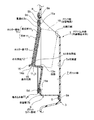
図1は、本発明に係る第1の実施の形態を採用した自動車用内装部品であるドアトリムの斜視図、図2は図1の円内を拡大して描画した斜視図、図3は図1の円内を描画した分解斜視図、図4は図1におけるホルダー部材の分解斜視図、図5は比較的小径の収納物品であるドリンク缶を収容した状態の図2のA−A断面図、図6は同じく比較的大径の収納物品であるドリンク缶を収容した状態の図2のA−A断面図である。
【0038】
図1乃至図6によれば、ドアトリム本体1は、アッパートリム2とロアトリム3との上下二分割体から構成され、外観上のアクセント効果を付与するために、アッパートリム2は例えば樹脂芯材の表面に表皮材を貼着してなる貼り合せ成形体から構成すると共に、ロアトリム3は例えばPP樹脂等の合成樹脂の射出成形体から構成されている。
【0039】
ロアトリム3には、アームレスト部4が膨出形成されると共にスピーカグリル5が装着されている他に、略中央下部に開口部6を有するポケット部7を有して構成している。
【0040】
ポケット部7は、ロアトリム3の裏面側に複数個の取付けボス8を形成し、取付けボス8にポケットカバー部材9の取付け孔9aを嵌合し、取付け孔9aより突出した取付けボス部8の先端を熱加締めすることにより、ポケットカバー部材9をロアトリム3の裏面側に装着してポケット状の収納部を形成して構成している。
【0041】
ポケットカバー部材9には、その略中央部に位置するように、ロアトリム3の裏面側に凸状となった凹陥部9bを形成し、凹陥部9bには略長円形の貫通孔9cが形成されている。
【0042】
凹陥部9bには、複数個の取付けボス9dが立設されており、取付けボス11dに収納物品例えばドリンク缶10、10aを把持するホルダー部13を有するホルダー部材11の取付け孔11aを嵌合して、取付け孔11aから突出した取付けボス9dの先端部を熱加締めすることにより、ホルダー部材11は、ポケットカバー部材9の裏面側に装着されている。
【0043】
ホルダー部材11は、合成樹脂等の硬質材料により形成した芯材111と芯材111のポケット部7の前面壁7a側を被覆する表皮材112とで構成している。
【0044】
表皮材112は、その外周端部に弾性変形可能な断面略コ字状に折曲形成された巻き込み部112aを有している。
【0045】
巻き込み部112aは、芯材111の外周端末部を弾性的に巻き込むことによって、表皮材112を芯材111に装着している。
【0046】
この時、芯材111側の孔111aと表皮材112側の孔112bとが一致して、取付けボス11bが挿通する貫通孔11cを構成している。
【0047】
表皮材112の上段部から下端やや中央側における裏面側には、複数の小片突起12が形成されて、貫通孔11cからポケット部7の背面壁7bに表出するホルダー部13を形成している。
【0048】
すなわち、小片突起12は、芯材111に対向するように突出形成されていて、ホルダー部13をポケット部7の内部側からドリンク缶10,10aにより弾性変形させることにより、芯材111に圧接して弾性的に変形させ倒すことによって、ポケット部7の前面壁7aとの間の間隙巾寸法を拡大可能に構成している。
【0049】
この結果、ホルダー部13は、収容物品であるドリンク缶10,10aの胴部を弾性的に受け入れるように構成されていることになる。
【0050】
更に、ホルダー部13の下端部には、ポケット部7内側において凹状となる段部13aが形成され、ドリンク缶10、10aがホルダー部13およびポケット部7の前面壁7aの間に挟合された時に、ドリンク缶10,10aの下端部を段部13aが支持するように構成している。
【0051】
芯材111側には、段部13aの裏面側が勘合する段状部111bが形成されている。
【0052】
段部13aと略同等の高さ位置における表皮材112の裏面側に、小片突起12より背高の係合突起14を形成し、係合突起14を芯材111に形成した係合孔部15に挿入係合することによって、芯材111に対する表皮材112の位置決めを行うと共に、係合突起14に設けた引っ掛け孔14aを、芯材111の裏面側に突設した引っ掛け片16に引っ掛けることにより、係合突起14が係合孔部15から抜け出さないように構成した。
【0053】
この結果、芯材111の外端部に表皮材112側の巻き込み部112aを巻き込む場合、芯材111に対して表皮材112は位置決めされていることになり、孔111aと孔112bとを簡単に一致させることができる。
【0054】
そして、図5に示すように、ポケット部7内に比較的小径のドリンク缶10,10aを収容する場合には、小片突起12を芯材111によって少し倒れさせることによって、ホルダー部13を芯材111側に弾性変形させ、ドリンク缶10の下端部(底部)を段部13aに支持させるようになっている。
【0055】
又、図6に示すように、ポケット部7内に比較的大径のドリンク缶10aを収容する場合には、小片突起12を芯材111に圧接させて大きく倒れさせることによって、ホルダー部13を芯材111側に大きく弾性変形させ、ドリンク缶10の下端部(底部)を段部13aに支持させるようになっている。
【0056】
上記のように構成する本発明に係る第1の実施の形態によれば、ホルダー部材11のホルダー部13により、大径のドリンク缶10aがポケット部7に収容された際に、ホルダー部13がドリンク缶10aホルダーホルダー部13と開口部6における前面壁7a側との間に挟着保持できることになり、収容物品の大きさに関わらず柔軟性あるポケット部構造であるといえる。
【0057】
又、ホルダー部材11は、合成樹脂等の硬質材料により形成した芯材111と芯材111を被覆する表皮材112とで構成することによって、ポケット部7の内部にホルダー部13を貫通孔9cを通して表出していても、見栄えを低下させることがない。
【0058】
又、表皮材112の外周端部に弾性変形可能な断面略コ字状の巻き込み部112aを形成し、巻き込み部112aを芯材111の外周端末部に弾性的に巻き込むことによって、表皮材112を芯材111に装着したことにより、芯材111への表皮材112の装着は、従来のようなスタッカー止めや接着剤を用いなくても、簡単に可能となる。
【0059】
又、表皮材112の裏面側に複数の小片突起12を芯材111に対して対向するように突出形成して、小片突起12を芯材111に圧接させて弾性的に変形させ倒すことによって、ポケット部7の前面壁7aとホルダー部13の間の間隙巾寸法を拡大可能に構成したことから、大径のドリンク缶10a等の収容物品も簡単に収容可能となり、しかも、収容物品を柔らかくしかも堅固に把持することができる。
【0060】
又、ホルダー部材11におけるホルダー部13をポケット部7の背面壁7bに凹設することによって、ホルダー部13の下端側に段部13aを設けて、段部13aによりホルダー部13およびポケット部7の前面壁7aに挟合されたドリンク缶10,10aの下端部を支持するように構成したことから、ホルダー部13により把持されたドリンク缶10,10aを段部13aにより支持することにより、更に、ドリンク缶10,10aの収納を安定的に行うことができる。
【0061】
又、表皮材112の裏面側に、小片突起12より背高の係合突起14を形成し、係合突起14を芯材111に形成した係合孔部15に挿入係合することによって、芯材111に対する表皮材112の位置決めを行うように構成したことから、係合突起14を係合孔部15に挿入係合することによって、芯材111に対し表皮材112を簡単に位置決めでき、表皮材112の芯材111への装着を簡単正確にすることができる。
【0062】
図7は本発明に係る第2の実施の形態を示している。
【0063】
図7によれば、上記第1実施の形態における表皮材112の巻き込み部112aを廃止して、表皮材112の外周端部を、ホルダー部材11のポケット部7への装着によって、ポケット部7と芯材111との間で挟着し、表皮材112を芯材111に装着したもので、その他の構成は第1の実施の形態と同一構成となっている。
【0064】
第2の実施の形態によれば、芯材111への表皮材112の装着が、従来のようなスタッカー止めや接着剤を用いなくても、簡単に可能となり、しかも、上記第1の実施の形態のような巻き込み部112aの芯材111への巻き込み作業を廃止して、装着工数を軽減している。
【0065】
なお、上記2つの実施の形態においては、ホルダー部材11をポケット部7の背面壁7b側に設けたが、これに限定されるものでなく、前面壁7a側に設ける構成でもよい。この場合、ホルダー部材11が、ロアトリム3の表面側に表出することになるが、ロアトリム3の表面側に凹部を設け、この凹部にホルダー部材11を埋設すると共に、ロアトリム3の表皮で被覆すれば、美観上或いは安全上等の問題はない。
【0066】
又、上記実施の形態では、自動車用内装部品として、ドアトリムを例にして説明したが、これに限定されるものでなく、例えば、ラゲージサイドトリムやリヤサイドトリム等の内装部品にも適用できる。
【0067】
【発明の効果】
以上説明したように、本発明は、ホルダー部材のホルダー部により、大径のドリンク缶等の収容物品がポケット部に収容された際に、ホルダー部が収容物品の形状に合わせて弾性変形し、当該収容物品を弾性的に受け入れて、ホルダー部とポケット部の前面壁との間に挟着保持できることになり、収容物品の大きさに対して柔軟性のあるポケット部構造であるといえる。
【図面の簡単な説明】
【図1】本発明に係る第1の実施の形態を採用した自動車用内装部品であるドアトリムの斜視図である。
【図2】図1の円内を拡大して描画した斜視図である。
【図3】図1の円内を描画した分解斜視図である。
【図4】図1におけるホルダー部材の分解斜視図である。
【図5】比較的小径の収納物品であるドリンク缶を収容した状態の図2のA−A断面図である。
【図6】同じく比較的大径の収納物品であるドリンク缶を収容した状態の図2のA−A断面図である。
【図7】本発明に係る第2の実施の形態を採用した自動車用内装部品であるドアトリムの要部を描画した断面図である。
【図8】従来における自動車用内装部品であるドアトリムの斜視図である。
【図9】図8におけるポケット部付近を拡大して描画した斜視図である。
【符号の説明】
1 ドアトリム本体(内装部品本体)
6 開口部
7 ポケット部
7a 前面壁
7b 背面壁
9 ポケットカバー部材
9c 貫通孔
10,10a ドリンク缶(収容物品)
11 ホルダー部材
111 芯材
112 表皮材
112a 巻き込み部
12 小片突起
13 ホルダー部
13a 段部
14 係合突起
15 係合孔部[0001]
BACKGROUND OF THE INVENTION
The present invention relates to a pocket device provided in an automobile interior part, for example, a door trim, and more particularly, to a pocket device for an automobile interior part having a pocket portion that can stably accommodate an accommodated article such as a drink can.
[0002]
[Prior art]
As a conventional pocket device for this type of automobile interior part, for example, the one shown in FIGS. 8 and 9 is known (see Patent Document 1).
[0003]
[Patent Document 1]
JP 2000-142201 A (paragraphs 0012 to 0023 and FIGS. 1 and 2 etc.)
[0004]
According to FIGS. 8 and 9, the door trim body a is composed of an upper and lower divided body of an upper trim b and a lower trim c, and a pocket portion e having an opening d in the upper portion is provided on the lower trim c side. .
[0005]
The front end side of the pocket part e bulges out to the vehicle compartment side to form a holder part f.
[0006]
The holder part f is configured to have a holder opening g that communicates with the opening part d and has a depth dimension set larger than that of the opening part d.
[0007]
And the plate-shaped guide rib h is integrally formed in the inner wall surface of the holder part f.
[0008]
The guide rib h is set obliquely downward with respect to the insertion direction of the drink can i.
[0009]
As a result, when the occupant accommodates the drink can i in the holder part f, as shown in FIG. 9, even if the drink can i is inserted roughly from the holder opening g, the bottom of the drink can i becomes the guide rib h. At the end, the bottom of the drink can i slides down on the surface of the guide rib 32, and the drink can i can be accommodated in the holder part f.
[0010]
[Problems to be solved by the invention]
However, since the guide rib h has a plate-like rib shape, it has a fixed shape, and the gap width dimension with the rear wall j of the pocket portion e is fixed.
[0011]
For this reason, even if an attempt is made to accommodate an accommodated article such as a drink can i having a diameter larger than the gap width dimension, it is blocked by the guide rib h and cannot be accommodated in the holder portion f.
[0012]
In view of this point, the present invention has an object to provide a pocket device provided in an automotive interior part capable of forming a flexible pocket portion that can easily accommodate a stored article such as a large drink can. Yes.
[0013]
[Means for Solving the Problems]
In order to achieve the above object, a pocket device provided in an automobile interior part according to the present invention comprises a front wall and a back wall by attaching a pocket cover member to a pocket installation site of an interior part body such as a door trim. forming a pocket having, before forming the wall and one in the through hole of the rear wall, of the holder member for gripping the accommodating articles from the back side of one of the front wall and back wall of the pocket portion in the through hole the holder portion in a state of being exposed into the pocket portion, and installing the holder member in one of the front wall and back wall of the pocket portion, and a holder portion of the holder member, to accept accommodating articles elastically elastically deformable configured Subeku, the holder member is constituted by a skin material which covers the formed core material and core material of a hard material such as a synthetic resin, and, Hol The front part of the pocket part is formed by projecting a plurality of small piece projections on the back side of the skin material so as to face the core material, and pressing the small piece projections against the core material to deform elastically The gap width between the other side of the wall and the back wall is configured to be enlarged so that the stored article can be sandwiched and held between the front wall and the back wall of the holder part and the pocket part. It is characterized by comprising.
[0014]
According to the present invention, when a stored article such as a large-sized drink can is accommodated in the pocket portion due to elastic deformation of the holder portion, the holder portion is elastically deformed according to the shape of the accommodated article, It can be elastically received and can be sandwiched and held between the holder portion and the front wall of the pocket portion, and it can be said that the pocket portion structure is flexible with respect to the size of the accommodated article.
[0015]
In addition, the holder member in the pocket device provided in the automobile interior part according to the present invention is constituted by a core material formed of a hard material such as a synthetic resin and a skin material covering the core material, so that the interior of the pocket portion Even if it is exposed through the through hole, the appearance does not deteriorate.
[0021]
Further , according to the present invention, since the small protrusion is elastically deformed and falls down, the size of the gap between the holder part and the other side of the front wall and the back wall of the pocket part can be enlarged. An accommodation article such as a can can be easily accommodated, and the accommodation article can be gripped softly and firmly.
[0036]
DETAILED DESCRIPTION OF THE INVENTION
Hereinafter, a first embodiment of the present invention will be described with reference to FIGS.
[0037]
FIG. 1 is a perspective view of a door trim that is an interior part for an automobile adopting the first embodiment according to the present invention, FIG. 2 is an enlarged perspective view of a circle in FIG. 1, and FIG. FIG. 4 is an exploded perspective view of the holder member in FIG. 1, FIG. 5 is a cross-sectional view taken along the line AA of FIG. 6 is a cross-sectional view taken along the line AA of FIG. 2 in a state where a drink can which is a storage article having a relatively large diameter is accommodated.
[0038]
According to FIGS. 1 to 6, the door trim main body 1 is composed of an upper and lower divided body of an upper trim 2 and a
[0039]
The
[0040]
The
[0041]
The
[0042]
A plurality of mounting
[0043]
Holder
[0044]
The
[0045]
The winding
[0046]
At this time, the hole 11 2 b of the core 11 1 side of the
[0047]
On the back side of the lower end slightly center side from the upper portion of the
[0048]
That is, the
[0049]
As a result, the
[0050]
Furthermore, a
[0051]
On the side of the
[0052]
On the back side of the
[0053]
As a result, when involving
[0054]
As shown in FIG. 5, when the
[0055]
Further, as shown in FIG. 6, when a relatively large-sized drink can 10a is accommodated in the
[0056]
According to the first embodiment of the present invention configured as described above, when the large-sized drink can 10a is accommodated in the
[0057]
Further, the
[0058]
Moreover, the elasticity of the deformable substantially U-shaped
[0059]
Further, a plurality of
[0060]
Further, the
[0061]
Further, by forming an
[0062]
FIG. 7 shows a second embodiment according to the present invention.
[0063]
According to FIG. 7, the winding
[0064]
According to the second embodiment, it is possible to easily attach the
[0065]
In the above-described two embodiments, the
[0066]
In the above embodiment, the door trim has been described as an example of the automobile interior part. However, the present invention is not limited to this, and can be applied to interior parts such as a luggage side trim and a rear side trim.
[0067]
【The invention's effect】
As described above, according to the present invention, the holder portion of the holder member is elastically deformed according to the shape of the accommodated article when the accommodated article such as a large-diameter drink can is accommodated in the pocket portion, The accommodated article can be elastically received and held between the holder part and the front wall of the pocket part, and it can be said that the pocket part structure is flexible with respect to the size of the accommodated article.
[Brief description of the drawings]
FIG. 1 is a perspective view of a door trim that is an interior part for an automobile that employs a first embodiment of the present invention.
FIG. 2 is an enlarged perspective view of the circle in FIG.
3 is an exploded perspective view depicting the inside of a circle in FIG. 1. FIG.
4 is an exploded perspective view of the holder member in FIG. 1. FIG.
5 is a cross-sectional view taken along the line AA of FIG. 2 in a state where a drink can which is a relatively small-diameter storage article is stored.
6 is a cross-sectional view taken along the line AA of FIG. 2 in a state where a drink can which is a storage article having a relatively large diameter is accommodated.
FIG. 7 is a cross-sectional view depicting a main part of a door trim which is an automotive interior part employing a second embodiment according to the present invention.
FIG. 8 is a perspective view of a door trim which is a conventional interior part for an automobile.
9 is an enlarged perspective view of the vicinity of a pocket portion in FIG.
[Explanation of symbols]
1 Door trim body (interior part body)
6
DESCRIPTION OF
Claims (1)
Priority Applications (1)
| Application Number | Priority Date | Filing Date | Title |
|---|---|---|---|
| JP2003112822A JP4247381B2 (en) | 2003-04-17 | 2003-04-17 | Pocket device for interior parts for automobiles |
Applications Claiming Priority (1)
| Application Number | Priority Date | Filing Date | Title |
|---|---|---|---|
| JP2003112822A JP4247381B2 (en) | 2003-04-17 | 2003-04-17 | Pocket device for interior parts for automobiles |
Publications (3)
| Publication Number | Publication Date |
|---|---|
| JP2004314826A JP2004314826A (en) | 2004-11-11 |
| JP2004314826A5 JP2004314826A5 (en) | 2006-05-25 |
| JP4247381B2 true JP4247381B2 (en) | 2009-04-02 |
Family
ID=33472928
Family Applications (1)
| Application Number | Title | Priority Date | Filing Date |
|---|---|---|---|
| JP2003112822A Expired - Fee Related JP4247381B2 (en) | 2003-04-17 | 2003-04-17 | Pocket device for interior parts for automobiles |
Country Status (1)
| Country | Link |
|---|---|
| JP (1) | JP4247381B2 (en) |
Families Citing this family (3)
| Publication number | Priority date | Publication date | Assignee | Title |
|---|---|---|---|---|
| US7594686B2 (en) * | 2007-08-21 | 2009-09-29 | Toyota Motor Engineering & Manufacturing North America, Inc. | Automotive door trim map pocket umbrella holder |
| JP5929593B2 (en) * | 2012-07-30 | 2016-06-08 | マツダ株式会社 | Automotive door trim structure |
| JP5767200B2 (en) * | 2012-11-27 | 2015-08-19 | 豊田鉄工株式会社 | Overlapped composite parts |
-
2003
- 2003-04-17 JP JP2003112822A patent/JP4247381B2/en not_active Expired - Fee Related
Also Published As
| Publication number | Publication date |
|---|---|
| JP2004314826A (en) | 2004-11-11 |
Similar Documents
| Publication | Publication Date | Title |
|---|---|---|
| US9783133B2 (en) | Magnet fastener with resilient support including at least one projection | |
| US20050236859A1 (en) | Mounting structure for console | |
| EP1449992A2 (en) | Method of releasably securing a trunklid latch release and assembly therefor | |
| JP2002220020A5 (en) | ||
| JP4247381B2 (en) | Pocket device for interior parts for automobiles | |
| JP2009029328A (en) | Trim clip suitable for trim for curtain side air bag | |
| JP5552464B2 (en) | Assembly structure for vehicle interior materials | |
| JP4530359B2 (en) | Pocket structure in interior lining | |
| JP2602378Y2 (en) | Clip mounting seat for body interior parts | |
| JP3775631B2 (en) | Tonneau cover mounting structure | |
| JP2001315561A (en) | Installing structure of housing type assist grip | |
| JP2003165333A (en) | Sun visor for vehicles | |
| JP4192056B2 (en) | Headrest storage structure | |
| JP3942067B2 (en) | Automotive door lining | |
| JP3804749B2 (en) | Automotive door trim device | |
| JP2606669Y2 (en) | Clip mounting seat for body interior parts | |
| JP2003205739A (en) | Sun visor for vehicles | |
| US7338103B2 (en) | Collapsible cover for vehicle interior | |
| JP4372516B2 (en) | Vehicle sun visor | |
| JPH11291826A (en) | Fitting structure for article holder to front pillar | |
| JP6721497B2 (en) | Door frame garnish | |
| JP2000062539A (en) | Upside down structure for synthetic resin parts | |
| JP2002046471A (en) | Corner piece mounting structure of automobile door | |
| JP2004114786A (en) | Pocket structure provided in car interior trim part | |
| JP2022100795A (en) | Vehicular sun visor with ticket holder |
Legal Events
| Date | Code | Title | Description |
|---|---|---|---|
| A521 | Written amendment |
Free format text: JAPANESE INTERMEDIATE CODE: A523 Effective date: 20060404 |
|
| A621 | Written request for application examination |
Free format text: JAPANESE INTERMEDIATE CODE: A621 Effective date: 20060404 |
|
| A977 | Report on retrieval |
Free format text: JAPANESE INTERMEDIATE CODE: A971007 Effective date: 20080612 |
|
| A131 | Notification of reasons for refusal |
Free format text: JAPANESE INTERMEDIATE CODE: A131 Effective date: 20080617 |
|
| A521 | Written amendment |
Free format text: JAPANESE INTERMEDIATE CODE: A523 Effective date: 20080808 |
|
| TRDD | Decision of grant or rejection written | ||
| A01 | Written decision to grant a patent or to grant a registration (utility model) |
Free format text: JAPANESE INTERMEDIATE CODE: A01 Effective date: 20081119 |
|
| A01 | Written decision to grant a patent or to grant a registration (utility model) |
Free format text: JAPANESE INTERMEDIATE CODE: A01 |
|
| A61 | First payment of annual fees (during grant procedure) |
Free format text: JAPANESE INTERMEDIATE CODE: A61 Effective date: 20081218 |
|
| FPAY | Renewal fee payment (event date is renewal date of database) |
Free format text: PAYMENT UNTIL: 20120123 Year of fee payment: 3 |
|
| R150 | Certificate of patent or registration of utility model |
Free format text: JAPANESE INTERMEDIATE CODE: R150 |
|
| LAPS | Cancellation because of no payment of annual fees |