JP4245286B2 - Catadioptric optical system and exposure apparatus provided with the optical system - Google Patents
Catadioptric optical system and exposure apparatus provided with the optical system Download PDFInfo
- Publication number
- JP4245286B2 JP4245286B2 JP2001309516A JP2001309516A JP4245286B2 JP 4245286 B2 JP4245286 B2 JP 4245286B2 JP 2001309516 A JP2001309516 A JP 2001309516A JP 2001309516 A JP2001309516 A JP 2001309516A JP 4245286 B2 JP4245286 B2 JP 4245286B2
- Authority
- JP
- Japan
- Prior art keywords
- optical system
- reflecting mirror
- reticle
- lens
- catadioptric
- Prior art date
- Legal status (The legal status is an assumption and is not a legal conclusion. Google has not performed a legal analysis and makes no representation as to the accuracy of the status listed.)
- Expired - Fee Related
Links
Images


Classifications
-
- G—PHYSICS
- G02—OPTICS
- G02B—OPTICAL ELEMENTS, SYSTEMS OR APPARATUS
- G02B17/00—Systems with reflecting surfaces, with or without refracting elements
- G02B17/08—Catadioptric systems
- G02B17/0892—Catadioptric systems specially adapted for the UV
-
- H10P76/00—
-
- G—PHYSICS
- G02—OPTICS
- G02B—OPTICAL ELEMENTS, SYSTEMS OR APPARATUS
- G02B17/00—Systems with reflecting surfaces, with or without refracting elements
- G02B17/08—Catadioptric systems
- G02B17/0836—Catadioptric systems using more than three curved mirrors
- G02B17/0844—Catadioptric systems using more than three curved mirrors off-axis or unobscured systems in which all of the mirrors share a common axis of rotational symmetry
-
- G—PHYSICS
- G03—PHOTOGRAPHY; CINEMATOGRAPHY; ANALOGOUS TECHNIQUES USING WAVES OTHER THAN OPTICAL WAVES; ELECTROGRAPHY; HOLOGRAPHY
- G03F—PHOTOMECHANICAL PRODUCTION OF TEXTURED OR PATTERNED SURFACES, e.g. FOR PRINTING, FOR PROCESSING OF SEMICONDUCTOR DEVICES; MATERIALS THEREFOR; ORIGINALS THEREFOR; APPARATUS SPECIALLY ADAPTED THEREFOR
- G03F7/00—Photomechanical, e.g. photolithographic, production of textured or patterned surfaces, e.g. printing surfaces; Materials therefor, e.g. comprising photoresists; Apparatus specially adapted therefor
- G03F7/70—Microphotolithographic exposure; Apparatus therefor
- G03F7/70216—Mask projection systems
- G03F7/70225—Optical aspects of catadioptric systems, i.e. comprising reflective and refractive elements
-
- G—PHYSICS
- G03—PHOTOGRAPHY; CINEMATOGRAPHY; ANALOGOUS TECHNIQUES USING WAVES OTHER THAN OPTICAL WAVES; ELECTROGRAPHY; HOLOGRAPHY
- G03F—PHOTOMECHANICAL PRODUCTION OF TEXTURED OR PATTERNED SURFACES, e.g. FOR PRINTING, FOR PROCESSING OF SEMICONDUCTOR DEVICES; MATERIALS THEREFOR; ORIGINALS THEREFOR; APPARATUS SPECIALLY ADAPTED THEREFOR
- G03F7/00—Photomechanical, e.g. photolithographic, production of textured or patterned surfaces, e.g. printing surfaces; Materials therefor, e.g. comprising photoresists; Apparatus specially adapted therefor
- G03F7/70—Microphotolithographic exposure; Apparatus therefor
- G03F7/70216—Mask projection systems
- G03F7/70275—Multiple projection paths, e.g. array of projection systems, microlens projection systems or tandem projection systems
Landscapes
- Physics & Mathematics (AREA)
- General Physics & Mathematics (AREA)
- Optics & Photonics (AREA)
- Lenses (AREA)
- Exposure And Positioning Against Photoresist Photosensitive Materials (AREA)
- Exposure Of Semiconductors, Excluding Electron Or Ion Beam Exposure (AREA)
Description
【0001】
【発明の属する技術分野】
本発明は反射屈折光学系および該光学系を備えた露光装置に関し、特に半導体素子などをフォトリソグラフィ工程で製造する際に使用される露光装置に最適な高解像の反射屈折型の投影光学系に関する。
【0002】
【従来の技術】
近年、半導体素子の製造や半導体チップ実装基板の製造では、微細化がますます進んでおり、パターンを焼き付ける露光装置ではより解像力の高い投影光学系が要求されてきている。この高解像の要求を満足するには、露光光を短波長化し、且つNA(投影光学系の開口数)を大きくしなければならない。しかしながら、露光光の波長が短くなると、光の吸収のため実用に耐える光学ガラスの種類が限られてくる。たとえば、波長が180nm以下になると、実用上使える硝材は蛍石だけとなる。
【0003】
この場合、屈折光学部材(レンズ、平行平面板など)だけで投影光学系を構成すると、形成された屈折型の投影光学系では色収差の補正が全く不可能となる。換言すると、要求される解像力を有する投影光学系を屈折光学部材だけで構成することは非常に難しいものとなる。これに対して、反射光学部材すなわち反射鏡のみで投影光学系を構成することも試みられている。
【0004】
しかしながら、この場合、形成される反射型の投影光学系は大型化し、且つ反射面の非球面化が必要となる。なお、反射面を高精度に非球面化することは、製作の面で極めて困難である。そこで、短波長光の使用に耐える光学ガラスからなる屈折光学部材と反射鏡とを組み合わせた、いわゆる反射屈折型の縮小光学系が種々提案されている。
【0005】
【発明が解決しようとする課題】
その中で、凹面反射鏡を1枚だけ用いて中間像を1回だけ形成するタイプの反射屈折光学系が知られている。このタイプの反射屈折光学系では、凹面反射鏡を含む往復兼用光学系部分が負レンズだけを含み、正のパワーを有する屈折光学部材を含んでいない。その結果、光束が広がった状態で凹面反射鏡に入射するため、凹面反射鏡の径が大きくなりがちであった。
【0006】
特に、凹面反射鏡を含む往復兼用光学系部分が完全対称型の構成を有する場合、この往復兼用光学系部分での収差の発生を極力抑えて後続の屈折光学系部分の収差補正負担を軽くしている。しかしながら、対称型の往復兼用光学系を採用しているため、第1面付近でのワーキングディスタンスを十分に確保しにくく、また光路分岐のためにハーフプリズムを使用しなければならなかった。
【0007】
また、中間像の形成位置よりも後方に配置される2次結像光学系に凹面反射鏡を使用する場合、光学系の必要な明るさを確保するためには、光束が広がった状態で凹面反射鏡に入射することになる。その結果、凹面反射鏡の径が大きくなりがちであり、その小型化が困難であった。
【0008】
一方、複数枚の反射鏡を用いて中間像を1回だけ形成するタイプの反射屈折光学系も知られている。このタイプの反射屈折光学系では、屈折光学系部分のレンズ枚数を削減できる可能性がある。しかしながら、このタイプの反射屈折光学系では、以下の不都合があった。
【0009】
上述のような構成の往復兼用光学系部分を縮小側である第2面側に配置するタイプの反射屈折光学系では、縮小倍率の関係から、反射鏡で反射された後の第2面(ウェハ面)までの距離を十分に長く確保することができない。このため、この光路中にあまり多くの枚数のレンズを挿入することができず、得られる光学系の明るさが限られた値にならざるを得なかった。また、高い開口数を有する光学系をたとえ実現することができたとしても、限られた長さの光路中に多くの屈折光学部材が配置されるため、第2面であるウェハ面と最も第2面側のレンズ面との距離、いわゆるワーキングディスタンスWDを十分に長く確保することができなかった。
【0010】
従来の反射屈折光学系においては、光路を折り曲げる必要があり、必然的に複数の光軸(光学系を構成する屈折曲面または反射曲面の曲率中心を連ねる直線のことをいう)を有することになる。その結果、光学系を形成するために複数の鏡筒を要し、光軸相互の調整作業が非常に困難になり、高精度の光学系を実現することができなかった。なお、中央に開口部(光透過部)を有する一対の反射鏡を用いることにより、すべての光学部材を単一の直線状光軸に沿って配置したタイプの反射屈折光学系も可能である。しかしながら、このタイプの反射屈折光学系では、反射鏡で反射されることなく光軸に沿って進行する不要光を遮るために、中心光束の遮蔽すなわち中心遮蔽が必要になる。その結果、中心遮蔽に起因して特定の周波数のパターンでコントラストの低下が起こるという不都合があった。
【0011】
また、従来の反射屈折光学系では、有効な視野絞りおよび開口絞りを設置すべき位置を確保することができなかった。さらに、上述したように、従来の反射屈折光学系では、ワーキングディスタンスを十分に長く確保することができなかった。また、上述したように、従来の反射屈折光学系では、凹面反射鏡が大型化し易く、光学系の小型化を図ることができなかった。
【0012】
さらに、EP1069448A1に開示された反射屈折光学系では、第2面側(ウェハ側)のワーキングディスタンスが確保され、単一光軸に沿って構成されているという利点があるが、第1面側(マスク側)のワーキングディスタンス(第1面であるマスク面と最も第1面側のレンズ面との距離)を十分に長く確保することができないという不都合があった。また、WO01/51979A2に開示された反射屈折光学系では、反射鏡の径が大きくなり過ぎるため、十分に大きな開口数を達成することができないという不都合があった。同様に、特開2001−228401号公報に開示された反射屈折光学系においても、反射鏡の径が大きくなり過ぎるため、十分に大きな開口数を達成することができないという不都合があった。
【0013】
本発明は、前述の課題に鑑みてなされたものであり、調整が容易で高精度に光学系を製造することができ、高解像を達成することのできる反射屈折光学系を提供することを目的とする。
【0018】
さらに、本発明の反射屈折光学系を投影光学系として使用し、0.1μm以下の高解像で良好な投影露光を行うことのできる露光装置を提供することを目的とする。
【0019】
また、本発明の露光装置を用いて、たとえば0.1μm以下の高解像で良好な投影露光を行うことにより、高精度なマイクロデバイスを製造することのできるマイクロデバイス製造方法を提供することを目的とする。
【0020】
【課題を解決するための手段】
前記課題を解決するために、本発明の第1発明では、少なくとも2つの反射鏡を有し、第1面からの光に基づいて前記第1面の第1中間像を形成するための第1結像光学系と、
少なくとも2つの反射鏡を有し、前記第1結像光学系を介した光に基づいて前記第1面の第2中間像を形成するための第2結像光学系と、
前記第2結像光学系を介した光に基づいて前記第1面の最終像を第2面上に形成するための屈折型の第3結像光学系とを備え、
前記第1結像光学系、前記第2結像光学系および前記第3結像光学系を構成するすべての光学部材が単一の直線状光軸に沿って配置されていることを特徴とする反射屈折光学系を提供する。
【0021】
第1発明の好ましい態様によれば、前記第1結像光学系と前記第2結像光学系との間の光路中にはフィールドレンズが配置されている。また、前記第1結像光学系は、前記2つの反射鏡と、少なくとも1つのレンズ成分とを有することが好ましい。さらに、前記第1結像光学系と前記フィールドレンズとの合成光学系は、第1面側および第2面側にテレセントリックな光学系を構成していることが好ましい。
【0022】
また、第1発明の好ましい態様によれば、前記第1結像光学系は、前記2つの反射鏡の間の光路中に配置された少なくとも1つの負レンズ成分を有する。また、前記第2結像光学系は、前記2つの反射鏡の間の光路中に配置された少なくとも1つの負レンズ成分を有することが好ましい。
【0023】
本発明の第2発明では、第1面と第2面との間の光路中に前記第1面の中間像を2回形成し、前記第1面の第3回目の中間像を最終像として前記第2面上に形成する反射屈折光学系であって、すべての光学部材が単一の直線状光軸に沿って配置されていることを特徴とする反射屈折光学系を提供する。この場合、前記中間像は、前記光軸から離れた位置に形成されることが好ましい。
【0024】
本発明の第3発明では、単一の直線状光軸に沿って配置された複数の反射鏡を有する反射屈折光学系であって、第1面上において前記光軸から離れた矩形状の領域の像を第2面上に形成することを特徴とする反射屈折光学系を提供する。この場合、前記反射屈折光学系は、該反射屈折光学系で形成される像領域を規定する視野絞りと、該反射屈折光学系の開口数を規定する開口絞りとを備えていることが好ましい。
【0025】
本発明の第4発明では、少なくとも第1反射鏡と第2反射鏡とを有し、第1面からの光に基づいて前記第1面の第1中間像を形成するための第1結像光学系と、
少なくとも第3反射鏡と第4反射鏡とを有し、前記第1結像光学系を介した光に基づいて前記第1面の第2中間像を形成するための第2結像光学系と、
前記第2結像光学系を介した光に基づいて前記第1面の最終像を第2面上に形成するための屈折型の第3結像光学系とを備え、
前記第1結像光学系、前記第2結像光学系および前記第3結像光学系を構成するすべての光学部材が単一の直線状光軸に沿って配置され、
前記第1反射鏡、前記第2反射鏡、前記第3反射鏡および前記第4反射鏡のうちの2つの反射鏡の反射面側の直前に少なくとも1つの負レンズがそれぞれ配置されていることを特徴とする反射屈折光学系を提供する。
【0026】
第4発明の好ましい態様によれば、前記2つの反射鏡の反射面側の直前に少なくとも1つの負レンズがそれぞれ配置されていることにより倍率の色収差の補正が行われ、倍率色収差係数LATは、|LAT|<5×10⁻⁶の条件を満足する。また、前記2つの反射鏡の反射面側の直前に少なくとも1つの負レンズがそれぞれ配置されていることにより軸上の色収差の補正が行われ、軸上色収差係数AXは、|AX|<2×10⁻⁴の条件を満足することが好ましい。
【0027】
本発明の第4発明では、前記第1面に設定されたマスクを照明するための照明系と、前記マスクに形成されたパターンの像を前記第2面に設定された感光性基板上に形成するための第1発明〜第3発明の反射屈折光学系とを備えていることを特徴とする露光装置を提供する。この場合、前記反射屈折光学系に対して前記マスクおよび前記感光性基板を相対移動させて、前記マスクパターンを前記感光性基板上に走査露光することが好ましい。
【0028】
本発明の第5発明では、第4発明の露光装置により前記マスクのパターンを前記感光性基板上に露光する露光工程と、前記露光工程により露光された前記感光性基板を現像する現像工程とを含むことを特徴とするマイクロデバイスの製造方法を提供する。
【0029】
【発明の実施の形態】
図1は、本発明の反射屈折光学系の基本的な構成を説明するための図である。なお、図1では、本発明の反射屈折光学系が走査露光型の露光装置の投影光学系に適用されている。図1に示すように、本発明の反射屈折光学系は、第1面に配置された投影原版としてのレチクルRのパターンの第1中間像を形成するための第1結像光学系G1を備えている。なお、第1結像光学系G1は、少なくとも2つの反射鏡、すなわち第1反射鏡および第2反射鏡を有する。
【0030】
第1結像光学系G1を介した光は、少なくとも2つの反射鏡、すなわち第3反射鏡および第4反射鏡を有する第2結像光学系G2を介して、レチクルRのパターンの第2中間像を形成する。第2結像光学系G2を介した光は、反射鏡を含むことなく屈折光学部材を有する屈折型の第3結像光学系G3を介して、レチクルRのパターンの最終像を第2面に配置された感光性基板としてのウェハW上に形成する。第1結像光学系G1、第2結像光学系G2および第3結像光学系G3を構成するすべての光学部材が、単一の直線状光軸AXに沿って配置されている。
【0031】
さらに具体的な態様によれば、第1結像光学系G1と第2結像光学系G2との間の光路中に、フィールドレンズFLが配置されている。ここで、フィールドレンズFLは、第1中間像の形成に関して積極的に寄与することなく、第1結像光学系G1と第2結像光学系G2とを整合接続する機能を有する。また、第1結像光学系G1は、2つの反射鏡に加えて、少なくとも1つのレンズ成分を有する。こうして、第1結像光学系G1とフィールドレンズFLとの合成光学系は、レチクル側(第1面側)およびウェハ側(第2面側)にテレセントリックな光学系を構成する。なお、第2結像光学系G2と第3結像光学系G3との間の光路中にも、必要に応じて、フィールドレンズが配置される。
【0032】
また、具体的な態様によれば、第1結像光学系G1および第2結像光学系G2のうち少なくとも一方の光学系では、2つの反射鏡の間の光路中に、少なくとも1つの負レンズ成分(L13、L21)が配置されていることが好ましい。この構成により、屈折光学部材(レンズ成分)を単一種の光学材料で形成しても、色収差の良好な補正が可能となる。
【0033】
また、反射屈折光学系で形成される像領域を規定する視野絞りFSを、第1結像光学系G1と第2結像光学系G2との間のフィールドレンズFLの近傍、または第2結像光学系G2と第3結像光学系G3との間のフィールドレンズの近傍に配置することができる。この場合、照明光学系に視野絞りを設けなくてもよい構成とすることができる。さらに、第3結像光学系G3の光路中に、開口絞りASを配置することができる。
【0034】
以上のように、本発明の反射屈折光学系では、複数の光軸を有する従来の反射屈折光学系とは異なり、すべての光学部材が単一の光軸AXに沿って配置されている。したがって、光学系を形成するために複数の鏡筒を要することなく、光軸相互の調整作業も不要となり、単一光軸AXに沿った各光学部材の傾きや位置ずれなどを光学的に検知し易くなるので、高精度の光学系を製造することができる。また、この構成により、単一光軸AXを重力方向(鉛直方向)に一致させると、重力によるレンズのたわみが回転対称になるように設定することが可能になり、光学調整により結像性能の劣化を小さく抑えることが可能となる。
【0035】
特に、露光装置の投影光学系に適用された場合、単一光軸AXに沿って直立姿勢で使用することにより、レチクルRおよびウェハWを重力方向に直交する面(すなわち水平面)に沿って互いに平行に配置するとともに、投影光学系を構成するすべてのレンズを重力方向の単一光軸AXに沿って水平に配置することができる。その結果、レチクルR、ウェハW、および投影光学系を構成するすべてのレンズが水平に保持され、自重による非対称な変形を受けることなく、光学調整や機械設計や高解像度の確保などにおいて非常に有利である。
【0036】
また、本発明では、第3結像光学系G3の屈折光学系部分が正の屈折力(パワー)を有するために正になりがちなペッツバール和を、第1結像光学系G1および第2結像光学系G2における凹面反射鏡部分の負のペッツバール和により相殺し、全体のペッツバール和を完全に0に抑えることができる。
【0037】
なお、反射鏡を含むすべての光学部材を単一の光軸に沿って配置する構成では、反射鏡に対してどのように光路を設定するかが、大きな問題となる。1つの解決策として、前述したように、反射鏡の中央に開口部(光透過部)を形成し、その中央開口部を介して光路を設定する技術が考えられる。しかしながら、この従来技術では、必然的に入射瞳部分において中心遮蔽を形成せざるを得ず、この中心遮蔽に起因して光学結像性能の低下を招くことになる。
【0038】
これに対し、本発明では、第1結像光学系G1において、レチクルパターンからの光束が第1反射鏡の外側を廻り込んで第2反射鏡に入射する。そして、第2反射鏡で反射された光束は、第1反射鏡で反射された後、第2反射鏡の外側を廻り込んで第1中間像を形成する。さらに、第2結像光学系G2において、第1中間像からの光束は、第3反射鏡の外側を廻り込んで第4反射鏡に入射する。そして、第4反射鏡で反射された光束は、第3反射鏡で反射された後、第4反射鏡の外側を廻り込んで第2中間像を形成する。本発明では、第1結像光学系G1と第2結像光学系G2とが、第1中間像の形成位置に関してほぼ対称に構成されている。その結果、レチクル側のワーキングディスタンス(最もレチクル側の光学面とレチクルとの間の光軸に沿った距離)を大きく確保することができる。つまり、第2結像光学系G2を介して形成される第2中間像の位置を第3反射鏡から遠ざけるように設定することにより、レチクル側のワーキングディスタンスを大きく確保することができる。シャップマンの色消しの原理「An achromat of the Schupmann (Refer R. Kingstake, “Lens Design Fundamentals”, Academic Press, 1978, Page 89)」によれば、負レンズからの共役像(レチクルR、中間像)までの距離差(図1では、レチクルRから第2反射鏡までの距離をcとし、第2反射鏡から第1反射鏡までの距離をbとし、第1反射鏡から中間像までの距離をaとすると、a+b−c)が大きいと、色補正が困難である。本発明では、第1結像光学系G1と第2結像光学系G2とが第1中間像の形成位置に関してほぼ対称に構成されているため、第1結像光学系G1の負レンズからの共役像までの距離差(a+b−c)を第2結像光学系G2で相殺(キャンセル)することができ、色収差補正の観点においても有利である。
【0039】
以上のような構成を採ることにより、入射瞳での中心遮蔽を回避することができ、ひいては中心遮蔽に起因する光学結像特性の低下を回避することができる。なお、反射屈折光学系全体の結像倍率を適宜選択することにより、各反射鏡の外側を廻り込む光路の設定が容易になる。その結果、図1に示すように、レチクルフィールドにおいて光軸AXから偏心した比較的大きな矩形状の照明領域IRに形成されたレチクルパターンの最終像を、ウェハフィールドにおいて光軸AXから偏心した比較的大きな矩形状の実効露光領域ER上に形成することができる。これに対応して、レチクルパターンの第1中間像および第2中間像は、光軸AXから離れた位置に形成されることになる。
【0040】
このように、本発明の反射屈折光学系を投影光学系として搭載した露光装置では、レチクルRおよびウェハWを所定の方向(スキャン方向)に沿って移動させながら、矩形状の照明領域IRおよび実効露光領域ERに基づく走査露光を行うことができる。これに対し、すべての光学部材が単一光軸に沿って配置された反射屈折光学系を投影光学系として搭載した従来の露光装置では、比較的大きな矩形状の照明領域および実効露光領域を確保することができず、細長い円弧状の照明領域および実効露光領域に基づく走査露光を行っていた。
【0041】
この場合、従来の露光装置では、実効露光領域の形状が細長い円弧状であるため、走査露光に際して実効露光領域が投影光学系の焦点深度内に常に納まるようにウェハステージの傾きを調整することが困難であった。また、従来の露光装置では、実効露光領域の形状が細長い円弧状であるため、スキャン方向に沿ったレチクルRおよびウェハWの所要移動量、すなわちスキャン幅が大きくなってしまう。本発明では、実効露光領域の形状が比較的大きい矩形状であるため、走査露光に際して実効露光領域が投影光学系の焦点深度内に常に納まるようにウェハステージの傾きを調整することが容易であり、スキャン幅も小さくなる。
【0042】
【実施例】
以下、本発明の実施例を、添付図面に基づいて説明する。
図2は、本発明の各実施例にかかる反射屈折光学系を投影光学系として備えた露光装置の全体構成を概略的に示す図である。なお、図2において、投影光学系PLを構成する反射屈折光学系の基準光軸AXに平行にZ軸を、光軸AXに垂直な面内において図2の紙面に平行にY軸を、紙面に垂直にX軸を設定している。
【0043】
図示の露光装置は、紫外領域の照明光を供給するための光源100として、F2レーザー光源(発振中心波長157.6nm)を備えている。光源100から射出された光は、照明光学系ILを介して、所定のパターンが形成されたレチクル(マスク)Rを均一に照明する。なお、光源100と照明光学系ILとの間の光路はケーシング(不図示)で密封されており、光源100から照明光学系IL中の最もレチクル側の光学部材までの空間は、露光光の吸収率が低い気体であるヘリウムガスや窒素などの不活性ガスで置換されているか、あるいはほぼ真空状態に保持されている。
【0044】
レチクルRは、レチクルホルダRHを介して、レチクルステージRS上においてXY平面に平行に保持されている。レチクルRには転写すべきパターンが形成されており、パターン領域全体のうちX方向に沿って長辺を有し且つY方向に沿って短辺を有する矩形状のパターン領域が照明される。レチクルステージRSは、図示を省略した駆動系の作用により、レチクル面(すなわちXY平面)に沿って二次元的に移動可能であり、その位置座標はレチクル移動鏡RMを用いた干渉計RIFによって計測され且つ位置制御されるように構成されている。
【0045】
レチクルRに形成されたパターンからの光は、反射屈折型の投影光学系PLを介して、感光性基板であるウェハW上にレチクルパターン像を形成する。ウェハWは、ウェハテーブル(ウェハホルダ)WTを介して、ウェハステージWS上においてXY平面に平行に保持されている。そして、レチクルR上での矩形状の照明領域に光学的に対応するように、ウェハW上ではX方向に沿って長辺を有し且つY方向に沿って短辺を有する矩形状の露光領域にパターン像が形成される。ウェハステージWSは、図示を省略した駆動系の作用によりウェハ面(すなわちXY平面)に沿って二次元的に移動可能であり、その位置座標はウェハ移動鏡WMを用いた干渉計WIFによって計測され且つ位置制御されるように構成されている。
【0046】
図3は、ウェハ上に形成される矩形状の露光領域(すなわち実効露光領域)と基準光軸との位置関係を示す図である。図3に示すように、各実施例(ただし第6実施例を除く)では、基準光軸AXを中心とした半径A(最大像高に対応)を有する円形状の領域(イメージサークル)IF内において、基準光軸AXから−Y方向に偏心した位置に所望の大きさを有する矩形状の実効露光領域ERが設定されている。ここで、実効露光領域ERのX方向の長さはLXであり、そのY方向の長さはLYである。
【0047】
したがって、図1に示すように、レチクルR上では、基準光軸AXから+Y方向に偏心した位置に実効露光領域ERに対応した大きさおよび形状を有する矩形状の照明領域IRが形成されていることになる。すなわち、基準光軸AXを中心とした半径B(最大物体高に対応)を有する円形状の領域内において、基準光軸AXから+Y方向に偏心した位置に所望の大きさを有する矩形状の照明領域IRが設定されている。
【0048】
また、図示の露光装置では、投影光学系PLを構成する光学部材のうち最もレチクル側に配置された光学部材(各実施例ではレンズL11)と最もウェハ側に配置された光学部材(第1および第2実施例ではレンズL38,第3実施例ではレンズL312,第4実施例ではレンズL39,第5、第6および第9実施例ではレンズL315,第7および第8実施例ではレンズL317)との間で投影光学系PLの内部が気密状態を保つように構成され、投影光学系PLの内部の気体はヘリウムガスや窒素などの不活性ガスで置換されているか、あるいはほぼ真空状態に保持されている。
【0049】
さらに、照明光学系ILと投影光学系PLとの間の狭い光路には、レチクルRおよびレチクルステージRSなどが配置されているが、レチクルRおよびレチクルステージRSなどを密封包囲するケーシング(不図示)の内部に窒素やヘリウムガスなどの不活性ガスが充填されているか、あるいはほぼ真空状態に保持されている。
【0050】
また、投影光学系PLとウェハWとの間の狭い光路には、ウェハWおよびウェハステージWSなどが配置されているが、ウェハWおよびウェハステージWSなどを密封包囲するケーシング(不図示)の内部に窒素やヘリウムガスなどの不活性ガスが充填されているか、あるいはほぼ真空状態に保持されている。このように、光源100からウェハWまでの光路の全体に亘って、露光光がほとんど吸収されることのない雰囲気が形成されている。
【0051】
上述したように、投影光学系PLによって規定されるレチクルR上の照明領域およびウェハW上の露光領域(すなわち実効露光領域ER)は、Y方向に沿って短辺を有する矩形状である。したがって、駆動系および干渉計(RIF、WIF)などを用いてレチクルRおよびウェハWの位置制御を行いながら、矩形状の露光領域および照明領域の短辺方向すなわちY方向に沿ってレチクルステージRSとウェハステージWSとを、ひいてはレチクルRとウェハWとを反対の方向へ(すなわち反対の向きへ)同期的に移動(走査)させることにより、ウェハW上には露光領域の長辺に等しい幅を有し且つウェハWの走査量(移動量)に応じた長さを有する領域に対してレチクルパターンが走査露光される。
【0052】
各実施例において、本発明の反射屈折光学系からなる投影光学系PLは、第1面に配置されたレチクルRのパターンの第1中間像を形成するための反射屈折型の第1結像光学系G1と、第1結像光学系G1を介した光に基づいてレチクルRのパターンの第2中間像を形成するための反射屈折型の第2結像光学系G2と、第2結像光学系G2を介した光に基づいて第2面に配置されたウェハW上にレチクルパターンの最終像(レチクルパターンの縮小像)を形成するための屈折型の第3結像光学系G3とを備えている。
【0053】
なお、各実施例において、第1結像光学系G1、第2結像光学系G2および第3結像光学系G3を構成するすべての光学部材が単一の直線状光軸AXに沿って配置されている。また、第1結像光学系G1と第2結像光学系G2との間の光路中には、第1フィールドレンズが配置されている。さらに、第2結像光学系G2と第3結像光学系G3との間の光路中には、第2フィールドレンズが配置されている。なお、基準光軸AXは、重力方向(すなわち鉛直方向)に沿って位置決めされている。その結果、レチクルRおよびウェハWは、重力方向と直交する面すなわち水平面に沿って互いに平行に配置されている。加えて、投影光学系PLを構成するすべての光学部材(レンズおよび反射鏡)も、基準光軸AX上において水平面に沿って配置されている。
【0054】
各実施例において、投影光学系PLを構成するすべての屈折光学部材(レンズ成分)には蛍石(CaF2結晶)を使用している。また、露光光であるF2 レーザー光の発振中心波長は157.6nmであり、157.6nm付近においてCaF2の屈折率は、+1pmの波長変化あたり−2×10⁻⁶の割合で変化し、−1pmの波長変化あたり+2×10⁻⁶の割合で変化する。換言すると、157.6nm付近において、CaF2の屈折率の分散(dn/dλ)は、2×10-6/pmである。
【0055】
したがって、各実施例において、中心波長157.6nmに対するCaF2の屈折率は1.560000である。そして、第1実施例、第2実施例および第4実施例では、157.6nm+0.5pm=157.6005nmに対するCaF2の屈折率は1.559999であり、157.6nm−0.5pm=157.5995nmに対するCaF2の屈折率は1.560001である。また、第3実施例、第5実施例および第6実施例では、157.6nm+0.3pm=157.6003nmに対するCaF2の屈折率は1.5599994であり、157.6nm−0.3pm=157.5997nmに対するCaF2の屈折率は1.5600006である。さらに、第7実施例〜第9実施例では、157.6nm+0.4pm=157.6004nmに対するCaF2の屈折率は1.5599992であり、157.6nm−0.4pm=157.5996nmに対するCaF2の屈折率は1.5600008である。
【0056】
また、各実施例において、非球面は、光軸に垂直な方向の高さをyとし、非球面の頂点における接平面から高さyにおける非球面上の位置までの光軸に沿った距離(サグ量)をzとし、頂点曲率半径をrとし、円錐係数をκとし、n次の非球面係数をCn としたとき、以下の数式(a)で表される。
【0057】
【数1】
z=(y2/r)/〔1+{1−(1+κ)・y2/r2}1/2〕
+C4・y4+C6・y6+C8・y8+C10・y10 (a)
各実施例において、非球面形状に形成されたレンズ面には面番号の右側に*印を付している。
【0058】
〔第1実施例〕
図4は、第1実施例にかかる反射屈折光学系(投影光学系PL)のレンズ構成を示す図である。図4の反射屈折光学系において、第1結像光学系G1は、レチクル側から順に、ウェハ側に非球面状の凸面を向けた正メニスカスレンズL11と、ウェハ側に非球面状の凸面を向けた正メニスカスレンズL12と、ウェハ側に平面に近い凹面を向けた凹面反射鏡M11と、レチクル側に凹面を向けた負メニスカスレンズL13と、レチクル側に凹面を向けた凹面反射鏡M12とから構成されている。
【0059】
また、第2結像光学系G2は、レチクル側から順に、ウェハ側に凹面を向けた凹面反射鏡M21と、レチクル側に凸面を向けた負メニスカスレンズL21と、レチクル側に平面に近い凹面を向けた凹面反射鏡M22とから構成されている。
【0060】
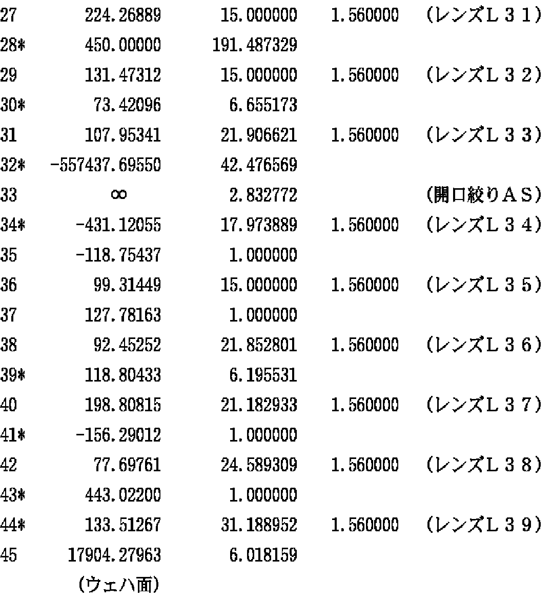
さらに、第3結像光学系G3は、レチクル側から順に、ウェハ側に非球面状の凸面を向けた負メニスカスレンズL31と、レチクル側に非球面状の凸面を向けた負メニスカスレンズL32と、ウェハ側に非球面状の凹面を向けた正メニスカスレンズL33と、開口絞りASと、レチクル側に非球面状の凹面を向けた正メニスカスレンズL34と、ウェハ側に非球面状の凹面を向けた正メニスカスレンズL35と、ウェハ側に非球面状の凹面を向けた正メニスカスレンズL36と、両凸レンズL37と、ウェハ側に非球面状の凸面を向けた両凸レンズL38とから構成されている。
【0061】
なお、第1結像光学系G1と第2結像光学系G2との間の光路中には、レチクル側から順に、レチクル側に非球面状の凹面を向けた正メニスカスレンズL41と、レチクル側に非球面状の凸面を向けた両凸レンズL42と、ウェハ側に非球面状の凹面を向けた正メニスカスレンズL43とから構成された第1フィールドレンズが配置されている。また、第2結像光学系G2と第3結像光学系G3との間の光路中には、レチクル側に非球面状の凸面を向けた両凸レンズL51から構成された第2フィールドレンズが配置されている。
【0062】
したがって、第1実施例では、レチクルRからの光が、正メニスカスレンズL11、正メニスカスレンズL12および負メニスカスレンズL13を介して、凹面反射鏡M12に入射する。凹面反射鏡M12で反射された光は、負メニスカスレンズL13を介して凹面反射鏡M11で反射された後、第1フィールドレンズ(L41〜L43)中にレチクルパターンの第1中間像を形成する。
【0063】
第1フィールドレンズ(L41〜L43)中に形成された第1中間像からの光は、凹面反射鏡M22で反射され、負メニスカスレンズL21を介して凹面反射鏡M21で反射された後、負メニスカスレンズL21を介して第2フィールドレンズL51の近傍にレチクルパターンの第2中間像を形成する。第2フィールドレンズL51の近傍に形成された第2中間像からの光は、第3結像光学系G3を構成する各レンズL31〜L38を介して、ウェハW上にレチクルパターンの最終像を形成する。
【0064】
次の表(1)に、第1実施例の反射屈折光学系の諸元の値を掲げる。表(1)の主要諸元において、λは露光光の中心波長を、βは投影倍率(全系の結像倍率)を、NAは像側(ウェハ側)開口数を、AはウェハW上でのイメージサークルIFの半径すなわち最大像高を、Bは最大像高Aに対応する最大物体高を、LXは実効露光領域ERのX方向に沿った寸法(長辺の寸法)を、LYは実効露光領域ERのY方向に沿った寸法(短辺の寸法)をそれぞれ表している。
【0065】
また、表(1)の光学部材諸元において、第1カラムの面番号はレチクル側からの面の順序を、第2カラムのrは各面の曲率半径(非球面の場合には頂点曲率半径:mm)を、第3カラムのdは各面の軸上間隔すなわち面間隔(mm)を、第4カラムのnは中心波長に対する屈折率をそれぞれ示している。なお、面間隔dは、反射される度にその符号を変えるものとする。したがって、面間隔dの符号は、凹面反射鏡M12から凹面反射鏡M11への光路中および凹面反射鏡M22から凹面反射鏡M21への光路中では負とし、その他の光路中では正としている。また、光の入射方向に関わらず、レチクル側に向かって凸面の曲率半径を正とし、レチクル側に向かって凹面の曲率半径を負としている。
【0066】
【表1】
(主要諸元)
λ=157.6nm
β=1/4
NA=0.70
A=17mm
B=68mm
LX=22mm
LY=5mm
2面
κ=0.000000
C4=−0.291653×10⁻⁶ C6=0.688361×10⁻¹¹
C8=−0.173883×10⁻¹⁵ C10=0.114644×10⁻¹⁸
4面
κ=0.000000
C4=0.245562×10⁻⁶ C6=0.937520×10⁻¹¹
C8=−0.121380×10⁻¹⁴ C10=0.619768×10⁻¹⁹
11面
κ=0.000000
C4=−0.317890×10⁻⁷ C6=−0.350349×10⁻¹¹
C8=0.549441×10⁻¹⁵ C10=−0.185236×10⁻¹⁹
13面
κ=0.000000
C4=0.274807×10⁻⁷ C6=−0.280710×10⁻¹¹
C8=−0.990831×10⁻¹⁶ C10=−0.764627×10⁻²⁰
16面
κ=0.000000
C4=0.507380×10⁻⁷ C6=−0.797166×10⁻¹¹
C8=−0.693684×10⁻¹⁶ C10=0.761192×10⁻²⁰
23面
κ=0.000000
C4=−0.124616×10⁻⁶ C6=0.245376×10⁻¹⁰
C8=−0.436363×10⁻¹⁴ C10=0.165599×10⁻¹⁸
26面
κ=0.000000
C4=−0.652972×10⁻⁷ C6=0.117653×10⁻¹⁰
C8=−0.107028×10⁻¹⁴ C10=0.613946×10⁻¹⁹
27面
κ=0.000000
C4=−0.272313×10⁻⁷ C6=−0.517344×10⁻¹¹
C8=−0.904051×10⁻¹⁵ C10=−0.601541×10⁻¹⁹
30面
κ=0.000000
C4=0.303099×10⁻⁶ C6=0.157674×10⁻¹⁰
C8=0.136800×10⁻¹⁴ C10=0.231671×10⁻¹⁸
32面
κ=0.000000
C4=−0.161006×10⁻⁶ C6=0.118724×10⁻¹⁰
C8=0.790687×10⁻¹⁵ C10=0.271051×10⁻¹⁹
37面
κ=0.000000
C4=0.894445×10⁻⁷ C6=0.728182×10⁻¹⁰
C8=−0.886021×10⁻¹⁴ C10=0.108877×10⁻¹⁷
41面
κ=0.000000
C4=0.677633×10⁻⁶ C6=−0.377321×10⁻⁹
C8=0.103549×10⁻¹² C10=0.227795×10⁻¹⁶
【0067】
図5は、第1実施例にかかる反射屈折光学系の横収差を示す図である。収差図において、Yは像高(mm)を示している。収差図から明らかなように、第1実施例では、波長幅が157.6nm±0.5pmの露光光に対して色収差が良好に補正されていることがわかる。また、球面収差、コマ収差、非点収差、ディストーション(歪曲収差)がほぼ無収差に近い状態まで良好に補正され、優れた結像性能を有することを確認している。
【0068】
〔第2実施例〕
図6は、第2実施例にかかる反射屈折光学系(投影光学系PL)のレンズ構成を示す図である。図6の反射屈折光学系において、第1結像光学系G1は、レチクル側から順に、ウェハ側に非球面状の凸面を向けた正メニスカスレンズL11と、ウェハ側に非球面状の凸面を向けた正メニスカスレンズL12と、ウェハ側に平面に近い凹面を向けた凹面反射鏡M11と、レチクル側に凹面を向けた負メニスカスレンズL13と、レチクル側に凹面を向けた凹面反射鏡M12とから構成されている。
【0069】
また、第2結像光学系G2は、レチクル側から順に、ウェハ側に凹面を向けた凹面反射鏡M21と、レチクル側に凸面を向けた負メニスカスレンズL21と、レチクル側に平面に近い凹面を向けた凹面反射鏡M22とから構成されている。
【0070】
さらに、第3結像光学系G3は、レチクル側から順に、ウェハ側に非球面状の凸面を向けた負メニスカスレンズL31と、レチクル側に非球面状の凸面を向けた負メニスカスレンズL32と、ウェハ側に非球面状の凸面を向けた両凸レンズL33と、開口絞りASと、レチクル側に非球面状の凸面を向けた両凸レンズL34と、レチクル側に凸面を向けた正メニスカスレンズL35と、ウェハ側に非球面状の凹面を向けた正メニスカスレンズL36と、レチクル側に凸面を向けた正メニスカスレンズL37と、ウェハ側に非球面状の凸面を向けた両凸レンズL38とから構成されている。
【0071】
なお、第1結像光学系G1と第2結像光学系G2との間の光路中には、レチクル側から順に、レチクル側に非球面状の凹面を向けた正メニスカスレンズL41と、レチクル側に非球面状の凸面を向けた正メニスカスレンズL42と、ウェハ側に非球面状の凹面を向けた正メニスカスレンズL43とから構成された第1フィールドレンズが配置されている。また、第2結像光学系G2と第3結像光学系G3との間の光路中には、レチクル側に非球面状の凸面を向けた両凸レンズL51から構成された第2フィールドレンズが配置されている。
【0072】
したがって、第2実施例では、レチクルRからの光が、正メニスカスレンズL11、正メニスカスレンズL12および負メニスカスレンズL13を介して、凹面反射鏡M12に入射する。凹面反射鏡M12で反射された光は、負メニスカスレンズL13を介して凹面反射鏡M11で反射された後、第1フィールドレンズ(L41〜L43)中にレチクルパターンの第1中間像を形成する。
【0073】
第1フィールドレンズ(L41〜L43)中に形成された第1中間像からの光は、凹面反射鏡M22で反射され、負メニスカスレンズL21を介して凹面反射鏡M21で反射された後、負メニスカスレンズL21を介して第2フィールドレンズL51の近傍にレチクルパターンの第2中間像を形成する。第2フィールドレンズL51の近傍に形成された第2中間像からの光は、第3結像光学系G3を構成する各レンズL31〜L38を介して、ウェハW上にレチクルパターンの最終像を形成する。
【0074】
次の表(2)に、第2実施例の反射屈折光学系の諸元の値を掲げる。表(2)の主要諸元において、λは露光光の中心波長を、βは投影倍率(全系の結像倍率)を、NAは像側(ウェハ側)開口数を、AはウェハW上でのイメージサークルIFの半径すなわち最大像高を、Bは最大像高Aに対応する最大物体高を、LXは実効露光領域ERのX方向に沿った寸法(長辺の寸法)を、LYは実効露光領域ERのY方向に沿った寸法(短辺の寸法)をそれぞれ表している。
【0075】
また、表(2)の光学部材諸元において、第1カラムの面番号はレチクル側からの面の順序を、第2カラムのrは各面の曲率半径(非球面の場合には頂点曲率半径:mm)を、第3カラムのdは各面の軸上間隔すなわち面間隔(mm)を、第4カラムのnは中心波長に対する屈折率をそれぞれ示している。なお、面間隔dは、反射される度にその符号を変えるものとする。したがって、面間隔dの符号は、凹面反射鏡M12から凹面反射鏡M11への光路中および凹面反射鏡M22から凹面反射鏡M21への光路中では負とし、その他の光路中では正としている。また、光の入射方向に関わらず、レチクル側に向かって凸面の曲率半径を正とし、レチクル側に向かって凹面の曲率半径を負としている。
【0076】
【表2】
(主要諸元)
λ=157.6nm
β=1/5
NA=0.8
A=21mm
B=105mm
LX=22mm
LY=5mm
2面
κ=0.000000
C4=−0.264407×10⁻⁷ C6=−0.476678×10⁻¹²
C8=0.155729×10⁻¹⁵ C10=−0.517698×10⁻²⁰
4面
κ=0.000000
C4=0.280731×10⁻⁷ C6=0.571906×10⁻¹²
C8=0.469828×10⁻¹⁷ C10=0.988050×10⁻²¹
11面
κ=0.000000
C4=0.275486×10⁻⁷ C6=−0.579812×10⁻¹¹
C8=0.188014×10⁻¹⁵ C10=−0.327703×10⁻²⁰
13面
κ=0.000000
C4=−0.305645×10⁻⁷ C6=−0.100924×10⁻¹¹
C8=0.185962×10⁻¹⁶ C10=−0.380314×10⁻²⁰
16面
κ=0.000000
C4=0.476746×10⁻⁷ C6=−0.515517×10⁻¹¹
C8=−0.536543×10⁻¹⁶ C10=0.833063×10⁻²⁰
23面
κ=0.000000
C4=−0.916646×10⁻⁷ C6=0.125088×10⁻¹¹
C8=−0.367721×10⁻¹⁶ C10=−0.108975×10⁻²⁰
26面
κ=0.000000
C4=−0.696241×10⁻⁷ C6=0.269136×10⁻¹⁰
C8=−0.305398×10⁻¹⁴ C10=0.112606×10⁻¹⁸
27面
κ=0.000000
C4=0.216592×10⁻⁷ C6=0.590674×10⁻¹¹
C8=0.832609×10⁻¹⁶ C10=−0.333598×10⁻¹⁹
30面
κ=0.000000
C4=0.180772×10⁻⁶ C6=0.105754×10⁻¹⁰
C8=0.691500×10⁻¹⁵ C10=0.189377×10⁻¹⁹
32面
κ=0.000000
C4=−0.173909×10⁻⁷ C6=0.507430×10⁻¹¹
C8=−0.989619×10⁻¹⁶ C10=−0.182632×10⁻¹⁹
37面
κ=0.000000
C4=0.764004×10⁻⁷ C6=0.873773×10⁻¹¹
C8=−0.285150×10⁻¹⁵ C10=0.481104×10⁻¹⁹
41面
κ=0.000000
C4=0.145715×10⁻⁶ C6=−0.124981×10⁻⁹
C8=0.704755×10⁻¹³ C10=−0.114853×10⁻¹⁶
【0077】
図7は、第2実施例にかかる反射屈折光学系の横収差を示す図である。収差図において、Yは像高(mm)を示している。収差図から明らかなように、第2実施例においても第1実施例と同様に、波長幅が157.6nm±0.5pmの露光光に対して色収差が良好に補正されていることがわかる。また、球面収差、コマ収差、非点収差、ディストーション(歪曲収差)がほぼ無収差に近い状態まで良好に補正され、優れた結像性能を有することを確認している。
【0078】
〔第3実施例〕
図8は、第3実施例にかかる反射屈折光学系(投影光学系PL)のレンズ構成を示す図である。図8の反射屈折光学系において、第1結像光学系G1は、レチクル側から順に、両凸レンズL11と、ウェハ側に平面に近い凹面を向けた凹面反射鏡M11と、レチクル側に凹面を向けた凹面反射鏡M12とから構成されている。
【0079】
また、第2結像光学系G2は、レチクル側から順に、ウェハ側に凹面を向けた凹面反射鏡M21と、レチクル側に凸面を向けた負メニスカスレンズL21と、レチクル側に平面に近い凹面を向けた凹面反射鏡M22とから構成されている。
【0080】
さらに、第3結像光学系G3は、レチクル側から順に、レチクル側に非球面状の凹面を向けた正メニスカスレンズL31と、レチクル側に凸面を向けた負メニスカスレンズL32と、レチクル側に凸面を向けた正メニスカスレンズL33と、ウェハ側に非球面状の凹面を向けた正メニスカスレンズL34と、両凸レンズL35と、レチクル側に非球面状の凹面を向けた負メニスカスレンズL36と、開口絞りASと、レチクル側に非球面状の凹面を向けた負メニスカスレンズL37と、ウェハ側に非球面状の凸面を向けた両凸レンズL38と、ウェハ側に非球面状の凹面を向けた正メニスカスレンズL39と、レチクル側に凸面を向けた正メニスカスレンズL310と、両凹レンズL311と、レチクル側に凸面を向けた正メニスカスレンズL312とから構成されている。
【0081】
なお、第1結像光学系G1と第2結像光学系G2との間の光路中には、レチクル側から順に、両凸レンズL41と、ウェハ側に非球面状の凸面を向けた両凸レンズL42とから構成された第1フィールドレンズが配置されている。また、第2結像光学系G2と第3結像光学系G3との間の光路中には、レチクル側から順に、レチクル側に凹面を向けた正メニスカスレンズL51と、両凸レンズL52ととから構成された第2フィールドレンズが配置されている。
【0082】
したがって、第3実施例では、レチクルRからの光が、両凸レンズL11を介して、凹面反射鏡M12に入射する。凹面反射鏡M12で反射された光は、凹面反射鏡M11で反射された後、第1フィールドレンズ(L41およびL42)を介してレチクルパターンの第1中間像を形成する。
【0083】
第1フィールドレンズ(L41およびL42)を介して形成された第1中間像からの光は、凹面反射鏡M22で反射され、負メニスカスレンズL21を介して凹面反射鏡M21で反射された後、負メニスカスレンズL21を介して、第2フィールドレンズ(L51およびL52)の近傍にレチクルパターンの第2中間像を形成する。第2中間像からの光は、第2フィールドレンズ(L51およびL52)、および第3結像光学系G3を構成する各レンズL31〜L312を介して、ウェハW上にレチクルパターンの最終像を形成する。
【0084】
次の表(3)に、第3実施例の反射屈折光学系の諸元の値を掲げる。表(3)の主要諸元において、λは露光光の中心波長を、βは投影倍率(全系の結像倍率)を、NAは像側(ウェハ側)開口数を、AはウェハW上でのイメージサークルIFの半径すなわち最大像高を、Bは最大像高Aに対応する最大物体高を、LXは実効露光領域ERのX方向に沿った寸法(長辺の寸法)を、LYは実効露光領域ERのY方向に沿った寸法(短辺の寸法)をそれぞれ表している。
【0085】
また、表(3)の光学部材諸元において、第1カラムの面番号はレチクル側からの面の順序を、第2カラムのrは各面の曲率半径(非球面の場合には頂点曲率半径:mm)を、第3カラムのdは各面の軸上間隔すなわち面間隔(mm)を、第4カラムのnは中心波長に対する屈折率をそれぞれ示している。なお、面間隔dは、反射される度にその符号を変えるものとする。したがって、面間隔dの符号は、凹面反射鏡M12から凹面反射鏡M11への光路中および凹面反射鏡M22から凹面反射鏡M21への光路中では負とし、その他の光路中では正としている。また、光の入射方向に関わらず、レチクル側に向かって凸面の曲率半径を正とし、レチクル側に向かって凹面の曲率半径を負としている。
【0086】
【表3】
(主要諸元)
λ=157.6nm
β=1/5
NA=0.8
A=18mm
B=90mm
LX=20mm
LY=5mm
8面
κ=0.000000
C4=0.120134×10⁻⁷ C6=−0.141075×10⁻¹²
C8=0.191837×10⁻¹⁷ C10=−0.169436×10⁻²²
19面
κ=0.000000
C4=−0.153558×10⁻⁷ C6=−0.750057×10⁻¹³
C8=−0.110884×10⁻¹⁶ C10=0.325196×10⁻²²
26面
κ=0.000000
C4=0.494425×10⁻⁷ C6=0.707114×10⁻¹²
C8=0.176474×10⁻¹⁶ C10=0.615523×10⁻²¹
29面
κ=0.000000
C4=−0.755499×10⁻⁸ C6=0.321947×10⁻¹¹
C8=−0.596697×10⁻¹⁷ C10=0.457591×10⁻²⁰
32面
κ=0.000000
C4=−0.509707×10⁻⁷ C6=−0.426764×10⁻¹¹
C8=0.576131×10⁻¹⁷ C10=−0.691255×10⁻²⁰
35面
κ=0.000000
C4=0.283140×10⁻⁹ C6=0.915262×10⁻¹²
C8=0.266523×10⁻¹⁶ C10=0.112707×10⁻²¹
37面
κ=0.000000
C4=0.443648×10⁻⁷ C6=0.354423×10⁻¹¹
C8=0.351861×10⁻¹⁶ C10=−0.206407×10⁻¹⁹
【0087】
図9は、第3実施例にかかる反射屈折光学系の横収差を示す図である。収差図において、Yは像高(mm)を示している。収差図から明らかなように、第3実施例では、波長幅が157.6nm±0.3pmの露光光に対して色収差が良好に補正されていることがわかる。また、球面収差、コマ収差、非点収差、ディストーション(歪曲収差)がほぼ無収差に近い状態まで良好に補正され、優れた結像性能を有することを確認している。
【0088】
〔第4実施例〕
図10は、第4実施例にかかる反射屈折光学系(投影光学系PL)のレンズ構成を示す図である。図10の反射屈折光学系において、第1結像光学系G1は、レチクル側から順に、ウェハ側に非球面状の凸面を向けた両凸レンズL11と、ウェハ側に非球面状の凹面を向けた負メニスカスレンズL12と、ウェハ側に平面に近い凹面を向けた凹面反射鏡M11と、レチクル側に凹面を向けた負メニスカスレンズL13と、レチクル側に凹面を向けた凹面反射鏡M12とから構成されている。
【0089】
また、第2結像光学系G2は、レチクル側から順に、ウェハ側に凹面を向けた凹面反射鏡M21と、レチクル側に凸面を向けた負メニスカスレンズL21と、レチクル側に平面に近い凹面を向けた凹面反射鏡M22とから構成されている。
【0090】
さらに、第3結像光学系G3は、レチクル側から順に、ウェハ側に非球面状の凹面を向けた正メニスカスレンズL31と、ウェハ側に非球面状の凹面を向けた負メニスカスレンズL32と、ウェハ側に非球面状の凹面を向けた正メニスカスレンズL33と、開口絞りASと、レチクル側に非球面状の凹面を向けた正メニスカスレンズL34と、レチクル側に凸面を向けた正メニスカスレンズL35と、ウェハ側に非球面状の凹面を向けた正メニスカスレンズL36と、ウェハ側に非球面状の凸面を向けた両凸レンズL37と、ウェハ側に非球面状の凹面を向けた正メニスカスレンズL38と、レチクル側に非球面状の凸面を向けた正メニスカスレンズL39とから構成されている。
【0091】
なお、第1結像光学系G1と第2結像光学系G2との間の光路中には、レチクル側から順に、レチクル側に凸面を向けた正メニスカスレンズL41と、ウェハ側に非球面状の凹面を向けた正メニスカスレンズL42と、ウェハ側に非球面状の凹面を向けた正メニスカスレンズL43とから構成された第1フィールドレンズが配置されている。また、第2結像光学系G2と第3結像光学系G3との間の光路中には、レチクル側から順に、ウェハ側に非球面状の凹面を向けた正メニスカスレンズL51と、ウェハ側に非球面状の凸面を向けた両凸レンズL52とから構成された第2フィールドレンズが配置されている。
【0092】
したがって、第4実施例では、レチクルRからの光が、両凸レンズL11、負メニスカスレンズL12および負メニスカスレンズL13を介して、凹面反射鏡M12に入射する。凹面反射鏡M12で反射された光は、負メニスカスレンズL13を介して凹面反射鏡M11で反射された後、第1フィールドレンズ(L41〜L43)中にレチクルパターンの第1中間像を形成する。
【0093】
第1フィールドレンズ(L41〜L43)中に形成された第1中間像からの光は、凹面反射鏡M22で反射され、負メニスカスレンズL21を介して凹面反射鏡M21で反射された後、負メニスカスレンズL21を介して第2フィールドレンズ(L51およびL52)中にレチクルパターンの第2中間像を形成する。第2フィールドレンズ(L51およびL52)中に形成された第2中間像からの光は、第3結像光学系G3を構成する各レンズL31〜L39を介して、ウェハW上にレチクルパターンの最終像を形成する。
【0094】
次の表(4)に、第4実施例の反射屈折光学系の諸元の値を掲げる。表(4)の主要諸元において、λは露光光の中心波長を、βは投影倍率(全系の結像倍率)を、NAは像側(ウェハ側)開口数を、AはウェハW上でのイメージサークルIFの半径すなわち最大像高を、Bは最大像高Aに対応する最大物体高を、LXは実効露光領域ERのX方向に沿った寸法(長辺の寸法)を、LYは実効露光領域ERのY方向に沿った寸法(短辺の寸法)をそれぞれ表している。
【0095】
また、表(4)の光学部材諸元において、第1カラムの面番号はレチクル側からの面の順序を、第2カラムのrは各面の曲率半径(非球面の場合には頂点曲率半径:mm)を、第3カラムのdは各面の軸上間隔すなわち面間隔(mm)を、第4カラムのnは中心波長に対する屈折率をそれぞれ示している。なお、面間隔dは、反射される度にその符号を変えるものとする。したがって、面間隔dの符号は、凹面反射鏡M12から凹面反射鏡M11への光路中および凹面反射鏡M22から凹面反射鏡M21への光路中では負とし、その他の光路中では正としている。また、光の入射方向に関わらず、レチクル側に向かって凸面の曲率半径を正とし、レチクル側に向かって凹面の曲率半径を負としている。
【0096】
【表4】
(主要諸元)
λ=157.6nm
β=1/5
NA=0.6
A=21mm
B=105mm
LX=22mm
LY=6mm
2面
κ=0.000000
C4=−0.815643×10⁻⁷ C6=0.413258×10⁻¹¹
C8=−0.113569×10⁻¹⁵ C10=0.147898×10⁻²⁰
4面
κ=0.000000
C4=0.114732×10⁻⁶ C6=−0.219867×10⁻¹¹
C8=0.617602×10⁻¹⁶ C10=−0.322366×10⁻²¹
14面
κ=0.000000
C4=−0.117278×10⁻⁶ C6=0.199688×10⁻¹¹
C8=0.688425×10⁻¹⁶ C10=−0.127291×10⁻²⁰
16面
κ=0.000000
C4=0.191460×10⁻⁶ C6=0.172729×10⁻¹¹
C8=−0.417938×10⁻¹⁵ C10=0.122892×10⁻¹⁹
24面
κ=0.000000
C4=0.101006×10⁻⁶ C6=−0.601731×10⁻¹¹
C8=0.336098×10⁻¹⁵ C10=−0.113255×10⁻¹⁹
26面
κ=0.000000
C4=−0.259409×10⁻⁶ C6=0.200455×10⁻¹⁰
C8=−0.886510×10⁻¹⁵ C10=0.203312×10⁻¹⁹
28面
κ=0.000000
C4=0.254720×10⁻⁶ C6=−0.499612×10⁻¹¹
C8=−0.101235×10⁻¹⁵ C10=0.475827×10⁻¹⁹
30面
κ=0.000000
C4=−0.122986×10⁻⁶ C6=−0.297417×10⁻¹⁰
C8=−0.286999×10⁻¹⁴ C10=−0.314877×10⁻¹⁸
32面
κ=0.000000
C4=0.260763×10⁻⁶ C6=0.278223×10⁻¹⁰
C8=0.311168×10⁻¹⁴ C10=0.409140×10⁻¹⁸
34面
κ=0.000000
C4=−0.246966×10⁻⁷ C6=−0.328800×10⁻¹¹
C8=0.155119×10⁻¹⁴ C10=0.481917×10⁻¹⁹
39面
κ=0.000000
C4=0.363517×10⁻⁶ C6=0.688387×10⁻¹²
C8=0.263082×10⁻¹⁴ C10=0.401937×10⁻¹⁸
41面
κ=0.000000
C4=0.171166×10⁻⁶ C6=−0.110988×10⁻¹⁰
C8=0.989095×10⁻¹⁵ C10=0.238040×10⁻¹⁸
43面
κ=0.000000
C4=0.130469×10⁻⁶ C6=0.132452×10⁻⁹
C8=−0.246540×10⁻¹³ C10=0.404311×10⁻¹⁷
44面
κ=0.000000
C4=0.736368×10⁻⁶ C6=0.554124×10⁻¹⁰
C8=0.111988×10⁻¹³ C10=0.498595×10⁻¹⁷
【0097】
図11は、第4実施例にかかる反射屈折光学系の横収差を示す図である。収差図において、Yは像高(mm)を示している。収差図から明らかなように、第4実施例においても第1実施例および第2実施例と同様に、波長幅が157.6nm±0.5pmの露光光に対して色収差が良好に補正されていることがわかる。また、球面収差、コマ収差、非点収差、ディストーション(歪曲収差)がほぼ無収差に近い状態まで良好に補正され、優れた結像性能を有することを確認している。
【0098】
〔第5実施例〕
図12は、第5実施例にかかる反射屈折光学系(投影光学系PL)のレンズ構成を示す図である。図12の反射屈折光学系において、第1結像光学系G1は、レチクル側から順に、レチクル側に凸面を向けた正メニスカスレンズL11と、ウェハ側に平面に近い凹面を向けた凹面反射鏡M11と、レチクル側に凹面を向けた負メニスカスレンズL12と、レチクル側に凹面を向けた凹面反射鏡M12とから構成されている。
【0099】
また、第2結像光学系G2は、レチクル側から順に、ウェハ側に凹面を向けた凹面反射鏡M21と、レチクル側に平面に近い凹面を向けた凹面反射鏡M22とから構成されている。
【0100】
さらに、第3結像光学系G3は、レチクル側から順に、両凹レンズL31と、ウェハ側に非球面状の凹面を向けた正メニスカスレンズL32と、両凸レンズL33と、レチクル側に凸面を向けた負メニスカスレンズL34と、レチクル側に凸面を向けた正メニスカスレンズL35と、ウェハ側に非球面状の凹面を向けた正メニスカスレンズL36と、両凸レンズL37と、レチクル側に凹面を向けた負メニスカスレンズL38と、開口絞りASと、レチクル側に非球面状の凹面を向けた負メニスカスレンズL39と、ウェハ側に非球面状の凸面を向けた両凸レンズL310と、レチクル側に凹面を向けた負メニスカスレンズL311と、ウェハ側に非球面状の凹面を向けた正メニスカスレンズL312と、レチクル側に凸面を向けた正メニスカスレンズL313と、レチクル側に凸面を向けた正メニスカスレンズL314と、両凸レンズL315とから構成されている。
【0101】
なお、第1結像光学系G1と第2結像光学系G2との間の光路中には、レチクル側から順に、両凸レンズL41と、ウェハ側に非球面状の凹面を向けた正メニスカスレンズL42とから構成された第1フィールドレンズが配置されている。また、第2結像光学系G2と第3結像光学系G3との間の光路中には、レチクル側から順に、レチクル側に非球面状の凹面を向けた正メニスカスレンズL51と、両凸レンズL52とから構成された第2フィールドレンズが配置されている。
【0102】
したがって、第5実施例では、レチクルRからの光が、正メニスカスレンズL11および負メニスカスレンズL12を介して、凹面反射鏡M12に入射する。凹面反射鏡M12で反射された光は、負メニスカスレンズL12を介して凹面反射鏡M11で反射された後、第1フィールドレンズ(L41およびL42)の近傍にレチクルパターンの第1中間像を形成する。
【0103】
第1中間像からの光は、第1フィールドレンズ(L41およびL42)を介して、凹面反射鏡M22および凹面反射鏡M21で順次反射された後、第2フィールドレンズ(L51およびL52)の近傍にレチクルパターンの第2中間像を形成する。第2中間像からの光は、第2フィールドレンズ(L51およびL52)、および第3結像光学系G3を構成する各レンズL31〜L315を介して、ウェハW上にレチクルパターンの最終像を形成する。
【0104】
次の表(5)に、第5実施例の反射屈折光学系の諸元の値を掲げる。表(5)の主要諸元において、λは露光光の中心波長を、βは投影倍率(全系の結像倍率)を、NAは像側(ウェハ側)開口数を、AはウェハW上でのイメージサークルIFの半径すなわち最大像高を、Bは最大像高Aに対応する最大物体高を、LXは実効露光領域ERのX方向に沿った寸法(長辺の寸法)を、LYは実効露光領域ERのY方向に沿った寸法(短辺の寸法)をそれぞれ表している。
【0105】
また、表(5)の光学部材諸元において、第1カラムの面番号はレチクル側からの面の順序を、第2カラムのrは各面の曲率半径(非球面の場合には頂点曲率半径:mm)を、第3カラムのdは各面の軸上間隔すなわち面間隔(mm)を、第4カラムのnは中心波長に対する屈折率をそれぞれ示している。なお、面間隔dは、反射される度にその符号を変えるものとする。したがって、面間隔dの符号は、凹面反射鏡M12から凹面反射鏡M11への光路中および凹面反射鏡M22から凹面反射鏡M21への光路中では負とし、その他の光路中では正としている。また、光の入射方向に関わらず、レチクル側に向かって凸面の曲率半径を正とし、レチクル側に向かって凹面の曲率半径を負としている。
【0106】
【表5】
(主要諸元)
λ=157.6nm
β=1/5
NA=0.8
A=18mm
B=90mm
LX=20mm
LY=5mm
12面
κ=0.000000
C4=0.181313×10⁻⁷ C6=0.145718×10⁻¹²
C8=−0.178341×10⁻¹⁷ C10=0.265148×10⁻²¹
15面
κ=0.000000
C4=−0.588707×10⁻⁷ C6=−0.844226×10⁻¹²
C8=−0.743823×10⁻¹⁶ C10=−0.197114×10⁻²¹
22面
κ=0.000000
C4=−0.294829×10⁻⁷ C6=0.384432×10⁻¹¹
C8=−0.393756×10⁻¹⁶ C10=−0.345603×10⁻²¹
30面
κ=0.000000
C4=0.100809×10⁻⁶ C6=0.669526×10⁻¹²
C8=−0.609327×10⁻¹⁷ C10=0.830042×10⁻²¹
36面
κ=0.000000
C4=−0.137850×10⁻⁶ C6=−0.508803×10⁻¹¹
C8=−0.272924×10⁻¹⁵ C10=−0.202953×10⁻¹⁹
39面
κ=0.000000
C4=−0.111530×10⁻⁶ C6=0.650079×10⁻¹¹
C8=0.157560×10⁻¹⁵ C10=−0.172336×10⁻¹⁹
43面
κ=0.000000
C4=0.170111×10⁻⁶ C6=−0.258296×10⁻¹¹
C8=0.608232×10⁻¹⁵ C10=0.232160×10⁻¹⁹
【0107】
図13は、第5実施例にかかる反射屈折光学系の横収差を示す図である。収差図において、Yは像高(mm)を示している。収差図から明らかなように、第5実施例においても第3実施例と同様に、波長幅が157.6nm±0.3pmの露光光に対して色収差が良好に補正されていることがわかる。また、球面収差、コマ収差、非点収差、ディストーション(歪曲収差)がほぼ無収差に近い状態まで良好に補正され、優れた結像性能を有することを確認している。
【0108】
〔第6実施例〕
図14は、第6実施例にかかる反射屈折光学系(投影光学系PL)のレンズ構成を示す図である。図14の反射屈折光学系において、第1結像光学系G1は、レチクル側から順に、レチクル側に凸面を向けた正メニスカスレンズL11と、ウェハ側に平面に近い凹面を向けた凹面反射鏡M11と、レチクル側に凹面を向けた凹面反射鏡M12とから構成されている。
【0109】
また、第2結像光学系G2は、レチクル側から順に、ウェハ側に凹面を向けた凹面反射鏡M21と、レチクル側に凸面を向けた負メニスカスレンズL21と、レチクル側に平面に近い凹面を向けた凹面反射鏡M22とから構成されている。
【0110】
さらに、第3結像光学系G3は、レチクル側から順に、両凹レンズL31と、ウェハ側に非球面状の凹面を向けた負メニスカスレンズL32と、レチクル側に凸面を向けた正メニスカスレンズL33と、両凹レンズL34と、レチクル側に凹面を向けた負メニスカスレンズL35と、ウェハ側に非球面状の凹面を向けた正メニスカスレンズL36と、両凸レンズL37と、レチクル側に凹面を向けた負メニスカスレンズL38と、開口絞りASと、レチクル側に非球面状の凹面を向けた正メニスカスレンズL39と、ウェハ側に非球面状の凸面を向けた両凸レンズL310と、レチクル側に凹面を向けた負メニスカスレンズL311と、ウェハ側に非球面状の凹面を向けた正メニスカスレンズL312と、レチクル側に凸面を向けた正メニスカスレンズL313と、レチクル側に凸面を向けた負メニスカスレンズL314と、両凸レンズL315とから構成されている。
【0111】
なお、第1結像光学系G1と第2結像光学系G2との間の光路中には、レチクル側から順に、レチクル側に凹面を向けた正メニスカスレンズL41と、ウェハ側に非球面状の凸面を向けた両凸レンズL42とから構成された第1フィールドレンズが配置されている。また、第2結像光学系G2と第3結像光学系G3との間の光路中には、レチクル側から順に、レチクル側に非球面状の凸面を向けた両凸レンズL51と、両凸レンズL52とから構成された第2フィールドレンズが配置されている。
【0112】
したがって、第6実施例では、レチクルRからの光が、正メニスカスレンズL11を介して、凹面反射鏡M12に入射する。凹面反射鏡M12で反射された光は、凹面反射鏡M11で反射された後、第1フィールドレンズ(L41およびL42)中にレチクルパターンの第1中間像を形成する。
【0113】
第1フィールドレンズ(L41およびL42)中に形成された第1中間像からの光は、凹面反射鏡M22で反射され、負メニスカスレンズL21を介して凹面反射鏡M21で反射された後、負メニスカスレンズL21を介して、第2フィールドレンズ(L51およびL52)の近傍にレチクルパターンの第2中間像を形成する。第2中間像からの光は、第2フィールドレンズ(L51およびL52)、および第3結像光学系G3を構成する各レンズL31〜L315を介して、ウェハW上にレチクルパターンの最終像を形成する。
【0114】
なお、上述の第1実施例〜第5実施例ではウェハW上に矩形状の実効露光領域ERが形成されるが、第6実施例では円弧状の実効露光領域ERが形成される。図15は、第6実施例においてウェハ上に形成される円弧状の実効露光領域と基準光軸との位置関係を示す図である。図15に示すように、第6実施例では、基準光軸AXを中心とした半径A(最大像高に対応)を有する円形状の領域(イメージサークル)IF内において、基準光軸AXから+Y方向に偏心した位置に所望の大きさを有する円弧状の実効露光領域ERが設定されている。ここで、円弧状の実効露光領域ERのX方向の長さはLX’であり、そのY方向の長さはLY’である。したがって、レチクルR上では、基準光軸AXから−Y方向に偏心した位置に円弧状の実効露光領域ERに対応した大きさおよび形状を有する円弧状の照明領域IRが形成されていることになる。すなわち、基準光軸AXを中心とした半径B(最大物体高に対応)を有する円形状の領域内において、基準光軸AXから−Y方向に偏心した位置に所望の大きさを有する円弧状の照明領域IRが設定されている。
【0115】
次の表(6)に、第6実施例の反射屈折光学系の諸元の値を掲げる。表(6)の主要諸元において、λは露光光の中心波長を、βは投影倍率(全系の結像倍率)を、NAは像側(ウェハ側)開口数を、AはウェハW上でのイメージサークルIFの半径すなわち最大像高を、Bは最大像高Aに対応する最大物体高を、LX’は円弧状の実効露光領域ERのX方向に沿った寸法を、LY’は円弧状の実効露光領域ERのY方向に沿った寸法をそれぞれ表している。
【0116】
また、表(6)の光学部材諸元において、第1カラムの面番号はレチクル側からの面の順序を、第2カラムのrは各面の曲率半径(非球面の場合には頂点曲率半径:mm)を、第3カラムのdは各面の軸上間隔すなわち面間隔(mm)を、第4カラムのnは中心波長に対する屈折率をそれぞれ示している。なお、面間隔dは、反射される度にその符号を変えるものとする。したがって、面間隔dの符号は、凹面反射鏡M12から凹面反射鏡M11への光路中および凹面反射鏡M22から凹面反射鏡M21への光路中では負とし、その他の光路中では正としている。また、光の入射方向に関わらず、レチクル側に向かって凸面の曲率半径を正とし、レチクル側に向かって凹面の曲率半径を負としている。
【0117】
【表6】
(主要諸元)
λ=157.6nm
β=1/5
NA=0.8
A=18mm
B=90mm
LX’=20mm
LY’=3mm
8面
κ=0.000000
C4=0.554200×10⁻⁸ C6=−0.280967×10⁻¹³
C8=0.778972×10⁻¹⁸ C10=−0.177500×10⁻²²
15面
κ=0.000000
C4=−0.109228×10⁻⁷ C6=−0.364285×10⁻¹²
C8=0.142762×10⁻¹⁶ C10=−0.362739×10⁻²¹
22面
κ=0.000000
C4=0.225626×10⁻⁷ C6=−0.154524×10⁻¹²
C8=0.164766×10⁻¹⁶ C10=0.164885×10⁻²⁰
30面
κ=0.000000
C4=0.379428×10⁻⁷ C6=0.163017×10⁻¹¹
C8=0.684667×10⁻¹⁶ C10=−0.115849×10⁻²⁰
36面
κ=0.000000
C4=−0.146106×10⁻⁶ C6=−0.502919×10⁻¹¹
C8=−0.270461×10⁻¹⁵ C10=−0.186877×10⁻¹⁹
39面
κ=0.000000
C4=−0.159225×10⁻⁶ C6=0.844367×10⁻¹¹
C8=0.120649×10⁻¹⁵ C10=−0.173041×10⁻¹⁹
43面
κ=0.000000
C4=0.204302×10⁻⁶ C6=−0.422928×10⁻¹¹
C8=0.824463×10⁻¹⁵ C10=0.719034×10⁻²⁰
【0118】
図16は、第6実施例にかかる反射屈折光学系の横収差を示す図である。収差図において、Yは像高(mm)を示している。収差図から明らかなように、第6実施例においても第3実施例および第5実施例と同様に、波長幅が157.6nm±0.3pmの露光光に対して色収差が良好に補正されていることがわかる。また、球面収差、コマ収差、非点収差、ディストーション(歪曲収差)がほぼ無収差に近い状態まで良好に補正され、優れた結像性能を有することを確認している。
【0119】
〔第7実施例〕
図17は、第7実施例にかかる反射屈折光学系(投影光学系PL)のレンズ構成を示す図である。図17の反射屈折光学系において、第1結像光学系G1は、レチクル側から順に、両凸レンズL11と、ウェハ側に平面に近い凸面を向けた凸面反射鏡M11と、レチクル側に凹面を向けた凹面反射鏡M12とから構成されている。
【0120】
また、第2結像光学系G2は、レチクル側から順に、ウェハ側に凹面を向けた凹面反射鏡M21と、レチクル側に凸面を向けた負メニスカスレンズL21と、レチクル側に凹面を向けた負メニスカスレンズL22と、レチクル側に凹面を向けた凹面反射鏡M22とから構成されている。
【0121】
さらに、第3結像光学系G3は、レチクル側から順に、レチクル側に凸面を向けた正メニスカスレンズL31と、レチクル側に凸面を向けた負メニスカスレンズL32と、ウェハ側に非球面状の凹面を向けた正メニスカスレンズL33と、レチクル側に凸面を向けた正メニスカスレンズL34と、レチクル側に凸面を向けた負メニスカスレンズL35と、レチクル側に凹面を向けた負メニスカスレンズL36と、ウェハ側に非球面状の凹面を向けた正メニスカスレンズL37と、両凸レンズL38と、レチクル側に凹面を向けた正メニスカスレンズL39と、レチクル側に凹面を向けた負メニスカスレンズL310と、レチクル側に非球面状の凹面を向けた負メニスカスレンズL311と、レチクル側に凸面を向けた正メニスカスレンズL312と、ウェハ側の非球面状の凸面を向けた両凸レンズL313と、レチクル側に凹面を向けた負メニスカスレンズL314と、ウェハ側に非球面状の凹面を向けた正メニスカスレンズL315と、レチクル側に凸面を向けた正メニスカスレンズL316と、レチクル側に凸面を向けた正メニスカスレンズL317とから構成されている。
【0122】
なお、第1結像光学系G1と第2結像光学系G2との間の光路中には、レチクル側から順に、両凸レンズL41と、ウェハ側に非球面状の凸面を向けた両凸レンズL42とから構成された第1フィールドレンズが配置されている。また、第2結像光学系G2と第3結像光学系G3との間の光路中には、レチクル側に非球面状の凸面を向けた両凸レンズL51から構成された第2フィールドレンズが配置されている。
【0123】
したがって、第7実施例では、レチクルRからの光が、両凸レンズL11を介して、凹面反射鏡M12に入射する。凹面反射鏡M12で反射された光は、凸面反射鏡M11で反射された後、第1フィールドレンズ(L41およびL42)の近傍にレチクルパターンの第1中間像を形成する。
【0124】
第1中間像からの光は、負メニスカスレンズL22を介して凹面反射鏡M22で反射された後、負メニスカスレンズL22および負メニスカスレンズL21を介して凹面反射鏡M21に入射する。凹面反射鏡M21で反射された光は、負メニスカスレンズL21を介して、第2フィールドレンズ(L51)の近傍にレチクルパターンの第2中間像を形成する。第2中間像からの光は、第3結像光学系G3を構成する各レンズL31〜L317を介して、ウェハW上にレチクルパターンの最終像を形成する。
【0125】
次の表(7)に、第7実施例の反射屈折光学系の諸元の値を掲げる。表(7)の主要諸元において、λは露光光の中心波長を、βは投影倍率(全系の結像倍率)を、NAは像側(ウェハ側)開口数を、AはウェハW上でのイメージサークルIFの半径すなわち最大像高を、Bは最大像高Aに対応する最大物体高を、LXは実効露光領域ERのX方向に沿った寸法(長辺の寸法)を、LYは実効露光領域ERのY方向に沿った寸法(短辺の寸法)をそれぞれ表している。
【0126】
また、表(7)の光学部材諸元において、第1カラムの面番号はレチクル側からの面の順序を、第2カラムのrは各面の曲率半径(非球面の場合には頂点曲率半径:mm)を、第3カラムのdは各面の軸上間隔すなわち面間隔(mm)を、第4カラムのnは中心波長に対する屈折率をそれぞれ示している。なお、面間隔dは、反射される度にその符号を変えるものとする。したがって、面間隔dの符号は、凹面反射鏡M12から凹面反射鏡M11への光路中および凹面反射鏡M22から凹面反射鏡M21への光路中では負とし、その他の光路中では正としている。また、光の入射方向に関わらず、レチクル側に向かって凸面の曲率半径を正とし、レチクル側に向かって凹面の曲率半径を負としている。さらに、表(7)の条件式対応値において、LATは倍率色収差係数を、AXは軸上色収差係数をそれぞれ示している。
【0127】
【表7】
(主要諸元)
λ=157.6nm
β=1/4
NA=0.845
A=18mm
B=72mm
LX=22mm
LY=4mm
8面
κ=0.000000
C4=0.118332×10⁻⁷ C6=−0.901477×10⁻¹³
C8=0.456579×10⁻¹⁸ C10=0.500107×10⁻²³
19面
κ=0.000000
C4=0.362526×10⁻⁷ C6=−0.325425×10⁻¹²
C8=−0.715942×10⁻¹⁷ C10=0.938233×10⁻²²
26面
κ=0.000000
C4=0.784516×10⁻⁷ C6=0.132181×10⁻¹¹
C8=0.390546×10⁻¹⁶ C10=0.194862×10⁻²⁰
34面
κ=0.000000
C4=0.770740×10⁻⁷ C6=0.108454×10⁻¹¹
C8=−0.141384×10⁻¹⁶ C10=−0.154327×10⁻²⁰
41面
κ=0.000000
C4=−0.111168×10⁻⁶ C6=−0.459164×10⁻¹¹
C8=−0.179391×10⁻¹⁵ C10=−0.627753×10⁻²⁰
46面
κ=0.000000
C4=−0.806181×10⁻⁷ C6=0.979363×10⁻¹¹
C8=−0.432122×10⁻¹⁵ C10=0.353438×10⁻²⁰
50面
κ=0.000000
C4=0.171550×10⁻⁶ C6=−0.506941×10⁻¹¹
C8=0.172612×10⁻¹⁴ C10=−0.907247×10⁻¹⁹
(条件式対応値)
LAT=−3.9×10⁻⁷
AX=−5.2×10⁻⁵
【0128】
図18および図19は、第7実施例にかかる反射屈折光学系の横収差を示す図である。収差図において、Yは像高(mm)を示している。収差図から明らかなように、第7実施例では、波長幅が157.6nm±0.4pmの露光光に対して色収差が良好に補正されていることがわかる。また、球面収差、コマ収差、非点収差、ディストーション(歪曲収差)がほぼ無収差に近い状態まで良好に補正され、優れた結像性能を有することを確認している。
【0129】
〔第8実施例〕
図20は、第8実施例にかかる反射屈折光学系(投影光学系PL)のレンズ構成を示す図である。図20の反射屈折光学系において、第1結像光学系G1は、レチクル側から順に、両凸レンズL11と、ウェハ側に平面に近い凸面を向けた凸面反射鏡M11と、レチクル側に凹面を向けた凹面反射鏡M12とから構成されている。
【0130】
また、第2結像光学系G2は、レチクル側から順に、ウェハ側に凹面を向けた凹面反射鏡M21と、レチクル側に凸面を向けた負メニスカスレンズL21と、レチクル側に凹面を向けた負メニスカスレンズL22と、レチクル側に凹面を向けた凹面反射鏡M22とから構成されている。
【0131】
さらに、第3結像光学系G3は、レチクル側から順に、レチクル側に凹面を向けた負メニスカスレンズL31と、レチクル側に凸面を向けた負メニスカスレンズL32と、両凸レンズL33と、ウェハ側に非球面状の凹面を向けた負メニスカスレンズL34と、両凹レンズL35と、レチクル側に凹面を向けた負メニスカスレンズL36と、ウェハ側に非球面状の凹面を向けた正メニスカスレンズL37と、両凸レンズL38と、レチクル側に凹面を向けた正メニスカスレンズL39と、レチクル側に凹面を向けた負メニスカスレンズL310と、レチクル側に非球面状の凹面を向けた負メニスカスレンズL311と、レチクル側に凸面を向けた正メニスカスレンズL312と、ウェハ側の非球面状の凸面を向けた両凸レンズL313と、レチクル側に凹面を向けた負メニスカスレンズL314と、ウェハ側に非球面状の凹面を向けた正メニスカスレンズL315と、レチクル側に凸面を向けた正メニスカスレンズL316と、レチクル側に凸面を向けた正メニスカスレンズL317とから構成されている。
【0132】
なお、第1結像光学系G1と第2結像光学系G2との間の光路中には、レチクル側から順に、両凸レンズL41と、ウェハ側に非球面状の凸面を向けた両凸レンズL42とから構成された第1フィールドレンズが配置されている。また、第2結像光学系G2と第3結像光学系G3との間の光路中には、レチクル側に非球面状の凹面を向けた正メニスカスレンズL51から構成された第2フィールドレンズが配置されている。
【0133】
したがって、第8実施例では、レチクルRからの光が、両凸レンズL11を介して、凹面反射鏡M12に入射する。凹面反射鏡M12で反射された光は、凸面反射鏡M11で反射された後、第1フィールドレンズ(L41およびL42)の近傍にレチクルパターンの第1中間像を形成する。
【0134】
第1中間像からの光は、負メニスカスレンズL22を介して凹面反射鏡M22で反射された後、負メニスカスレンズL22および負メニスカスレンズL21を介して凹面反射鏡M21に入射する。凹面反射鏡M21で反射された光は、負メニスカスレンズL21を介して、第2フィールドレンズ(L51)の近傍にレチクルパターンの第2中間像を形成する。第2中間像からの光は、第3結像光学系G3を構成する各レンズL31〜L317を介して、ウェハW上にレチクルパターンの最終像を形成する。
【0135】
次の表(8)に、第8実施例の反射屈折光学系の諸元の値を掲げる。表(8)の主要諸元において、λは露光光の中心波長を、βは投影倍率(全系の結像倍率)を、NAは像側(ウェハ側)開口数を、AはウェハW上でのイメージサークルIFの半径すなわち最大像高を、Bは最大像高Aに対応する最大物体高を、LXは実効露光領域ERのX方向に沿った寸法(長辺の寸法)を、LYは実効露光領域ERのY方向に沿った寸法(短辺の寸法)をそれぞれ表している。
【0136】
また、表(8)の光学部材諸元において、第1カラムの面番号はレチクル側からの面の順序を、第2カラムのrは各面の曲率半径(非球面の場合には頂点曲率半径:mm)を、第3カラムのdは各面の軸上間隔すなわち面間隔(mm)を、第4カラムのnは中心波長に対する屈折率をそれぞれ示している。なお、面間隔dは、反射される度にその符号を変えるものとする。したがって、面間隔dの符号は、凹面反射鏡M12から凹面反射鏡M11への光路中および凹面反射鏡M22から凹面反射鏡M21への光路中では負とし、その他の光路中では正としている。また、光の入射方向に関わらず、レチクル側に向かって凸面の曲率半径を正とし、レチクル側に向かって凹面の曲率半径を負としている。さらに、表(8)の条件式対応値において、LATは倍率色収差係数を、AXは軸上色収差係数をそれぞれ示している。
【0137】
【表8】
(主要諸元)
λ=157.6nm
β=1/4
NA=0.845
A=18mm
B=72mm
LX=22mm
LY=4mm
8面
κ=0.000000
C4=0.115614×10⁻⁷ C6=−0.898054×10⁻¹³
C8=0.586813×10⁻¹⁸ C10=0.189867×10⁻²³
19面
κ=0.000000
C4=0.128999×10⁻⁷ C6=−0.445747×10⁻¹²
C8=0.542677×10⁻¹⁷ C10=−0.302494×10⁻²²
28面
κ=0.000000
C4=0.535059×10⁻⁷ C6=0.132973×10⁻¹¹
C8=0.750691×10⁻¹⁶ C10=0.629454×10⁻²⁰
34面
κ=0.000000
C4=0.887048×10⁻⁷ C6=0.117209×10⁻¹¹
C8=−0.416125×10⁻¹⁶ C10=−0.382530×10⁻²⁰
41面
κ=0.000000
C4=−0.113856×10⁻⁶ C6=−0.516355×10⁻¹¹
C8=−0.221902×10⁻¹⁵ C10=−0.928183×10⁻²⁰
46面
κ=0.000000
C4=−0.824280×10⁻⁷ C6=0.998838×10⁻¹¹
C8=−0.426713×10⁻¹⁵ C10=0.170015×10⁻²⁰
50面
κ=0.000000
C4=0.159085×10⁻⁶ C6=−0.478787×10⁻¹¹
C8=0.166305×10⁻¹⁴ C10=−0.824509×10⁻¹⁹
(条件式対応値)
LAT=−5.7×10⁻⁸
AX=−3.9×10⁻⁵
【0138】
図21および図22は、第8実施例にかかる反射屈折光学系の横収差を示す図である。収差図において、Yは像高(mm)を示している。収差図から明らかなように、第8実施例において第7実施例と同様に、波長幅が157.6nm±0.4pmの露光光に対して色収差が良好に補正されていることがわかる。また、球面収差、コマ収差、非点収差、ディストーション(歪曲収差)がほぼ無収差に近い状態まで良好に補正され、優れた結像性能を有することを確認している。
【0139】
〔第9実施例〕
図23は、第9実施例にかかる反射屈折光学系(投影光学系PL)のレンズ構成を示す図である。図23の反射屈折光学系において、第1結像光学系G1は、レチクル側から順に、両凸レンズL11と、ウェハ側に平面に近い凸面を向けた凸面反射鏡M11と、レチクル側に凹面を向けた負メニスカスレンズL12と、レチクル側に凹面を向けた凹面反射鏡M12とから構成されている。
【0140】
また、第2結像光学系G2は、レチクル側から順に、ウェハ側に凹面を向けた凹面反射鏡M21と、レチクル側に凸面を向けた負メニスカスレンズL21と、レチクル側に平面に近い凹面を向けた凹面反射鏡M22とから構成されている。
【0141】
さらに、第3結像光学系G3は、レチクル側から順に、両凸レンズL31と、ウェハ側に非球面状の凹面を向けた両凹レンズL32と、レチクル側に凸面を向けた正メニスカスレンズL33と、両凹レンズL34と、レチクル側に凸面を向けた負メニスカスレンズL35と、ウェハ側に非球面状の凹面を向けた正メニスカスレンズL36と、両凸レンズL37と、レチクル側に凹面を向けた正メニスカスレンズL38と、レチクル側に非球面状の凹面を向けた両凹レンズL39と、両凸レンズL310と、ウェハ側に非球面状の凸面を向けた両凸レンズL311と、レチクル側に凹面を向けた負メニスカスレンズL312と、ウェハ側の非球面状の凹面を向けた正メニスカスレンズL313と、レチクル側に凸面を向けた正メニスカスレンズL314と、レチクル側に凸面を向けた正メニスカスレンズL315とから構成されている。
【0142】
なお、第1結像光学系G1と第2結像光学系G2との間の光路中には、レチクル側から順に、両凸レンズL41と、ウェハ側に非球面状の凸面を向けた両凸レンズL42とから構成された第1フィールドレンズが配置されている。また、第2結像光学系G2と第3結像光学系G3との間の光路中には、レチクル側に非球面状の凹面を向けた正メニスカスレンズL51と、レチクル側に凹面を向けた正メニスカスレンズL52とから構成された第2フィールドレンズが配置されている。
【0143】
したがって、第9実施例では、レチクルRからの光が、両凸レンズL11および負メニスカスレンズL12を介して、凹面反射鏡M12に入射する。凹面反射鏡M12で反射された光は、凸面反射鏡M11で反射された後、第1フィールドレンズ(L41およびL42)の近傍にレチクルパターンの第1中間像を形成する。
【0144】
第1中間像からの光は、凹面反射鏡M22で反射された後、負メニスカスレンズL21を介して凹面反射鏡M21に入射する。凹面反射鏡M21で反射された光は、負メニスカスレンズL21を介して、第2フィールドレンズ(L51およびL52)の近傍にレチクルパターンの第2中間像を形成する。第2中間像からの光は、第3結像光学系G3を構成する各レンズL31〜L315を介して、ウェハW上にレチクルパターンの最終像を形成する。
【0145】
次の表(9)に、第9実施例の反射屈折光学系の諸元の値を掲げる。表(9)の主要諸元において、λは露光光の中心波長を、βは投影倍率(全系の結像倍率)を、NAは像側(ウェハ側)開口数を、AはウェハW上でのイメージサークルIFの半径すなわち最大像高を、Bは最大像高Aに対応する最大物体高を、LXは実効露光領域ERのX方向に沿った寸法(長辺の寸法)を、LYは実効露光領域ERのY方向に沿った寸法(短辺の寸法)をそれぞれ表している。
【0146】
また、表(9)の光学部材諸元において、第1カラムの面番号はレチクル側からの面の順序を、第2カラムのrは各面の曲率半径(非球面の場合には頂点曲率半径:mm)を、第3カラムのdは各面の軸上間隔すなわち面間隔(mm)を、第4カラムのnは中心波長に対する屈折率をそれぞれ示している。なお、面間隔dは、反射される度にその符号を変えるものとする。したがって、面間隔dの符号は、凹面反射鏡M12から凹面反射鏡M11への光路中および凹面反射鏡M22から凹面反射鏡M21への光路中では負とし、その他の光路中では正としている。また、光の入射方向に関わらず、レチクル側に向かって凸面の曲率半径を正とし、レチクル側に向かって凹面の曲率半径を負としている。さらに、表(9)の条件式対応値において、LATは倍率色収差係数を、AXは軸上色収差係数をそれぞれ示している。
【0147】
【表9】
(主要諸元)
λ=157.6nm
β=1/4
NA=0.845
A=18mm
B=72mm
LX=22mm
LY=4mm
12面
κ=0.000000
C4=0.269991×10⁻⁷ C6=−0.510706×10⁻¹²
C8=0.110177×10⁻¹⁶ C10=−0.123713×10⁻²¹
19面
κ=0.000000
C4=0.121430×10⁻⁷ C6=−0.146728×10⁻¹²
C8=0.126272×10⁻¹⁸ C10=0.894134×10⁻²³
26面
κ=0.000000
C4=0.691903×10⁻⁷ C6=0.102075×10⁻¹¹
C8=0.983473×10⁻¹⁶ C10=0.117306×10⁻²⁰
34面
κ=0.000000
C4=0.993275×10⁻⁷ C6=0.240380×10⁻¹¹
C8=0.301051×10⁻¹⁶ C10=−0.215154×10⁻²⁰
39面
κ=0.000000
C4=−0.140256×10⁻⁶ C6=−0.785178×10⁻¹¹
C8=−0.323968×10⁻¹⁵ C10=−0.150679×10⁻¹⁹
44面
κ=0.000000
C4=−0.100300×10⁻⁶ C6=0.114834×10⁻¹⁰
C8=−0.384285×10⁻¹⁵ C10=−0.139887×10⁻²⁰
48面
κ=0.000000
C4=0.200382×10⁻⁶ C6=−0.794777×10⁻¹¹
C8=0.361073×10⁻¹⁴ C10=−0.138717×10⁻¹⁸
(条件式対応値)
LAT=+9.7×10⁻⁷
AX=−4.5×10⁻⁵
【0148】
図24および図25は、第9実施例にかかる反射屈折光学系の横収差を示す図である。収差図において、Yは像高(mm)を示している。収差図から明らかなように、第9実施例において第7実施例および第8実施例と同様に、波長幅が157.6nm±0.4pmの露光光に対して色収差が良好に補正されていることがわかる。また、球面収差、コマ収差、非点収差、ディストーション(歪曲収差)がほぼ無収差に近い状態まで良好に補正され、優れた結像性能を有することを確認している。
【0149】
以上のように、第1実施例では、中心波長が157.6nmのF2レーザー光に対して、0.7の像側NAを確保するとともに、ウェハW上において色収差をはじめとする諸収差が十分に補正された半径が17mmのイメージサークルを確保することができる。一方、第2実施例では、中心波長が157.6nmのF2レーザー光に対して、0.8の像側NAを確保するとともに、ウェハW上において色収差をはじめとする諸収差が十分に補正された半径が21mmのイメージサークルを確保することができる。さらに、第3実施例、第5実施例および第6実施例では、中心波長が157.6nmのF2レーザー光に対して、0.8の像側NAを確保するとともに、ウェハW上において色収差をはじめとする諸収差が十分に補正された半径が18mmのイメージサークルを確保することができる。また、第4実施例では、中心波長が157.6nmのF2レーザー光に対して、0.6の像側NAを確保するとともに、ウェハW上において色収差をはじめとする諸収差が十分に補正された半径が21mmのイメージサークルを確保することができる。さらに、第7実施例〜第9実施例では、中心波長が157.6nmのF2レーザー光に対して、0.845の像側NAを確保するとともに、ウェハW上において色収差をはじめとする諸収差が十分に補正された半径が18mmのイメージサークルを確保することができる。
【0150】
したがって、第1実施例および第2実施例では22mm×5mmの十分に大きな矩形状の実効露光領域を確保した上で、第4実施例では22mm×約6mmの十分に大きな矩形状の実効露光領域を確保した上で、0.1μm以下の高解像を達成することができる。そして、ウェハWにおいて、たとえば22mm×33mmの大きさを有する各露光領域に、レチクルRのパターンを走査露光により高精度に転写することができる。また、第3実施例および第5実施例では20mm×5mmの十分に大きな矩形状の実効露光領域を確保した上で、0.1μm以下の高解像を達成することができる。そして、ウェハWにおいて、たとえば20mm×33mmの大きさを有する各露光領域に、レチクルRのパターンを走査露光により高精度に転写することができる。さらに、第6実施例では20mm×3mmの十分に大きな円弧状の実効露光領域を確保した上で、0.1μm以下の高解像を達成することができる。そして、ウェハWにおいて、たとえば20mm×33mmの大きさを有する各露光領域に、レチクルRのパターンを走査露光により高精度に転写することができる。また、第7実施例〜第9実施例では22mm×4mmの十分に大きな矩形状の実効露光領域を確保した上で、0.1μm以下の高解像を達成することができる。そして、ウェハWにおいて、たとえば22mm×33mmの大きさを有する各露光領域に、レチクルRのパターンを走査露光により高精度に転写することができる。なお、上述の各実施例では、約6mmの十分に長いウェハ側ワーキングディスタンスを確保することができる。また、各実施例では、約60mm〜115mmの十分に長いマスク側ワーキングディスタンスを確保することができる。
【0151】
また、第1実施例では、レンズL41の有効径が約240mmで最大であり、その他の大部分のレンズの有効径は200mm以下である。一方、第2実施例では、凹面反射鏡M21の有効径が約250mmで最大であり、レンズL41の有効径が約268mmで最大である。そして、その他の大部分のレンズの有効径は200mm以下である。さらに、第3実施例では、レンズL41の有効径が約260mmで最大であり、その他の大部分のレンズの有効径は200mm以下である。また、第4実施例では、レンズL11の有効径が約235mmで最大であり、その他の大部分のレンズの有効径は200mm以下である。さらに、第5実施例では、レンズL41の有効径が約250mmで最大であり、その他の大部分のレンズの有効径は200mm以下である。また、第6実施例では、レンズL41の有効径が約250mmで最大であり、その他の大部分のレンズの有効径は200mm以下である。さらに、第7実施例では、凹面反射鏡M21の有効径が約260mmで最大であり、レンズL41およびL42の有効径が約280mmで最大である。そして、その他の大部分のレンズの有効径は190mm以下である。また、第7実施例では、凹面反射鏡M21の有効径が約260mmで最大であり、レンズL41およびL42の有効径が約277mmで最大である。そして、その他の大部分のレンズの有効径は179mm以下である。さらに、第9実施例では、凹面反射鏡M21の有効径が約217mmで最大であり、レンズL41およびL42の有効径が約280mmで最大である。そして、その他の大部分のレンズの有効径は176mm以下である。このように、各実施例において、凹面反射鏡やレンズの大型化を抑えて、光学系の小型化が図られている。
【0152】
さらに、上述の各実施例では、3回結像方式の光学系でありながら、レンズ枚数が非常に少ない構成(第1実施例および第2実施例では16枚であり、第3実施例および第4実施例では18枚であり、第5実施例および第6実施例では21枚であり、第7実施例および第8実施例では23枚であり、第9実施例では21枚)となっている。F2レーザー光を用いる光学系では、良好な反射防止コートが得られないため、レンズ枚数が多いとレンズ面において光量損失を招きやすい。この観点から、上述の各実施例では、レンズ枚数が少なく、レンズ面における光量損失を抑える構成になっている。また、上述の各実施例では、導入された非球面の数も非常に少ない構成(第1実施例および第2実施例では12枚であり、第3実施例、第4実施例では14枚であり、第5実施例および第6実施例では7枚であり、第7実施例〜第9実施例では7枚)となっている。
【0153】
ところで、第7実施例〜第9実施例では、第1結像光学系G1に含まれる2つの反射鏡M11およびM12と第2結像光学系G2に含まれる2つの反射鏡M21およびM22とのうち、2つの反射鏡の直前にそれぞれ1つの負レンズが配置されている。具体的には、第7実施例および第8実施例において、凹面反射鏡M21の直前に負メニスカスレンズL21が配置され、凹面反射鏡M22の直前に負メニスカスレンズL22が配置されている。一方、第9実施例では、凹面反射鏡M12の直前に負メニスカスレンズL12が配置され、凹面反射鏡M21の直前に負メニスカスレンズL21が配置されている。こうして、第7実施例〜第9実施例では、2つの反射鏡の直前に1つの負レンズがそれぞれ配置されていることにより、倍率の色収差および軸上の色収差の補正が行われている。
【0154】
ここで、表(7)〜(9)の条件式対応値を参照すると、第7実施例〜第9実施例では、倍率色収差係数LATおよび軸上色収差係数AXが、以下の条件式(1)および(2)を満足している。
|LAT|<5×10⁻⁶ (1)
|AX|<2×10⁻⁴ (2)
なお、倍率の色収差および軸上の色収差をさらに良好に補正するには、条件式(1)の上限値を2.5×10⁻⁶に、条件式(2)の上限値を1.0×10⁻⁴にそれぞれ設定することが好ましい。
【0155】
上述の実施形態にかかる露光装置では、照明光学系によってレチクル(マスク)を照明し(照明工程)、投影光学系を用いてレチクルに形成された転写用のパターンを感光性基板に走査露光する(露光工程)ことにより、マイクロデバイス(半導体素子、撮像素子、液晶表示素子、薄膜磁気ヘッド等)を製造することができる。以下、本実施形態の露光装置を用いて感光性基板としてのウェハ等に所定の回路パターンを形成することによって、マイクロデバイスとしての半導体デバイスを得る際の手法の一例につき図26のフローチャートを参照して説明する。
【0156】
先ず、図26のステップ301において、1ロットのウェハ上に金属膜が蒸着される。次のステップ302において、そのlロットのウェハ上の金属膜上にフォトレジストが塗布される。その後、ステップ303において、本実施形態の露光装置を用いて、レチクル上のパターンの像がその投影光学系を介して、その1ロットのウェハ上の各ショット領域に順次露光転写される。その後、ステップ304において、その1ロットのウェハ上のフォトレジストの現像が行われた後、ステップ305において、その1ロットのウェハ上でレジストパターンをマスクとしてエッチングを行うことによって、レチクル上のパターンに対応する回路パターンが、各ウェハ上の各ショット領域に形成される。その後、更に上のレイヤの回路パターンの形成等を行うことによって、半導体素子等のデバイスが製造される。上述の半導体デバイス製造方法によれば、極めて微細な回路パターンを有する半導体デバイスをスループット良く得ることができる。
【0157】
また、本実施形態の露光装置では、プレート(ガラス基板)上に所定のパターン(回路パターン、電極パターン等)を形成することによって、マイクロデバイスとしての液晶表示素子を得ることもできる。以下、図27のフローチャートを参照して、このときの手法の一例につき説明する。図27において、パターン形成工程401では、各実施形態の露光装置を用いてレチクルのパターンを感光性基板(レジストが塗布されたガラス基板等)に転写露光する、所謂光リソグラフィー工程が実行される。この光リソグラフィー工程によって、感光性基板上には多数の電極等を含む所定パターンが形成される。その後、露光された基板は、現像工程、エッチング工程、レチクル剥離工程等の各工程を経ることによって、基板上に所定のパターンが形成され、次のカラーフィルター形成工程402へ移行する。
【0158】
次に、カラーフィルター形成工程402では、R(Red)、G(Green)、B(Blue)に対応した3つのドットの組がマトリックス状に多数配列されたり、またはR、G、Bの3本のストライプのフィルターの組を複数水平走査線方向に配列したカラーフィルターを形成する。そして、カラーフィルター形成工程402の後に、セル組み立て工程403が実行される。セル組み立て工程403では、パターン形成工程401にて得られた所定パターンを有する基板、およびカラーフィルター形成工程402にて得られたカラーフィルター等を用いて液晶パネル(液晶セル)を組み立てる。セル組み立て工程403では、例えば、パターン形成工程401にて得られた所定パターンを有する基板とカラーフィルター形成工程402にて得られたカラーフィルターとの間に液晶を注入して、液晶パネル(液晶セル)を製造する。
【0159】
その後、モジュール組み立て工程404にて、組み立てられた液晶パネル(液晶セル)の表示動作を行わせる電気回路、バックライト等の各部品を取り付けて液晶表示素子として完成させる。上述の液晶表示素子の製造方法によれば、極めて微細な回路パターンを有する液晶表示素子をスループット良く得ることができる。
【0160】
なお、上述の実施形態では、波長が157.6nmの光を供給するF2レーザーを用いているが、これに限定されることなく、たとえば波長248nmの光を供給するKrFエキシマレーザーや波長193nmの光を供給するArFエキシマレーザーや波長126nmの光を供給するAr2レーザーなどを用いることもできる。
【0161】
また、上述の実施形態では、走査露光型の露光装置の投影光学系に本発明を適用しているが、これに限定されることなく、一括露光型の露光装置の投影光学系に本発明を適用したり、露光装置の投影光学系以外の一般的な結像光学系に本発明を適用したりすることもできる。
【0162】
【発明の効果】
以上説明したように、本発明の反射屈折光学系では、すべての光学部材が単一の直線状光軸に沿って配置されているので、調整が容易で高精度に光学系を製造することができ、高解像を達成することができる。
【0163】
さらに、本発明の反射屈折光学系を露光装置の投影光学系に適用することにより、0.1μm以下の高解像で良好な投影露光を行うことができる。また、本発明の反射屈折光学系を投影光学系として搭載した露光装置を用いて、たとえば0.1μm以下の高解像で良好な投影露光を行うことにより、高精度なマイクロデバイスを製造することができる。
【図面の簡単な説明】
【図1】本発明の反射屈折光学系の基本的な構成を説明するための図である。
【図2】本発明の各実施例にかかる反射屈折光学系を投影光学系として備えた露光装置の全体構成を概略的に示す図である。
【図3】ウェハ上に形成される矩形状の露光領域(すなわち実効露光領域)と基準光軸との位置関係を示す図である。
【図4】第1実施例にかかる反射屈折光学系のレンズ構成を示す図である。
【図5】第1実施例にかかる反射屈折光学系の横収差を示す図である。
【図6】第2実施例にかかる反射屈折光学系のレンズ構成を示す図である。
【図7】第2実施例にかかる反射屈折光学系の横収差を示す図である。
【図8】第3実施例にかかる反射屈折光学系のレンズ構成を示す図である。
【図9】第3実施例にかかる反射屈折光学系の横収差を示す図である。
【図10】第4実施例にかかる反射屈折光学系のレンズ構成を示す図である。
【図11】第4実施例にかかる反射屈折光学系の横収差を示す図である。
【図12】第5実施例にかかる反射屈折光学系のレンズ構成を示す図である。
【図13】第5実施例にかかる反射屈折光学系の横収差を示す図である。
【図14】第6実施例にかかる反射屈折光学系のレンズ構成を示す図である。
【図15】第6実施例においてウェハ上に形成される円弧状の実効露光領域と基準光軸との位置関係を示す図である。
【図16】第6実施例にかかる反射屈折光学系の横収差を示す図である。
【図17】第7実施例にかかる反射屈折光学系のレンズ構成を示す図である。
【図18】第7実施例にかかる反射屈折光学系の横収差を示す図である。
【図19】第7実施例にかかる反射屈折光学系の横収差を示す図である。
【図20】第8実施例にかかる反射屈折光学系のレンズ構成を示す図である。
【図21】第8実施例にかかる反射屈折光学系の横収差を示す図である。
【図22】第8実施例にかかる反射屈折光学系の横収差を示す図である。
【図23】第9実施例にかかる反射屈折光学系のレンズ構成を示す図である。
【図24】第9実施例にかかる反射屈折光学系の横収差を示す図である。
【図25】第9実施例にかかる反射屈折光学系の横収差を示す図である。
【図26】マイクロデバイスとしての半導体デバイスを得る際の手法のフローチャートである。
【図27】マイクロデバイスとしての液晶表示素子を得る際の手法のフローチャートである。
【符号の説明】
G1 第1結像光学系
G2 第2結像光学系
G3 第3結像光学系
M 各凹面反射鏡
L 各レンズ
100 レーザー光源
IL 照明光学系
R レチクル
RS レチクルステージ
PL 投影光学系
W ウェハ
WS ウェハステージ[0001]
BACKGROUND OF THE INVENTION
BACKGROUND OF THE INVENTION 1. Field of the Invention The present invention relates to a catadioptric optical system and an exposure apparatus provided with the optical system, and more particularly to a high-resolution catadioptric projection optical system that is optimal for an exposure apparatus used when manufacturing a semiconductor element or the like in a photolithography process. About.
[0002]
[Prior art]
In recent years, in the manufacture of semiconductor elements and semiconductor chip mounting substrates, miniaturization has been further advanced, and a projection optical system with higher resolving power has been required for an exposure apparatus for printing a pattern. In order to satisfy this requirement for high resolution, it is necessary to shorten the exposure light wavelength and increase the NA (numerical aperture of the projection optical system). However, when the wavelength of exposure light is shortened, the types of optical glass that can withstand practical use are limited due to light absorption. For example, when the wavelength is 180 nm or less, the only usable glass material is fluorite.
[0003]
In this case, if the projection optical system is constituted only by refractive optical members (lenses, plane parallel plates, etc.), the chromatic aberration cannot be corrected at all by the formed refractive projection optical system. In other words, it is very difficult to construct a projection optical system having a required resolving power only with a refractive optical member. On the other hand, it has also been attempted to construct a projection optical system with only a reflective optical member, that is, a reflective mirror.
[0004]
However, in this case, the reflection type projection optical system to be formed is increased in size and the reflection surface must be made aspherical. Note that it is extremely difficult to make the reflecting surface aspherical with high accuracy. Therefore, various so-called catadioptric reduction optical systems in which a refractive optical member made of optical glass that can withstand the use of short wavelength light and a reflecting mirror are combined have been proposed.
[0005]
[Problems to be solved by the invention]
Among them, a catadioptric optical system that uses only one concave reflecting mirror and forms an intermediate image only once is known. In this type of catadioptric optical system, the reciprocating optical system part including the concave reflecting mirror includes only a negative lens and does not include a refractive optical member having a positive power. As a result, since the light beam is incident on the concave reflecting mirror in a spread state, the diameter of the concave reflecting mirror tends to be large.
[0006]
In particular, when the reciprocating optical system part including the concave reflecting mirror has a completely symmetrical configuration, the aberration correction burden of the subsequent refractive optical system part is reduced by suppressing the occurrence of aberrations in the reciprocating optical system part as much as possible. ing. However, since a symmetrical reciprocating optical system is employed, it is difficult to ensure a sufficient working distance near the first surface, and a half prism must be used for branching the optical path.
[0007]
In addition, when a concave reflecting mirror is used in the secondary imaging optical system arranged behind the formation position of the intermediate image, the concave surface is in a state where the light beam is spread in order to ensure the necessary brightness of the optical system. The light enters the reflecting mirror. As a result, the diameter of the concave reflecting mirror tends to be large, and it is difficult to reduce the size thereof.
[0008]
On the other hand, a catadioptric optical system that forms an intermediate image only once using a plurality of reflecting mirrors is also known. In this type of catadioptric optical system, there is a possibility that the number of lenses in the refractive optical system portion can be reduced. However, this type of catadioptric optical system has the following disadvantages.
[0009]
In the catadioptric optical system of the type in which the reciprocating optical system portion having the above-described configuration is disposed on the second surface side that is the reduction side, the second surface (wafer) after being reflected by the reflecting mirror due to the reduction magnification. The distance to the surface) cannot be secured long enough. For this reason, a large number of lenses cannot be inserted into the optical path, and the brightness of the obtained optical system has to be limited. Even if an optical system having a high numerical aperture can be realized, a large number of refractive optical members are arranged in the optical path having a limited length, so that the second surface and the wafer surface are the first. The distance from the two lens surfaces, the so-called working distance WD, could not be secured sufficiently long.
[0010]
In the conventional catadioptric optical system, it is necessary to bend the optical path, and inevitably have a plurality of optical axes (referred to as a straight line connecting the centers of curvature of the refractive curved surface or the reflective curved surface constituting the optical system). . As a result, a plurality of lens barrels are required to form the optical system, and it is very difficult to adjust the optical axes, and a high-precision optical system cannot be realized. A catadioptric optical system of a type in which all optical members are arranged along a single linear optical axis is also possible by using a pair of reflecting mirrors having an opening (light transmission part) in the center. However, in this type of catadioptric optical system, in order to block unnecessary light traveling along the optical axis without being reflected by the reflecting mirror, it is necessary to shield the central light beam, that is, central shielding. As a result, there is an inconvenience that the contrast is lowered in a specific frequency pattern due to the central shielding.
[0011]
Further, in the conventional catadioptric optical system, it is not possible to secure a position where an effective field stop and aperture stop should be installed. Furthermore, as described above, in the conventional catadioptric optical system, the working distance cannot be ensured sufficiently long. Further, as described above, in the conventional catadioptric optical system, the concave reflecting mirror is easily increased in size, and the optical system cannot be reduced in size.
[0012]
Further, the catadioptric optical system disclosed in EP1069448A1 has an advantage that a working distance on the second surface side (wafer side) is ensured and is configured along a single optical axis. There is a disadvantage that the working distance on the mask side (the distance between the mask surface being the first surface and the lens surface closest to the first surface) cannot be secured sufficiently long. In addition, the catadioptric optical system disclosed in WO01 / 51979A2 has a disadvantage that a sufficiently large numerical aperture cannot be achieved because the diameter of the reflecting mirror becomes too large. Similarly, the catadioptric optical system disclosed in Japanese Patent Laid-Open No. 2001-228401 also has a disadvantage that a sufficiently large numerical aperture cannot be achieved because the diameter of the reflecting mirror becomes too large.
[0013]
The present invention has been made in view of the above-described problems, and is easy to adjust and can manufacture an optical system with high accuracy.HighIt is an object of the present invention to provide a catadioptric optical system capable of achieving resolution.
[0018]
Furthermore, the catadioptric optical system of the present invention is used as a projection optical system.0. An object of the present invention is to provide an exposure apparatus capable of performing good projection exposure with a high resolution of 1 μm or less.
[0019]
It is another object of the present invention to provide a microdevice manufacturing method capable of manufacturing a highly accurate microdevice by performing good projection exposure with a high resolution of, for example, 0.1 μm or less using the exposure apparatus of the present invention. Objective.
[0020]
[Means for Solving the Problems]
In order to solve the above-mentioned problem, in the first invention of the present invention, the first invention has at least two reflecting mirrors and forms a first intermediate image of the first surface based on light from the first surface. An imaging optical system;
A second imaging optical system having at least two reflecting mirrors for forming a second intermediate image of the first surface based on light through the first imaging optical system;
A refraction-type third imaging optical system for forming a final image of the first surface on the second surface based on light via the second imaging optical system;
All optical members constituting the first imaging optical system, the second imaging optical system, and the third imaging optical system are arranged along a single linear optical axis. A catadioptric optical system is provided.
[0021]
According to a preferred aspect of the first invention, a field lens is disposed in the optical path between the first imaging optical system and the second imaging optical system. The first imaging optical system preferably includes the two reflecting mirrors and at least one lens component. Furthermore, it is preferable that the combining optical system of the first imaging optical system and the field lens constitutes a telecentric optical system on the first surface side and the second surface side.
[0022]
According to a preferred aspect of the first invention, the first imaging optical system has at least one negative lens component disposed in an optical path between the two reflecting mirrors. Further, it is preferable that the second imaging optical system has at least one negative lens component arranged in an optical path between the two reflecting mirrors.
[0023]
In the second invention of the present invention, the intermediate image of the first surface is formed twice in the optical path between the first surface and the second surface, and the third intermediate image of the first surface is used as the final image. A catadioptric optical system formed on the second surface, wherein all optical members are arranged along a single linear optical axis. In this case, it is preferable that the intermediate image is formed at a position away from the optical axis.
[0024]
According to a third aspect of the present invention, there is provided a catadioptric optical system having a plurality of reflecting mirrors arranged along a single linear optical axis, wherein the rectangular region is separated from the optical axis on the first surface. The catadioptric optical system is characterized in that the above image is formed on a second surface. In this case, the catadioptric optical system preferably includes a field stop that defines an image area formed by the catadioptric optical system and an aperture stop that defines the numerical aperture of the catadioptric optical system.
[0025]
In the fourth aspect of the present invention, the first imaging has at least a first reflecting mirror and a second reflecting mirror, and forms a first intermediate image of the first surface based on light from the first surface. Optical system,
A second imaging optical system having at least a third reflecting mirror and a fourth reflecting mirror, and forming a second intermediate image of the first surface based on the light that has passed through the first imaging optical system; ,
A refraction-type third imaging optical system for forming a final image of the first surface on the second surface based on light via the second imaging optical system;
All optical members constituting the first imaging optical system, the second imaging optical system, and the third imaging optical system are arranged along a single linear optical axis,
At least one negative lens is disposed immediately before the reflecting surface side of two of the first reflecting mirror, the second reflecting mirror, the third reflecting mirror, and the fourth reflecting mirror, respectively. A catadioptric optical system is provided.
[0026]
According to a preferred aspect of the fourth invention, the chromatic aberration of magnification is corrected by disposing at least one negative lens immediately before the reflecting surface side of the two reflecting mirrors, and the chromatic aberration coefficient LAT of magnification is | LAT | <5 × 10⁻⁶Satisfy the conditions. Further, the axial chromatic aberration correction is performed by arranging at least one negative lens immediately before the reflecting surface side of the two reflecting mirrors, and the axial chromatic aberration coefficient AX is | AX | <2 ×. 10-FourIt is preferable to satisfy the following conditions.
[0027]
In a fourth aspect of the present invention, an illumination system for illuminating the mask set on the first surface and an image of a pattern formed on the mask are formed on a photosensitive substrate set on the second surface. An exposure apparatus comprising the catadioptric optical system according to the first to third aspects of the invention is provided. In this case, it is preferable that the mask and the photosensitive substrate are moved relative to the catadioptric optical system, and the mask pattern is scanned and exposed on the photosensitive substrate.
[0028]
According to a fifth aspect of the present invention, there is provided an exposure step of exposing the pattern of the mask onto the photosensitive substrate by the exposure apparatus of the fourth aspect of the invention, and a development step of developing the photosensitive substrate exposed by the exposure step. The manufacturing method of the microdevice characterized by including is provided.
[0029]
DETAILED DESCRIPTION OF THE INVENTION
FIG. 1 is a diagram for explaining a basic configuration of a catadioptric optical system according to the present invention. In FIG. 1, the catadioptric optical system of the present invention is applied to the projection optical system of a scanning exposure type exposure apparatus. As shown in FIG. 1, the catadioptric optical system of the present invention includes a first imaging optical system G1 for forming a first intermediate image of a pattern of a reticle R as a projection master disposed on a first surface. ing. The first imaging optical system G1 includes at least two reflecting mirrors, that is, a first reflecting mirror and a second reflecting mirror.
[0030]
The light passing through the first imaging optical system G1 passes through the second imaging optical system G2 having at least two reflecting mirrors, that is, the third reflecting mirror and the fourth reflecting mirror. Form an image. The light that has passed through the second imaging optical system G2 passes the final image of the pattern of the reticle R onto the second surface via the refractive third imaging optical system G3 having a refractive optical member without including a reflecting mirror. It forms on the wafer W as a photosensitive substrate arrange | positioned. All optical members constituting the first imaging optical system G1, the second imaging optical system G2, and the third imaging optical system G3 are arranged along a single linear optical axis AX.
[0031]
According to a more specific aspect, the field lens FL is disposed in the optical path between the first imaging optical system G1 and the second imaging optical system G2. Here, the field lens FL has a function of matching and connecting the first imaging optical system G1 and the second imaging optical system G2 without actively contributing to the formation of the first intermediate image. The first imaging optical system G1 includes at least one lens component in addition to the two reflecting mirrors. Thus, the combined optical system of the first imaging optical system G1 and the field lens FL constitutes a telecentric optical system on the reticle side (first surface side) and the wafer side (second surface side). Note that a field lens is also arranged in the optical path between the second imaging optical system G2 and the third imaging optical system G3 as necessary.
[0032]
Further, according to a specific aspect, in at least one of the first imaging optical system G1 and the second imaging optical system G2, at least one negative lens is provided in the optical path between the two reflecting mirrors. It is preferable that the components (L13, L21) are arranged. With this configuration, even when the refractive optical member (lens component) is formed of a single type of optical material, it is possible to correct chromatic aberration satisfactorily.
[0033]
In addition, the field stop FS that defines the image area formed by the catadioptric optical system is set in the vicinity of the field lens FL between the first imaging optical system G1 and the second imaging optical system G2, or in the second imaging. It can be disposed in the vicinity of the field lens between the optical system G2 and the third imaging optical system G3. In this case, the illumination optical system can be configured not to have a field stop. Furthermore, an aperture stop AS can be disposed in the optical path of the third imaging optical system G3.
[0034]
As described above, in the catadioptric optical system of the present invention, unlike the conventional catadioptric optical system having a plurality of optical axes, all optical members are arranged along a single optical axis AX. This eliminates the need for a plurality of lens barrels to form an optical system, eliminates the need for adjustment work between the optical axes, and optically detects the tilt and displacement of each optical member along the single optical axis AX. Therefore, it is possible to manufacture a highly accurate optical system. Also, with this configuration, when the single optical axis AX is made to coincide with the direction of gravity (vertical direction), it becomes possible to set the lens deflection due to gravity to be rotationally symmetric, and the optical adjustment can improve the imaging performance. It becomes possible to suppress deterioration small.
[0035]
In particular, when applied to a projection optical system of an exposure apparatus, the reticle R and the wafer W are used in an upright posture along the single optical axis AX, so that the reticle R and the wafer W are mutually aligned along a plane (that is, a horizontal plane) perpendicular to the direction of gravity. In addition to being arranged in parallel, all the lenses constituting the projection optical system can be arranged horizontally along the single optical axis AX in the gravitational direction. As a result, the reticle R, the wafer W, and all the lenses constituting the projection optical system are held horizontally, which is very advantageous in optical adjustment, mechanical design, and ensuring high resolution without undergoing asymmetric deformation due to its own weight. It is.
[0036]
In the present invention, the Petzval sum that tends to be positive because the refractive optical system portion of the third imaging optical system G3 has a positive refractive power (power) is used for the first imaging optical system G1 and the second coupling optical system G3. It can be canceled by the negative Petzval sum of the concave reflecting mirror portion in the image optical system G2, and the entire Petzval sum can be completely suppressed to zero.
[0037]
In the configuration in which all the optical members including the reflecting mirror are arranged along a single optical axis, how to set the optical path with respect to the reflecting mirror is a big problem. As one solution, as described above, a technique in which an opening (light transmission part) is formed in the center of the reflecting mirror and an optical path is set through the central opening is conceivable. However, in this conventional technique, it is inevitably necessary to form a central shielding at the entrance pupil portion, and this causes the optical imaging performance to deteriorate.
[0038]
On the other hand, in the present invention, in the first imaging optical system G1, the light flux from the reticle pattern goes around the outside of the first reflecting mirror and enters the second reflecting mirror. Then, the light beam reflected by the second reflecting mirror is reflected by the first reflecting mirror, and then goes around the outside of the second reflecting mirror to form a first intermediate image. Further, in the second imaging optical system G2, the light beam from the first intermediate image goes around the outside of the third reflecting mirror and enters the fourth reflecting mirror. The light beam reflected by the fourth reflecting mirror is reflected by the third reflecting mirror, and then goes around the outside of the fourth reflecting mirror to form a second intermediate image. In the present invention, the first imaging optical system G1 and the second imaging optical system G2 are configured substantially symmetrically with respect to the formation position of the first intermediate image. As a result, a large working distance on the reticle side (a distance along the optical axis between the optical surface closest to the reticle and the reticle) can be secured. That is, by setting the position of the second intermediate image formed via the second imaging optical system G2 so as to be away from the third reflecting mirror, a large working distance on the reticle side can be ensured. According to Shapman's principle of achromatism, “An achromat of the Schupmann (Refer R. Kingstake,“ Lens Design Fundamentals ”, Academic Press, 1978, Page 89)”, conjugate image from a negative lens (reticle R, intermediate image) (In FIG. 1, the distance from the reticle R to the second reflecting mirror is c, the distance from the second reflecting mirror to the first reflecting mirror is b, and the distance from the first reflecting mirror to the intermediate image is Assuming that a is large, color correction is difficult when a + bc is large. In the present invention, the first imaging optical system G1 and the second imaging optical system G2 are substantially symmetrical with respect to the position where the first intermediate image is formed. The distance difference (a + b−c) to the conjugate image can be canceled (cancelled) by the second imaging optical system G2, which is advantageous from the viewpoint of chromatic aberration correction.
[0039]
By adopting the configuration as described above, it is possible to avoid the central shielding at the entrance pupil, and consequently to avoid the deterioration of the optical imaging characteristics due to the central shielding. In addition, by appropriately selecting the imaging magnification of the entire catadioptric optical system, it becomes easy to set an optical path that goes around the outside of each reflecting mirror. As a result, as shown in FIG. 1, the final image of the reticle pattern formed in the relatively large rectangular illumination region IR that is decentered from the optical axis AX in the reticle field is relatively decentered from the optical axis AX in the wafer field. It can be formed on a large rectangular effective exposure region ER. Correspondingly, the first intermediate image and the second intermediate image of the reticle pattern are formed at positions away from the optical axis AX.
[0040]
As described above, in the exposure apparatus in which the catadioptric optical system of the present invention is mounted as a projection optical system, the rectangular illumination region IR and the effective area are moved while moving the reticle R and the wafer W along a predetermined direction (scanning direction). Scanning exposure based on the exposure region ER can be performed. On the other hand, a conventional exposure apparatus equipped with a catadioptric optical system in which all optical members are arranged along a single optical axis is used as a projection optical system to secure a relatively large rectangular illumination area and effective exposure area. However, scanning exposure based on an elongated arc-shaped illumination area and an effective exposure area has been performed.
[0041]
In this case, in the conventional exposure apparatus, since the shape of the effective exposure area is an elongated arc shape, the tilt of the wafer stage can be adjusted so that the effective exposure area always falls within the focal depth of the projection optical system during scanning exposure. It was difficult. Further, in the conventional exposure apparatus, since the shape of the effective exposure region is an elongated arc shape, the required movement amount of the reticle R and the wafer W along the scanning direction, that is, the scanning width is increased. In the present invention, since the shape of the effective exposure area is a relatively large rectangular shape, it is easy to adjust the tilt of the wafer stage so that the effective exposure area is always within the depth of focus of the projection optical system during scanning exposure. The scan width is also reduced.
[0042]
【Example】
Embodiments of the present invention will be described below with reference to the accompanying drawings.
FIG. 2 is a view schematically showing an overall configuration of an exposure apparatus provided with the catadioptric optical system according to each embodiment of the present invention as a projection optical system. 2, the Z axis is parallel to the reference optical axis AX of the catadioptric optical system constituting the projection optical system PL, the Y axis is parallel to the paper surface of FIG. 2 in the plane perpendicular to the optical axis AX, and the paper surface. The X axis is set perpendicular to
[0043]
The illustrated exposure apparatus uses F as a
[0044]
The reticle R is held parallel to the XY plane on the reticle stage RS via the reticle holder RH. A pattern to be transferred is formed on the reticle R, and a rectangular pattern region having a long side along the X direction and a short side along the Y direction in the entire pattern region is illuminated. Reticle stage RS can be moved two-dimensionally along the reticle plane (ie, XY plane) by the action of a drive system (not shown), and its position coordinates are measured by interferometer RIF using reticle moving mirror RM. And the position is controlled.
[0045]
Light from the pattern formed on the reticle R forms a reticle pattern image on the wafer W, which is a photosensitive substrate, via a catadioptric projection optical system PL. The wafer W is held parallel to the XY plane on the wafer stage WS via a wafer table (wafer holder) WT. A rectangular exposure area having a long side along the X direction and a short side along the Y direction on the wafer W so as to optically correspond to the rectangular illumination area on the reticle R. A pattern image is formed. The wafer stage WS can be moved two-dimensionally along the wafer surface (that is, the XY plane) by the action of a drive system (not shown), and its position coordinates are measured by an interferometer WIF using a wafer moving mirror WM. In addition, the position is controlled.
[0046]
FIG. 3 is a diagram showing a positional relationship between a rectangular exposure area (that is, an effective exposure area) formed on the wafer and a reference optical axis. As shown in FIG. 3, in each embodiment (except the sixth embodiment), in a circular area (image circle) IF having a radius A (corresponding to the maximum image height) centered on the reference optical axis AX. , A rectangular effective exposure region ER having a desired size is set at a position eccentric in the −Y direction from the reference optical axis AX. Here, the length in the X direction of the effective exposure region ER is LX, and the length in the Y direction is LY.
[0047]
Therefore, as shown in FIG. 1, on the reticle R, a rectangular illumination area IR having a size and a shape corresponding to the effective exposure area ER is formed at a position deviated in the + Y direction from the reference optical axis AX. It will be. That is, in a circular area having a radius B (corresponding to the maximum object height) centered on the reference optical axis AX, a rectangular illumination having a desired size at a position deviated from the reference optical axis AX in the + Y direction. Region IR is set.
[0048]
In the illustrated exposure apparatus, the optical member (lens L11 in each embodiment) arranged closest to the reticle among the optical members constituting the projection optical system PL and the optical member arranged in the most wafer side (first and second lenses). The lens L38 in the second embodiment, the lens L312 in the third embodiment, the lens L39 in the fourth embodiment, the lens L315 in the fifth, sixth and ninth embodiments, the lens L317 in the seventh and eighth embodiments, and The inside of the projection optical system PL is configured to be kept airtight, and the gas inside the projection optical system PL is replaced with an inert gas such as helium gas or nitrogen, or is kept in a substantially vacuum state. ing.
[0049]
Further, a reticle R and a reticle stage RS are arranged in a narrow optical path between the illumination optical system IL and the projection optical system PL, but a casing (not shown) that hermetically surrounds the reticle R and the reticle stage RS. Is filled with an inert gas such as nitrogen or helium gas, or is kept in a vacuum state.
[0050]
A narrow optical path between the projection optical system PL and the wafer W includes a wafer W and a wafer stage WS. The inside of a casing (not shown) that hermetically encloses the wafer W and the wafer stage WS. Is filled with an inert gas such as nitrogen or helium gas, or is kept in a vacuum state. Thus, an atmosphere in which exposure light is hardly absorbed is formed over the entire optical path from the
[0051]
As described above, the illumination area on the reticle R and the exposure area on the wafer W (that is, the effective exposure area ER) defined by the projection optical system PL are rectangular shapes having short sides along the Y direction. Accordingly, the reticle stage RS is controlled along the short side direction of the rectangular exposure area and the illumination area, that is, the Y direction, while controlling the positions of the reticle R and the wafer W using a drive system and an interferometer (RIF, WIF). By moving (scanning) the wafer stage WS and thus the reticle R and the wafer W synchronously in the opposite directions (that is, in the opposite directions), a width equal to the long side of the exposure region is formed on the wafer W. The reticle pattern is scanned and exposed to an area having a length corresponding to the scanning amount (movement amount) of the wafer W.
[0052]
In each of the embodiments, the projection optical system PL including the catadioptric optical system of the present invention is a catadioptric first imaging optical for forming a first intermediate image of the pattern of the reticle R disposed on the first surface. A system G1, a catadioptric second imaging optical system G2 for forming a second intermediate image of the pattern of the reticle R based on light via the first imaging optical system G1, and a second imaging optical; A refraction-type third imaging optical system G3 for forming a final image of the reticle pattern (a reduced image of the reticle pattern) on the wafer W disposed on the second surface based on the light via the system G2. ing.
[0053]
In each embodiment, all the optical members constituting the first imaging optical system G1, the second imaging optical system G2, and the third imaging optical system G3 are arranged along a single linear optical axis AX. Has been. A first field lens is disposed in the optical path between the first imaging optical system G1 and the second imaging optical system G2. Further, a second field lens is disposed in the optical path between the second imaging optical system G2 and the third imaging optical system G3. The reference optical axis AX is positioned along the gravity direction (that is, the vertical direction). As a result, the reticle R and the wafer W are arranged in parallel to each other along a plane orthogonal to the direction of gravity, that is, a horizontal plane. In addition, all the optical members (lenses and reflecting mirrors) constituting the projection optical system PL are also arranged along the horizontal plane on the reference optical axis AX.
[0054]
In each embodiment, all refractive optical members (lens components) constituting the projection optical system PL are fluorite (CaF).2Crystal). Further, the exposure light F2 The oscillation center wavelength of laser light is 157.6 nm, and CaF is around 157.6 nm.2Has a refractive index of −2 × 10 per +1 pm wavelength change.-6+ 2 × 10 per -1 pm wavelength change-6Change at a rate of. In other words, around 157.6 nm, CaF2The refractive index dispersion (dn / dλ) of 2 × 10⁻⁶/ Pm.
[0055]
Therefore, in each example, CaF for the center wavelength of 157.6 nm2Has a refractive index of 1.5600000. In the first embodiment, the second embodiment, and the fourth embodiment, CaF for 157.6 nm + 0.5 pm = 1577.605 nm.2Has a refractive index of 1.559999, and CaF for 157.6 nm-0.5 pm = 157.5995 nm.2Has a refractive index of 1.560001. In the third embodiment, the fifth embodiment, and the sixth embodiment, CaF for 157.6 nm + 0.3 pm = 157.603 nm2Has a refractive index of 1.5599994, and CaF for 157.6 nm-0.3 pm = 157.5997 nm.2Has a refractive index of 1.5600006. Further, in the seventh to ninth embodiments, CaF for 157.6 nm + 0.4 pm = 157.004 nm2Has a refractive index of 1.5599999, and CaF for 157.6 nm-0.4 pm = 157.5996 nm.2Has a refractive index of 1.5600008.
[0056]
In each embodiment, the aspherical surface has a height in the direction perpendicular to the optical axis as y, and the distance along the optical axis from the tangential plane at the apex of the aspherical surface to the position on the aspherical surface at height y ( When the sag amount is z, the apex radius of curvature is r, the conic coefficient is κ, and the nth-order aspherical coefficient is Cn, it is expressed by the following formula (a).
[0057]
[Expression 1]
z = (y2/ R) / [1+ {1- (1 + κ) · y2/ R2}1/2]
+ CFour・ YFour+ C6・ Y6+ C8・ Y8+ CTen・ YTen (A)
In each embodiment, the lens surface formed in an aspherical shape is marked with * on the right side of the surface number.
[0058]
[First embodiment]
FIG. 4 is a diagram illustrating a lens configuration of the catadioptric optical system (projection optical system PL) according to the first example. In the catadioptric optical system of FIG. 4, the first imaging optical system G1 has a positive meniscus lens L11 having an aspheric convex surface facing the wafer side and an aspheric convex surface facing the wafer side in order from the reticle side. A positive meniscus lens L12, a concave reflecting mirror M11 having a concave surface close to a flat surface on the wafer side, a negative meniscus lens L13 having a concave surface facing the reticle side, and a concave reflecting mirror M12 having a concave surface facing the reticle side. Has been.
[0059]
Further, in order from the reticle side, the second imaging optical system G2 includes a concave reflecting mirror M21 having a concave surface facing the wafer side, a negative meniscus lens L21 having a convex surface facing the reticle side, and a concave surface close to a plane on the reticle side. And a concave reflecting mirror M22.
[0060]
Further, the third imaging optical system G3 includes, in order from the reticle side, a negative meniscus lens L31 having an aspheric convex surface facing the wafer side, a negative meniscus lens L32 having an aspheric convex surface facing the reticle side, A positive meniscus lens L33 having an aspheric concave surface facing the wafer side, an aperture stop AS, a positive meniscus lens L34 having an aspheric concave surface facing the reticle side, and an aspheric concave surface facing the wafer side. It comprises a positive meniscus lens L35, a positive meniscus lens L36 with an aspherical concave surface facing the wafer, a biconvex lens L37, and a biconvex lens L38 with an aspherical convex surface facing the wafer.
[0061]
Note that in the optical path between the first imaging optical system G1 and the second imaging optical system G2, in order from the reticle side, a positive meniscus lens L41 having an aspheric concave surface facing the reticle side, and the reticle side A first field lens composed of a biconvex lens L42 having an aspherical convex surface and a positive meniscus lens L43 having an aspherical concave surface facing the wafer is disposed. Further, in the optical path between the second imaging optical system G2 and the third imaging optical system G3, a second field lens composed of a biconvex lens L51 having an aspheric convex surface facing the reticle side is disposed. Has been.
[0062]
Therefore, in the first example, the light from the reticle R enters the concave reflecting mirror M12 via the positive meniscus lens L11, the positive meniscus lens L12, and the negative meniscus lens L13. The light reflected by the concave reflecting mirror M12 is reflected by the concave reflecting mirror M11 via the negative meniscus lens L13, and then forms a first intermediate image of the reticle pattern in the first field lenses (L41 to L43).
[0063]
The light from the first intermediate image formed in the first field lens (L41 to L43) is reflected by the concave reflecting mirror M22, reflected by the concave reflecting mirror M21 through the negative meniscus lens L21, and then negative meniscus. A second intermediate image of the reticle pattern is formed in the vicinity of the second field lens L51 via the lens L21. The light from the second intermediate image formed in the vicinity of the second field lens L51 forms a final image of the reticle pattern on the wafer W via the lenses L31 to L38 constituting the third imaging optical system G3. To do.
[0064]
In the following table (1), values of specifications of the catadioptric optical system of the first example are listed. In the main specifications of Table (1), λ is the center wavelength of the exposure light, β is the projection magnification (imaging magnification of the entire system), NA is the numerical aperture on the image side (wafer side), and A is on the wafer W. Is the radius of the image circle IF, that is, the maximum image height, B is the maximum object height corresponding to the maximum image height A, LX is the dimension along the X direction of the effective exposure region ER (long side dimension), and LY is The dimension (short side dimension) along the Y direction of the effective exposure region ER is shown.
[0065]
In the optical member specifications of Table (1), the surface number of the first column is the order of the surfaces from the reticle side, and r of the second column is the radius of curvature of each surface (in the case of an aspherical surface, the vertex radius of curvature). : Mm), d in the third column indicates the axial spacing of each surface, that is, the surface spacing (mm), and n in the fourth column indicates the refractive index with respect to the center wavelength. Note that the surface distance d changes its sign each time it is reflected. Therefore, the sign of the surface interval d is negative in the optical path from the concave reflecting mirror M12 to the concave reflecting mirror M11 and in the optical path from the concave reflecting mirror M22 to the concave reflecting mirror M21, and positive in the other optical paths. Regardless of the incident direction of light, the radius of curvature of the convex surface toward the reticle side is positive, and the radius of curvature of the concave surface toward the reticle side is negative.
[0066]
[Table 1]
(Main specifications)
λ = 157.6 nm
β = 1/4
NA = 0.70
A = 17mm
B = 68mm
LX = 22mm
LY = 5mm
2 sides
κ = 0.0000
CFour= -0.291653 × 10⁻⁶C6= 0.688361 × 10⁻¹¹
C8= -0.173883 × 10⁻¹⁵CTen= 0.114644 × 10⁻¹⁸
4 sides
κ = 0.0000
CFour= 0.245562 × 10⁻⁶C6= 0.937520 × 10⁻¹¹
C8= −0.121380 × 10⁻¹⁴CTen= 0.619768 × 10⁻¹⁹
11
κ = 0.0000
CFour= -0.317890 × 10⁻⁷C6= -0.350349x10⁻¹¹
C8= 0.554941 × 10⁻¹⁵CTen= -0.185236 × 10⁻¹⁹
13 sides
κ = 0.0000
CFour= 0.274807 × 10⁻⁷C6= -0.280710 x 10⁻¹¹
C8= -0.990831 × 10⁻¹⁶CTen= -0.764627x10⁻²⁰
16 faces
κ = 0.0000
CFour= 0.507380 × 10⁻⁷C6= -0.797166 × 10⁻¹¹
C8= -0.693684 × 10⁻¹⁶CTen= 0.761192 × 10⁻²⁰
23
κ = 0.0000
CFour= -0.124616 × 10⁻⁶C6= 0.245376 × 10-Ten
C8= -0.436363 × 10⁻¹⁴CTen= 0.165599 × 10⁻¹⁸
26 faces
κ = 0.0000
CFour= −0.652972 × 10⁻⁷C6= 0.117653 × 10-Ten
C8= -0.1007028 × 10⁻¹⁴CTen= 0.613946 × 10⁻¹⁹
27
κ = 0.0000
CFour= -0.272313 × 10⁻⁷C6= -0.517344 × 10⁻¹¹
C8= -0.904051 × 10⁻¹⁵CTen= −0.601541 × 10⁻¹⁹
30 faces
κ = 0.0000
CFour= 0.303099 × 10⁻⁶C6= 0.157674 × 10-Ten
C8= 0.136800 × 10⁻¹⁴CTen= 0.231671 × 10⁻¹⁸
32 faces
κ = 0.0000
CFour= −0.161006 × 10⁻⁶C6= 0.118724 × 10-Ten
C8= 0.790687 × 10⁻¹⁵CTen= 0.271051 × 10⁻¹⁹
37 faces
κ = 0.0000
CFour= 0.894445 × 10⁻⁷C6= 0.728182 × 10-Ten
C8= -0.886021 x 10⁻¹⁴CTen= 0.1088877 × 10⁻¹⁷
41
κ = 0.0000
CFour= 0.677763 × 10⁻⁶C6= -0.377321 × 10⁻⁹
C8= 0.103549 × 10⁻¹²CTen= 0.227795 × 10⁻¹⁶
[0067]
FIG. 5 is a diagram showing transverse aberration of the catadioptric optical system according to the first example. In the aberration diagrams, Y indicates the image height (mm). As is apparent from the aberration diagrams, in the first example, it can be seen that the chromatic aberration is well corrected for the exposure light having a wavelength width of 157.6 nm ± 0.5 pm. In addition, it has been confirmed that spherical aberration, coma, astigmatism, and distortion (distortion aberration) are well corrected up to almost no aberration and have excellent imaging performance.
[0068]
[Second Embodiment]
FIG. 6 is a diagram illustrating a lens configuration of the catadioptric optical system (projection optical system PL) according to the second example. In the catadioptric optical system of FIG. 6, the first imaging optical system G1 has a positive meniscus lens L11 having an aspheric convex surface facing the wafer side and an aspheric convex surface facing the wafer side in order from the reticle side. A positive meniscus lens L12, a concave reflecting mirror M11 having a concave surface close to a flat surface on the wafer side, a negative meniscus lens L13 having a concave surface facing the reticle side, and a concave reflecting mirror M12 having a concave surface facing the reticle side. Has been.
[0069]
Further, in order from the reticle side, the second imaging optical system G2 includes a concave reflecting mirror M21 having a concave surface facing the wafer side, a negative meniscus lens L21 having a convex surface facing the reticle side, and a concave surface close to a plane on the reticle side. And a concave reflecting mirror M22.
[0070]
Further, the third imaging optical system G3 includes, in order from the reticle side, a negative meniscus lens L31 having an aspheric convex surface facing the wafer side, a negative meniscus lens L32 having an aspheric convex surface facing the reticle side, A biconvex lens L33 having an aspheric convex surface facing the wafer, an aperture stop AS, a biconvex lens L34 having an aspheric convex surface facing the reticle, a positive meniscus lens L35 having a convex surface facing the reticle, A positive meniscus lens L36 having an aspheric concave surface facing the wafer side, a positive meniscus lens L37 having a convex surface facing the reticle side, and a biconvex lens L38 having an aspheric convex surface facing the wafer side. .
[0071]
Note that in the optical path between the first imaging optical system G1 and the second imaging optical system G2, in order from the reticle side, a positive meniscus lens L41 having an aspheric concave surface facing the reticle side, and the reticle side A first field lens composed of a positive meniscus lens L42 having an aspherical convex surface and a positive meniscus lens L43 having an aspherical concave surface facing the wafer is disposed. Further, in the optical path between the second imaging optical system G2 and the third imaging optical system G3, a second field lens composed of a biconvex lens L51 having an aspheric convex surface facing the reticle side is disposed. Has been.
[0072]
Therefore, in the second example, the light from the reticle R enters the concave reflecting mirror M12 via the positive meniscus lens L11, the positive meniscus lens L12, and the negative meniscus lens L13. The light reflected by the concave reflecting mirror M12 is reflected by the concave reflecting mirror M11 via the negative meniscus lens L13, and then forms a first intermediate image of the reticle pattern in the first field lenses (L41 to L43).
[0073]
The light from the first intermediate image formed in the first field lens (L41 to L43) is reflected by the concave reflecting mirror M22, reflected by the concave reflecting mirror M21 through the negative meniscus lens L21, and then negative meniscus. A second intermediate image of the reticle pattern is formed in the vicinity of the second field lens L51 via the lens L21. The light from the second intermediate image formed in the vicinity of the second field lens L51 forms a final image of the reticle pattern on the wafer W via the lenses L31 to L38 constituting the third imaging optical system G3. To do.
[0074]
Table 2 below lists values of specifications of the catadioptric optical system of the second example. In the main specifications of Table (2), λ is the center wavelength of the exposure light, β is the projection magnification (imaging magnification of the entire system), NA is the numerical aperture on the image side (wafer side), and A is on the wafer W. Is the radius of the image circle IF, that is, the maximum image height, B is the maximum object height corresponding to the maximum image height A, LX is the dimension along the X direction of the effective exposure region ER (long side dimension), and LY is The dimension (short side dimension) along the Y direction of the effective exposure region ER is shown.
[0075]
In the optical member specifications of Table (2), the surface number of the first column is the order of the surfaces from the reticle side, and r of the second column is the radius of curvature of each surface (in the case of an aspherical surface, the radius of curvature of the vertex) : Mm), d in the third column represents the axial spacing of each surface, that is, the surface spacing (mm), and n in the fourth column represents the refractive index with respect to the center wavelength. Note that the surface distance d changes its sign each time it is reflected. Therefore, the sign of the surface interval d is negative in the optical path from the concave reflecting mirror M12 to the concave reflecting mirror M11 and in the optical path from the concave reflecting mirror M22 to the concave reflecting mirror M21, and positive in the other optical paths. Regardless of the incident direction of light, the radius of curvature of the convex surface toward the reticle side is positive, and the radius of curvature of the concave surface toward the reticle side is negative.
[0076]
[Table 2]
(Main specifications)
λ = 157.6 nm
β = 1/5
NA = 0.8
A = 21mm
B = 105mm
LX = 22mm
LY = 5mm
2 sides
κ = 0.0000
CFour= -0.264407 × 10⁻⁷C6= -0.476678 × 10⁻¹²
C8= 0.155729 × 10⁻¹⁵CTen= -0.517698 × 10⁻²⁰
4 sides
κ = 0.0000
CFour= 0.280731 × 10⁻⁷C6= 0.571906 × 10⁻¹²
C8= 0.469828 × 10⁻¹⁷CTen= 0.988050 × 10-twenty one
11
κ = 0.0000
CFour= 0.275486 × 10⁻⁷C6= -0.579812 × 10⁻¹¹
C8= 0.188014 × 10⁻¹⁵CTen= −0.327703 × 10⁻²⁰
13 sides
κ = 0.0000
CFour= -0.305645 × 10⁻⁷C6= -0.100924 × 10⁻¹¹
C8= 0.185962 × 10⁻¹⁶CTen= −0.380314 × 10⁻²⁰
16 faces
κ = 0.0000
CFour= 0.476746 × 10⁻⁷C6= -0.515517 × 10⁻¹¹
C8= -0.536543 × 10⁻¹⁶CTen= 0.833063 × 10⁻²⁰
23
κ = 0.0000
CFour= -0.916646 × 10⁻⁷C6= 0.125088 × 10⁻¹¹
C8= -0.367721 * 10-16CTen= -0.1008975 × 10⁻²⁰
26 faces
κ = 0.0000
CFour= -0.696241 × 10⁻⁷C6= 0.269136 × 10-Ten
C8= -0.305398 × 10⁻¹⁴CTen= 0.112606 × 10⁻¹⁸
27
κ = 0.0000
CFour= 0.216592 × 10⁻⁷C6= 0.590674 × 10⁻¹¹
C8= 0.832609 × 10⁻¹⁶CTen= -0.333598 × 10⁻¹⁹
30 faces
κ = 0.0000
CFour= 0.180772 × 10⁻⁶C6= 0.105754 × 10-Ten
C8= 0.691500 × 10⁻¹⁵CTen= 0.189377 × 10⁻¹⁹
32 faces
κ = 0.0000
CFour= −0.173909 × 10⁻⁷C6= 0.507430 × 10⁻¹¹
C8= -0.989619 × 10⁻¹⁶CTen= -0.182632 × 10⁻¹⁹
37 faces
κ = 0.0000
CFour= 0.764004 × 10⁻⁷C6= 0.8737773 × 10⁻¹¹
C8= -0.285150x10⁻¹⁵CTen= 0.481104 × 10⁻¹⁹
41
κ = 0.0000
CFour= 0.145715 × 10⁻⁶C6= −0.124981 × 10⁻⁹
C8= 0.704755 × 10⁻¹³CTen= −0.114853 × 10⁻¹⁶
[0077]
FIG. 7 is a diagram showing transverse aberration of the catadioptric optical system according to the second example. In the aberration diagrams, Y indicates the image height (mm). As is apparent from the aberration diagrams, in the second example as well, as in the first example, it can be seen that the chromatic aberration is corrected well for the exposure light having a wavelength width of 157.6 nm ± 0.5 pm. In addition, it has been confirmed that spherical aberration, coma, astigmatism, and distortion (distortion aberration) are well corrected up to almost no aberration and have excellent imaging performance.
[0078]
[Third embodiment]
FIG. 8 is a diagram illustrating a lens configuration of the catadioptric optical system (projection optical system PL) according to the third example. In the catadioptric optical system of FIG. 8, the first imaging optical system G1 includes, in order from the reticle side, a biconvex lens L11, a concave reflecting mirror M11 having a concave surface close to a plane on the wafer side, and a concave surface facing the reticle side. And a concave reflecting mirror M12.
[0079]
Further, in order from the reticle side, the second imaging optical system G2 includes a concave reflecting mirror M21 having a concave surface facing the wafer side, a negative meniscus lens L21 having a convex surface facing the reticle side, and a concave surface close to a plane on the reticle side. And a concave reflecting mirror M22.
[0080]
Further, in order from the reticle side, the third imaging optical system G3 includes a positive meniscus lens L31 having an aspheric concave surface facing the reticle side, a negative meniscus lens L32 having a convex surface facing the reticle side, and a convex surface facing the reticle side. , A positive meniscus lens L34 with an aspheric concave surface facing the wafer, a biconvex lens L35, a negative meniscus lens L36 with an aspheric concave surface facing the reticle, and an aperture stop AS, negative meniscus lens L37 with an aspheric concave surface facing the reticle side, biconvex lens L38 with an aspheric convex surface facing the wafer side, and positive meniscus lens with an aspheric concave surface facing the wafer side L39, a positive meniscus lens L310 having a convex surface facing the reticle, a biconcave lens L311 and a positive meniscus lens having a convex surface facing the reticle And a 312..
[0081]
Note that in the optical path between the first imaging optical system G1 and the second imaging optical system G2, in order from the reticle side, a biconvex lens L41 and a biconvex lens L42 having an aspheric convex surface facing the wafer side. The 1st field lens comprised from these is arrange | positioned. Further, in the optical path between the second imaging optical system G2 and the third imaging optical system G3, in order from the reticle side, a positive meniscus lens L51 having a concave surface facing the reticle side, and a biconvex lens L52 A configured second field lens is disposed.
[0082]
Accordingly, in the third example, the light from the reticle R enters the concave reflecting mirror M12 via the biconvex lens L11. The light reflected by the concave reflecting mirror M12 is reflected by the concave reflecting mirror M11, and then forms a first intermediate image of the reticle pattern via the first field lenses (L41 and L42).
[0083]
The light from the first intermediate image formed through the first field lens (L41 and L42) is reflected by the concave reflecting mirror M22, reflected by the concave reflecting mirror M21 through the negative meniscus lens L21, and then negative. A second intermediate image of the reticle pattern is formed in the vicinity of the second field lenses (L51 and L52) via the meniscus lens L21. The light from the second intermediate image forms the final image of the reticle pattern on the wafer W via the second field lens (L51 and L52) and the lenses L31 to L312 constituting the third imaging optical system G3. To do.
[0084]
In the following table (3), values of specifications of the catadioptric optical system of the third example are listed. In the main specifications of Table (3), λ is the center wavelength of exposure light, β is the projection magnification (imaging magnification of the entire system), NA is the numerical aperture on the image side (wafer side), and A is on the wafer W. Is the radius of the image circle IF, that is, the maximum image height, B is the maximum object height corresponding to the maximum image height A, LX is the dimension along the X direction of the effective exposure region ER (long side dimension), and LY is The dimension (short side dimension) along the Y direction of the effective exposure region ER is shown.
[0085]
In the optical member specifications of Table (3), the surface number of the first column is the order of the surfaces from the reticle side, and r of the second column is the radius of curvature of each surface (in the case of an aspheric surface, the vertex radius of curvature). : Mm), d in the third column indicates the axial spacing of each surface, that is, the surface spacing (mm), and n in the fourth column indicates the refractive index with respect to the center wavelength. Note that the surface distance d changes its sign each time it is reflected. Therefore, the sign of the surface interval d is negative in the optical path from the concave reflecting mirror M12 to the concave reflecting mirror M11 and in the optical path from the concave reflecting mirror M22 to the concave reflecting mirror M21, and positive in the other optical paths. Regardless of the incident direction of light, the radius of curvature of the convex surface toward the reticle side is positive, and the radius of curvature of the concave surface toward the reticle side is negative.
[0086]
[Table 3]
(Main specifications)
λ = 157.6 nm
β = 1/5
NA = 0.8
A = 18mm
B = 90mm
LX = 20mm
LY = 5mm
8 sides
κ = 0.0000
CFour= 0.120134 × 10⁻⁷C6= −0.141075 × 10⁻¹²
C8= 0.191837 × 10⁻¹⁷CTen= -0.169436 × 10-twenty two
19
κ = 0.0000
CFour= -0.153558 × 10⁻⁷C6= -0.750057 × 10⁻¹³
C8= −0.110884 × 10⁻¹⁶CTen= 0.325196 × 10-twenty two
26 faces
κ = 0.0000
CFour= 0.494425 × 10⁻⁷C6= 0.707114 × 10⁻¹²
C8= 0.176474 × 10⁻¹⁶CTen= 0.615523 × 10-twenty one
29 faces
κ = 0.0000
CFour= -0.755499x10⁻⁸C6= 0.321947 × 10⁻¹¹
C8= -0.596697 × 10⁻¹⁷CTen= 0.457591 × 10⁻²⁰
32 faces
κ = 0.0000
CFour= -0.509707 × 10⁻⁷C6= -0.426764 × 10⁻¹¹
C8= 0.576131 × 10⁻¹⁷CTen= -0.691255x10⁻²⁰
35 faces
κ = 0.0000
CFour= 0.283140 × 10⁻⁹C6= 0.915262 × 10⁻¹²
C8= 0.266523 × 10⁻¹⁶CTen= 0.112707 × 10-twenty one
37 faces
κ = 0.0000
CFour= 0.443648 × 10⁻⁷C6= 0.354423 × 10⁻¹¹
C8= 0.351861 × 10⁻¹⁶CTen= -0.206407x10⁻¹⁹
[0087]
FIG. 9 is a diagram showing transverse aberration of the catadioptric optical system according to the third example. In the aberration diagrams, Y indicates the image height (mm). As is apparent from the aberration diagrams, in the third example, it can be seen that the chromatic aberration is well corrected for the exposure light having a wavelength width of 157.6 nm ± 0.3 pm. In addition, it has been confirmed that spherical aberration, coma, astigmatism, and distortion (distortion aberration) are well corrected up to almost no aberration and have excellent imaging performance.
[0088]
[Fourth embodiment]
FIG. 10 is a diagram illustrating a lens configuration of a catadioptric optical system (projection optical system PL) according to a fourth example. In the catadioptric optical system of FIG. 10, the first imaging optical system G1 has a biconvex lens L11 with an aspherical convex surface facing the wafer side and an aspherical concave surface facing the wafer side in order from the reticle side. It is composed of a negative meniscus lens L12, a concave reflecting mirror M11 having a concave surface close to a flat surface on the wafer side, a negative meniscus lens L13 having a concave surface facing the reticle side, and a concave reflecting mirror M12 having a concave surface facing the reticle side. ing.
[0089]
Further, in order from the reticle side, the second imaging optical system G2 includes a concave reflecting mirror M21 having a concave surface facing the wafer side, a negative meniscus lens L21 having a convex surface facing the reticle side, and a concave surface close to a plane on the reticle side. And a concave reflecting mirror M22.
[0090]
Further, the third imaging optical system G3 includes, in order from the reticle side, a positive meniscus lens L31 having an aspheric concave surface facing the wafer side, a negative meniscus lens L32 having an aspheric concave surface facing the wafer side, A positive meniscus lens L33 having an aspheric concave surface facing the wafer, an aperture stop AS, a positive meniscus lens L34 having an aspheric concave surface facing the reticle, and a positive meniscus lens L35 having a convex surface facing the reticle. A positive meniscus lens L36 with an aspheric concave surface facing the wafer side, a biconvex lens L37 with an aspheric convex surface facing the wafer side, and a positive meniscus lens L38 with an aspheric concave surface facing the wafer side And a positive meniscus lens L39 having an aspheric convex surface facing the reticle side.
[0091]
In the optical path between the first imaging optical system G1 and the second imaging optical system G2, in order from the reticle side, a positive meniscus lens L41 having a convex surface facing the reticle side, and an aspherical shape on the wafer side. A first meniscus lens L42 having a concave surface and a positive meniscus lens L43 having an aspheric concave surface facing the wafer is disposed. Further, in the optical path between the second imaging optical system G2 and the third imaging optical system G3, in order from the reticle side, a positive meniscus lens L51 having an aspheric concave surface facing the wafer side, and the wafer side A second field lens composed of a biconvex lens L52 having an aspheric convex surface facing the lens is disposed.
[0092]
Therefore, in the fourth example, light from the reticle R enters the concave reflecting mirror M12 via the biconvex lens L11, the negative meniscus lens L12, and the negative meniscus lens L13. The light reflected by the concave reflecting mirror M12 is reflected by the concave reflecting mirror M11 via the negative meniscus lens L13, and then forms a first intermediate image of the reticle pattern in the first field lenses (L41 to L43).
[0093]
The light from the first intermediate image formed in the first field lens (L41 to L43) is reflected by the concave reflecting mirror M22, reflected by the concave reflecting mirror M21 through the negative meniscus lens L21, and then negative meniscus. A second intermediate image of the reticle pattern is formed in the second field lens (L51 and L52) via the lens L21. The light from the second intermediate image formed in the second field lens (L51 and L52) passes through the lenses L31 to L39 constituting the third imaging optical system G3, and the final reticle pattern is formed on the wafer W. Form an image.
[0094]
In the following table (4), values of specifications of the catadioptric optical system of the fourth example are listed. In the main specifications of Table (4), λ is the center wavelength of the exposure light, β is the projection magnification (imaging magnification of the entire system), NA is the image side (wafer side) numerical aperture, and A is on the wafer W. Is the radius of the image circle IF, that is, the maximum image height, B is the maximum object height corresponding to the maximum image height A, LX is the dimension along the X direction of the effective exposure region ER (long side dimension), and LY is The dimension (short side dimension) along the Y direction of the effective exposure region ER is shown.
[0095]
Also, in the optical member specifications of Table (4), the surface number of the first column is the order of the surfaces from the reticle side, and r of the second column is the radius of curvature of each surface (in the case of an aspheric surface, the apex radius of curvature) : Mm), d in the third column indicates the axial spacing of each surface, that is, the surface spacing (mm), and n in the fourth column indicates the refractive index with respect to the center wavelength. Note that the surface distance d changes its sign each time it is reflected. Therefore, the sign of the surface interval d is negative in the optical path from the concave reflecting mirror M12 to the concave reflecting mirror M11 and in the optical path from the concave reflecting mirror M22 to the concave reflecting mirror M21, and positive in the other optical paths. Regardless of the incident direction of light, the radius of curvature of the convex surface toward the reticle side is positive, and the radius of curvature of the concave surface toward the reticle side is negative.
[0096]
[Table 4]
(Main specifications)
λ = 157.6 nm
β = 1/5
NA = 0.6
A = 21mm
B = 105mm
LX = 22mm
LY = 6mm
2 sides
κ = 0.0000
CFour= -0.815664x10⁻⁷C6= 0.413258 × 10⁻¹¹
C8= −0.113569 × 10⁻¹⁵CTen= 0.147898 × 10⁻²⁰
4 sides
κ = 0.0000
CFour= 0.114732 × 10⁻⁶C6= −0.219867 × 10⁻¹¹
C8= 0.617602 × 10⁻¹⁶CTen= -0.322366 × 10-twenty one
14
κ = 0.0000
CFour= −0.117278 × 10⁻⁶C6= 0.199688 × 10⁻¹¹
C8= 0.688425 × 10⁻¹⁶CTen= -0.127291 × 10⁻²⁰
16 faces
κ = 0.0000
CFour= 0.191460 × 10⁻⁶C6= 0.172729 × 10⁻¹¹
C8= -0.417938x10⁻¹⁵CTen= 0.122892 × 10⁻¹⁹
24 faces
κ = 0.0000
CFour= 0.101006 × 10⁻⁶C6= −0.6017331 × 10⁻¹¹
C8= 0.336098 × 10⁻¹⁵CTen= −0.113255 × 10⁻¹⁹
26 faces
κ = 0.0000
CFour= −0.259409 × 10⁻⁶C6= 0.200455 × 10-Ten
C8= -0.886510 × 10⁻¹⁵CTen= 0.203312 × 10⁻¹⁹
28 faces
κ = 0.0000
CFour= 0.254720 × 10⁻⁶C6= -0.499612 × 10⁻¹¹
C8= −0.1011235 × 10⁻¹⁵CTen= 0.475827 × 10⁻¹⁹
30 faces
κ = 0.0000
CFour= -0.122986 × 10⁻⁶C6= -0.297417 × 10-Ten
C8= -0.286999 × 10⁻¹⁴CTen= -0.314877 × 10⁻¹⁸
32 faces
κ = 0.0000
CFour= 0.260763 × 10⁻⁶C6= 0.278223 × 10-Ten
C8= 0.311168 × 10⁻¹⁴CTen= 0.409140 × 10⁻¹⁸
34
κ = 0.0000
CFour= -0.246966 × 10⁻⁷C6= -0.328800 × 10⁻¹¹
C8= 0.155119 × 10⁻¹⁴CTen= 0.48191917 × 10⁻¹⁹
39
κ = 0.0000
CFour= 0.363517 × 10⁻⁶C6= 0.688387 × 10⁻¹²
C8= 0.2630308 × 10⁻¹⁴CTen= 0.401937 × 10⁻¹⁸
41
κ = 0.0000
CFour= 0.1711166 × 10⁻⁶C6= −0.110988 × 10-Ten
C8= 0.989095 × 10⁻¹⁵CTen= 0.238040 × 10⁻¹⁸
43 faces
κ = 0.0000
CFour= 0.130469 × 10⁻⁶C6= 0.132452 × 10⁻⁹
C8= -0.246540 × 10⁻¹³CTen= 0.404311 × 10⁻¹⁷
44 faces
κ = 0.0000
CFour= 0.736368 × 10⁻⁶C6= 0.554124 × 10-Ten
C8= 0.11 1988 x 10-13CTen= 0.498595 × 10⁻¹⁷
[0097]
FIG. 11 is a diagram showing transverse aberration of the catadioptric optical system according to the fourth example. In the aberration diagrams, Y indicates the image height (mm). As is apparent from the aberration diagrams, in the fourth embodiment, similarly to the first and second embodiments, the chromatic aberration is corrected well for the exposure light having the wavelength width of 157.6 nm ± 0.5 pm. I understand that. In addition, it has been confirmed that spherical aberration, coma, astigmatism, and distortion (distortion aberration) are well corrected up to almost no aberration and have excellent imaging performance.
[0098]
[Fifth embodiment]
FIG. 12 is a diagram illustrating a lens configuration of a catadioptric optical system (projection optical system PL) according to a fifth example. In the catadioptric optical system of FIG. 12, the first imaging optical system G1 includes, in order from the reticle side, a positive meniscus lens L11 having a convex surface facing the reticle side, and a concave reflecting mirror M11 having a concave surface close to a plane facing the wafer side. And a negative meniscus lens L12 having a concave surface facing the reticle, and a concave reflecting mirror M12 having a concave surface facing the reticle.
[0099]
Further, the second imaging optical system G2 includes, in order from the reticle side, a concave reflecting mirror M21 having a concave surface facing the wafer side, and a concave reflecting mirror M22 having a concave surface close to a flat surface facing the reticle side.
[0100]
Further, the third imaging optical system G3 has, in order from the reticle side, a biconcave lens L31, a positive meniscus lens L32 having an aspheric concave surface facing the wafer, a biconvex lens L33, and a convex surface facing the reticle. Negative meniscus lens L34, positive meniscus lens L35 with a convex surface facing the reticle, positive meniscus lens L36 with an aspheric concave surface facing the wafer, biconvex lens L37, and negative meniscus with a concave surface facing the reticle Lens L38, aperture stop AS, negative meniscus lens L39 with an aspheric concave surface facing the reticle, biconvex lens L310 with an aspheric convex surface facing the wafer, and negative with a concave surface facing the reticle A meniscus lens L311, a positive meniscus lens L312 with an aspheric concave surface facing the wafer side, and a positive meniscus with a convex surface facing the reticle side And Surenzu L313, a positive meniscus lens L314 with a convex surface facing the reticle side, and a biconvex lens L315 Prefecture.
[0101]
In addition, in the optical path between the first imaging optical system G1 and the second imaging optical system G2, in order from the reticle side, a biconvex lens L41 and a positive meniscus lens having an aspheric concave surface facing the wafer side. The 1st field lens comprised from L42 is arrange | positioned. Further, in the optical path between the second imaging optical system G2 and the third imaging optical system G3, in order from the reticle side, a positive meniscus lens L51 having an aspheric concave surface facing the reticle side, and a biconvex lens A second field lens composed of L52 is disposed.
[0102]
Therefore, in the fifth embodiment, the light from the reticle R enters the concave reflecting mirror M12 via the positive meniscus lens L11 and the negative meniscus lens L12. The light reflected by the concave reflecting mirror M12 is reflected by the concave reflecting mirror M11 via the negative meniscus lens L12, and then forms a first intermediate image of the reticle pattern in the vicinity of the first field lenses (L41 and L42). .
[0103]
The light from the first intermediate image is sequentially reflected by the concave reflecting mirror M22 and the concave reflecting mirror M21 via the first field lens (L41 and L42) and then in the vicinity of the second field lens (L51 and L52). A second intermediate image of the reticle pattern is formed. The light from the second intermediate image forms the final image of the reticle pattern on the wafer W via the second field lens (L51 and L52) and the lenses L31 to L315 constituting the third imaging optical system G3. To do.
[0104]
Table 5 below lists values of specifications of the catadioptric optical system of the fifth example. In the main specifications of Table (5), λ is the center wavelength of the exposure light, β is the projection magnification (imaging magnification of the entire system), NA is the image side (wafer side) numerical aperture, and A is on the wafer W. Is the radius of the image circle IF, that is, the maximum image height, B is the maximum object height corresponding to the maximum image height A, LX is the dimension along the X direction of the effective exposure region ER (long side dimension), and LY is The dimension (short side dimension) along the Y direction of the effective exposure region ER is shown.
[0105]
In the optical member specifications of Table (5), the surface number of the first column is the order of the surfaces from the reticle side, and r of the second column is the curvature radius of each surface (in the case of an aspheric surface, the vertex curvature radius). : Mm), d in the third column represents the axial spacing of each surface, that is, the surface spacing (mm), and n in the fourth column represents the refractive index with respect to the center wavelength. Note that the surface distance d changes its sign each time it is reflected. Therefore, the sign of the surface interval d is negative in the optical path from the concave reflecting mirror M12 to the concave reflecting mirror M11 and in the optical path from the concave reflecting mirror M22 to the concave reflecting mirror M21, and positive in the other optical paths. Regardless of the incident direction of light, the radius of curvature of the convex surface toward the reticle side is positive, and the radius of curvature of the concave surface toward the reticle side is negative.
[0106]
[Table 5]
(Main specifications)
λ = 157.6 nm
β = 1/5
NA = 0.8
A = 18mm
B = 90mm
LX = 20mm
LY = 5mm
12 sides
κ = 0.0000
CFour= 0.181313 × 10⁻⁷C6= 0.145718 × 10⁻¹²
C8= -0.178341 × 10⁻¹⁷CTen= 0.265148 × 10-twenty one
15 faces
κ = 0.0000
CFour= -0.588707x10⁻⁷C6= -0.844226 × 10⁻¹²
C8= -0.743823 × 10⁻¹⁶CTen= -0.197114 × 10-twenty one
22
κ = 0.0000
CFour= -0.294829 × 10⁻⁷C6= 0.384432 × 10⁻¹¹
C8= -0.393756 × 10⁻¹⁶CTen= -0.345603 x 10-twenty one
30 faces
κ = 0.0000
CFour= 0.100809 × 10⁻⁶C6= 0.669526 × 10⁻¹²
C8= -0.609327 × 10⁻¹⁷CTen= 0.830042 × 10-twenty one
36 faces
κ = 0.0000
CFour= -0.137850 × 10⁻⁶C6= -0.508803 × 10⁻¹¹
C8= -0.272924 × 10⁻¹⁵CTen= -0.202953 × 10⁻¹⁹
39
κ = 0.0000
CFour= −0.111530 × 10⁻⁶C6= 0.650079 × 10⁻¹¹
C8= 0.157560 × 10⁻¹⁵CTen= -0.172336 × 10⁻¹⁹
43 faces
κ = 0.0000
CFour= 0.170111 × 10⁻⁶C6= -0.2558296 × 10⁻¹¹
C8= 0.608232 × 10⁻¹⁵CTen= 0.232160 × 10⁻¹⁹
[0107]
FIG. 13 is a diagram showing transverse aberration of the catadioptric optical system according to the fifth example. In the aberration diagrams, Y indicates the image height (mm). As can be seen from the aberration diagrams, in the fifth embodiment, as in the third embodiment, it can be seen that the chromatic aberration is corrected well for the exposure light having a wavelength width of 157.6 nm ± 0.3 pm. In addition, it has been confirmed that spherical aberration, coma, astigmatism, and distortion (distortion aberration) are well corrected up to almost no aberration and have excellent imaging performance.
[0108]
[Sixth embodiment]
FIG. 14 is a diagram illustrating a lens configuration of a catadioptric optical system (projection optical system PL) according to a sixth example. In the catadioptric optical system of FIG. 14, the first image-forming optical system G1 includes, in order from the reticle side, a positive meniscus lens L11 having a convex surface facing the reticle side, and a concave reflecting mirror M11 having a concave surface close to a plane facing the wafer side. And a concave reflecting mirror M12 having a concave surface facing the reticle.
[0109]
Further, in order from the reticle side, the second imaging optical system G2 includes a concave reflecting mirror M21 having a concave surface facing the wafer side, a negative meniscus lens L21 having a convex surface facing the reticle side, and a concave surface close to a plane on the reticle side. And a concave reflecting mirror M22.
[0110]
Further, the third imaging optical system G3 includes, in order from the reticle side, a biconcave lens L31, a negative meniscus lens L32 having an aspheric concave surface facing the wafer side, and a positive meniscus lens L33 having a convex surface facing the reticle side. , A biconcave lens L34, a negative meniscus lens L35 having a concave surface facing the reticle, a positive meniscus lens L36 having an aspheric concave surface facing the wafer, a biconvex lens L37, and a negative meniscus having a concave surface facing the reticle Lens L38, aperture stop AS, positive meniscus lens L39 with an aspheric concave surface facing the reticle, biconvex lens L310 with an aspheric convex surface facing the wafer, and negative with a concave surface facing the reticle A meniscus lens L311, a positive meniscus lens L312 with an aspheric concave surface facing the wafer side, and a positive meniscus with a convex surface facing the reticle side And Surenzu L313, a negative meniscus lens L314 with a convex surface facing the reticle side, and a biconvex lens L315 Prefecture.
[0111]
Note that in the optical path between the first imaging optical system G1 and the second imaging optical system G2, in order from the reticle side, a positive meniscus lens L41 having a concave surface on the reticle side, and an aspheric surface on the wafer side. A first field lens composed of a biconvex lens L42 with its convex surface facing is disposed. In addition, in the optical path between the second imaging optical system G2 and the third imaging optical system G3, in order from the reticle side, a biconvex lens L51 having an aspherical convex surface facing the reticle side, and a biconvex lens L52. The 2nd field lens comprised from these is arrange | positioned.
[0112]
Therefore, in the sixth example, light from the reticle R enters the concave reflecting mirror M12 via the positive meniscus lens L11. The light reflected by the concave reflecting mirror M12 is reflected by the concave reflecting mirror M11, and then forms a first intermediate image of the reticle pattern in the first field lenses (L41 and L42).
[0113]
The light from the first intermediate image formed in the first field lens (L41 and L42) is reflected by the concave reflecting mirror M22, reflected by the concave reflecting mirror M21 through the negative meniscus lens L21, and then negative meniscus. A second intermediate image of the reticle pattern is formed in the vicinity of the second field lenses (L51 and L52) via the lens L21. The light from the second intermediate image forms the final image of the reticle pattern on the wafer W via the second field lens (L51 and L52) and the lenses L31 to L315 constituting the third imaging optical system G3. To do.
[0114]
In the first to fifth embodiments described above, the rectangular effective exposure region ER is formed on the wafer W, but in the sixth embodiment, an arc-shaped effective exposure region ER is formed. FIG. 15 is a diagram showing the positional relationship between the arc-shaped effective exposure region formed on the wafer and the reference optical axis in the sixth embodiment. As shown in FIG. 15, in the sixth embodiment, + Y from the reference optical axis AX in a circular area (image circle) IF having a radius A (corresponding to the maximum image height) centered on the reference optical axis AX. An arc-shaped effective exposure region ER having a desired size is set at a position eccentric in the direction. Here, the length in the X direction of the arc-shaped effective exposure region ER is LX ′, and the length in the Y direction is LY ′. Therefore, on the reticle R, an arcuate illumination region IR having a size and a shape corresponding to the arcuate effective exposure region ER is formed at a position decentered in the −Y direction from the reference optical axis AX. . That is, in a circular region having a radius B (corresponding to the maximum object height) centered on the reference optical axis AX, an arc shape having a desired size at a position eccentric in the −Y direction from the reference optical axis AX. An illumination area IR is set.
[0115]
Table 6 below lists values of specifications of the catadioptric optical system of the sixth example. In the main specifications of Table (6), λ is the center wavelength of the exposure light, β is the projection magnification (imaging magnification of the entire system), NA is the numerical aperture on the image side (wafer side), and A is on the wafer W. Is the radius of the image circle IF, that is, the maximum image height, B is the maximum object height corresponding to the maximum image height A, LX ′ is the dimension along the X direction of the arcuate effective exposure region ER, and LY ′ is the circle. Each dimension along the Y direction of the arc-shaped effective exposure region ER is shown.
[0116]
In the optical member specifications of Table (6), the surface number of the first column is the order of the surfaces from the reticle side, and r of the second column is the radius of curvature of each surface (in the case of an aspherical surface, the vertex radius of curvature). : Mm), d in the third column indicates the axial spacing of each surface, that is, the surface spacing (mm), and n in the fourth column indicates the refractive index with respect to the center wavelength. Note that the surface distance d changes its sign each time it is reflected. Therefore, the sign of the surface interval d is negative in the optical path from the concave reflecting mirror M12 to the concave reflecting mirror M11 and in the optical path from the concave reflecting mirror M22 to the concave reflecting mirror M21, and positive in the other optical paths. Regardless of the incident direction of light, the radius of curvature of the convex surface toward the reticle side is positive, and the radius of curvature of the concave surface toward the reticle side is negative.
[0117]
[Table 6]
(Main specifications)
λ = 157.6 nm
β = 1/5
NA = 0.8
A = 18mm
B = 90mm
LX '= 20mm
LY '= 3mm
8 sides
κ = 0.0000
CFour= 0.554200 × 10⁻⁸C6= -0.280967 × 10⁻¹³
C8= 0.7778972 × 10⁻¹⁸CTen= -0.177500 × 10-twenty two
15 faces
κ = 0.0000
CFour= -0.109228 × 10⁻⁷C6= -0.364285 × 10⁻¹²
C8= 0.142762 × 10⁻¹⁶CTen= -0.362739x10-twenty one
22
κ = 0.0000
CFour= 0.225626 × 10⁻⁷C6= -0.154524x10⁻¹²
C8= 0.164766 × 10⁻¹⁶CTen= 0.164885 × 10⁻²⁰
30 faces
κ = 0.0000
CFour= 0.379428 × 10⁻⁷C6= 0.163017 × 10⁻¹¹
C8= 0.684667 × 10⁻¹⁶CTen= -0.115849 × 10⁻²⁰
36 faces
κ = 0.0000
CFour= -0.146106 × 10⁻⁶C6= -0.502919x10⁻¹¹
C8= -0.270461x10⁻¹⁵CTen= -0.1868877 × 10⁻¹⁹
39
κ = 0.0000
CFour= −0.159225 × 10⁻⁶C6= 0.844367 × 10⁻¹¹
C8= 0.120649 × 10⁻¹⁵CTen= −0.173041 × 10⁻¹⁹
43 faces
κ = 0.0000
CFour= 0.204302 × 10⁻⁶C6= -0.422928 × 10⁻¹¹
C8= 0.824463 × 10⁻¹⁵CTen= 0.719034 × 10⁻²⁰
[0118]
FIG. 16 is a diagram showing transverse aberration of the catadioptric optical system according to the sixth example. In the aberration diagrams, Y indicates the image height (mm). As is apparent from the aberration diagrams, in the sixth embodiment, as in the third and fifth embodiments, the chromatic aberration is corrected well for the exposure light having the wavelength width of 157.6 nm ± 0.3 pm. I understand that. In addition, it has been confirmed that spherical aberration, coma, astigmatism, and distortion (distortion aberration) are well corrected up to almost no aberration and have excellent imaging performance.
[0119]
[Seventh embodiment]
FIG. 17 is a diagram illustrating a lens configuration of a catadioptric optical system (projection optical system PL) according to a seventh example. In the catadioptric optical system of FIG. 17, the first imaging optical system G1 has, in order from the reticle side, a biconvex lens L11, a convex reflecting mirror M11 having a convex surface close to a plane on the wafer side, and a concave surface facing the reticle side. And a concave reflecting mirror M12.
[0120]
The second imaging optical system G2 includes, in order from the reticle side, a concave reflecting mirror M21 having a concave surface facing the wafer side, a negative meniscus lens L21 having a convex surface facing the reticle side, and a negative surface having a concave surface facing the reticle side. It comprises a meniscus lens L22 and a concave reflecting mirror M22 having a concave surface facing the reticle side.
[0121]
Further, the third imaging optical system G3 includes, in order from the reticle side, a positive meniscus lens L31 having a convex surface on the reticle side, a negative meniscus lens L32 having a convex surface on the reticle side, and an aspheric concave surface on the wafer side. Positive meniscus lens L33 with a convex surface facing the reticle side, negative meniscus lens L35 with a convex surface facing the reticle side, negative meniscus lens L36 with a concave surface facing the reticle side, wafer side A positive meniscus lens L37 having an aspherical concave surface facing the lens, a biconvex lens L38, a positive meniscus lens L39 having a concave surface facing the reticle, a negative meniscus lens L310 having a concave surface facing the reticle, and a non-spherical surface facing the reticle. Negative meniscus lens L311 having a spherical concave surface and positive meniscus lens L3 having a convex surface on the reticle side 2, a biconvex lens L313 having an aspheric convex surface on the wafer side, a negative meniscus lens L314 having a concave surface on the reticle side, a positive meniscus lens L315 having an aspheric concave surface on the wafer side, and a reticle A positive meniscus lens L316 having a convex surface directed to the side and a positive meniscus lens L317 having a convex surface directed to the reticle side.
[0122]
Note that in the optical path between the first imaging optical system G1 and the second imaging optical system G2, in order from the reticle side, a biconvex lens L41 and a biconvex lens L42 having an aspheric convex surface facing the wafer side. The 1st field lens comprised from these is arrange | positioned. Further, in the optical path between the second imaging optical system G2 and the third imaging optical system G3, a second field lens composed of a biconvex lens L51 having an aspheric convex surface facing the reticle side is disposed. Has been.
[0123]
Therefore, in the seventh embodiment, the light from the reticle R enters the concave reflecting mirror M12 via the biconvex lens L11. The light reflected by the concave reflecting mirror M12 is reflected by the convex reflecting mirror M11, and then forms a first intermediate image of the reticle pattern in the vicinity of the first field lenses (L41 and L42).
[0124]
The light from the first intermediate image is reflected by the concave reflecting mirror M22 via the negative meniscus lens L22, and then enters the concave reflecting mirror M21 via the negative meniscus lens L22 and the negative meniscus lens L21. The light reflected by the concave reflecting mirror M21 forms a second intermediate image of the reticle pattern in the vicinity of the second field lens (L51) via the negative meniscus lens L21. The light from the second intermediate image forms a final image of the reticle pattern on the wafer W via the lenses L31 to L317 constituting the third imaging optical system G3.
[0125]
Table 7 below lists values of specifications of the catadioptric optical system of the seventh example. In the main specifications of Table (7), λ is the center wavelength of the exposure light, β is the projection magnification (imaging magnification of the entire system), NA is the numerical aperture on the image side (wafer side), and A is on the wafer W. Is the radius of the image circle IF, that is, the maximum image height, B is the maximum object height corresponding to the maximum image height A, LX is the dimension along the X direction of the effective exposure region ER (long side dimension), and LY is Each dimension (short side dimension) along the Y direction of the effective exposure region ER is shown.
[0126]
Also, in the optical member specifications in Table (7), the surface number of the first column is the order of the surfaces from the reticle side, and r of the second column is the radius of curvature of each surface (in the case of an aspherical surface, the vertex radius of curvature : Mm), d in the third column represents the axial spacing of each surface, that is, the surface spacing (mm), and n in the fourth column represents the refractive index with respect to the center wavelength. Note that the surface distance d changes its sign each time it is reflected. Therefore, the sign of the surface interval d is negative in the optical path from the concave reflecting mirror M12 to the concave reflecting mirror M11 and in the optical path from the concave reflecting mirror M22 to the concave reflecting mirror M21, and positive in the other optical paths. Regardless of the incident direction of light, the radius of curvature of the convex surface toward the reticle side is positive, and the radius of curvature of the concave surface toward the reticle side is negative. Further, in the values corresponding to the conditional expression in Table (7), LAT represents the lateral chromatic aberration coefficient, and AX represents the axial chromatic aberration coefficient.
[0127]
[Table 7]
(Main specifications)
λ = 157.6 nm
β = 1/4
NA = 0.845
A = 18mm
B = 72mm
LX = 22mm
LY = 4mm
8 sides
κ = 0.0000
CFour= 0.118332 × 10⁻⁷C6= -0.901477 × 10⁻¹³
C8= 0.456579 × 10⁻¹⁸CTen= 0.500107 × 10-twenty three
19
κ = 0.0000
CFour= 0.362526 × 10⁻⁷C6= −0.325425 × 10⁻¹²
C8= −0.715942 × 10⁻¹⁷CTen= 0.938233 × 10-twenty two
26 faces
κ = 0.0000
CFour= 0.784516 × 10⁻⁷C6= 0.132181 × 10⁻¹¹
C8= 0.390546 × 10⁻¹⁶CTen= 0.194862 × 10⁻²⁰
34
κ = 0.0000
CFour= 0.770740 × 10⁻⁷C6= 0.108454 × 10⁻¹¹
C8= -0.141384 × 10⁻¹⁶CTen= -0.154327 × 10⁻²⁰
41
κ = 0.0000
CFour= −0.111168 × 10⁻⁶C6= -0.459164 × 10⁻¹¹
C8= -0.179391 × 10⁻¹⁵CTen= −0.627753 × 10⁻²⁰
46 faces
κ = 0.0000
CFour= -0.806181 × 10⁻⁷C6= 0.979363 × 10⁻¹¹
C8= -0.432122 × 10⁻¹⁵CTen= 0.353438 × 10⁻²⁰
50 faces
κ = 0.0000
CFour= 0.171550 × 10⁻⁶C6= -0.506941 × 10⁻¹¹
C8= 0.172612 × 10⁻¹⁴CTen= -0.907247x10⁻¹⁹
(Values for conditional expressions)
LAT = -3.9 × 10⁻⁷
AX = −5.2 × 10-Five
[0128]
18 and 19 are diagrams illustrating lateral aberrations of the catadioptric optical system according to the seventh example. In the aberration diagrams, Y indicates the image height (mm). As is apparent from the aberration diagrams, in the seventh example, it can be seen that the chromatic aberration is well corrected for the exposure light having a wavelength width of 157.6 nm ± 0.4 pm. In addition, it has been confirmed that spherical aberration, coma, astigmatism, and distortion (distortion aberration) are well corrected up to almost no aberration and have excellent imaging performance.
[0129]
[Eighth embodiment]
FIG. 20 is a diagram illustrating a lens configuration of a catadioptric optical system (projection optical system PL) according to an eighth example. In the catadioptric optical system of FIG. 20, the first image-forming optical system G1 includes, in order from the reticle side, a biconvex lens L11, a convex reflecting mirror M11 having a convex surface close to a plane on the wafer side, and a concave surface facing the reticle side. And a concave reflecting mirror M12.
[0130]
The second imaging optical system G2 includes, in order from the reticle side, a concave reflecting mirror M21 having a concave surface facing the wafer side, a negative meniscus lens L21 having a convex surface facing the reticle side, and a negative surface having a concave surface facing the reticle side. It comprises a meniscus lens L22 and a concave reflecting mirror M22 having a concave surface facing the reticle side.
[0131]
Further, in order from the reticle side, the third imaging optical system G3 includes a negative meniscus lens L31 having a concave surface facing the reticle side, a negative meniscus lens L32 having a convex surface facing the reticle side, a biconvex lens L33, and a wafer side. A negative meniscus lens L34 having an aspheric concave surface, a biconcave lens L35, a negative meniscus lens L36 having a concave surface facing the reticle, a positive meniscus lens L37 having an aspheric concave surface facing the wafer, Convex lens L38, positive meniscus lens L39 having a concave surface on the reticle side, negative meniscus lens L310 having a concave surface on the reticle side, negative meniscus lens L311 having an aspheric concave surface on the reticle side, and on the reticle side A positive meniscus lens L312 with a convex surface, a biconvex lens L313 with an aspheric convex surface on the wafer side, A negative meniscus lens L314 having a concave surface facing the reticle side, a positive meniscus lens L315 having an aspheric concave surface facing the wafer side, a positive meniscus lens L316 having a convex surface facing the reticle side, and a convex surface facing the reticle side And a positive meniscus lens L317.
[0132]
Note that in the optical path between the first imaging optical system G1 and the second imaging optical system G2, in order from the reticle side, a biconvex lens L41 and a biconvex lens L42 having an aspheric convex surface facing the wafer side. The 1st field lens comprised from these is arrange | positioned. In the optical path between the second imaging optical system G2 and the third imaging optical system G3, there is a second field lens composed of a positive meniscus lens L51 having an aspheric concave surface facing the reticle side. Has been placed.
[0133]
Therefore, in the eighth example, the light from the reticle R enters the concave reflecting mirror M12 via the biconvex lens L11. The light reflected by the concave reflecting mirror M12 is reflected by the convex reflecting mirror M11, and then forms a first intermediate image of the reticle pattern in the vicinity of the first field lenses (L41 and L42).
[0134]
The light from the first intermediate image is reflected by the concave reflecting mirror M22 via the negative meniscus lens L22, and then enters the concave reflecting mirror M21 via the negative meniscus lens L22 and the negative meniscus lens L21. The light reflected by the concave reflecting mirror M21 forms a second intermediate image of the reticle pattern in the vicinity of the second field lens (L51) via the negative meniscus lens L21. The light from the second intermediate image forms a final image of the reticle pattern on the wafer W via the lenses L31 to L317 constituting the third imaging optical system G3.
[0135]
Table 8 below lists values of specifications of the catadioptric optical system of the eighth example. In the main specifications of Table (8), λ is the center wavelength of the exposure light, β is the projection magnification (imaging magnification of the entire system), NA is the numerical aperture on the image side (wafer side), and A is on the wafer W. Is the radius of the image circle IF, that is, the maximum image height, B is the maximum object height corresponding to the maximum image height A, LX is the dimension along the X direction of the effective exposure region ER (long side dimension), and LY is Each dimension (short side dimension) along the Y direction of the effective exposure region ER is shown.
[0136]
Also, in the optical member specifications of Table (8), the surface number of the first column is the order of the surfaces from the reticle side, and r of the second column is the radius of curvature of each surface (in the case of an aspherical surface, the vertex radius of curvature) : Mm), d in the third column indicates the axial spacing of each surface, that is, the surface spacing (mm), and n in the fourth column indicates the refractive index with respect to the center wavelength. Note that the surface distance d changes its sign each time it is reflected. Therefore, the sign of the surface interval d is negative in the optical path from the concave reflecting mirror M12 to the concave reflecting mirror M11 and in the optical path from the concave reflecting mirror M22 to the concave reflecting mirror M21, and positive in the other optical paths. Regardless of the incident direction of light, the radius of curvature of the convex surface toward the reticle side is positive, and the radius of curvature of the concave surface toward the reticle side is negative. Further, in the values corresponding to the conditional expression in Table (8), LAT indicates the lateral chromatic aberration coefficient, and AX indicates the axial chromatic aberration coefficient.
[0137]
[Table 8]
(Main specifications)
λ = 157.6 nm
β = 1/4
NA = 0.845
A = 18mm
B = 72mm
LX = 22mm
LY = 4mm
8 sides
κ = 0.0000
CFour= 0.115614 × 10⁻⁷C6= -0.898054x10⁻¹³
C8= 0.586813 × 10⁻¹⁸CTen= 0.189867 × 10-twenty three
19
κ = 0.0000
CFour= 0.128999 × 10⁻⁷C6= -0.445747x10⁻¹²
C8= 0.542677 × 10⁻¹⁷CTen= −0.302494 × 10-twenty two
28 faces
κ = 0.0000
CFour= 0.535059 × 10⁻⁷C6= 0.132997x10⁻¹¹
C8= 0.750691 × 10⁻¹⁶CTen= 0.629454 × 10⁻²⁰
34
κ = 0.0000
CFour= 0.887048 × 10⁻⁷C6= 0.117209 × 10⁻¹¹
C8= −0.416125 × 10⁻¹⁶CTen= -0.382530 × 10⁻²⁰
41
κ = 0.0000
CFour= -0.113856 × 10⁻⁶C6= -0.516355x10⁻¹¹
C8= −0.221902 × 10⁻¹⁵CTen= -0.928183 x 10⁻²⁰
46 faces
κ = 0.0000
CFour= -0.824280x10⁻⁷C6= 0.998838 × 10⁻¹¹
C8= -0.426713 × 10⁻¹⁵CTen= 0.170015 × 10⁻²⁰
50 faces
κ = 0.0000
CFour= 0.159085 × 10⁻⁶C6= -0.478787 × 10⁻¹¹
C8= 0.166305 × 10⁻¹⁴CTen= -0.824509 x 10⁻¹⁹
(Values for conditional expressions)
LAT = −5.7 × 10⁻⁸
AX = −3.9 × 10-Five
[0138]
21 and 22 are diagrams illustrating lateral aberrations of the catadioptric optical system according to the eighth example. In the aberration diagrams, Y indicates the image height (mm). As is apparent from the aberration diagrams, in the eighth example, as in the seventh example, it can be seen that the chromatic aberration is corrected well for the exposure light having a wavelength width of 157.6 nm ± 0.4 pm. In addition, it has been confirmed that spherical aberration, coma, astigmatism, and distortion (distortion aberration) are well corrected up to almost no aberration and have excellent imaging performance.
[0139]
[Ninth embodiment]
FIG. 23 is a diagram illustrating a lens configuration of a catadioptric optical system (projection optical system PL) according to a ninth example. In the catadioptric optical system of FIG. 23, the first image-forming optical system G1 includes, in order from the reticle side, a biconvex lens L11, a convex reflecting mirror M11 having a convex surface close to a plane on the wafer side, and a concave surface facing the reticle side. The negative meniscus lens L12 and a concave reflecting mirror M12 having a concave surface facing the reticle side.
[0140]
Further, in order from the reticle side, the second imaging optical system G2 includes a concave reflecting mirror M21 having a concave surface facing the wafer side, a negative meniscus lens L21 having a convex surface facing the reticle side, and a concave surface close to a plane on the reticle side. And a concave reflecting mirror M22.
[0141]
Further, the third imaging optical system G3 includes, in order from the reticle side, a biconvex lens L31, a biconcave lens L32 having an aspheric concave surface facing the wafer side, a positive meniscus lens L33 having a convex surface facing the reticle side, A biconcave lens L34, a negative meniscus lens L35 having a convex surface facing the reticle, a positive meniscus lens L36 having an aspheric concave surface facing the wafer, a biconvex lens L37, and a positive meniscus lens having a concave surface facing the reticle L38, a biconcave lens L39 having an aspherical concave surface facing the reticle, a biconvex lens L310, a biconvex lens L311 having an aspherical convex surface facing the wafer, and a negative meniscus lens having a concave surface facing the reticle L312; a positive meniscus lens L313 having an aspherical concave surface on the wafer side; and a positive meniscus lens having a convex surface on the reticle side And 314, and a positive meniscus lens L315 Metropolitan with a convex surface facing the reticle side.
[0142]
Note that in the optical path between the first imaging optical system G1 and the second imaging optical system G2, in order from the reticle side, a biconvex lens L41 and a biconvex lens L42 having an aspheric convex surface facing the wafer side. The 1st field lens comprised from these is arrange | positioned. Further, in the optical path between the second imaging optical system G2 and the third imaging optical system G3, a positive meniscus lens L51 having an aspheric concave surface facing the reticle side, and a concave surface facing the reticle side. A second field lens composed of a positive meniscus lens L52 is disposed.
[0143]
Therefore, in the ninth example, light from the reticle R enters the concave reflecting mirror M12 via the biconvex lens L11 and the negative meniscus lens L12. The light reflected by the concave reflecting mirror M12 is reflected by the convex reflecting mirror M11, and then forms a first intermediate image of the reticle pattern in the vicinity of the first field lenses (L41 and L42).
[0144]
The light from the first intermediate image is reflected by the concave reflecting mirror M22 and then enters the concave reflecting mirror M21 via the negative meniscus lens L21. The light reflected by the concave reflecting mirror M21 forms a second intermediate image of the reticle pattern in the vicinity of the second field lenses (L51 and L52) via the negative meniscus lens L21. The light from the second intermediate image forms a final image of the reticle pattern on the wafer W via the lenses L31 to L315 constituting the third imaging optical system G3.
[0145]
The following table (9) lists the values of the specifications of the catadioptric optical system of the ninth example. In the main specifications of Table (9), λ is the center wavelength of the exposure light, β is the projection magnification (imaging magnification of the entire system), NA is the numerical aperture on the image side (wafer side), and A is on the wafer W. Is the radius of the image circle IF, that is, the maximum image height, B is the maximum object height corresponding to the maximum image height A, LX is the dimension along the X direction of the effective exposure region ER (long side dimension), and LY is The dimension (short side dimension) along the Y direction of the effective exposure region ER is shown.
[0146]
In the optical member specifications of Table (9), the surface number of the first column is the order of the surfaces from the reticle side, and r of the second column is the radius of curvature of each surface (in the case of an aspherical surface, the vertex radius of curvature). : Mm), d in the third column indicates the axial spacing of each surface, that is, the surface spacing (mm), and n in the fourth column indicates the refractive index with respect to the center wavelength. Note that the surface distance d changes its sign each time it is reflected. Therefore, the sign of the surface interval d is negative in the optical path from the concave reflecting mirror M12 to the concave reflecting mirror M11 and in the optical path from the concave reflecting mirror M22 to the concave reflecting mirror M21, and positive in the other optical paths. Regardless of the incident direction of light, the radius of curvature of the convex surface toward the reticle side is positive, and the radius of curvature of the concave surface toward the reticle side is negative. Further, in the values corresponding to the conditional expression in Table (9), LAT represents the lateral chromatic aberration coefficient, and AX represents the axial chromatic aberration coefficient.
[0147]
[Table 9]
(Main specifications)
λ = 157.6 nm
β = 1/4
NA = 0.845
A = 18mm
B = 72mm
LX = 22mm
LY = 4mm
12 sides
κ = 0.0000
CFour= 0.2699991 × 10⁻⁷C6= −0.510706 × 10⁻¹²
C8= 0.110177 × 10⁻¹⁶CTen= -0.123713 × 10-twenty one
19
κ = 0.0000
CFour= 0.121430 × 10⁻⁷C6= -0.146728 × 10⁻¹²
C8= 0.126272 × 10⁻¹⁸CTen= 0.894134 × 10-twenty three
26 faces
κ = 0.0000
CFour= 0.691903 × 10⁻⁷C6= 0.102075 × 10⁻¹¹
C8= 0.983473 × 10⁻¹⁶CTen= 0.117306 × 10⁻²⁰
34
κ = 0.0000
CFour= 0.993275 × 10⁻⁷C6= 0.240380 × 10⁻¹¹
C8= 0.301051 × 10⁻¹⁶CTen= −0.215154 × 10⁻²⁰
39
κ = 0.0000
CFour= -0.140256 × 10⁻⁶C6= -0.785178x10⁻¹¹
C8= -0.323968 × 10⁻¹⁵CTen= −0.150679 × 10⁻¹⁹
44 faces
κ = 0.0000
CFour= -0.100300x10⁻⁶C6= 0.114834 × 10-Ten
C8= -0.384285 × 10⁻¹⁵CTen= -0.139887 × 10⁻²⁰
48 faces
κ = 0.0000
CFour= 0.200382 × 10⁻⁶C6= -0.794777 × 10⁻¹¹
C8= 0.361073 × 10⁻¹⁴CTen= −0.138717 × 10⁻¹⁸
(Values for conditional expressions)
LAT = + 9.7 × 10⁻⁷
AX = −4.5 × 10-Five
[0148]
24 and 25 are diagrams showing lateral aberrations of the catadioptric optical system according to the ninth example. In the aberration diagrams, Y indicates the image height (mm). As is apparent from the aberration diagrams, in the ninth embodiment, as in the seventh and eighth embodiments, the chromatic aberration is corrected well for the exposure light having a wavelength width of 157.6 nm ± 0.4 pm. I understand that. In addition, it has been confirmed that spherical aberration, coma, astigmatism, and distortion (distortion aberration) are well corrected up to almost no aberration and have excellent imaging performance.
[0149]
As described above, in the first embodiment, F having a center wavelength of 157.6 nm is used.2With respect to the laser beam, an image side NA of 0.7 can be secured, and an image circle having a radius of 17 mm in which various aberrations including chromatic aberration are sufficiently corrected can be secured on the wafer W. On the other hand, in the second embodiment, F having a center wavelength of 157.6 nm is used.2An image side NA of 0.8 mm can be secured on the wafer W, and an image circle having a radius of 21 mm in which various aberrations such as chromatic aberration are sufficiently corrected can be secured on the wafer W. Further, in the third embodiment, the fifth embodiment, and the sixth embodiment, F having a center wavelength of 157.6 nm is used.2An image side NA of 0.8 mm can be ensured for the laser beam, and an image circle having a radius of 18 mm on which various aberrations including chromatic aberration are sufficiently corrected can be secured on the wafer W. In the fourth embodiment, F having a center wavelength of 157.6 nm is used.2An image circle having a radius of 21 mm on the wafer W in which various aberrations such as chromatic aberration are sufficiently corrected can be ensured while ensuring an image-side NA of 0.6 with respect to the laser light. Further, in the seventh to ninth embodiments, F having a center wavelength of 157.6 nm is used.2With respect to the laser beam, an image side NA of 0.845 can be secured, and an image circle having a radius of 18 mm in which various aberrations including chromatic aberration are sufficiently corrected can be secured on the wafer W.
[0150]
Accordingly, in the first and second embodiments, a sufficiently large rectangular effective exposure area of 22 mm × 5 mm is secured, and in the fourth embodiment, a sufficiently large rectangular effective exposure area of 22 mm × about 6 mm is obtained. Can be achieved, and a high resolution of 0.1 μm or less can be achieved. Then, on the wafer W, the pattern of the reticle R can be transferred to each exposure region having a size of, for example, 22 mm × 33 mm with high accuracy by scanning exposure. In the third and fifth embodiments, a sufficiently large rectangular effective exposure area of 20 mm × 5 mm can be secured, and a high resolution of 0.1 μm or less can be achieved. Then, on the wafer W, the pattern of the reticle R can be transferred to each exposure area having a size of, for example, 20 mm × 33 mm with high accuracy by scanning exposure. Further, in the sixth embodiment, a sufficiently large arc-shaped effective exposure area of 20 mm × 3 mm can be secured, and a high resolution of 0.1 μm or less can be achieved. Then, on the wafer W, the pattern of the reticle R can be transferred to each exposure area having a size of, for example, 20 mm × 33 mm with high accuracy by scanning exposure. In the seventh to ninth embodiments, a sufficiently large rectangular effective exposure area of 22 mm × 4 mm can be secured, and a high resolution of 0.1 μm or less can be achieved. Then, on the wafer W, the pattern of the reticle R can be transferred to each exposure region having a size of, for example, 22 mm × 33 mm with high accuracy by scanning exposure. In each of the above-described embodiments, a sufficiently long wafer-side working distance of about 6 mm can be ensured. In each embodiment, a sufficiently long mask side working distance of about 60 mm to 115 mm can be ensured.
[0151]
In the first embodiment, the effective diameter of the lens L41 is about 240 mm, which is the largest, and the effective diameter of most other lenses is 200 mm or less. On the other hand, in the second embodiment, the effective diameter of the concave reflecting mirror M21 is maximum at about 250 mm, and the effective diameter of the lens L41 is maximum at about 268 mm. The effective diameter of most other lenses is 200 mm or less. Further, in the third example, the effective diameter of the lens L41 is the largest at about 260 mm, and the effective diameter of most other lenses is 200 mm or less. In the fourth embodiment, the effective diameter of the lens L11 is the maximum at about 235 mm, and the effective diameter of most other lenses is 200 mm or less. Further, in the fifth example, the effective diameter of the lens L41 is about 250 mm, which is the maximum, and the effective diameter of most other lenses is 200 mm or less. In the sixth example, the effective diameter of the lens L41 is about 250 mm, which is the maximum, and the effective diameter of most other lenses is 200 mm or less. Further, in the seventh example, the effective diameter of the concave reflecting mirror M21 is the maximum at about 260 mm, and the effective diameters of the lenses L41 and L42 are the maximum at about 280 mm. The effective diameter of most other lenses is 190 mm or less. In the seventh embodiment, the effective diameter of the concave reflecting mirror M21 is the maximum at about 260 mm, and the effective diameters of the lenses L41 and L42 are the maximum at about 277 mm. The effective diameter of most other lenses is 179 mm or less. Further, in the ninth example, the effective diameter of the concave reflecting mirror M21 is the maximum at about 217 mm, and the effective diameters of the lenses L41 and L42 are the maximum at about 280 mm. The effective diameter of most other lenses is 176 mm or less. As described above, in each embodiment, the size of the optical system is reduced by suppressing the increase in size of the concave reflecting mirror and the lens.
[0152]
Further, in each of the above-described embodiments, a configuration in which the number of lenses is very small although it is an optical system of a three-time imaging method (the first and second embodiments are 16 lenses, and the third and third embodiments are the same) 18 in the 4th embodiment, 21 in the 5th and 6th embodiments, 23 in the 7th and 8th embodiments, and 21 in the 9th embodiment). Yes. F2In an optical system using laser light, a good antireflection coating cannot be obtained. Therefore, if the number of lenses is large, a light quantity loss tends to occur on the lens surface. From this point of view, in each of the above-described embodiments, the number of lenses is small and the light amount loss on the lens surface is suppressed. In each of the above-described embodiments, the number of introduced aspheric surfaces is very small (12 in the first and second embodiments, 14 in the third and fourth embodiments). There are seven sheets in the fifth and sixth embodiments, and seven sheets in the seventh to ninth embodiments.
[0153]
In the seventh to ninth embodiments, the two reflecting mirrors M11 and M12 included in the first imaging optical system G1 and the two reflecting mirrors M21 and M22 included in the second imaging optical system G2 are used. Of these, one negative lens is disposed immediately in front of the two reflecting mirrors. Specifically, in the seventh and eighth embodiments, a negative meniscus lens L21 is disposed immediately before the concave reflecting mirror M21, and a negative meniscus lens L22 is disposed immediately before the concave reflecting mirror M22. On the other hand, in the ninth example, a negative meniscus lens L12 is disposed immediately before the concave reflecting mirror M12, and a negative meniscus lens L21 is disposed immediately before the concave reflecting mirror M21. In this way, in the seventh to ninth embodiments, the chromatic aberration of magnification and the axial chromatic aberration are corrected by disposing one negative lens immediately before the two reflecting mirrors.
[0154]
Here, referring to the values corresponding to the conditional expressions in Tables (7) to (9), in the seventh to ninth examples, the lateral chromatic aberration coefficient LAT and the axial chromatic aberration coefficient AX are expressed by the following conditional expression (1). And (2) is satisfied.
| LAT | <5 × 10⁻⁶ (1)
| AX | <2 × 10-Four (2)
In order to correct chromatic aberration of magnification and axial chromatic aberration more satisfactorily, the upper limit value of conditional expression (1) is set to 2.5 × 10.-6The upper limit of conditional expression (2) is 1.0 × 10-FourIt is preferable to set to
[0155]
In the exposure apparatus according to the above-described embodiment, the reticle (mask) is illuminated by the illumination optical system (illumination process), and the transfer pattern formed on the reticle is scanned and exposed on the photosensitive substrate using the projection optical system ( By the exposure step, a micro device (semiconductor element, imaging element, liquid crystal display element, thin film magnetic head, etc.) can be manufactured. Hereinafter, referring to the flowchart of FIG. 26 for an example of a method for obtaining a semiconductor device as a micro device by forming a predetermined circuit pattern on a wafer or the like as a photosensitive substrate using the exposure apparatus of the present embodiment. I will explain.
[0156]
First, in step 301 in FIG. 26, a metal film is deposited on one lot of wafers. In the next step 302, a photoresist is applied on the metal film on the lot of wafers. Thereafter, in step 303, using the exposure apparatus of the present embodiment, the pattern image on the reticle is sequentially exposed and transferred to each shot area on the wafer of one lot via the projection optical system. Thereafter, in step 304, the photoresist on the one lot of wafers is developed, and in step 305, the resist pattern is etched on the one lot of wafers to form a pattern on the reticle. Corresponding circuit patterns are formed in each shot area on each wafer. Thereafter, a device pattern such as a semiconductor element is manufactured by forming a circuit pattern of an upper layer. According to the semiconductor device manufacturing method described above, a semiconductor device having an extremely fine circuit pattern can be obtained with high throughput.
[0157]
In the exposure apparatus of this embodiment, a liquid crystal display element as a micro device can be obtained by forming a predetermined pattern (circuit pattern, electrode pattern, etc.) on a plate (glass substrate). Hereinafter, an example of the technique at this time will be described with reference to the flowchart of FIG. In FIG. 27, in a pattern forming process 401, a so-called photolithography process is performed in which the exposure pattern of each embodiment is used to transfer and expose a reticle pattern onto a photosensitive substrate (such as a glass substrate coated with a resist). By this photolithography process, a predetermined pattern including a large number of electrodes and the like is formed on the photosensitive substrate. Thereafter, the exposed substrate is subjected to various processes such as a developing process, an etching process, and a reticle peeling process, whereby a predetermined pattern is formed on the substrate, and the process proceeds to the next color filter forming process 402.
[0158]
Next, in the color filter forming step 402, a large number of sets of three dots corresponding to R (Red), G (Green), and B (Blue) are arranged in a matrix or three of R, G, and B A color filter is formed by arranging a plurality of stripe filter sets in the horizontal scanning line direction. Then, after the color filter forming step 402, a cell assembly step 403 is executed. In the cell assembly step 403, a liquid crystal panel (liquid crystal cell) is assembled using the substrate having the predetermined pattern obtained in the pattern formation step 401, the color filter obtained in the color filter formation step 402, and the like. In the cell assembly step 403, for example, liquid crystal is injected between the substrate having the predetermined pattern obtained in the pattern formation step 401 and the color filter obtained in the color filter formation step 402, and a liquid crystal panel (liquid crystal cell) is obtained. ).
[0159]
Thereafter, in a module assembling step 404, components such as an electric circuit and a backlight for performing a display operation of the assembled liquid crystal panel (liquid crystal cell) are attached to complete a liquid crystal display element. According to the above-described method for manufacturing a liquid crystal display element, a liquid crystal display element having an extremely fine circuit pattern can be obtained with high throughput.
[0160]
In the above-described embodiment, F that supplies light having a wavelength of 157.6 nm is used.2Although a laser is used, the present invention is not limited to this. For example, a KrF excimer laser that supplies light with a wavelength of 248 nm, an ArF excimer laser that supplies light with a wavelength of 193 nm, or Ar that supplies light with a wavelength of 126 nm.2A laser or the like can also be used.
[0161]
In the above-described embodiment, the present invention is applied to the projection optical system of the scanning exposure type exposure apparatus. However, the present invention is not limited to this, and the present invention is applied to the projection optical system of the batch exposure type exposure apparatus. The present invention can also be applied to a general imaging optical system other than the projection optical system of the exposure apparatus.
[0162]
【The invention's effect】
As described above, in the catadioptric optical system of the present invention, since all the optical members are arranged along a single linear optical axis, the optical system can be manufactured easily and with high accuracy. soHighResolution can be achievedThe
[0163]
Furthermore, by applying the catadioptric optical system of the present invention to the projection optical system of an exposure apparatus.0. Good projection exposure can be performed with a high resolution of 1 μm or less. In addition, a high-precision microdevice is manufactured by performing good projection exposure with a high resolution of, for example, 0.1 μm or less using an exposure apparatus equipped with the catadioptric optical system of the present invention as a projection optical system. Can do.
[Brief description of the drawings]
FIG. 1 is a diagram for explaining a basic configuration of a catadioptric optical system of the present invention.
FIG. 2 is a drawing schematically showing an overall configuration of an exposure apparatus including a catadioptric optical system according to each embodiment of the present invention as a projection optical system.
FIG. 3 is a diagram showing a positional relationship between a rectangular exposure area (that is, an effective exposure area) formed on a wafer and a reference optical axis.
FIG. 4 is a diagram illustrating a lens configuration of a catadioptric optical system according to a first example.
FIG. 5 is a diagram showing transverse aberration of the catadioptric optical system according to the first example.
FIG. 6 is a diagram showing a lens configuration of a catadioptric optical system according to a second example.
FIG. 7 is a diagram showing transverse aberration of the catadioptric optical system according to the second example.
FIG. 8 is a diagram showing a lens configuration of a catadioptric optical system according to a third example.
FIG. 9 is a diagram showing transverse aberration of the catadioptric optical system according to the third example.
FIG. 10 is a diagram showing a lens configuration of a catadioptric optical system according to a fourth example.
FIG. 11 is a diagram showing transverse aberration of the catadioptric optical system according to the fourth example.
FIG. 12 is a diagram showing a lens configuration of a catadioptric optical system according to a fifth example.
FIG. 13 is a diagram showing transverse aberration of the catadioptric optical system according to the fifth example.
FIG. 14 is a diagram showing a lens configuration of a catadioptric optical system according to a sixth example.
FIG. 15 is a diagram showing a positional relationship between an arcuate effective exposure region formed on a wafer and a reference optical axis in the sixth embodiment.
FIG. 16 is a diagram showing transverse aberration of the catadioptric optical system according to the sixth example.
FIG. 17 is a diagram showing a lens configuration of a catadioptric optical system according to a seventh example.
FIG. 18 is a diagram showing transverse aberration of the catadioptric optical system according to the seventh example.
FIG. 19 is a diagram showing transverse aberration of the catadioptric optical system according to the seventh example.
FIG. 20 is a diagram showing a lens configuration of a catadioptric optical system according to an eighth example.
FIG. 21 is a diagram showing transverse aberration of the catadioptric optical system according to the eighth example.
FIG. 22 is a diagram showing transverse aberration of the catadioptric optical system according to the eighth example.
FIG. 23 is a diagram showing a lens configuration of a catadioptric optical system according to a ninth example.
FIG. 24 is a diagram showing transverse aberration of the catadioptric optical system according to the ninth example.
FIG. 25 is a diagram showing transverse aberration of the catadioptric optical system according to the ninth example.
FIG. 26 is a flowchart of a method for obtaining a semiconductor device as a micro device.
FIG. 27 is a flowchart of a method for obtaining a liquid crystal display element as a micro device.
[Explanation of symbols]
G1 first imaging optical system
G2 Second imaging optical system
G3 Third imaging optical system
M concave reflectors
L Each lens
100 Laser light source
IL illumination optical system
R reticle
RS reticle stage
PL projection optical system
W wafer
WS wafer stage
Claims (16)
前記第1結像光学系を介した光に基づいて前記第1面の第2中間像を形成するための第2結像光学系と、
前記第2結像光学系を介した光に基づいて前記第1面の最終像を第2面上に形成するための屈折型の第3結像光学系とを備え、
前記第1結像光学系は、光の入射順に、少なくとも1つのレンズ成分と、第2反射鏡と、第1反射鏡とを備え、
前記第2結像光学系は、光の入射順に、第4反射鏡と、第3反射鏡とを備え、
前記第1結像光学系、前記第2結像光学系および前記第3結像光学系を構成するすべての光学部材が単一の直線状光軸に沿って配置され、
前記レンズ成分を通過した前記第1面からの光は、前記第1反射鏡の反射面の側方を通過して前記第2反射鏡で反射された後、前記第1反射鏡で反射されて前記第2反射鏡の反射面の側方を通過した後、前記第3反射鏡の反射面の側方を通過して前記第4反射鏡へ導かれ、
前記第4反射鏡で反射された前記第1結像光学系からの光は、前記第3反射鏡で反射されて前記第4反射鏡の反射面の側方を通過した後、前記第3結像光学系へ導かれることを特徴とする反射屈折光学系。A first imaging optical system for forming a first intermediate image of the first surface based on light from the first surface;
A second imaging optical system for forming a second intermediate image of the first surface based on light through the first imaging optical system;
A refraction-type third imaging optical system for forming a final image of the first surface on the second surface based on light via the second imaging optical system;
The first imaging optical system includes at least one lens component, a second reflecting mirror, and a first reflecting mirror in the order of incidence of light,
The second imaging optical system includes a fourth reflecting mirror and a third reflecting mirror in the order of incidence of light,
All optical members constituting the first imaging optical system, the second imaging optical system, and the third imaging optical system are arranged along a single linear optical axis,
Light from the first surface that has passed through the lens component is reflected by the second reflecting mirror passes through the side of the reflecting surface of the first reflecting mirror, is reflected by the first reflecting mirror After passing through the side of the reflecting surface of the second reflecting mirror, it passes through the side of the reflecting surface of the third reflecting mirror and is guided to the fourth reflecting mirror,
The light from the first imaging optical system reflected by the fourth reflecting mirror is reflected by the third reflecting mirror and passes by the side of the reflecting surface of the fourth reflecting mirror, and then the third connection. A catadioptric optical system characterized by being guided to an image optical system.
|LAT|<5×10⁻⁶
の条件を満足することを特徴とする請求項10に記載の反射屈折光学系。The chromatic aberration of magnification is corrected by arranging at least one negative lens immediately before the reflecting surface side of the two reflecting mirrors, and the chromatic aberration coefficient of magnification LAT is:
| LAT | <5 × 10 -6
The catadioptric optical system according to claim 10, wherein the following condition is satisfied.
|AX|<2×10⁻⁴
の条件を満足することを特徴とする請求項10または11に記載の反射屈折光学系。The axial chromatic aberration is corrected by arranging at least one negative lens immediately before the reflecting surface side of the two reflecting mirrors, and the axial chromatic aberration coefficient AX is:
| AX | <2 × 10 −4
The catadioptric optical system according to claim 10 or 11, wherein the following condition is satisfied.
Priority Applications (8)
| Application Number | Priority Date | Filing Date | Title |
|---|---|---|---|
| JP2001309516A JP4245286B2 (en) | 2000-10-23 | 2001-10-05 | Catadioptric optical system and exposure apparatus provided with the optical system |
| EP01976807A EP1336887A4 (en) | 2000-10-23 | 2001-10-23 | CATADIOPTRIC SYSTEM AND EXPOSURE DEVICE PROVIDED WITH SAID SYSTEM |
| TW090126179A TW529080B (en) | 2000-10-23 | 2001-10-23 | Reflection and refraction optical system and exposure device having this system |
| PCT/JP2001/009266 WO2002035273A1 (en) | 2000-10-23 | 2001-10-23 | Catadioptric system and exposure device having this system |
| AU2001295994A AU2001295994A1 (en) | 2000-10-23 | 2001-10-23 | Catadioptric system and exposure device having this system |
| US10/399,716 US7030965B2 (en) | 2000-10-23 | 2001-10-23 | Catadioptric system and exposure device having this system |
| KR1020037005588A KR100799418B1 (en) | 2000-10-23 | 2001-10-23 | Reflective refraction optical system and exposure apparatus having the optical system |
| CNB018178618A CN100460921C (en) | 2000-10-23 | 2001-10-23 | Refracto-reflective optical system and exposure apparatus having the same |
Applications Claiming Priority (5)
| Application Number | Priority Date | Filing Date | Title |
|---|---|---|---|
| JP2000-322068 | 2000-10-23 | ||
| JP2000322068 | 2000-10-23 | ||
| JP2001003200 | 2001-01-11 | ||
| JP2001-3200 | 2001-01-11 | ||
| JP2001309516A JP4245286B2 (en) | 2000-10-23 | 2001-10-05 | Catadioptric optical system and exposure apparatus provided with the optical system |
Publications (3)
| Publication Number | Publication Date |
|---|---|
| JP2002277742A JP2002277742A (en) | 2002-09-25 |
| JP2002277742A5 JP2002277742A5 (en) | 2005-08-04 |
| JP4245286B2 true JP4245286B2 (en) | 2009-03-25 |
Family
ID=27345004
Family Applications (1)
| Application Number | Title | Priority Date | Filing Date |
|---|---|---|---|
| JP2001309516A Expired - Fee Related JP4245286B2 (en) | 2000-10-23 | 2001-10-05 | Catadioptric optical system and exposure apparatus provided with the optical system |
Country Status (8)
| Country | Link |
|---|---|
| US (1) | US7030965B2 (en) |
| EP (1) | EP1336887A4 (en) |
| JP (1) | JP4245286B2 (en) |
| KR (1) | KR100799418B1 (en) |
| CN (1) | CN100460921C (en) |
| AU (1) | AU2001295994A1 (en) |
| TW (1) | TW529080B (en) |
| WO (1) | WO2002035273A1 (en) |
Families Citing this family (64)
| Publication number | Priority date | Publication date | Assignee | Title |
|---|---|---|---|---|
| US6995930B2 (en) | 1999-12-29 | 2006-02-07 | Carl Zeiss Smt Ag | Catadioptric projection objective with geometric beam splitting |
| TW538256B (en) | 2000-01-14 | 2003-06-21 | Zeiss Stiftung | Microlithographic reduction projection catadioptric objective |
| JP2004514943A (en) | 2000-11-28 | 2004-05-20 | カール・ツアイス・エスエムテイ・アーゲー | Catadioptric projection system for 157nm lithography |
| DE10210899A1 (en) | 2002-03-08 | 2003-09-18 | Zeiss Carl Smt Ag | Refractive projection lens for immersion lithography |
| DE10316428A1 (en) * | 2003-04-08 | 2004-10-21 | Carl Zeiss Smt Ag | Catadioptric reduction lens |
| KR101503992B1 (en) | 2003-04-09 | 2015-03-18 | 가부시키가이샤 니콘 | Exposure method and apparatus, and device manufacturing method |
| JP4706171B2 (en) * | 2003-10-24 | 2011-06-22 | 株式会社ニコン | Catadioptric projection optical system, exposure apparatus and exposure method |
| US7348575B2 (en) | 2003-05-06 | 2008-03-25 | Nikon Corporation | Projection optical system, exposure apparatus, and exposure method |
| KR101516142B1 (en) * | 2003-05-06 | 2015-05-04 | 가부시키가이샤 니콘 | Projection optical system, and exposure apparatus and exposure method |
| TWI282487B (en) * | 2003-05-23 | 2007-06-11 | Canon Kk | Projection optical system, exposure apparatus, and device manufacturing method |
| US7085075B2 (en) * | 2003-08-12 | 2006-08-01 | Carl Zeiss Smt Ag | Projection objectives including a plurality of mirrors with lenses ahead of mirror M3 |
| US8208198B2 (en) | 2004-01-14 | 2012-06-26 | Carl Zeiss Smt Gmbh | Catadioptric projection objective |
| TWI511179B (en) | 2003-10-28 | 2015-12-01 | 尼康股份有限公司 | Optical illumination device, exposure device, exposure method and device manufacturing method |
| TWI512335B (en) | 2003-11-20 | 2015-12-11 | 尼康股份有限公司 | Beam conversion element, optical illumination device, exposure device, and exposure method |
| US7466489B2 (en) * | 2003-12-15 | 2008-12-16 | Susanne Beder | Projection objective having a high aperture and a planar end surface |
| WO2005059645A2 (en) * | 2003-12-19 | 2005-06-30 | Carl Zeiss Smt Ag | Microlithography projection objective with crystal elements |
| US20080151365A1 (en) | 2004-01-14 | 2008-06-26 | Carl Zeiss Smt Ag | Catadioptric projection objective |
| WO2005069055A2 (en) | 2004-01-14 | 2005-07-28 | Carl Zeiss Smt Ag | Catadioptric projection objective |
| US7463422B2 (en) * | 2004-01-14 | 2008-12-09 | Carl Zeiss Smt Ag | Projection exposure apparatus |
| TWI379344B (en) | 2004-02-06 | 2012-12-11 | Nikon Corp | Polarization changing device, optical illumination apparatus, light-exposure apparatus and light-exposure method |
| US7712905B2 (en) * | 2004-04-08 | 2010-05-11 | Carl Zeiss Smt Ag | Imaging system with mirror group |
| KR101391470B1 (en) | 2004-05-17 | 2014-05-07 | 칼 짜이스 에스엠티 게엠베하 | Catadioptric projection objective with intermediate images |
| US7400381B2 (en) * | 2004-05-26 | 2008-07-15 | Asml Netherlands B.V. | Lithographic apparatus and device manufacturing method |
| DE602005008591D1 (en) | 2004-06-10 | 2008-09-11 | Zeiss Carl Smt Ag | PROJECTION OBJECTIVE FOR A MICROLITHOGRAPHIC PROJECTION EXPOSURE DEVICE |
| JP4954067B2 (en) | 2004-07-14 | 2012-06-13 | カール・ツァイス・エスエムティー・ゲーエムベーハー | Catadioptric projection objective |
| JP5600128B2 (en) * | 2004-07-14 | 2014-10-01 | カール・ツァイス・エスエムティー・ゲーエムベーハー | Catadioptric projection objective |
| JP2006119244A (en) * | 2004-10-20 | 2006-05-11 | Canon Inc | Catadioptric projection optical system, exposure apparatus having the catadioptric projection optical system, and device manufacturing method |
| KR20070102533A (en) * | 2005-02-03 | 2007-10-18 | 칼 짜이스 에스엠테 아게 | Catadioptric projection objective with intermediate image |
| US7324185B2 (en) | 2005-03-04 | 2008-01-29 | Asml Netherlands B.V. | Lithographic apparatus and device manufacturing method |
| JP5495555B2 (en) * | 2005-03-31 | 2014-05-21 | ケーエルエー−テンカー コーポレイション | Compact and ultra high NA catadioptric objective lens using aspheric surfaces |
| JP2006309220A (en) * | 2005-04-29 | 2006-11-09 | Carl Zeiss Smt Ag | Projection objective |
| US8248577B2 (en) | 2005-05-03 | 2012-08-21 | Asml Netherlands B.V. | Lithographic apparatus and device manufacturing method |
| KR101452145B1 (en) | 2005-05-12 | 2014-10-16 | 가부시키가이샤 니콘 | Projection optical system, exposure apparatus and exposure method |
| DE102005024290A1 (en) * | 2005-05-27 | 2006-11-30 | Carl Zeiss Smt Ag | Imaging system, in particular for a microlithographic projection exposure apparatus |
| US20090115986A1 (en) * | 2005-06-02 | 2009-05-07 | Carl Zeiss Smt Ag | Microlithography projection objective |
| EP1746463A2 (en) * | 2005-07-01 | 2007-01-24 | Carl Zeiss SMT AG | Method for correcting a lithographic projection objective and projection objective of such a kind |
| US7738188B2 (en) * | 2006-03-28 | 2010-06-15 | Carl Zeiss Smt Ag | Projection objective and projection exposure apparatus including the same |
| US7920338B2 (en) * | 2006-03-28 | 2011-04-05 | Carl Zeiss Smt Gmbh | Reduction projection objective and projection exposure apparatus including the same |
| EP1852745A1 (en) | 2006-05-05 | 2007-11-07 | Carl Zeiss SMT AG | High-NA projection objective |
| EP1890191A1 (en) | 2006-08-14 | 2008-02-20 | Carl Zeiss SMT AG | Catadioptric projection objective with pupil mirror |
| WO2008087827A1 (en) * | 2007-01-16 | 2008-07-24 | Nikon Corporation | Image forming optical system, exposure equipment and device manufacturing method |
| US7929114B2 (en) | 2007-01-17 | 2011-04-19 | Carl Zeiss Smt Gmbh | Projection optics for microlithography |
| WO2008104192A1 (en) * | 2007-02-28 | 2008-09-04 | Carl Zeiss Smt Ag | Catadioptric projection objective with pupil correction |
| US20080259304A1 (en) * | 2007-04-20 | 2008-10-23 | Asml Netherlands B.V. | Lithographic apparatus and method |
| JP5267029B2 (en) | 2007-10-12 | 2013-08-21 | 株式会社ニコン | Illumination optical apparatus, exposure apparatus, and device manufacturing method |
| US8379187B2 (en) | 2007-10-24 | 2013-02-19 | Nikon Corporation | Optical unit, illumination optical apparatus, exposure apparatus, and device manufacturing method |
| US9116346B2 (en) | 2007-11-06 | 2015-08-25 | Nikon Corporation | Illumination apparatus, illumination method, exposure apparatus, and device manufacturing method |
| DE102009011328A1 (en) * | 2009-03-05 | 2010-08-19 | Carl Zeiss Smt Ag | Projection optics for use in projection exposure apparatus utilized for producing e.g. microchip, has beam path formed between object field and mirror and another beam path formed after another mirror, where paths intersect each other |
| JP2011049571A (en) * | 2010-09-24 | 2011-03-10 | Nikon Corp | Catadioptric projection optical system, exposure device and exposure method |
| JP2012073632A (en) * | 2011-11-18 | 2012-04-12 | Nikon Corp | Catadioptric projection optical system, exposure equipment and exposure method |
| JP5567098B2 (en) * | 2012-10-31 | 2014-08-06 | カール・ツァイス・エスエムティー・ゲーエムベーハー | Catadioptric projection objective with pupil correction |
| DE102013105586B4 (en) * | 2013-05-30 | 2023-10-12 | Carl Zeiss Ag | Device for imaging a sample |
| CN104062746B (en) * | 2014-06-23 | 2016-08-24 | 中国科学院光电技术研究所 | Catadioptric immersion projection optical system with large numerical aperture |
| US9424388B2 (en) * | 2014-12-17 | 2016-08-23 | International Business Machines Corporation | Dividing lithography exposure fields to improve semiconductor fabrication |
| CN105807410B (en) * | 2014-12-31 | 2018-11-09 | 上海微电子装备(集团)股份有限公司 | A kind of refraction-reflection projection objective based on high-NA |
| JP2015132843A (en) * | 2015-03-02 | 2015-07-23 | 株式会社ニコン | Projection optical system, exposure apparatus, exposure method, and device manufacturing method |
| JP6358242B2 (en) * | 2015-11-30 | 2018-07-18 | 株式会社ニコン | Exposure apparatus, exposure method, device manufacturing method, and pattern forming method |
| JP2016136273A (en) * | 2016-03-07 | 2016-07-28 | 株式会社ニコン | Projection optical system, exposure apparatus, exposure method, and device manufacturing method |
| CN108152940B (en) * | 2016-12-05 | 2021-04-27 | 佳能株式会社 | Catadioptric optical system, illumination optical system, and exposure apparatus |
| JP2018010303A (en) * | 2017-08-03 | 2018-01-18 | 株式会社ニコン | Light exposure device and device manufacturing method |
| CN107582020B (en) * | 2017-10-20 | 2019-05-31 | 视微影像(河南)科技有限公司 | An ophthalmic imaging diagnostic system |
| JP2019091057A (en) * | 2019-01-15 | 2019-06-13 | 株式会社ニコン | Exposure apparatus and device manufacturing method |
| JP2019082711A (en) * | 2019-01-15 | 2019-05-30 | 株式会社ニコン | Projection optical system, exposure device, exposure method, and device manufacturing method |
| US11512948B2 (en) * | 2020-05-26 | 2022-11-29 | Kla Corporation | Imaging system for buried metrology targets |
Family Cites Families (37)
| Publication number | Priority date | Publication date | Assignee | Title |
|---|---|---|---|---|
| DE3787035T2 (en) * | 1986-03-12 | 1994-03-10 | Matsushita Electric Ind Co Ltd | Optical projection system for precision copies. |
| GB2197962A (en) * | 1986-11-10 | 1988-06-02 | Compact Spindle Bearing Corp | Catoptric reduction imaging apparatus |
| FR2617985B1 (en) * | 1987-07-10 | 1991-09-13 | Centre Nat Rech Scient | OPTICAL LIGHT COLLECTION DEVICE FORMING A LARGE DIGITAL MIRROR LENS |
| US5094539A (en) * | 1988-03-07 | 1992-03-10 | Hitachi, Ltd. | Method of making semiconductor integrated circuit, pattern detecting method, and system for semiconductor alignment and reduced stepping exposure for use in same |
| DE69121133T2 (en) | 1990-04-20 | 1996-12-12 | Dainippon Screen Mfg | Objective lens system for use in a microscope |
| US5734496A (en) * | 1991-06-03 | 1998-03-31 | Her Majesty The Queen In Right Of New Zealand | Lens system |
| JP3635684B2 (en) * | 1994-08-23 | 2005-04-06 | 株式会社ニコン | Catadioptric reduction projection optical system, catadioptric optical system, and projection exposure method and apparatus |
| JP3339592B2 (en) * | 1993-03-12 | 2002-10-28 | 株式会社ニコン | Catadioptric projection optical system, and exposure method and apparatus |
| JPH09311278A (en) * | 1996-05-20 | 1997-12-02 | Nikon Corp | Catadioptric system |
| US5636066A (en) * | 1993-03-12 | 1997-06-03 | Nikon Corporation | Optical apparatus |
| US5309541A (en) * | 1993-04-16 | 1994-05-03 | Laser Power Corporation | Flexible light conduit |
| US5515207A (en) * | 1993-11-03 | 1996-05-07 | Nikon Precision Inc. | Multiple mirror catadioptric optical system |
| US5559338A (en) * | 1994-10-04 | 1996-09-24 | Excimer Laser Systems, Inc. | Deep ultraviolet optical imaging system for microlithography and/or microfabrication |
| IL113350A (en) * | 1995-04-12 | 1998-06-15 | State Rafaelel Ministry Of Def | Catadioptric optics for staring array detector system |
| US6512631B2 (en) * | 1996-07-22 | 2003-01-28 | Kla-Tencor Corporation | Broad-band deep ultraviolet/vacuum ultraviolet catadioptric imaging system |
| US5815310A (en) * | 1995-12-12 | 1998-09-29 | Svg Lithography Systems, Inc. | High numerical aperture ring field optical reduction system |
| JPH1010430A (en) * | 1996-06-19 | 1998-01-16 | Nikon Corp | Double imaging optical system |
| US6157498A (en) * | 1996-06-19 | 2000-12-05 | Nikon Corporation | Dual-imaging optical system |
| US5717518A (en) * | 1996-07-22 | 1998-02-10 | Kla Instruments Corporation | Broad spectrum ultraviolet catadioptric imaging system |
| US5999310A (en) * | 1996-07-22 | 1999-12-07 | Shafer; David Ross | Ultra-broadband UV microscope imaging system with wide range zoom capability |
| US6169627B1 (en) * | 1996-09-26 | 2001-01-02 | Carl-Zeiss-Stiftung | Catadioptric microlithographic reduction objective |
| DE19639586A1 (en) * | 1996-09-26 | 1998-04-02 | Zeiss Carl Fa | Catadioptric microlithography reduction lens |
| EP1043761A4 (en) * | 1997-12-26 | 2003-11-05 | Nikon Corp | PROJECTION EXPOSURE APPARATUS AND EXPOSURE METHOD |
| US6097537A (en) * | 1998-04-07 | 2000-08-01 | Nikon Corporation | Catadioptric optical system |
| US6213610B1 (en) * | 1998-09-21 | 2001-04-10 | Nikon Corporation | Catoptric reduction projection optical system and exposure apparatus and method using same |
| JP2000098228A (en) * | 1998-09-21 | 2000-04-07 | Nikon Corp | Projection exposure apparatus, exposure method, and reflection reduction projection optical system |
| JP2000100694A (en) * | 1998-09-22 | 2000-04-07 | Nikon Corp | Reflection reduction projection optical system, projection exposure apparatus having the optical system, and exposure method using the apparatus |
| EP1059550A4 (en) | 1998-12-25 | 2003-03-19 | Nikon Corp | Reflection refraction image-forming optical system and projection exposure apparatus comprising the optical system |
| EP1035445B1 (en) | 1999-02-15 | 2007-01-31 | Carl Zeiss SMT AG | Microlithographic reduction objective and projection exposure apparatus |
| JP4717974B2 (en) | 1999-07-13 | 2011-07-06 | 株式会社ニコン | Catadioptric optical system and projection exposure apparatus provided with the optical system |
| JP2001185480A (en) * | 1999-10-15 | 2001-07-06 | Nikon Corp | Projection optical system and projection exposure apparatus having the optical system |
| EP1093021A3 (en) * | 1999-10-15 | 2004-06-30 | Nikon Corporation | Projection optical system as well as equipment and methods making use of said system |
| US6600608B1 (en) | 1999-11-05 | 2003-07-29 | Carl-Zeiss-Stiftung | Catadioptric objective comprising two intermediate images |
| TW538256B (en) * | 2000-01-14 | 2003-06-21 | Zeiss Stiftung | Microlithographic reduction projection catadioptric objective |
| JP2001228401A (en) | 2000-02-16 | 2001-08-24 | Canon Inc | Projection optical system, projection exposure apparatus using the projection optical system, and device manufacturing method |
| US6842298B1 (en) * | 2000-09-12 | 2005-01-11 | Kla-Tencor Technologies Corporation | Broad band DUV, VUV long-working distance catadioptric imaging system |
| JP2004514943A (en) * | 2000-11-28 | 2004-05-20 | カール・ツアイス・エスエムテイ・アーゲー | Catadioptric projection system for 157nm lithography |
-
2001
- 2001-10-05 JP JP2001309516A patent/JP4245286B2/en not_active Expired - Fee Related
- 2001-10-23 EP EP01976807A patent/EP1336887A4/en not_active Withdrawn
- 2001-10-23 WO PCT/JP2001/009266 patent/WO2002035273A1/en not_active Ceased
- 2001-10-23 US US10/399,716 patent/US7030965B2/en not_active Expired - Fee Related
- 2001-10-23 TW TW090126179A patent/TW529080B/en active
- 2001-10-23 KR KR1020037005588A patent/KR100799418B1/en not_active Expired - Fee Related
- 2001-10-23 AU AU2001295994A patent/AU2001295994A1/en not_active Abandoned
- 2001-10-23 CN CNB018178618A patent/CN100460921C/en not_active Expired - Fee Related
Also Published As
| Publication number | Publication date |
|---|---|
| KR100799418B1 (en) | 2008-01-30 |
| KR20030045130A (en) | 2003-06-09 |
| US7030965B2 (en) | 2006-04-18 |
| CN1535392A (en) | 2004-10-06 |
| TW529080B (en) | 2003-04-21 |
| EP1336887A4 (en) | 2008-07-09 |
| EP1336887A1 (en) | 2003-08-20 |
| WO2002035273A1 (en) | 2002-05-02 |
| CN100460921C (en) | 2009-02-11 |
| JP2002277742A (en) | 2002-09-25 |
| AU2001295994A1 (en) | 2002-05-06 |
| US20040130806A1 (en) | 2004-07-08 |
Similar Documents
| Publication | Publication Date | Title |
|---|---|---|
| JP4245286B2 (en) | Catadioptric optical system and exposure apparatus provided with the optical system | |
| KR101194449B1 (en) | Projection optical system, and exposure apparatus and method of manufacturing micro device | |
| EP1318425B1 (en) | Catadioptric optical system and exposure apparatus equipped with the same | |
| US7362508B2 (en) | Projection optical system and method for photolithography and exposure apparatus and method using same | |
| JP4292497B2 (en) | Projection optical system, exposure apparatus, and exposure method | |
| JP2004333761A (en) | Catadioptric projection optical system, exposure apparatus, and exposure method | |
| JP4780364B2 (en) | Catadioptric optical system and exposure apparatus provided with the optical system | |
| JP4370582B2 (en) | Projection optical system, exposure apparatus, and exposure method | |
| JP4706171B2 (en) | Catadioptric projection optical system, exposure apparatus and exposure method | |
| JP2002055277A (en) | Relay imaging optical system, illumination optical apparatus and exposure apparatus including the optical system | |
| JP2002082285A (en) | Catadioptric optical system and exposure apparatus having the optical system | |
| US20060098298A1 (en) | Catadioptric projection system, and exposure apparatus having the same | |
| JP2000195772A (en) | Projection exposure equipment | |
| JP2005195713A (en) | Projection optical system, exposure apparatus, and exposure method | |
| JP6358242B2 (en) | Exposure apparatus, exposure method, device manufacturing method, and pattern forming method | |
| JP4239212B2 (en) | Projection optical system, exposure apparatus, and exposure method | |
| JP6525069B2 (en) | Exposure apparatus, exposure method and device manufacturing method | |
| JP2004354555A (en) | Catadioptric projection optical system, exposure apparatus and exposure method | |
| JP5877965B2 (en) | Projection optical system, exposure apparatus, exposure method, and device manufacturing method | |
| JP5664697B2 (en) | Catadioptric projection optical system, exposure apparatus, and exposure method | |
| JP2014194552A (en) | Cata-dioptric type projection optical system, exposure device, and exposure method | |
| JP2004342711A (en) | Illumination optical device, exposure apparatus, and exposure method | |
| JP2000284178A (en) | Projection optical system and projection exposure apparatus including the projection optical system | |
| JP2010026526A (en) | Catadioptric projection optical system, exposure device and exposure method | |
| JP2016136273A (en) | Projection optical system, exposure apparatus, exposure method, and device manufacturing method |
Legal Events
| Date | Code | Title | Description |
|---|---|---|---|
| A621 | Written request for application examination |
Free format text: JAPANESE INTERMEDIATE CODE: A621 Effective date: 20040927 |
|
| A521 | Request for written amendment filed |
Free format text: JAPANESE INTERMEDIATE CODE: A523 Effective date: 20041224 |
|
| A131 | Notification of reasons for refusal |
Free format text: JAPANESE INTERMEDIATE CODE: A131 Effective date: 20071004 |
|
| A521 | Request for written amendment filed |
Free format text: JAPANESE INTERMEDIATE CODE: A523 Effective date: 20071129 |
|
| A02 | Decision of refusal |
Free format text: JAPANESE INTERMEDIATE CODE: A02 Effective date: 20071220 |
|
| A521 | Request for written amendment filed |
Free format text: JAPANESE INTERMEDIATE CODE: A523 Effective date: 20081202 |
|
| A01 | Written decision to grant a patent or to grant a registration (utility model) |
Free format text: JAPANESE INTERMEDIATE CODE: A01 |
|
| A61 | First payment of annual fees (during grant procedure) |
Free format text: JAPANESE INTERMEDIATE CODE: A61 Effective date: 20090106 |
|
| R150 | Certificate of patent or registration of utility model |
Free format text: JAPANESE INTERMEDIATE CODE: R150 |
|
| FPAY | Renewal fee payment (event date is renewal date of database) |
Free format text: PAYMENT UNTIL: 20120116 Year of fee payment: 3 |
|
| FPAY | Renewal fee payment (event date is renewal date of database) |
Free format text: PAYMENT UNTIL: 20120116 Year of fee payment: 3 |
|
| FPAY | Renewal fee payment (event date is renewal date of database) |
Free format text: PAYMENT UNTIL: 20150116 Year of fee payment: 6 |
|
| S531 | Written request for registration of change of domicile |
Free format text: JAPANESE INTERMEDIATE CODE: R313531 |
|
| FPAY | Renewal fee payment (event date is renewal date of database) |
Free format text: PAYMENT UNTIL: 20150116 Year of fee payment: 6 |
|
| R350 | Written notification of registration of transfer |
Free format text: JAPANESE INTERMEDIATE CODE: R350 |
|
| FPAY | Renewal fee payment (event date is renewal date of database) |
Free format text: PAYMENT UNTIL: 20150116 Year of fee payment: 6 |
|
| R250 | Receipt of annual fees |
Free format text: JAPANESE INTERMEDIATE CODE: R250 |
|
| LAPS | Cancellation because of no payment of annual fees |