JP4235259B2 - Video compression equipment - Google Patents
Video compression equipment Download PDFInfo
- Publication number
- JP4235259B2 JP4235259B2 JP50671697A JP50671697A JP4235259B2 JP 4235259 B2 JP4235259 B2 JP 4235259B2 JP 50671697 A JP50671697 A JP 50671697A JP 50671697 A JP50671697 A JP 50671697A JP 4235259 B2 JP4235259 B2 JP 4235259B2
- Authority
- JP
- Japan
- Prior art keywords
- video
- video camera
- signal
- compression
- compression rate
- Prior art date
- Legal status (The legal status is an assumption and is not a legal conclusion. Google has not performed a legal analysis and makes no representation as to the accuracy of the status listed.)
- Expired - Lifetime
Links
- 238000007906 compression Methods 0.000 title claims description 173
- 230000006835 compression Effects 0.000 title claims description 172
- 230000033001 locomotion Effects 0.000 claims description 55
- 238000012937 correction Methods 0.000 claims description 53
- 238000012544 monitoring process Methods 0.000 claims description 44
- 239000013598 vector Substances 0.000 claims description 35
- 230000004044 response Effects 0.000 claims description 30
- 238000004891 communication Methods 0.000 claims description 25
- 238000012545 processing Methods 0.000 claims description 18
- 230000008859 change Effects 0.000 claims description 16
- 238000013139 quantization Methods 0.000 claims description 13
- 238000000034 method Methods 0.000 claims description 9
- 238000001514 detection method Methods 0.000 claims description 5
- 238000004091 panning Methods 0.000 claims description 5
- 230000003247 decreasing effect Effects 0.000 claims description 3
- 238000013519 translation Methods 0.000 description 19
- 230000006870 function Effects 0.000 description 6
- 238000006243 chemical reaction Methods 0.000 description 5
- 238000010586 diagram Methods 0.000 description 5
- 238000009825 accumulation Methods 0.000 description 3
- 230000006837 decompression Effects 0.000 description 3
- 239000011159 matrix material Substances 0.000 description 3
- 230000007246 mechanism Effects 0.000 description 3
- 230000005540 biological transmission Effects 0.000 description 2
- 238000012806 monitoring device Methods 0.000 description 2
- 230000002123 temporal effect Effects 0.000 description 2
- 238000005516 engineering process Methods 0.000 description 1
- 230000000977 initiatory effect Effects 0.000 description 1
- 230000006386 memory function Effects 0.000 description 1
- 238000011017 operating method Methods 0.000 description 1
- 239000013307 optical fiber Substances 0.000 description 1
- 230000009467 reduction Effects 0.000 description 1
Images


Classifications
-
- H—ELECTRICITY
- H04—ELECTRIC COMMUNICATION TECHNIQUE
- H04N—PICTORIAL COMMUNICATION, e.g. TELEVISION
- H04N19/00—Methods or arrangements for coding, decoding, compressing or decompressing digital video signals
- H04N19/42—Methods or arrangements for coding, decoding, compressing or decompressing digital video signals characterised by implementation details or hardware specially adapted for video compression or decompression, e.g. dedicated software implementation
-
- H—ELECTRICITY
- H04—ELECTRIC COMMUNICATION TECHNIQUE
- H04N—PICTORIAL COMMUNICATION, e.g. TELEVISION
- H04N7/00—Television systems
- H04N7/18—Closed-circuit television [CCTV] systems, i.e. systems in which the video signal is not broadcast
- H04N7/183—Closed-circuit television [CCTV] systems, i.e. systems in which the video signal is not broadcast for receiving images from a single remote source
-
- H—ELECTRICITY
- H04—ELECTRIC COMMUNICATION TECHNIQUE
- H04N—PICTORIAL COMMUNICATION, e.g. TELEVISION
- H04N19/00—Methods or arrangements for coding, decoding, compressing or decompressing digital video signals
- H04N19/10—Methods or arrangements for coding, decoding, compressing or decompressing digital video signals using adaptive coding
- H04N19/102—Methods or arrangements for coding, decoding, compressing or decompressing digital video signals using adaptive coding characterised by the element, parameter or selection affected or controlled by the adaptive coding
- H04N19/103—Selection of coding mode or of prediction mode
- H04N19/105—Selection of the reference unit for prediction within a chosen coding or prediction mode, e.g. adaptive choice of position and number of pixels used for prediction
-
- H—ELECTRICITY
- H04—ELECTRIC COMMUNICATION TECHNIQUE
- H04N—PICTORIAL COMMUNICATION, e.g. TELEVISION
- H04N19/00—Methods or arrangements for coding, decoding, compressing or decompressing digital video signals
- H04N19/10—Methods or arrangements for coding, decoding, compressing or decompressing digital video signals using adaptive coding
- H04N19/102—Methods or arrangements for coding, decoding, compressing or decompressing digital video signals using adaptive coding characterised by the element, parameter or selection affected or controlled by the adaptive coding
- H04N19/103—Selection of coding mode or of prediction mode
- H04N19/107—Selection of coding mode or of prediction mode between spatial and temporal predictive coding, e.g. picture refresh
-
- H—ELECTRICITY
- H04—ELECTRIC COMMUNICATION TECHNIQUE
- H04N—PICTORIAL COMMUNICATION, e.g. TELEVISION
- H04N19/00—Methods or arrangements for coding, decoding, compressing or decompressing digital video signals
- H04N19/10—Methods or arrangements for coding, decoding, compressing or decompressing digital video signals using adaptive coding
- H04N19/102—Methods or arrangements for coding, decoding, compressing or decompressing digital video signals using adaptive coding characterised by the element, parameter or selection affected or controlled by the adaptive coding
- H04N19/117—Filters, e.g. for pre-processing or post-processing
-
- H—ELECTRICITY
- H04—ELECTRIC COMMUNICATION TECHNIQUE
- H04N—PICTORIAL COMMUNICATION, e.g. TELEVISION
- H04N19/00—Methods or arrangements for coding, decoding, compressing or decompressing digital video signals
- H04N19/10—Methods or arrangements for coding, decoding, compressing or decompressing digital video signals using adaptive coding
- H04N19/102—Methods or arrangements for coding, decoding, compressing or decompressing digital video signals using adaptive coding characterised by the element, parameter or selection affected or controlled by the adaptive coding
- H04N19/124—Quantisation
-
- H—ELECTRICITY
- H04—ELECTRIC COMMUNICATION TECHNIQUE
- H04N—PICTORIAL COMMUNICATION, e.g. TELEVISION
- H04N19/00—Methods or arrangements for coding, decoding, compressing or decompressing digital video signals
- H04N19/10—Methods or arrangements for coding, decoding, compressing or decompressing digital video signals using adaptive coding
- H04N19/134—Methods or arrangements for coding, decoding, compressing or decompressing digital video signals using adaptive coding characterised by the element, parameter or criterion affecting or controlling the adaptive coding
- H04N19/136—Incoming video signal characteristics or properties
- H04N19/137—Motion inside a coding unit, e.g. average field, frame or block difference
- H04N19/139—Analysis of motion vectors, e.g. their magnitude, direction, variance or reliability
-
- H—ELECTRICITY
- H04—ELECTRIC COMMUNICATION TECHNIQUE
- H04N—PICTORIAL COMMUNICATION, e.g. TELEVISION
- H04N19/00—Methods or arrangements for coding, decoding, compressing or decompressing digital video signals
- H04N19/10—Methods or arrangements for coding, decoding, compressing or decompressing digital video signals using adaptive coding
- H04N19/134—Methods or arrangements for coding, decoding, compressing or decompressing digital video signals using adaptive coding characterised by the element, parameter or criterion affecting or controlling the adaptive coding
- H04N19/162—User input
-
- H—ELECTRICITY
- H04—ELECTRIC COMMUNICATION TECHNIQUE
- H04N—PICTORIAL COMMUNICATION, e.g. TELEVISION
- H04N19/00—Methods or arrangements for coding, decoding, compressing or decompressing digital video signals
- H04N19/10—Methods or arrangements for coding, decoding, compressing or decompressing digital video signals using adaptive coding
- H04N19/169—Methods or arrangements for coding, decoding, compressing or decompressing digital video signals using adaptive coding characterised by the coding unit, i.e. the structural portion or semantic portion of the video signal being the object or the subject of the adaptive coding
- H04N19/17—Methods or arrangements for coding, decoding, compressing or decompressing digital video signals using adaptive coding characterised by the coding unit, i.e. the structural portion or semantic portion of the video signal being the object or the subject of the adaptive coding the unit being an image region, e.g. an object
- H04N19/172—Methods or arrangements for coding, decoding, compressing or decompressing digital video signals using adaptive coding characterised by the coding unit, i.e. the structural portion or semantic portion of the video signal being the object or the subject of the adaptive coding the unit being an image region, e.g. an object the region being a picture, frame or field
-
- H—ELECTRICITY
- H04—ELECTRIC COMMUNICATION TECHNIQUE
- H04N—PICTORIAL COMMUNICATION, e.g. TELEVISION
- H04N19/00—Methods or arrangements for coding, decoding, compressing or decompressing digital video signals
- H04N19/10—Methods or arrangements for coding, decoding, compressing or decompressing digital video signals using adaptive coding
- H04N19/169—Methods or arrangements for coding, decoding, compressing or decompressing digital video signals using adaptive coding characterised by the coding unit, i.e. the structural portion or semantic portion of the video signal being the object or the subject of the adaptive coding
- H04N19/186—Methods or arrangements for coding, decoding, compressing or decompressing digital video signals using adaptive coding characterised by the coding unit, i.e. the structural portion or semantic portion of the video signal being the object or the subject of the adaptive coding the unit being a colour or a chrominance component
-
- H—ELECTRICITY
- H04—ELECTRIC COMMUNICATION TECHNIQUE
- H04N—PICTORIAL COMMUNICATION, e.g. TELEVISION
- H04N19/00—Methods or arrangements for coding, decoding, compressing or decompressing digital video signals
- H04N19/50—Methods or arrangements for coding, decoding, compressing or decompressing digital video signals using predictive coding
- H04N19/503—Methods or arrangements for coding, decoding, compressing or decompressing digital video signals using predictive coding involving temporal prediction
- H04N19/51—Motion estimation or motion compensation
- H04N19/513—Processing of motion vectors
- H04N19/521—Processing of motion vectors for estimating the reliability of the determined motion vectors or motion vector field, e.g. for smoothing the motion vector field or for correcting motion vectors
-
- H—ELECTRICITY
- H04—ELECTRIC COMMUNICATION TECHNIQUE
- H04N—PICTORIAL COMMUNICATION, e.g. TELEVISION
- H04N19/00—Methods or arrangements for coding, decoding, compressing or decompressing digital video signals
- H04N19/60—Methods or arrangements for coding, decoding, compressing or decompressing digital video signals using transform coding
- H04N19/61—Methods or arrangements for coding, decoding, compressing or decompressing digital video signals using transform coding in combination with predictive coding
-
- H—ELECTRICITY
- H04—ELECTRIC COMMUNICATION TECHNIQUE
- H04N—PICTORIAL COMMUNICATION, e.g. TELEVISION
- H04N19/00—Methods or arrangements for coding, decoding, compressing or decompressing digital video signals
- H04N19/80—Details of filtering operations specially adapted for video compression, e.g. for pixel interpolation
-
- H—ELECTRICITY
- H04—ELECTRIC COMMUNICATION TECHNIQUE
- H04N—PICTORIAL COMMUNICATION, e.g. TELEVISION
- H04N23/00—Cameras or camera modules comprising electronic image sensors; Control thereof
- H04N23/60—Control of cameras or camera modules
- H04N23/66—Remote control of cameras or camera parts, e.g. by remote control devices
- H04N23/661—Transmitting camera control signals through networks, e.g. control via the Internet
-
- H—ELECTRICITY
- H04—ELECTRIC COMMUNICATION TECHNIQUE
- H04N—PICTORIAL COMMUNICATION, e.g. TELEVISION
- H04N23/00—Cameras or camera modules comprising electronic image sensors; Control thereof
- H04N23/60—Control of cameras or camera modules
- H04N23/69—Control of means for changing angle of the field of view, e.g. optical zoom objectives or electronic zooming
-
- H—ELECTRICITY
- H04—ELECTRIC COMMUNICATION TECHNIQUE
- H04N—PICTORIAL COMMUNICATION, e.g. TELEVISION
- H04N23/00—Cameras or camera modules comprising electronic image sensors; Control thereof
- H04N23/60—Control of cameras or camera modules
- H04N23/695—Control of camera direction for changing a field of view, e.g. pan, tilt or based on tracking of objects
-
- H—ELECTRICITY
- H04—ELECTRIC COMMUNICATION TECHNIQUE
- H04N—PICTORIAL COMMUNICATION, e.g. TELEVISION
- H04N23/00—Cameras or camera modules comprising electronic image sensors; Control thereof
- H04N23/80—Camera processing pipelines; Components thereof
Landscapes
- Engineering & Computer Science (AREA)
- Multimedia (AREA)
- Signal Processing (AREA)
- Closed-Circuit Television Systems (AREA)
- Studio Devices (AREA)
- Compression Or Coding Systems Of Tv Signals (AREA)
Description
背 景
本発明は一般にビデオ圧縮分野に関する。特に、本発明は、ビデオカメラの補正知識を用いてビデオカメラが発生した映像信号を圧縮する資源の利用を最適化する装置に関する。
ビデオ監視カメラは、建物の安全管理の監視目的のために広く用いられている。1台以上のビデオカメラを監視するさまざまな位置に配置するのが普通である。カメラの出力は中央局で表示または記録される。また、中央局から離れた場所に多数のカメラを分散させることも可能である。例えば、都市のさまざまな地点の店舗にカメラを設置して、中央局から監視してもよい。遠隔操作カメラを空港の中心から離れた場所に設置して中央局から監視できる。
このような装置では、ビデオカメラが収集した情報を中央監視局に送る必要がある。この理由により、比較的狭い帯域を持つ通信チャネルを通して送信できるように、ビデオデータを圧縮することが望ましいこともある。
周知のビデオ圧縮装置は、空間領域と時間領域圧縮の2つの基本方式を装備している。空間領域圧縮は圧縮アルゴリズムにより映像信号の特定フレームの画素を送信することにより情報を圧縮し、これによりフレームの再生に必要な情報量を低減させる。これに対して、時間領域圧縮は時間によって情報が変化することを利用する。それゆえ、時間領域圧縮はフレーム間で起こる画像の変化を利用することにより、フレームの再生に必要な情報量を低減させる。これらの変化はビデオフレームの実際の内容の代わりに生成、送信される動きベクトルに反映される。空間領域と時間領域圧縮実現の説明は、MPEG勧告ISO/IEC1172−2に掲載されている(ここでは、MPEG規格と呼ぶ)。
MPEG規格は、映像処理の良く知られたいくつかの規格の一つである。従来のMPEGエンコーダは、例えば、特定フレームの情報量の量子化ステップを調整してメモリを節約するため、空間領域の圧縮比率を変化できる。このようなエンコーダは、フレーム間の画像の動きの検出と空間領域の圧縮率を調整する機能(動きベクトルの補正)も備えている。
ビデオカメラが監視するシーンで、動きは被写体の動き(例えば、カメラの視界中を人が横切るなど)、またはカメラの移動(カメラのパン、チルト、ズーム、ピント合わせにより)の結果として起こることもある。画像が動くと、動きベクトルを生成するため移動情報を抽出しなければならない。時間領域圧縮を行なって情報を伝送する従来の装置(例えば、MPEG圧縮方式を用いる)は、比較的大きなメモリ空間と計算速度を必要とする。
本発明は、カメラの移動により生じた画像の動きに関する周知の情報を用いた、ビデオデータの圧縮に必要な計算とメモリオーバヘッドの低減に関する。特に、本発明は、カメラの補正結果により生成した情報を用いて補正し、時間領域圧縮と空間領域圧縮のトレードオフを図る。画像から情報を抽出するより、カメラを実際に制御する手段から情報を得る。
発明の要約
本発明は、圧縮処理を行なうビデオカメラ装置とその装置で用いられる方法である。この装置は補正可能なビデオカメラを装備している。カメラは複数の画像から構成される映像信号を発生する。映像信号の圧縮率は、圧縮手段により決定され、圧縮した映像信号を発生する。カメラ制御装置はビデオカメラを補正する。カメラ制御装置は、カメラ制御装置によるビデオカメラの補正を示す補正指示信号を発生する手段を内蔵している。処理回路は制御装置が生成した補正指示信号に応答して、圧縮率を変更する命令を圧縮手段に出力する。この制御装置から得られたカメラ補正の知識が、圧縮率の変更に用いられる。
【図面の簡単な説明】
図1は、本発明のビデオカメラ装置の第1実施例のブロック図である。
図2は、本発明のビデオカメラ装置の第2実施例のブロック図である。
図3は、本発明のビデオカメラ装置の第3実施例のブロック図である。
図4は、本発明のビデオ監視装置のブロック図である。
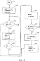
図5は、本発明のビデオ監視装置の操作方法を示すフローチャートである。
詳細な説明
以下は本発明の詳細な説明である。本発明は説明を目的とするものであり、本発明を制限するものではない。本発明の範囲は添付した請求の範囲により決定される。
図1に示すビデオカメラ監視装置は、A/D色空間変換回路20、パン−チルト−ズーム(PTZ)装置18、ユーザインタフェース32を備えた制御パネル30、制御翻訳回路40(関連メモリを備える適切にプログラムされたマイクロプロセッサ)、及び圧縮装置50を内蔵する。カメラ10は、映像信号19(画素から成る画像から構成)を発生し、色空間変換回路20に供給して、続いて、出力52からデジタル色差信号Cr,Cbと輝度信号Yを出力する。カメラ10は焦点調整機構14とズーム調整機構16とを備えるズームレンズ12を装着している。PTZ機構18は、制御パネル30から命令を入力してカメラ10のパン、チルト、ズームができるようにする。制御パネル30と制御翻訳回路40は、好ましくは、Florida州Deerfield BeachのSensormatic Electronics社から「Touchtracker」の名称で販売されている単一プロセッサベースの装置に装備されている。関連するレンズ、PTZ装置18、色空間変換回路20を内蔵するカメラ10は、好ましくは、Sensormatic Electronics社から「SpeedDome」の名称で販売されているセルフコンテイン式の「ドーム(dome)」内に収容されている。
圧縮装置50は、好ましくは、MPEG規格で説明したような周知のMPEG装置を用いた圧縮アルゴリズムを実行するハードウェアとソフトウェアを搭載する従来のビデオ圧縮装置である。MPEG規格は、ある程度の圧縮(空間領域と時間領域圧縮を含む)を行なう装置を対象としている。圧縮率が異なるあらゆる圧縮装置を用いることができる。例えば、フィルタ長、フィルタ係数、またはフィルタ形状を調整して空間領域圧縮率を変更する圧縮フィルタ(あらかじめ定められたフィルタ長、形状、係数を持つ)を備える周知の装置を使用することができ、これらは圧縮装置50により表されるものと同等と考えられる。ビデオ圧縮ハードウェアとソフトウェアは当業者に周知であるので、本発明に密接な関連がある局面のみを説明する。
圧縮装置50は、デジタル化された色差信号Cr,Cbと輝度信号Yを受け取る色空間変換回路20の出力52に接続した入力53を備えている。また、圧縮装置は出力54から制御翻訳回路40が生成した動きベクトルを受け取る入力55も備えている。これらの動きベクトルの生成と目的を以下に説明する。圧縮装置50の入力57から、制御翻訳回路40の出力56からの空間領域圧縮率に関する命令を受け取る。この詳細も以下に説明する。圧縮装置50は、通信チャネルを通して送信するために、圧縮した映像信号をマルチプレクサ80に出力する出力58を備えている。
好ましい圧縮装置の基本構成要素は以下の通りである。すなわち、減算器60、離散コサイン変換器62、量子化器64、可変長符号化器66、逆量子化器68、離散コサイン逆変換器70、加算器72、画像蓄積予測器74。量子化器64は、離散コサイン変換器62から供給された離散コサイン変換信号を量子化する。供給された信号の空間領域圧縮率は量子化器64で可変可能である。そのため、量子化器64は少なくとも2つの量子化マトリックスを有し、各マトリックスは異なる比率で空間領域圧縮を行なう。入力57からレジスタ65に変数を書き込むと、量子化マトリックスの1つが選択される。これらのすべての構成要素は当業者に周知であり、MPEGの参考書に詳しく記載されている。
上記に検討したように、MPEG規格だけでなく他の圧縮方式も空間領域と時間領域圧縮の2つの圧縮モードから成る。空間領域圧縮モードにおいて、圧縮装置50は、ビデオカメラ10が生成したビデオフレーム情報を圧縮する。各ビデオフレームは非常に多くの画素から成る画像を運ぶ。時間領域圧縮モードにおいて、動きベクトルはフレーム間の画像の変化を表すために生成される。従って、動きベクトルはビデオフレームによって運ばれる画像の動きを示す。
カメラ10が静止しているときは、映像信号のフレーム間の差は、カメラがパン、チルト、ズーム、ピント合わせしたときと比べ少ない。さらに、カメラが固定されていると、人間の目はカメラが移動中のときに比べ画像の細部まで詳しく識別できる。それゆえ、圧縮動作はカメラが移動中のときより固定しているときの方が各フレームの細部まで圧縮しなければならない。すなわち、カメラが固定されているとき、空間領域圧縮率は小さくなければならない。ここで説明した好ましい圧縮装置の場合、このことは粗い量子化に対応する。
カメラが移動中であるときや、ズームまたはピント合わせの際は、信号を正確に再生するため圧縮動作で画像の変化方法に関するより多くの情報を運ばなければならない。このため、カメラが固定しているときより大きな帯域幅が必要である。空間領域圧縮率を大きくすると(空間領域の量子化ステップを細かくすると)、パン、チルト、ズーム、ピント合わせに応じて時間領域圧縮(動きベクトルの生成)帯域を解放する。しかし、この方法は圧縮した信号を再生したとき細部が正確に再現されない。それにもかかわらず、これは受け入れ可能な解決策といえる。なぜなら、人間の目は静止している物体より移動している物体の細部を識別できないからである。
カメラ10が固定していてピント合わせされているときで、レンズ12をズームしないときは、制御翻訳回路40は時間領域圧縮を行なわない(動きベクトルを生成しない)。空間領域圧縮率は小さい。すなわち、適切な値をレジスタ65に書き込んで、量子化ステップの粗い量子化マトリックスが選択される。こうして、高精細な細部まで量子化した圧縮信号が出力58から出力される。
圧縮装置50の入力53に供給される出力52からの映像信号は制御翻訳回路40で設定される空間領域圧縮率に基づいて、MPEGアルゴリズムにより圧縮され、圧縮映像信号として出力58から出力される。この信号はマルチプレクサ80から出力82に渡され、通信チャネルを通して送信されるか、蓄積装置に蓄積される。
制御パネル30、制御翻訳回路40、PTZ装置18がカメラ制御装置を構成する。ユーザがユーザ入力32を用いて、カメラ10にパン、チルト、ズームまたはピントを合わせるように命令すると、制御パネル30が出力31から制御信号を出力する。制御信号は制御翻訳回路40の入力41に供給される。応答時に、制御翻訳回路40は補正指示信号を発生して、出力42から出力しPTZ装置18の入力43に供給して、カメラ10をパン、チルト、ズーム、ピント合わせを行なう。補正指示信号に応答して、制御翻訳回路40は一連の動きベクトルを生成する。動きベクトルは、カメラ10で生成される画像がユーザから受け取った命令でどのように変化するか表す。動きベクトルは、MPEG規格で規定された形式で出力され、時間領域圧縮を行なう。動きベクトルは、制御翻訳回路40のメモリのルックアップテーブルに格納される。このため、任意の特定のパン、チルト、ズーム、ピント合わせを行なう場合は、ルックアップテーブルに特定の動きベクトル対が蓄積される。パン、チルト、ズーム、ピント合わせ操作の合成を示すベクトルは、ある程度のパン、チルト、ズーム、ピント合わせに関連する各ベクトルを互いに乗算することにより求めることができる。動きベクトルはマルチプレクサ80に送られ、空間領域圧縮の結果として生成された圧縮信号と多重化される。
カメラ制御装置がカメラ10を補正(パン、チルト、ズーム、ピント合わせ)するとき、制御翻訳回路40が圧縮装置に命令を出力して、空間領域圧縮率を増加させる。好適な実施例において、制御翻訳回路は、量子化器64に命令を出力して量子化マトリックスを選択し、高次の空間領域圧縮を行ない適切な値をレジスタ65に書き込んで量子化ステップを細かくする。パン、チルト、ズーム、ピント合わせを増加または減少させると、制御翻訳回路40は圧縮装置40に命令を出力し空間領域圧縮率を適当な比率で増加または減少させる。こうして、カメラをその周囲に対して移動またはズームやピント合わせすると、圧縮動作は各フレームの細部に対して(空間領域圧縮)ではなく、画像フレーム間の変化(時間領域圧縮)に対し重み付けされる。
パン、チルト、ズーム、ピント合わせを停止すると、制御翻訳回路40は動きベクトルの生成を停止する。また、空間領域圧縮率を適切な低いレベルに調整する。
ここで説明した装置により、ビデオカメラの補正に応じて圧縮率を変更できる。これにより、カメラがパン、チルト、ズーム、ピント合わせしているかどうかについての知識に基づいて空間領域圧縮と時間領域圧縮率のトレードオフを図ることができる。MPEG圧縮装置の量子化ステップを調整して、空間領域圧縮率を変更する装置を参考にして装置を説明したが、当業者であれば本発明の好適な実施例の原理は、異なる圧縮方式を採用している装置にも同じように適用可能で、圧縮レベルを変更できることがわかるであろう。
この装置はカメラ10が生成した画像を蓄積する機能も備えている。圧縮率を変更する命令は、ビデオカセットレコーダ90に供給され、映像信号のフレーム間のビデオテープに記録される。すなわち、制御翻訳回路50および/または動きベクトルからの命令出力はビデオテープに記録される。従って、ビデオテープを圧縮装置50で再生したとき、空間および/または時間領域圧縮率と動きベクトルを変更する命令は記録された信号から抽出され、上述したように用いられる。
図2に示す本発明の第2実施例で、補正指示信号は、制御パネルで発生された制御信号によってではなく、パン、チルト、ズーム、ピント合わせの状態を検出するトランスジューサで発生される。トランスジューサ118はカメラ10のパンの状態を検出して、出力119からパン補正信号を出力する。またトランスジューサ120は、カメラ10のチルト状態を検出して、出力121からチルト補正信号を出力する。さらにトランスジューサ114は、レンズ12のズーム状態を検出して、出力115からズーム指示信号を出力する。またさらにトランスジューサ116は、レンズ12のピント合わせの状態を検出して、出力117からピント合わせ信号を出力する。トランスジューサ114,116,118,120が、出力115,117,119,121からそれぞれ出力した信号は処理装置の入力125,127,129,132にそれぞれ供給される。処理装置140は出力154,156を生成する。これらの出力は上述した出力54,56と同じで、同じように用いられる。
図3に示すものは本発明の第3実施例である。第3実施例は、簡略化した高精度動き推定回路90を内蔵している点を除き、第1実施例と同じである。この装置はMPEG規格で説明した従来の動き推定回路と全く同じである。動き推定回路90は入力91から色空間変換回路20が発生した信号を受け取る。動き推定回路はMPEG規格に準拠して出力92,93において合成動きベクトルを生成する。これらの動きベクトルは制御翻訳回路40で生成された動きベクトルと乗算され、より簡単な動きベクトルを生成する。
上述した装置は、遠方からの監視が可能なビデオ監視装置の一部である。以下はこの装置の説明である。
上述した装置を内蔵するビデオ監視装置210は図4にブロック図で示されている。以下に説明する監視装置は本発明の第1実施例を内蔵している(図1)。しかし、以下の説明により、当業者は第1、第2、第3実施例を内蔵する監視装置を製作することができるだろう。
装置210は監視局220とビデオカメラモジュール240とから構成されている。監視局220は、公衆通信交換網280を介してビデオカメラモジュール240と通信する。公衆通信交換網280は地方の電話局が管理する標準的な電話網が好ましい。公衆通信交換網280は、例えば、光ファイバ網、携帯電話網、ethernetや部分的なISDN網などのローカルエリアネットワークでもよい。
この装置210を1つの監視局と1つのカメラモジュールだけを用いて説明したが、公衆通信交換網の回線交換機能を用いた公衆通信交換網を通して複数の監視局とカメラモジュールを接続できる。
ビデオカメラ242を装備したビデオカメラモジュール240は監視局220から離れた場所に設置されている、例えば、カメラモジュールは、町のさまざまな位置のいくつかの店の1つに設置される。本発明により、すべてのカメラモジュールを公衆電話網を通して中央監視局から監視できる。大きな空港にも装置210が設置され得る。辺鄙な場所の建物であれば中央局から監視することもできる。辺鄙な場所では、電話網を通し中央監視局に接続する傾向があるが、その際、本発明を用いると監視局へのビデオカメラモジュールの接続に追加配線は必要ない。
監視局220は、公衆通信交換網280へ監視局を接続するネットワークインタフェース222を備えている。ネットワークインタフェース222は、電話回線インタフェース223と通信ハードウェア224(ISDN基本速度インタフェースまたはモデムに内蔵)から成る。
本発明を搭載した公衆通信交換網は、通常28000〜128000ビット/秒の速度で動作する。しかし、ビデオデータは、通常約80000000ビット/秒の通信速度を必要とする。カメラ242で撮影したビデオデータは、上述した圧縮装置によりカメラモジュール240で圧縮される。そして、信号処理装置226は、カメラモジュール240から受け取った圧縮画像信号を伸長(解凍)する。ネットワークインタフェース222と伸長回路226は、マイクロプロセッサ228、例えばMotorola社の68030、Intel社の486または同等のマイクロプロセッサにより制御される。監視局220はビデオモニタ230を内蔵している。マイクロプロセッサ228は監視局220全体の動作を制御する。制御信号を送るには、マイクロプロセッサ228とネットワークインタフェース222とをデータバス236で接続する。キーボード232、マウス、トラックボール入力装置234(Florida州Deerfield BeachのSensormatic Electronics社から入手可能なTouchtrackerカメラコントローラが好ましい)などのユーザインタフェースを装備し、マイクロプロセッサ228が公衆通信交換網280を通してビデオカメラモジュール240に送信する命令をオペレータが入力できるようにする。このように、カメラモジュール240のあらゆる動作を遠方から制御するため、命令を監視局220からカメラモジュール240に送ることができる。例えば、ユーザはカメラ242にパン、チルト、ズーム、ピントを合わせを行なうように命令をすることができる。従って、キーボード232と入力装置234は、図1について上述した制御パネル30とユーザ入力32の機能を実行する。このような機能を実行する装置は、同時係属中の米国特許出願第08/166,599号に開示されており、ここに参照として援用する。制御信号は、通信チャネル280を通してカメラモジュール240に送られる。
カメラモジュール240は、ある領域を監視するビデオ監視カメラ242、ビデオ圧縮装置246、ネットワークインタフェース250とを内蔵した一体型装置である。カメラ242は、ビデオ圧縮装置246に供給される画像信号244を発生する。圧縮装置246は、図1を参照して上述したビデオ圧縮装置50と同じである。ビデオ圧縮装置246は、California州Santa ClaraのIntegrated Information Technology社からVision Controller/Vision Processorの名称で販売されているもの、または同等の圧縮回路が好ましい。ビデオ圧縮装置は、上述したデータマルチプレクサ80を内蔵している。処理された信号は248は、カメラ242を公衆通信交換網280に接続するネットワークインタフェース250に供給される。通信ハードウェア252とラインインタフェース254とから構成されるネットワークインタフェース250は、監視局220のネットワークインタフェース222と基本的に同じである。マイクロプロセッサ228と同じ型であってもよいマイクロプロセッサ256はカメラ242とネットワークインタフェース250の動作を制御する。データバス258は、マイクロプロセッサ256、カメラ242、ビデオ圧縮ハードウェア246、ネットワークインタフェース250との間で制御データを送る。マイクロプロセッサ228は、キーボード232、入力装置234、マイクロプロセッサ228が発生した制御信号を(通信チャネル280を介して)受け取る。マイクロプロセッサ256は、図1を参照して上述した制御翻訳回路40の機能を実行するようにプログラムされている。すなわち、マイクロプロセッサ228は、受け取る制御信号をカメラ補正指示信号に変換し、これはデータバス258を通してカメラ242に送られる。圧縮パラメータの変更を要求する圧縮装置246への命令は、カメラ補正指示信号に応答してマイクロプロセッサ256で生成され、データバス258を介して圧縮装置246の適切なピンに供給される。同様に、動きベクトルもマイクロプロセッサ256によるカメラ補正指示信号に応答して生成され、圧縮装置246に供給されて多重化される。
カメラモジュール240は、ディスクドライブまたはランダムアクセスメモリから成るデジタル・ファーストイン・ファーストアウト(FIFO)メモリ266によるメモリ機能を搭載している。メモリ266は所定の時間、例えば3分間にわたり処理した画像信号248を蓄積する。それゆえ、メモリ266は、カメラ242が以前の所定の時間にわたって取得した記録を継続的に保持する。メモリ266は、データバス258によりマイクロプロセッサ256に接続されている。ビデオカセットレコーダ(VCR)ディスクやランダムアクセスメモリなどの蓄積装置270が、カメラ242の出力を蓄積し、圧縮装置246で再生できるように、カメラ242と圧縮装置246に接続されている。この実施例で、制御翻訳回路40の出力54と56はカメラ242の出力と共に蓄積される。代わりに、圧縮して蓄積されるように、データを圧縮装置246から蓄積装置270に供給できる。蓄積装置270は、さまざまなものを用いることができる。これらのいくつかを以下に説明する。蓄積装置270の動作は、データバス258を介してマイクロプロセッサ256から制御できる。電子的に制御可能なVCR、例えばPanasonic AG-6730を用いることができる。
カメラモジュール240は、カメラ242から出力される画像信号244を解析して、カメラ242の監視被写体が動いたかどうか検出する動き検出回路260を内蔵している。動き検出回路は、データバス258によりマイクロプロセッサ256に接続されている。カメラモジュール240には、マイクロプロセッサ256に接続されたアラーム装置インタフェース268が装備されている。アラーム装置インタフェースは、マイクロプロセッサ256がさまざまな種類のアラーム受信を容易にできるようにし、これにより、メモリ266や蓄積装置270への蓄積、あるいは公衆通信交換網280を通した送信を開始する。動き検出器260が被写体の動きを検出、またはアラームインタフェース268を介してアラーム信号を受け取った場合、信号262を発生してマイクロプロセッサ256に送る。マイクロプロセッサ256は、信号262に応答して開始信号264を発生し、これにより第2インタフェース250に公衆通信交換網280を介して信号処理装置246が処理した画像の送信を開始させる。
アラームや動き検出信号262が発生した信号をマイクロプロセッサ256が受け取ると、マイクロプロセッサ256が各種動作を開始できる。例えば、マイクロプロセッサは、蓄積装置270への蓄積の開始、経過時間から実時間への記録モードの変更、カメラ242の出力を圧縮して公衆通信交換網280を通して送信するか、メモリ266や蓄積装置270の内容を公衆通信交換網280に出力するように命令できる。これらはすべてマイクロプロセッサ256のプログラミング方法とシステム構成に左右される。開始信号264も監視局220から送信できる。
公衆通信交換網280が公衆電話通信網である好適な実施例で、カメラモジュール240と監視局220はそれぞれ自分自身の電話番号を持っている。ラインインタフェース223,254は互いに、または公衆通信交換網280に接続された他のモジュールを呼び出して通信を開始できる。従って、例えば、マイクロプロセッサ256が上述したように開始信号を発生すると(例えば、動き検出に応答して)、カメラモジュール240のラインインタフェース254は監視局220を呼び出す。呼は監視局220のラインインタフェース223で受け取られる。次いで、カメラモジュール240と監視局220との間でハンドシェーキングを開始すると、インタフェース250からの圧縮ビデオデータをインタフェース222が受け取る。伸長回路226が受け取った圧縮データをモニタ230に表示できるように、伸長(解凍)する。
同様に、ユーザまたはアラームが発生した開始信号に応答して、マイクロプロセッサ228が、監視局220からカメラモジュール240を呼び出して通信を開始し、カメラ242、蓄積装置270、メモリ266からデータを受け取る。カメラモジュール240の各構成要素の動作は、いったんカメラモジュールと監視局との間で通信を確立すると、監視局230から制御できる。
本発明は2つのモードで好適に動作できる。第1のモードで、監視局220は第1のネットワークインタフェース222を用いて、カメラモジュール240を呼び出すことができる。その後、監視局220のユーザは、キーボード232または入力装置234を用いて遠方からカメラモジュール240の動作を制御できる。例えば、ユーザはカメラモジュール240に命令を出力してメモリ266の内容を出力させ、蓄積装置270の内容を再生やカメラモジュール240の内容を単にリアルタイムで監視する。第2のモードで、カメラモジュール240は監視局220を呼び出す。例えば、カメラモジュール240で検出したアラームイベントは、監視局220への呼び出しを開始することができる。次いで、カメラモジュール240は、カメラ242で取得した生データを送信して、FIFO266または蓄積装置270の内容を再生する。
図5は、好ましい操作方法のフローチャートである。図5に記載した方法のステップは、「S」を前に付けた番号で示される。図5の方法で、カメラモジュール240の動作は、カメラモジュール240の電源を投入し、ビデオ圧縮ハードウェア246を初期化して開始する(ステップS1とS2)。圧縮装置246の初期化には、圧縮装置256のRISCプロセッサへの命令コードへのダウンロードだけでなく、圧縮プロセスのデータレートと初期量子化パラメータなどのダウンロードが含まれる。マイクロプロセッサ256は、アラームインタフェース268と動き検出器260を常時監視する(S3)。例えば、ドアの開放や、動きのアラーム条件が検出された場合、マイクロプロセッサ256は、データバス258を介して蓄積装置270に命令を送出して、蓄積を開始し、マイクロプロセッサ内のタイマーを設定する(S4)。蓄積は所定の期間T1の間続く(S5)。T1の最後で、マイクロプロセッサ256は、通信ハードウェア252に命令を出力して、公衆通信交換網280を通して監視局220を呼び出す(S6)。呼び出しが成功するまで規定回数呼び出しを続ける(S7)。呼び出しが成功すると、マイクロプロセッサ256は、蓄積装置270に命令を出力してちょうど蓄積したばかりの情報を圧縮装置246に出力させる。代わりに、この情報が蓄積装置270に圧縮して蓄積されていればこのステップをバイパスできる。マイクロプロセッサ256は、通信ハードウェア252に命令を出力して、公衆通信交換網280を介して監視局220に圧縮装置246の圧縮した出力を送信する。圧縮データは伸長装置226で伸長され、蓄積装置270に蓄積された画像がモニタ230に表示される。
上述した方法で、メモリ266を蓄積装置270に置き換えることができる。代わりに、監視局220へ記録情報を送信する代わりに、マイクロプロセッサ256は、カメラ242のリアルタイム出力を公衆通信交換網280を通し圧縮して送信できる。代わりに、カメラ242のビデオデータ出力は、Tに等しい期間の間メモリ266に連続的に蓄積できる。従って、所定の時間で、前のT秒の間のビデオデータはメモリ266に蓄積される。トリガー条件が発生し、監視局220を呼び出したとき、すぐ前のT秒の間に蓄積された圧縮ビデオデータがメモリ266から出力され、監視局220へ送信される。これにより、監視モジュールは、トリガーイベントのすぐ前で発生したことに関する情報を得ることができる。メモリ266を用いる代わりに、所定の時間で、ビデオカメラ242の出力が蓄積されるように、蓄積装置270に加え第2のスタンバイ蓄積装置を追加できる。すなわち、1つの蓄積装置がいっぱいになると、他の蓄積装置が蓄積を開始して、第1の蓄積装置は第2の蓄積装置がいっぱいになるのを待つ。代わりに、規定の間隔でサンプルされたビデオデータをメモリ266に蓄積することもできる。 Background
The present invention relates generally to the field of video compression. In particular, the present invention relates to an apparatus for optimizing the use of resources for compressing video signals generated by a video camera using video camera correction knowledge.
Video surveillance cameras are widely used for surveillance purposes in building safety management. It is common to place one or more video cameras at various locations to monitor. The output of the camera is displayed or recorded at the central office. It is also possible to distribute a large number of cameras at locations away from the central office. For example, cameras may be installed in stores at various points in the city and monitored from the central office. A remote control camera can be installed at a location away from the airport center and monitored from the central office.
In such a device, it is necessary to send information collected by the video camera to a central monitoring station. For this reason, it may be desirable to compress the video data so that it can be transmitted over a communication channel having a relatively narrow bandwidth.
Known video compression devices are equipped with two basic schemes: spatial domain and temporal domain compression. Spatial domain compression compresses information by transmitting pixels of a specific frame of a video signal using a compression algorithm, thereby reducing the amount of information necessary for frame reproduction. In contrast, time domain compression utilizes the fact that information changes with time. Therefore, time domain compression reduces the amount of information required for frame playback by utilizing image changes that occur between frames. These changes are reflected in the motion vectors generated and transmitted instead of the actual content of the video frame. A description of the realization of space domain and time domain compression is published in MPEG recommendation ISO / IEC1172-2 (herein referred to as the MPEG standard).
The MPEG standard is one of several well-known standards for video processing. The conventional MPEG encoder can change the compression ratio of the spatial domain, for example, to adjust the quantization step of the information amount of a specific frame to save memory. Such an encoder also has a function (motion vector correction) of detecting the motion of an image between frames and adjusting the compression ratio of the spatial domain.
In a scene monitored by a video camera, movement can occur as a result of subject movement (eg, a person crossing the camera's field of view) or camera movement (due to camera pan, tilt, zoom, or focus). is there. As the image moves, movement information must be extracted to generate a motion vector. Conventional devices that perform time domain compression to transmit information (eg, using an MPEG compression scheme) require relatively large memory space and computational speed.
The present invention relates to the computation and memory overhead reduction required to compress video data using known information about image motion caused by camera movement. In particular, the present invention corrects using information generated from the correction result of the camera to achieve a trade-off between time domain compression and space domain compression. Rather than extracting information from the image, the information is obtained from the means that actually controls the camera.
Summary of invention
The present invention relates to a video camera apparatus that performs compression processing and a method used in the apparatus. This device is equipped with a correctable video camera. The camera generates a video signal composed of a plurality of images. The compression rate of the video signal is determined by the compression means, and a compressed video signal is generated. The camera control device corrects the video camera. The camera control device has a built-in means for generating a correction instruction signal indicating the correction of the video camera by the camera control device. In response to the correction instruction signal generated by the control device, the processing circuit outputs a command for changing the compression rate to the compression means. The knowledge of camera correction obtained from this control device is used to change the compression ratio.
[Brief description of the drawings]
FIG. 1 is a block diagram of a first embodiment of the video camera apparatus of the present invention.
FIG. 2 is a block diagram of a second embodiment of the video camera apparatus of the present invention.
FIG. 3 is a block diagram of a third embodiment of the video camera apparatus of the present invention.
FIG. 4 is a block diagram of the video surveillance apparatus of the present invention.
FIG. 5 is a flowchart showing the operation method of the video surveillance apparatus of the present invention.
Detailed description
The following is a detailed description of the invention. The present invention is intended to be illustrative and not limiting. The scope of the invention is determined by the appended claims.
The video camera monitoring device shown in FIG. 1 includes an A / D color
The
The
The basic components of a preferred compression device are as follows. That is, a
As discussed above, not only the MPEG standard but also other compression schemes consist of two compression modes: spatial domain and temporal domain compression. In the spatial domain compression mode, the
When the
When the camera is moving, or when zooming or focusing, more information about how the image changes must be carried in the compression operation to accurately reproduce the signal. This requires a larger bandwidth than when the camera is fixed. Increasing the spatial domain compression ratio (decreasing the spatial domain quantization step) releases the time domain compression (motion vector generation) band according to pan, tilt, zoom, and focus. However, this method does not accurately reproduce details when the compressed signal is reproduced. Nevertheless, this is an acceptable solution. This is because the human eye cannot distinguish the details of a moving object from a stationary object.
When the
The video signal from the
The
When the camera control device corrects the camera 10 (pan, tilt, zoom, focus), the
When panning, tilting, zooming, and focusing are stopped, the
With the apparatus described here, the compression rate can be changed according to the correction of the video camera. This makes it possible to trade-off between space domain compression and time domain compression based on knowledge about whether the camera is panning, tilting, zooming, and focusing. Although the apparatus has been described with reference to an apparatus for adjusting the quantization step of the MPEG compression apparatus and changing the space domain compression ratio, those skilled in the art will understand that the principle of the preferred embodiment of the present invention is to use different compression methods. It will be appreciated that the apparatus employed is equally applicable and the compression level can be changed.
This apparatus also has a function of accumulating images generated by the
In the second embodiment of the present invention shown in FIG. 2, the correction instruction signal is generated not by a control signal generated by the control panel but by a transducer that detects pan, tilt, zoom, and focus states. The
FIG. 3 shows a third embodiment of the present invention. The third embodiment is the same as the first embodiment except that a simplified high-precision
The devices described above are part of video surveillance devices that can be monitored from a distance. The following is a description of this device.
A
The
Although the
A
The
A public switched network equipped with the present invention normally operates at a speed of 28000-128000 bits / second. However, video data usually requires a communication speed of about 80000000 bits / second. Video data photographed by the
The
The
The
When the
In the preferred embodiment where the public switched
Similarly, in response to a user or alarm start signal, the
The present invention can preferably operate in two modes. In the first mode, the
FIG. 5 is a flowchart of a preferred operating method. The steps of the method described in FIG. 5 are indicated by a number prefixed with “S”. In the method of FIG. 5, the operation of the
The
Claims (34)
ビデオカメラのパン、チルト、ズーム、またはピントを調節するカメラ制御装置であり、前記カメラ制御装置は、カメラ制御装置によるビデオカメラのパン、チルト、ズーム、またはピントを調節する信号を示す補正指示信号を発生する手段を備えるカメラ制御装置と、
映像信号を所定の圧縮率で圧縮する圧縮手段であり、前記圧縮手段が、補正指示信号に応答して動きベクトルを生成するための手段を含み、映像信号の空間領域を所定の圧縮率で圧縮する手段と、映像信号の時間領域を所定の圧縮率で圧縮する手段とを備え、
前記補正指示信号に応答して圧縮率を変更する命令を前記圧縮手段に出力する処理装置であり、前記圧縮率を変更する命令が、前記補正指示信号に応答して空間領域の圧縮率と時間領域の圧縮率を変更する命令である処理装置
とを備えるビデオカメラ装置。A video camera that attaches a lens and generates a video signal composed of a plurality of images;
A camera control device that adjusts pan, tilt, zoom, or focus of a video camera, and the camera control device indicates a correction instruction signal indicating a signal for adjusting pan, tilt, zoom, or focus of the video camera by the camera control device A camera control device comprising means for generating
Compression means for compressing a video signal at a predetermined compression rate, the compression means including means for generating a motion vector in response to a correction instruction signal, and compressing a spatial region of the video signal at a predetermined compression rate Means for compressing the time domain of the video signal at a predetermined compression rate,
A processing device that outputs a command for changing a compression rate in response to the correction instruction signal to the compression unit, and the command for changing the compression rate is a compression rate and a time of a spatial region in response to the correction instruction signal. A video camera apparatus comprising: a processing device that is an instruction to change a compression rate of an area.
請求項1のビデオカメラ装置。The means for achieving the compression ratio of the spatial domain includes a quantizer that quantizes the video signal at a predetermined quantization rate, and the command for changing the compression ratio of the spatial domain in response to the correction instruction signal includes: 2. The video camera apparatus according to claim 1, further comprising: an instruction to be performed on the compression means for changing the quantization rate of the video signal by the quantizer.
映像信号を発生するビデオカメラと、
ビデオカメラモジュールを通信網に接続して、前記ビデオカメラモジュールが通信網を通して監視局と通信できるように、ビデオカメラモジュールを通信網に接続する第1のネットワークインタフェースと、
ビデオカメラのパン、チルト、ズーム、またはピントを調節するカメラ制御装置であり、前記カメラ制御装置は、カメラ制御装置によるビデオカメラのパン、チルト、ズーム、またはピントを調節する信号を示す補正指示信号を発生する手段を備えるカメラ制御装置と、
映像信号を所定の圧縮率で圧縮する圧縮手段であり、前記圧縮手段が、補正指示信号に応答して動きベクトルを生成するための手段を含み、映像信号の空間領域を所定の圧縮率で圧縮する手段と、映像信号の時間領域を所定の圧縮率で圧縮する手段とを備え、
前記補正指示信号に応答して圧縮率を変更する命令を前記圧縮手段に出力する処理装置であり、前記圧縮率を変更する命令が、前記補正指示信号に応答して空間領域の圧縮率と時間領域の圧縮率を変更する命令である処理装置
とを備える遠方を監視するビデオ監視装置。A remote video camera monitoring module,
A video camera that generates a video signal;
A first network interface for connecting the video camera module to the communication network so that the video camera module is connected to the communication network so that the video camera module can communicate with the monitoring station through the communication network;
A camera control device that adjusts pan, tilt, zoom, or focus of a video camera, and the camera control device indicates a correction instruction signal indicating a signal for adjusting pan, tilt, zoom, or focus of the video camera by the camera control device A camera control device comprising means for generating
Compression means for compressing a video signal at a predetermined compression rate, the compression means including means for generating a motion vector in response to a correction instruction signal, and compressing a spatial region of the video signal at a predetermined compression rate Means for compressing the time domain of the video signal at a predetermined compression rate,
A processing device that outputs a command for changing a compression rate in response to the correction instruction signal to the compression unit, and the command for changing the compression rate is a compression rate and a time of a spatial region in response to the correction instruction signal. A video surveillance apparatus for monitoring a remote location, comprising: a processing device that is a command for changing a compression ratio of a region.
ビデオカメラのパン、チルト、ズーム、またはピントを調節するカメラ制御装置であり、前記カメラ制御装置は、カメラ制御装置によるビデオカメラのパン、チルト、ズーム、またはピントを調節する信号を示す補正指示信号を発生する手段を備えるカメラ制御装置と、
映像信号を所定の圧縮率で圧縮する圧縮手段であり、前記圧縮手段が、補正指示信号に応答して動きベクトルを生成するための手段を含み、映像信号の空間領域を所定の圧縮率で圧縮する手段と、映像信号の時間領域を所定の圧縮率で圧縮する手段とを備え、
前記補正指示信号に応答して圧縮率を変更する命令を前記圧縮手段に出力する処理装置であり、前記圧縮率を変更する命令が、前記補正指示信号に応答して空間領域の圧縮率と時間領域の圧縮率を変更する命令である処理装置と、
蓄積媒体に映像信号を蓄積し、圧縮率を変更する命令を前記蓄積媒体に蓄積する手段
とを備えるビデオカメラ装置。A video camera that attaches a lens and generates a video signal composed of a plurality of images;
A camera control device that adjusts pan, tilt, zoom, or focus of a video camera, and the camera control device indicates a correction instruction signal indicating a signal for adjusting pan, tilt, zoom, or focus of the video camera by the camera control device A camera control device comprising means for generating
Compression means for compressing a video signal at a predetermined compression rate, the compression means including means for generating a motion vector in response to a correction instruction signal, and compressing a spatial region of the video signal at a predetermined compression rate Means for compressing the time domain of the video signal at a predetermined compression rate,
A processing device that outputs a command for changing a compression rate in response to the correction instruction signal to the compression unit, and the command for changing the compression rate is a compression rate and a time of a spatial region in response to the correction instruction signal. A processor that is an instruction to change the compression ratio of the area;
A video camera apparatus comprising: means for storing a video signal in a storage medium and storing a command for changing a compression rate in the storage medium.
前記ビデオカメラのパン、チルト、ズーム、またはピントの調節を行い、前記ビデオカメラのパン、チルト、ズーム、またはピントを調節する信号を示す補正指示信号を発生するステップと、
映像信号を所定の圧縮率で圧縮するステップであり、前記映像信号を所定の圧縮率で圧縮するステップが、補正指示信号に応答して動きベクトルを生成するためのステップを含み、映像信号の空間領域を所定の圧縮率で圧縮するステップと、映像信号の時間領域を所定の圧縮率で圧縮するステップとを備え、
前記補正指示信号に応答して圧縮率を変更する命令を圧縮手段に出力するステップであり、前記圧縮率を変更する命令が、前記補正指示信号に応答して空間領域の圧縮率と時間領域の圧縮率を変更する命令であるステップと、
を含む、調節可能なビデオカメラとビデオカメラのパン、チルト、ズーム、またはピントの調節を行なうコントローラとを備えるビデオカメラ装置に用いる映像信号の圧縮方法。Generating a video signal comprising a plurality of images;
Adjusting the pan, tilt, zoom, or focus of the video camera and generating a correction instruction signal indicating a signal for adjusting the pan, tilt, zoom, or focus of the video camera;
A step of compressing the video signal at a predetermined compression rate, wherein the step of compressing the video signal at a predetermined compression rate includes a step of generating a motion vector in response to the correction instruction signal, Compressing the region at a predetermined compression rate, and compressing the time region of the video signal at a predetermined compression rate,
Outputting a command for changing the compression ratio in response to the correction instruction signal to the compression means, wherein the command for changing the compression ratio is a response to the correction instruction signal in the compression ratio of the space region and the time domain. A step that is an instruction to change the compression rate; and
A video signal compression method for use in a video camera apparatus, comprising: an adjustable video camera and a controller that adjusts pan, tilt, zoom, or focus of the video camera.
ビデオカメラのパン、チルト、ズーム、またはピントを調節するカメラ制御装置であり、前記カメラ制御装置は、ビデオカメラのパン、チルト、ズーム、またはピントを調節する制御信号を発生させる手段を含むリモートコントローラと、前記制御信号を受け取り、受け取った制御信号に応答してカメラ制御装置によってビデオカメラのパン、チルト、ズーム、またはピントを調節する信号を示す補正指示信号を発生する手段を備え、
映像信号を所定の圧縮率で圧縮する圧縮手段であり、前記圧縮手段が、補正指示信号に応答して動きベクトルを生成するための手段を含み、映像信号の空間領域を所定の圧縮率で圧縮する手段と、映像信号の時間領域を所定の圧縮率で圧縮する手段とを備え、
前記補正指示信号に応答して圧縮率を変更する命令を前記圧縮手段に出力する処理装置であり、前記圧縮率を変更する命令が、前記補正指示信号に応答して空間領域の圧縮率と時間領域の圧縮率を変更する命令である処理装置とを備えるビデオカメラ装置。A video camera that attaches a lens and generates a video signal composed of a plurality of images;
A camera control device for adjusting pan, tilt, zoom, or focus of a video camera, wherein the camera control device includes means for generating a control signal for adjusting pan, tilt, zoom, or focus of the video camera And means for receiving the control signal and generating a correction instruction signal indicating a signal for adjusting pan, tilt, zoom, or focus of the video camera by the camera control device in response to the received control signal,
Compression means for compressing a video signal at a predetermined compression rate, the compression means including means for generating a motion vector in response to a correction instruction signal, and compressing a spatial region of the video signal at a predetermined compression rate Means for compressing the time domain of the video signal at a predetermined compression rate,
A processing device that outputs a command for changing a compression rate in response to the correction instruction signal to the compression unit, and the command for changing the compression rate is a compression rate and a time of a spatial region in response to the correction instruction signal. A video camera apparatus comprising: a processing device that is an instruction to change a compression rate of an area.
Applications Claiming Priority (3)
| Application Number | Priority Date | Filing Date | Title |
|---|---|---|---|
| US08/502,576 US5926209A (en) | 1995-07-14 | 1995-04-14 | Video camera apparatus with compression system responsive to video camera adjustment |
| US08/502,576 | 1995-07-14 | ||
| PCT/US1996/011418 WO1997004597A1 (en) | 1995-07-14 | 1996-07-08 | Video compression system |
Publications (2)
| Publication Number | Publication Date |
|---|---|
| JPH11509701A JPH11509701A (en) | 1999-08-24 |
| JP4235259B2 true JP4235259B2 (en) | 2009-03-11 |
Family
ID=23998431
Family Applications (1)
| Application Number | Title | Priority Date | Filing Date |
|---|---|---|---|
| JP50671697A Expired - Lifetime JP4235259B2 (en) | 1995-07-14 | 1996-07-08 | Video compression equipment |
Country Status (10)
| Country | Link |
|---|---|
| US (1) | US5926209A (en) |
| EP (1) | EP0839430B1 (en) |
| JP (1) | JP4235259B2 (en) |
| KR (1) | KR19990028825A (en) |
| AR (1) | AR002822A1 (en) |
| AU (1) | AU716417B2 (en) |
| BR (1) | BR9609700A (en) |
| CA (1) | CA2226324C (en) |
| DE (1) | DE69630121T2 (en) |
| WO (1) | WO1997004597A1 (en) |
Families Citing this family (211)
| Publication number | Priority date | Publication date | Assignee | Title |
|---|---|---|---|---|
| US6314140B1 (en) * | 1995-12-28 | 2001-11-06 | Lucent Technologies Inc. | Dynamic video focus control |
| JPH09289631A (en) * | 1996-02-20 | 1997-11-04 | Canon Inc | Image pickup control method and device, image pickup system and storage medium storing program to execute the method |
| DE69738619T2 (en) * | 1996-07-23 | 2009-05-20 | Canon K.K. | Method and device for camera control |
| US6038289A (en) * | 1996-09-12 | 2000-03-14 | Simplex Time Recorder Co. | Redundant video alarm monitoring system |
| JP3592025B2 (en) * | 1997-03-11 | 2004-11-24 | キヤノン株式会社 | Captured image recording device |
| US6384862B1 (en) * | 1997-03-12 | 2002-05-07 | Telefoaktiebolaget L M Ericsson | Imaging system and method for interactive control of image quality |
| JP3217723B2 (en) * | 1997-03-13 | 2001-10-15 | ▲すすむ▼ 舘 | Telecommunications system and telecommunications method |
| JPH10322686A (en) * | 1997-05-15 | 1998-12-04 | Niles Parts Co Ltd | Door camera unit provided with image memory |
| JP3052893B2 (en) * | 1997-05-16 | 2000-06-19 | 日本電気株式会社 | Video encoding device |
| US8073921B2 (en) * | 1997-07-01 | 2011-12-06 | Advanced Technology Company, LLC | Methods for remote monitoring and control of appliances over a computer network |
| JPH1139495A (en) * | 1997-07-24 | 1999-02-12 | Nec Corp | Image supervisory device |
| US6618074B1 (en) * | 1997-08-01 | 2003-09-09 | Wells Fargo Alarm Systems, Inc. | Central alarm computer for video security system |
| US6069655A (en) * | 1997-08-01 | 2000-05-30 | Wells Fargo Alarm Services, Inc. | Advanced video security system |
| US6097429A (en) * | 1997-08-01 | 2000-08-01 | Esco Electronics Corporation | Site control unit for video security system |
| US6091771A (en) * | 1997-08-01 | 2000-07-18 | Wells Fargo Alarm Services, Inc. | Workstation for video security system |
| GB2328578A (en) * | 1997-08-22 | 1999-02-24 | Motion Media Techn Ltd | Automatic reset of remote video surveillance system |
| DE19744294C2 (en) * | 1997-10-07 | 1999-07-29 | Videocon Ag | Method and apparatus for monitoring a target area from a remote location |
| US7054916B2 (en) * | 1997-12-08 | 2006-05-30 | Sanyo Electric Co., Ltd. | Imaging apparatus and network system using the same |
| JP3649883B2 (en) * | 1997-12-08 | 2005-05-18 | 三洋電機株式会社 | Imaging apparatus and network system |
| SE9704589D0 (en) * | 1997-12-09 | 1997-12-09 | Alfa Laval Agri Ab | An apparatus and a method for monitoring an animal related space |
| JPH11239329A (en) * | 1998-02-23 | 1999-08-31 | Sony Corp | Image transmitter and image transmission system using the same |
| US6415094B1 (en) * | 1998-03-16 | 2002-07-02 | Charles H. Wissman | Method and apparatus for extending the recording time of a remotely controllable electronic device using a hand-held autonomous remote control |
| JPH11266487A (en) * | 1998-03-18 | 1999-09-28 | Toshiba Corp | Intelligent remote supervisory system and recording medium |
| US6512537B1 (en) * | 1998-06-03 | 2003-01-28 | Matsushita Electric Industrial Co., Ltd. | Motion detecting apparatus, motion detecting method, and storage medium storing motion detecting program for avoiding incorrect detection |
| US6421097B1 (en) * | 1998-07-31 | 2002-07-16 | Intel Corporation | Method and apparatus for reducing flicker in a video image sequence |
| US6590607B1 (en) * | 1998-08-19 | 2003-07-08 | Hewlett-Packard Development Company, L.P. | Method and apparatus for storing an uninterrupted digital video stream |
| US20020170064A1 (en) * | 2001-05-11 | 2002-11-14 | Monroe David A. | Portable, wireless monitoring and control station for use in connection with a multi-media surveillance system having enhanced notification functions |
| JP3976942B2 (en) * | 1998-12-18 | 2007-09-19 | キヤノン株式会社 | Image processing apparatus and method, and computer-readable recording medium on which an image processing program is recorded |
| JP2002535895A (en) * | 1999-01-15 | 2002-10-22 | コーニンクレッカ フィリップス エレクトロニクス エヌ ヴィ | Image sequence coding and noise filtering |
| GB2354656A (en) * | 1999-06-22 | 2001-03-28 | Snell & Wilcox Ltd | Electronic capture of moving images |
| US7015806B2 (en) * | 1999-07-20 | 2006-03-21 | @Security Broadband Corporation | Distributed monitoring for a video security system |
| US9300921B2 (en) | 1999-07-20 | 2016-03-29 | Comcast Cable Communications, Llc | Video security systems and methods |
| US6690411B2 (en) * | 1999-07-20 | 2004-02-10 | @Security Broadband Corp. | Security system |
| US8520068B2 (en) * | 1999-07-20 | 2013-08-27 | Comcast Cable Communications, Llc | Video security system |
| US6489989B1 (en) | 1999-09-15 | 2002-12-03 | Electric Planet, Inc. | System, method and article of manufacture for executing a video setup protocol |
| US7479980B2 (en) * | 1999-12-23 | 2009-01-20 | Wespot Technologies Ab | Monitoring system |
| US7012641B2 (en) * | 2000-02-14 | 2006-03-14 | Canon Kabushiki Kaisha | Image sensing apparatus, method, memory involving differential compression of display region based on zoom operation or speed |
| DE50014846D1 (en) * | 2000-02-22 | 2008-01-24 | Siemens Ag | Method for operating an image recording device and arrangement for carrying out the method |
| US6433683B1 (en) * | 2000-02-28 | 2002-08-13 | Carl Robinson | Multipurpose wireless video alarm device and system |
| DE10010590A1 (en) * | 2000-03-03 | 2001-09-13 | Nedret Sahin | Operating a remote-controlled camera, involves transmitting data from a remote control unit and camera to an image display device via a computer network |
| JP2001333415A (en) * | 2000-05-18 | 2001-11-30 | Sanyo Electric Co Ltd | Recorder |
| US6931254B1 (en) * | 2000-08-21 | 2005-08-16 | Nortel Networks Limited | Personalized presentation system and method |
| US7698450B2 (en) | 2000-11-17 | 2010-04-13 | Monroe David A | Method and apparatus for distributing digitized streaming video over a network |
| CA2328795A1 (en) | 2000-12-19 | 2002-06-19 | Advanced Numerical Methods Ltd. | Applications and performance enhancements for detail-in-context viewing technology |
| US8126276B2 (en) * | 2001-02-21 | 2012-02-28 | International Business Machines Corporation | Business method for selectable semantic codec pairs for very low data-rate video transmission |
| US20020140824A1 (en) * | 2001-04-02 | 2002-10-03 | Christoff Jordan C. | System and method for processing low illumination image data |
| US7043058B2 (en) * | 2001-04-20 | 2006-05-09 | Avid Technology, Inc. | Correcting motion vector maps for image processing |
| US7206453B2 (en) * | 2001-05-03 | 2007-04-17 | Microsoft Corporation | Dynamic filtering for lossy compression |
| CA2345803A1 (en) | 2001-05-03 | 2002-11-03 | Idelix Software Inc. | User interface elements for pliable display technology implementations |
| US8416266B2 (en) | 2001-05-03 | 2013-04-09 | Noregin Assetts N.V., L.L.C. | Interacting with detail-in-context presentations |
| JP3849461B2 (en) * | 2001-06-07 | 2006-11-22 | ソニー株式会社 | Imaging apparatus and imaging method |
| WO2002101534A1 (en) | 2001-06-12 | 2002-12-19 | Idelix Software Inc. | Graphical user interface with zoom for detail-in-context presentations |
| US9760235B2 (en) | 2001-06-12 | 2017-09-12 | Callahan Cellular L.L.C. | Lens-defined adjustment of displays |
| US7084886B2 (en) | 2002-07-16 | 2006-08-01 | Idelix Software Inc. | Using detail-in-context lenses for accurate digital image cropping and measurement |
| DE10134328B4 (en) * | 2001-07-14 | 2012-10-04 | Leica Microsystems Cms Gmbh | Method and system for adjusting the image acquisition of a microscope |
| US20030043279A1 (en) * | 2001-09-04 | 2003-03-06 | Alardin Development Corporation | Video surveillance system |
| US7075985B2 (en) * | 2001-09-26 | 2006-07-11 | Chulhee Lee | Methods and systems for efficient video compression by recording various state signals of video cameras |
| US20030061621A1 (en) * | 2001-09-26 | 2003-03-27 | Micro Technology Services, Inc. | Transportable LAN-based surveillance system |
| US20050021359A1 (en) * | 2001-11-02 | 2005-01-27 | Mckinney Jerry L. | Monitoring system and method |
| US8386303B2 (en) * | 2001-11-02 | 2013-02-26 | Jerry L. McKinney | Sparse data environmental equipment threshold compliance alarm system and method |
| US20070021971A1 (en) * | 2001-11-02 | 2007-01-25 | Mckinney Jerry L | Service personnel detection system and method |
| US7945471B2 (en) * | 2001-11-02 | 2011-05-17 | Mckinney Jerry L | Monitoring system communication system and method |
| US7149701B2 (en) * | 2001-11-02 | 2006-12-12 | Jerry L. Mckinney 2002 Trust | Regulatory compliance system and method |
| US20070106525A1 (en) * | 2001-11-02 | 2007-05-10 | Mckinney Jerry L | Sparse data environmental equipment threshold alarm system and method |
| US7525420B2 (en) * | 2001-11-02 | 2009-04-28 | Jerry L. McKinney | Environmental equipment alarm circuit verification system and method |
| CA2361341A1 (en) | 2001-11-07 | 2003-05-07 | Idelix Software Inc. | Use of detail-in-context presentation on stereoscopically paired images |
| US20030112866A1 (en) * | 2001-12-18 | 2003-06-19 | Shan Yu | Method and apparatus for motion detection from compressed video sequence |
| KR20030061513A (en) * | 2002-01-14 | 2003-07-22 | 주식회사 거성전자통신 | An unmanned a monitor a system |
| EP1333677A1 (en) * | 2002-01-31 | 2003-08-06 | BRITISH TELECOMMUNICATIONS public limited company | Video coding |
| US6658091B1 (en) * | 2002-02-01 | 2003-12-02 | @Security Broadband Corp. | LIfestyle multimedia security system |
| CA2370752A1 (en) | 2002-02-05 | 2003-08-05 | Idelix Software Inc. | Fast rendering of pyramid lens distorted raster images |
| JP3878035B2 (en) * | 2002-03-04 | 2007-02-07 | ニスカ株式会社 | Image delivery method |
| JP2003274410A (en) * | 2002-03-13 | 2003-09-26 | Hitachi Ltd | Encoder and decoder, and encoding method for monitored video image |
| JP2003319374A (en) * | 2002-04-24 | 2003-11-07 | Sony Corp | Remote supervisory apparatus and remote supervisory system |
| CA2386560A1 (en) | 2002-05-15 | 2003-11-15 | Idelix Software Inc. | Controlling optical hardware and dynamic data viewing systems with detail-in-context viewing tools |
| JP3553050B2 (en) * | 2002-05-28 | 2004-08-11 | 株式会社エイティング | Videophone monitoring system |
| KR100478223B1 (en) * | 2002-06-17 | 2005-03-21 | 전진규 | A network camera using moving-picture compression, and visual system thereby |
| US8120624B2 (en) | 2002-07-16 | 2012-02-21 | Noregin Assets N.V. L.L.C. | Detail-in-context lenses for digital image cropping, measurement and online maps |
| CA2393887A1 (en) | 2002-07-17 | 2004-01-17 | Idelix Software Inc. | Enhancements to user interface for detail-in-context data presentation |
| US7312816B2 (en) | 2002-07-24 | 2007-12-25 | Freestone Systems, Inc. | Digital observation system |
| US7511764B2 (en) * | 2002-07-24 | 2009-03-31 | Alan Neal Cooper | Digital camera synchronization |
| US7161479B2 (en) * | 2002-08-12 | 2007-01-09 | Sobol Raymond J | Portable instantaneous wireless even based photo identification and alerting security system |
| CA2406131A1 (en) | 2002-09-30 | 2004-03-30 | Idelix Software Inc. | A graphical user interface using detail-in-context folding |
| CA2449888A1 (en) | 2003-11-17 | 2005-05-17 | Idelix Software Inc. | Navigating large images using detail-in-context fisheye rendering techniques |
| CA2411898A1 (en) | 2002-11-15 | 2004-05-15 | Idelix Software Inc. | A method and system for controlling access to detail-in-context presentations |
| US20040183903A1 (en) * | 2003-03-21 | 2004-09-23 | Pedersen Christen Kent | Method and system for managing data in a system |
| US6970349B2 (en) | 2003-03-21 | 2005-11-29 | Hewlett-Packard Development Company, L.P. | Expandale modular storage unit |
| US7573500B2 (en) * | 2003-03-24 | 2009-08-11 | Sensormatic Electronics Corporation | System and method for communicating data in a video system |
| JP2005094118A (en) * | 2003-09-12 | 2005-04-07 | Matsushita Electric Ind Co Ltd | Image recording apparatus for supervision |
| DE10348093A1 (en) * | 2003-10-16 | 2005-05-19 | Deutsche Telekom Ag | Monitoring device with video cameras |
| US7599002B2 (en) * | 2003-12-02 | 2009-10-06 | Logitech Europe S.A. | Network camera mounting system |
| US20050120128A1 (en) * | 2003-12-02 | 2005-06-02 | Wilife, Inc. | Method and system of bandwidth management for streaming data |
| JP2005190092A (en) * | 2003-12-25 | 2005-07-14 | Matsushita Electric Ind Co Ltd | Memory access control circuit |
| US11277465B2 (en) | 2004-03-16 | 2022-03-15 | Icontrol Networks, Inc. | Generating risk profile using data of home monitoring and security system |
| US10237237B2 (en) | 2007-06-12 | 2019-03-19 | Icontrol Networks, Inc. | Communication protocols in integrated systems |
| US12063220B2 (en) | 2004-03-16 | 2024-08-13 | Icontrol Networks, Inc. | Communication protocols in integrated systems |
| US10200504B2 (en) | 2007-06-12 | 2019-02-05 | Icontrol Networks, Inc. | Communication protocols over internet protocol (IP) networks |
| US10522026B2 (en) | 2008-08-11 | 2019-12-31 | Icontrol Networks, Inc. | Automation system user interface with three-dimensional display |
| US10348575B2 (en) | 2013-06-27 | 2019-07-09 | Icontrol Networks, Inc. | Control system user interface |
| US10339791B2 (en) | 2007-06-12 | 2019-07-02 | Icontrol Networks, Inc. | Security network integrated with premise security system |
| US11489812B2 (en) | 2004-03-16 | 2022-11-01 | Icontrol Networks, Inc. | Forming a security network including integrated security system components and network devices |
| US20170118037A1 (en) | 2008-08-11 | 2017-04-27 | Icontrol Networks, Inc. | Integrated cloud system for premises automation |
| US11113950B2 (en) | 2005-03-16 | 2021-09-07 | Icontrol Networks, Inc. | Gateway integrated with premises security system |
| US8635350B2 (en) | 2006-06-12 | 2014-01-21 | Icontrol Networks, Inc. | IP device discovery systems and methods |
| US10721087B2 (en) | 2005-03-16 | 2020-07-21 | Icontrol Networks, Inc. | Method for networked touchscreen with integrated interfaces |
| US8988221B2 (en) | 2005-03-16 | 2015-03-24 | Icontrol Networks, Inc. | Integrated security system with parallel processing architecture |
| US11677577B2 (en) | 2004-03-16 | 2023-06-13 | Icontrol Networks, Inc. | Premises system management using status signal |
| US11582065B2 (en) | 2007-06-12 | 2023-02-14 | Icontrol Networks, Inc. | Systems and methods for device communication |
| US10142392B2 (en) | 2007-01-24 | 2018-11-27 | Icontrol Networks, Inc. | Methods and systems for improved system performance |
| GB2428821B (en) | 2004-03-16 | 2008-06-04 | Icontrol Networks Inc | Premises management system |
| US11201755B2 (en) | 2004-03-16 | 2021-12-14 | Icontrol Networks, Inc. | Premises system management using status signal |
| US11811845B2 (en) | 2004-03-16 | 2023-11-07 | Icontrol Networks, Inc. | Communication protocols over internet protocol (IP) networks |
| US11343380B2 (en) | 2004-03-16 | 2022-05-24 | Icontrol Networks, Inc. | Premises system automation |
| US9609003B1 (en) | 2007-06-12 | 2017-03-28 | Icontrol Networks, Inc. | Generating risk profile using data of home monitoring and security system |
| US10375253B2 (en) | 2008-08-25 | 2019-08-06 | Icontrol Networks, Inc. | Security system with networked touchscreen and gateway |
| US11244545B2 (en) | 2004-03-16 | 2022-02-08 | Icontrol Networks, Inc. | Cross-client sensor user interface in an integrated security network |
| US11916870B2 (en) | 2004-03-16 | 2024-02-27 | Icontrol Networks, Inc. | Gateway registry methods and systems |
| US9531593B2 (en) | 2007-06-12 | 2016-12-27 | Icontrol Networks, Inc. | Takeover processes in security network integrated with premise security system |
| US11368429B2 (en) | 2004-03-16 | 2022-06-21 | Icontrol Networks, Inc. | Premises management configuration and control |
| US9729342B2 (en) | 2010-12-20 | 2017-08-08 | Icontrol Networks, Inc. | Defining and implementing sensor triggered response rules |
| US11316958B2 (en) | 2008-08-11 | 2022-04-26 | Icontrol Networks, Inc. | Virtual device systems and methods |
| US10313303B2 (en) | 2007-06-12 | 2019-06-04 | Icontrol Networks, Inc. | Forming a security network including integrated security system components and network devices |
| US8963713B2 (en) | 2005-03-16 | 2015-02-24 | Icontrol Networks, Inc. | Integrated security network with security alarm signaling system |
| US10382452B1 (en) | 2007-06-12 | 2019-08-13 | Icontrol Networks, Inc. | Communication protocols in integrated systems |
| US10156959B2 (en) | 2005-03-16 | 2018-12-18 | Icontrol Networks, Inc. | Cross-client sensor user interface in an integrated security network |
| US7711796B2 (en) | 2006-06-12 | 2010-05-04 | Icontrol Networks, Inc. | Gateway registry methods and systems |
| US20090077623A1 (en) | 2005-03-16 | 2009-03-19 | Marc Baum | Security Network Integrating Security System and Network Devices |
| US9191228B2 (en) | 2005-03-16 | 2015-11-17 | Icontrol Networks, Inc. | Cross-client sensor user interface in an integrated security network |
| US10444964B2 (en) | 2007-06-12 | 2019-10-15 | Icontrol Networks, Inc. | Control system user interface |
| US10127802B2 (en) | 2010-09-28 | 2018-11-13 | Icontrol Networks, Inc. | Integrated security system with parallel processing architecture |
| US9141276B2 (en) | 2005-03-16 | 2015-09-22 | Icontrol Networks, Inc. | Integrated interface for mobile device |
| US11159484B2 (en) | 2004-03-16 | 2021-10-26 | Icontrol Networks, Inc. | Forming a security network including integrated security system components and network devices |
| US7486302B2 (en) | 2004-04-14 | 2009-02-03 | Noregin Assets N.V., L.L.C. | Fisheye lens graphical user interfaces |
| US8106927B2 (en) | 2004-05-28 | 2012-01-31 | Noregin Assets N.V., L.L.C. | Graphical user interfaces and occlusion prevention for fisheye lenses with line segment foci |
| US9317945B2 (en) | 2004-06-23 | 2016-04-19 | Callahan Cellular L.L.C. | Detail-in-context lenses for navigation |
| JP2006060422A (en) * | 2004-08-18 | 2006-03-02 | Olympus Corp | Image transmission device |
| US7714859B2 (en) | 2004-09-03 | 2010-05-11 | Shoemaker Garth B D | Occlusion reduction and magnification for multidimensional data presentations |
| US7995078B2 (en) | 2004-09-29 | 2011-08-09 | Noregin Assets, N.V., L.L.C. | Compound lenses for multi-source data presentation |
| WO2006041991A2 (en) * | 2004-10-04 | 2006-04-20 | Cine-Tal Systems, Llc. | Video monitoring system |
| US20060126737A1 (en) * | 2004-12-15 | 2006-06-15 | International Business Machines Corporation | Method, system and program product for a camera to track an object using motion vector data |
| US20060126738A1 (en) * | 2004-12-15 | 2006-06-15 | International Business Machines Corporation | Method, system and program product for a plurality of cameras to track an object using motion vector data |
| JP4708819B2 (en) | 2005-03-14 | 2011-06-22 | キヤノン株式会社 | Image processing apparatus, method, computer program, and storage medium |
| US11615697B2 (en) | 2005-03-16 | 2023-03-28 | Icontrol Networks, Inc. | Premise management systems and methods |
| US11700142B2 (en) | 2005-03-16 | 2023-07-11 | Icontrol Networks, Inc. | Security network integrating security system and network devices |
| US9306809B2 (en) | 2007-06-12 | 2016-04-05 | Icontrol Networks, Inc. | Security system with networked touchscreen |
| US20170180198A1 (en) | 2008-08-11 | 2017-06-22 | Marc Baum | Forming a security network including integrated security system components |
| US10999254B2 (en) | 2005-03-16 | 2021-05-04 | Icontrol Networks, Inc. | System for data routing in networks |
| US20110128378A1 (en) | 2005-03-16 | 2011-06-02 | Reza Raji | Modular Electronic Display Platform |
| US11496568B2 (en) | 2005-03-16 | 2022-11-08 | Icontrol Networks, Inc. | Security system with networked touchscreen |
| US20120324566A1 (en) | 2005-03-16 | 2012-12-20 | Marc Baum | Takeover Processes In Security Network Integrated With Premise Security System |
| GB2425011A (en) * | 2005-04-07 | 2006-10-11 | Ely Jay Malkin | Encoding video data using a transformation function |
| US7580036B2 (en) | 2005-04-13 | 2009-08-25 | Catherine Montagnese | Detail-in-context terrain displacement algorithm with optimizations |
| US20060232677A1 (en) * | 2005-04-18 | 2006-10-19 | Cisco Technology, Inc. | Video surveillance data network |
| US20060256201A1 (en) * | 2005-05-10 | 2006-11-16 | Ge Security, Inc. | Methods and systems for controlling camera movement |
| US7504965B1 (en) | 2005-08-05 | 2009-03-17 | Elsag North America, Llc | Portable covert license plate reader |
| US8031206B2 (en) | 2005-10-12 | 2011-10-04 | Noregin Assets N.V., L.L.C. | Method and system for generating pyramid fisheye lens detail-in-context presentations |
| JP4642636B2 (en) * | 2005-11-04 | 2011-03-02 | キヤノン株式会社 | Imaging apparatus, control method therefor, and program |
| US7983473B2 (en) | 2006-04-11 | 2011-07-19 | Noregin Assets, N.V., L.L.C. | Transparency adjustment of a presentation |
| US8711925B2 (en) | 2006-05-05 | 2014-04-29 | Microsoft Corporation | Flexible quantization |
| US12063221B2 (en) | 2006-06-12 | 2024-08-13 | Icontrol Networks, Inc. | Activation of gateway device |
| US10079839B1 (en) | 2007-06-12 | 2018-09-18 | Icontrol Networks, Inc. | Activation of gateway device |
| GB0619850D0 (en) * | 2006-10-06 | 2006-11-15 | Vitec Group Plc The | Camera control interface |
| US11706279B2 (en) | 2007-01-24 | 2023-07-18 | Icontrol Networks, Inc. | Methods and systems for data communication |
| US8238424B2 (en) | 2007-02-09 | 2012-08-07 | Microsoft Corporation | Complexity-based adaptive preprocessing for multiple-pass video compression |
| US20080195977A1 (en) * | 2007-02-12 | 2008-08-14 | Carroll Robert C | Color management system |
| KR101372694B1 (en) * | 2007-02-14 | 2014-03-11 | 엘지전자 주식회사 | Digital display device for having dvr system and of the same method |
| US7633385B2 (en) | 2007-02-28 | 2009-12-15 | Ucontrol, Inc. | Method and system for communicating with and controlling an alarm system from a remote server |
| US8451986B2 (en) | 2007-04-23 | 2013-05-28 | Icontrol Networks, Inc. | Method and system for automatically providing alternate network access for telecommunications |
| US11089122B2 (en) | 2007-06-12 | 2021-08-10 | Icontrol Networks, Inc. | Controlling data routing among networks |
| US11646907B2 (en) | 2007-06-12 | 2023-05-09 | Icontrol Networks, Inc. | Communication protocols in integrated systems |
| US11423756B2 (en) | 2007-06-12 | 2022-08-23 | Icontrol Networks, Inc. | Communication protocols in integrated systems |
| US10498830B2 (en) | 2007-06-12 | 2019-12-03 | Icontrol Networks, Inc. | Wi-Fi-to-serial encapsulation in systems |
| US10051078B2 (en) | 2007-06-12 | 2018-08-14 | Icontrol Networks, Inc. | WiFi-to-serial encapsulation in systems |
| US11212192B2 (en) | 2007-06-12 | 2021-12-28 | Icontrol Networks, Inc. | Communication protocols in integrated systems |
| US11218878B2 (en) | 2007-06-12 | 2022-01-04 | Icontrol Networks, Inc. | Communication protocols in integrated systems |
| US10423309B2 (en) | 2007-06-12 | 2019-09-24 | Icontrol Networks, Inc. | Device integration framework |
| US11316753B2 (en) | 2007-06-12 | 2022-04-26 | Icontrol Networks, Inc. | Communication protocols in integrated systems |
| US10523689B2 (en) | 2007-06-12 | 2019-12-31 | Icontrol Networks, Inc. | Communication protocols over internet protocol (IP) networks |
| US10616075B2 (en) | 2007-06-12 | 2020-04-07 | Icontrol Networks, Inc. | Communication protocols in integrated systems |
| US12184443B2 (en) | 2007-06-12 | 2024-12-31 | Icontrol Networks, Inc. | Controlling data routing among networks |
| US11601810B2 (en) | 2007-06-12 | 2023-03-07 | Icontrol Networks, Inc. | Communication protocols in integrated systems |
| US12003387B2 (en) | 2012-06-27 | 2024-06-04 | Comcast Cable Communications, Llc | Control system user interface |
| US10666523B2 (en) | 2007-06-12 | 2020-05-26 | Icontrol Networks, Inc. | Communication protocols in integrated systems |
| US10389736B2 (en) | 2007-06-12 | 2019-08-20 | Icontrol Networks, Inc. | Communication protocols in integrated systems |
| US11237714B2 (en) | 2007-06-12 | 2022-02-01 | Control Networks, Inc. | Control system user interface |
| US9026938B2 (en) | 2007-07-26 | 2015-05-05 | Noregin Assets N.V., L.L.C. | Dynamic detail-in-context user interface for application access and content access on electronic displays |
| US11831462B2 (en) | 2007-08-24 | 2023-11-28 | Icontrol Networks, Inc. | Controlling data routing in premises management systems |
| US8750390B2 (en) * | 2008-01-10 | 2014-06-10 | Microsoft Corporation | Filtering and dithering as pre-processing before encoding |
| US8532199B2 (en) * | 2008-01-24 | 2013-09-10 | Panasonic Corporation | Dynamic image compression device |
| US11916928B2 (en) | 2008-01-24 | 2024-02-27 | Icontrol Networks, Inc. | Communication protocols over internet protocol (IP) networks |
| US8160132B2 (en) | 2008-02-15 | 2012-04-17 | Microsoft Corporation | Reducing key picture popping effects in video |
| NL2001329C2 (en) * | 2008-02-28 | 2009-08-31 | Inbeeld N V | Image transfer system for digital camera, has position signal transmitter providing signal indicative of view direction of image, where image information is processed in dependence of change or rate of change of signal from transmitter |
| US8897359B2 (en) | 2008-06-03 | 2014-11-25 | Microsoft Corporation | Adaptive quantization for enhancement layer video coding |
| US20170185278A1 (en) | 2008-08-11 | 2017-06-29 | Icontrol Networks, Inc. | Automation system user interface |
| US10530839B2 (en) | 2008-08-11 | 2020-01-07 | Icontrol Networks, Inc. | Integrated cloud system with lightweight gateway for premises automation |
| US11258625B2 (en) | 2008-08-11 | 2022-02-22 | Icontrol Networks, Inc. | Mobile premises automation platform |
| US11729255B2 (en) | 2008-08-11 | 2023-08-15 | Icontrol Networks, Inc. | Integrated cloud system with lightweight gateway for premises automation |
| US11758026B2 (en) | 2008-08-11 | 2023-09-12 | Icontrol Networks, Inc. | Virtual device systems and methods |
| US11792036B2 (en) | 2008-08-11 | 2023-10-17 | Icontrol Networks, Inc. | Mobile premises automation platform |
| US9571856B2 (en) | 2008-08-25 | 2017-02-14 | Microsoft Technology Licensing, Llc | Conversion operations in scalable video encoding and decoding |
| US8638211B2 (en) | 2009-04-30 | 2014-01-28 | Icontrol Networks, Inc. | Configurable controller and interface for home SMA, phone and multimedia |
| AU2011250886A1 (en) | 2010-05-10 | 2013-01-10 | Icontrol Networks, Inc | Control system user interface |
| US8836467B1 (en) | 2010-09-28 | 2014-09-16 | Icontrol Networks, Inc. | Method, system and apparatus for automated reporting of account and sensor zone information to a central station |
| US8193909B1 (en) * | 2010-11-15 | 2012-06-05 | Intergraph Technologies Company | System and method for camera control in a surveillance system |
| US10560621B2 (en) * | 2010-11-19 | 2020-02-11 | Symbol Technologies, Llc | Methods and apparatus for controlling a networked camera |
| US11750414B2 (en) | 2010-12-16 | 2023-09-05 | Icontrol Networks, Inc. | Bidirectional security sensor communication for a premises security system |
| US9147337B2 (en) | 2010-12-17 | 2015-09-29 | Icontrol Networks, Inc. | Method and system for logging security event data |
| SE537366C2 (en) * | 2012-09-25 | 2015-04-14 | Jonas Patrik Graphenius | Safety device and method for detecting movement of a door and monitoring movement in an area |
| US11405463B2 (en) | 2014-03-03 | 2022-08-02 | Icontrol Networks, Inc. | Media content management |
| US11146637B2 (en) | 2014-03-03 | 2021-10-12 | Icontrol Networks, Inc. | Media content management |
| US11568103B2 (en) | 2020-03-27 | 2023-01-31 | Saudi Arabian Oil Company | Method and system for reducing output of reservoir simulation data |
Family Cites Families (20)
| Publication number | Priority date | Publication date | Assignee | Title |
|---|---|---|---|---|
| US4511886A (en) * | 1983-06-01 | 1985-04-16 | Micron International, Ltd. | Electronic security and surveillance system |
| US5111288A (en) * | 1988-03-02 | 1992-05-05 | Diamond Electronics, Inc. | Surveillance camera system |
| US4943855A (en) * | 1988-07-22 | 1990-07-24 | At&T Bell Laboratories | Progressive sub-band image coding system |
| JP3143907B2 (en) * | 1990-02-27 | 2001-03-07 | ソニー株式会社 | Sampling frequency transfer filter circuit |
| US5103306A (en) * | 1990-03-28 | 1992-04-07 | Transitions Research Corporation | Digital image compression employing a resolution gradient |
| JP2892783B2 (en) * | 1990-07-09 | 1999-05-17 | 松下電器産業株式会社 | Video signal encoding device |
| US5218627A (en) * | 1990-12-19 | 1993-06-08 | U S West Advanced Technologies | Decentralized video telecommunication system |
| GB9101548D0 (en) * | 1991-01-24 | 1991-03-06 | Stc Plc | Surveillance system |
| US5236199A (en) * | 1991-06-13 | 1993-08-17 | Thompson Jr John W | Interactive media system and telecomputing method using telephone keypad signalling |
| SE9201183L (en) * | 1992-04-13 | 1993-06-28 | Dv Sweden Ab | MAKE ADAPTIVE ESTIMATES UNUSUAL GLOBAL IMAGE INSTABILITIES IN IMAGE SEQUENCES IN DIGITAL VIDEO SIGNALS |
| GB2267625B (en) * | 1992-05-20 | 1996-08-21 | Northern Telecom Ltd | Video services |
| JP3505199B2 (en) * | 1992-06-30 | 2004-03-08 | 株式会社リコー | Video camera jitter correction device, data compression device, data decompression device, data compression method, and data decompression method |
| US5444476A (en) * | 1992-12-11 | 1995-08-22 | The Regents Of The University Of Michigan | System and method for teleinteraction |
| JP3382276B2 (en) * | 1993-01-07 | 2003-03-04 | キヤノン株式会社 | Electronic device and control method thereof |
| US5625410A (en) * | 1993-04-21 | 1997-04-29 | Kinywa Washino | Video monitoring and conferencing system |
| JPH06350893A (en) * | 1993-06-11 | 1994-12-22 | Matsushita Electric Ind Co Ltd | Image pickup device |
| CA2174336A1 (en) * | 1993-10-20 | 1995-04-27 | Leo M. Cortjens | Adaptive videoconferencing system |
| US5548346A (en) * | 1993-11-05 | 1996-08-20 | Hitachi, Ltd. | Apparatus for integrally controlling audio and video signals in real time and multi-site communication control method |
| US5521634A (en) * | 1994-06-17 | 1996-05-28 | Harris Corporation | Automatic detection and prioritized image transmission system and method |
| US5619183A (en) * | 1994-09-12 | 1997-04-08 | Richard C. Ziegra | Video audio data remote system |
-
1995
- 1995-04-14 US US08/502,576 patent/US5926209A/en not_active Expired - Lifetime
-
1996
- 1996-07-08 AU AU64548/96A patent/AU716417B2/en not_active Ceased
- 1996-07-08 BR BR9609700A patent/BR9609700A/en not_active IP Right Cessation
- 1996-07-08 EP EP96923695A patent/EP0839430B1/en not_active Expired - Lifetime
- 1996-07-08 WO PCT/US1996/011418 patent/WO1997004597A1/en active IP Right Grant
- 1996-07-08 KR KR1019980700125A patent/KR19990028825A/en active IP Right Grant
- 1996-07-08 DE DE69630121T patent/DE69630121T2/en not_active Expired - Lifetime
- 1996-07-08 JP JP50671697A patent/JP4235259B2/en not_active Expired - Lifetime
- 1996-07-08 CA CA002226324A patent/CA2226324C/en not_active Expired - Lifetime
- 1996-07-12 AR ARP960103556A patent/AR002822A1/en unknown
Also Published As
| Publication number | Publication date |
|---|---|
| EP0839430A1 (en) | 1998-05-06 |
| AR002822A1 (en) | 1998-04-29 |
| US5926209A (en) | 1999-07-20 |
| CA2226324C (en) | 2008-01-15 |
| EP0839430A4 (en) | 1998-09-30 |
| KR19990028825A (en) | 1999-04-15 |
| AU716417B2 (en) | 2000-02-24 |
| BR9609700A (en) | 1999-03-23 |
| AU6454896A (en) | 1997-02-18 |
| DE69630121D1 (en) | 2003-10-30 |
| DE69630121T2 (en) | 2004-04-08 |
| CA2226324A1 (en) | 1997-02-06 |
| WO1997004597A1 (en) | 1997-02-06 |
| EP0839430B1 (en) | 2003-09-24 |
Similar Documents
| Publication | Publication Date | Title |
|---|---|---|
| JP4235259B2 (en) | Video compression equipment | |
| JPH11509701A (en) | Video compression equipment | |
| US6608938B2 (en) | Image data compression or expansion method and apparatus, and image transmission system and monitoring system using the method and device | |
| CA2155719C (en) | Video surveillance system with pilot and slave cameras | |
| EP2124445B1 (en) | Image display device and image display method | |
| US7349023B2 (en) | Camera-integrated video recording and reproducing apparatus, and record control method thereof | |
| JP2000059758A (en) | Monitoring camera apparatus, monitoring device and remote monitor system using them | |
| JP2001514826A (en) | Method and apparatus for transmitting and displaying still images | |
| JPH11284987A (en) | Image supervisory system | |
| JP3382362B2 (en) | Image signal generator | |
| KR20030039069A (en) | DVR(Digital Video-audio Recording) System Structured with non PC-based(Stand-alone) Type and Audio Channels | |
| JPH07121789A (en) | Remote monitor device | |
| EP0938237A2 (en) | Image transmission devices and systems | |
| JP3381343B2 (en) | Monitoring device | |
| JP2002185834A (en) | Camera, terminal and camera supervisory system | |
| EP1470718A1 (en) | Video coding | |
| JP2001275105A (en) | Image compression transmission system | |
| JPH114428A (en) | Remote supervisory system | |
| KR100233109B1 (en) | Apparatus and method for automatic monitoring | |
| JPH09284620A (en) | Image pickup device | |
| JP3332479B2 (en) | Image communication terminal device and freeze control method | |
| KR200262644Y1 (en) | Device for synchronous playback of image and voice data through guarding camera | |
| JPH1042275A (en) | Monitor device | |
| JPH09130799A (en) | Image compression processing method and video conference system | |
| JPH0846909A (en) | Picture signal generation device and picture communication terminal equipment |
Legal Events
| Date | Code | Title | Description |
|---|---|---|---|
| A131 | Notification of reasons for refusal |
Free format text: JAPANESE INTERMEDIATE CODE: A131 Effective date: 20061212 |
|
| A521 | Request for written amendment filed |
Free format text: JAPANESE INTERMEDIATE CODE: A523 Effective date: 20070223 |
|
| A131 | Notification of reasons for refusal |
Free format text: JAPANESE INTERMEDIATE CODE: A131 Effective date: 20070424 |
|
| A524 | Written submission of copy of amendment under article 19 pct |
Free format text: JAPANESE INTERMEDIATE CODE: A524 Effective date: 20070613 |
|
| A131 | Notification of reasons for refusal |
Free format text: JAPANESE INTERMEDIATE CODE: A131 Effective date: 20080115 |
|
| A521 | Request for written amendment filed |
Free format text: JAPANESE INTERMEDIATE CODE: A523 Effective date: 20080326 |
|
| A131 | Notification of reasons for refusal |
Free format text: JAPANESE INTERMEDIATE CODE: A131 Effective date: 20080603 |
|
| A521 | Request for written amendment filed |
Free format text: JAPANESE INTERMEDIATE CODE: A523 Effective date: 20080703 |
|
| A131 | Notification of reasons for refusal |
Free format text: JAPANESE INTERMEDIATE CODE: A131 Effective date: 20080819 |
|
| A521 | Request for written amendment filed |
Free format text: JAPANESE INTERMEDIATE CODE: A523 Effective date: 20080929 |
|
| TRDD | Decision of grant or rejection written | ||
| A01 | Written decision to grant a patent or to grant a registration (utility model) |
Free format text: JAPANESE INTERMEDIATE CODE: A01 Effective date: 20081118 |
|
| A01 | Written decision to grant a patent or to grant a registration (utility model) |
Free format text: JAPANESE INTERMEDIATE CODE: A01 |
|
| A61 | First payment of annual fees (during grant procedure) |
Free format text: JAPANESE INTERMEDIATE CODE: A61 Effective date: 20081215 |
|
| FPAY | Renewal fee payment (event date is renewal date of database) |
Free format text: PAYMENT UNTIL: 20111219 Year of fee payment: 3 |
|
| R150 | Certificate of patent or registration of utility model |
Free format text: JAPANESE INTERMEDIATE CODE: R150 |
|
| FPAY | Renewal fee payment (event date is renewal date of database) |
Free format text: PAYMENT UNTIL: 20121219 Year of fee payment: 4 |
|
| FPAY | Renewal fee payment (event date is renewal date of database) |
Free format text: PAYMENT UNTIL: 20121219 Year of fee payment: 4 |
|
| FPAY | Renewal fee payment (event date is renewal date of database) |
Free format text: PAYMENT UNTIL: 20131219 Year of fee payment: 5 |
|
| R250 | Receipt of annual fees |
Free format text: JAPANESE INTERMEDIATE CODE: R250 |
|
| S111 | Request for change of ownership or part of ownership |
Free format text: JAPANESE INTERMEDIATE CODE: R313111 |
|
| S531 | Written request for registration of change of domicile |
Free format text: JAPANESE INTERMEDIATE CODE: R313531 |
|
| R350 | Written notification of registration of transfer |
Free format text: JAPANESE INTERMEDIATE CODE: R350 |
|
| R250 | Receipt of annual fees |
Free format text: JAPANESE INTERMEDIATE CODE: R250 |
|
| R250 | Receipt of annual fees |
Free format text: JAPANESE INTERMEDIATE CODE: R250 |
|
| EXPY | Cancellation because of completion of term |