JP4230312B2 - VEHICLE PATH ESTIMATION DEVICE AND TRAVEL CONTROL DEVICE EQUIPPED WITH THE PATH ESTIMATION DEVICE - Google Patents
VEHICLE PATH ESTIMATION DEVICE AND TRAVEL CONTROL DEVICE EQUIPPED WITH THE PATH ESTIMATION DEVICE Download PDFInfo
- Publication number
- JP4230312B2 JP4230312B2 JP2003297997A JP2003297997A JP4230312B2 JP 4230312 B2 JP4230312 B2 JP 4230312B2 JP 2003297997 A JP2003297997 A JP 2003297997A JP 2003297997 A JP2003297997 A JP 2003297997A JP 4230312 B2 JP4230312 B2 JP 4230312B2
- Authority
- JP
- Japan
- Prior art keywords
- vehicle
- traveling path
- host vehicle
- target
- travel
- Prior art date
- Legal status (The legal status is an assumption and is not a legal conclusion. Google has not performed a legal analysis and makes no representation as to the accuracy of the status listed.)
- Expired - Fee Related
Links
- 230000036962 time dependent Effects 0.000 claims 1
- 238000000034 method Methods 0.000 description 12
- 238000010586 diagram Methods 0.000 description 5
- 238000001514 detection method Methods 0.000 description 3
- 230000001133 acceleration Effects 0.000 description 1
- 239000003795 chemical substances by application Substances 0.000 description 1
- 230000006866 deterioration Effects 0.000 description 1
- 239000004973 liquid crystal related substance Substances 0.000 description 1
Images


Classifications
-
- B—PERFORMING OPERATIONS; TRANSPORTING
- B62—LAND VEHICLES FOR TRAVELLING OTHERWISE THAN ON RAILS
- B62D—MOTOR VEHICLES; TRAILERS
- B62D6/00—Arrangements for automatically controlling steering depending on driving conditions sensed and responded to, e.g. control circuits
- B62D6/001—Arrangements for automatically controlling steering depending on driving conditions sensed and responded to, e.g. control circuits the torque NOT being among the input parameters
-
- B—PERFORMING OPERATIONS; TRANSPORTING
- B60—VEHICLES IN GENERAL
- B60T—VEHICLE BRAKE CONTROL SYSTEMS OR PARTS THEREOF; BRAKE CONTROL SYSTEMS OR PARTS THEREOF, IN GENERAL; ARRANGEMENT OF BRAKING ELEMENTS ON VEHICLES IN GENERAL; PORTABLE DEVICES FOR PREVENTING UNWANTED MOVEMENT OF VEHICLES; VEHICLE MODIFICATIONS TO FACILITATE COOLING OF BRAKES
- B60T8/00—Arrangements for adjusting wheel-braking force to meet varying vehicular or ground-surface conditions, e.g. limiting or varying distribution of braking force
- B60T8/17—Using electrical or electronic regulation means to control braking
- B60T8/172—Determining control parameters used in the regulation, e.g. by calculations involving measured or detected parameters
-
- B—PERFORMING OPERATIONS; TRANSPORTING
- B62—LAND VEHICLES FOR TRAVELLING OTHERWISE THAN ON RAILS
- B62D—MOTOR VEHICLES; TRAILERS
- B62D6/00—Arrangements for automatically controlling steering depending on driving conditions sensed and responded to, e.g. control circuits
- B62D6/002—Arrangements for automatically controlling steering depending on driving conditions sensed and responded to, e.g. control circuits computing target steering angles for front or rear wheels
-
- G—PHYSICS
- G01—MEASURING; TESTING
- G01C—MEASURING DISTANCES, LEVELS OR BEARINGS; SURVEYING; NAVIGATION; GYROSCOPIC INSTRUMENTS; PHOTOGRAMMETRY OR VIDEOGRAMMETRY
- G01C21/00—Navigation; Navigational instruments not provided for in groups G01C1/00 - G01C19/00
- G01C21/26—Navigation; Navigational instruments not provided for in groups G01C1/00 - G01C19/00 specially adapted for navigation in a road network
- G01C21/28—Navigation; Navigational instruments not provided for in groups G01C1/00 - G01C19/00 specially adapted for navigation in a road network with correlation of data from several navigational instruments
-
- B—PERFORMING OPERATIONS; TRANSPORTING
- B60—VEHICLES IN GENERAL
- B60T—VEHICLE BRAKE CONTROL SYSTEMS OR PARTS THEREOF; BRAKE CONTROL SYSTEMS OR PARTS THEREOF, IN GENERAL; ARRANGEMENT OF BRAKING ELEMENTS ON VEHICLES IN GENERAL; PORTABLE DEVICES FOR PREVENTING UNWANTED MOVEMENT OF VEHICLES; VEHICLE MODIFICATIONS TO FACILITATE COOLING OF BRAKES
- B60T2210/00—Detection or estimation of road or environment conditions; Detection or estimation of road shapes
- B60T2210/30—Environment conditions or position therewithin
- B60T2210/36—Global Positioning System [GPS]
-
- B—PERFORMING OPERATIONS; TRANSPORTING
- B60—VEHICLES IN GENERAL
- B60W—CONJOINT CONTROL OF VEHICLE SUB-UNITS OF DIFFERENT TYPE OR DIFFERENT FUNCTION; CONTROL SYSTEMS SPECIALLY ADAPTED FOR HYBRID VEHICLES; ROAD VEHICLE DRIVE CONTROL SYSTEMS FOR PURPOSES NOT RELATED TO THE CONTROL OF A PARTICULAR SUB-UNIT
- B60W50/00—Details of control systems for road vehicle drive control not related to the control of a particular sub-unit, e.g. process diagnostic or vehicle driver interfaces
- B60W50/04—Monitoring the functioning of the control system
- B60W50/045—Monitoring control system parameters
- B60W2050/046—Monitoring control system parameters involving external transmission of data to or from the vehicle, e.g. via telemetry, satellite, Global Positioning System [GPS]
-
- B—PERFORMING OPERATIONS; TRANSPORTING
- B60—VEHICLES IN GENERAL
- B60W—CONJOINT CONTROL OF VEHICLE SUB-UNITS OF DIFFERENT TYPE OR DIFFERENT FUNCTION; CONTROL SYSTEMS SPECIALLY ADAPTED FOR HYBRID VEHICLES; ROAD VEHICLE DRIVE CONTROL SYSTEMS FOR PURPOSES NOT RELATED TO THE CONTROL OF A PARTICULAR SUB-UNIT
- B60W2552/00—Input parameters relating to infrastructure
- B60W2552/20—Road profile, i.e. the change in elevation or curvature of a plurality of continuous road segments
-
- B—PERFORMING OPERATIONS; TRANSPORTING
- B60—VEHICLES IN GENERAL
- B60W—CONJOINT CONTROL OF VEHICLE SUB-UNITS OF DIFFERENT TYPE OR DIFFERENT FUNCTION; CONTROL SYSTEMS SPECIALLY ADAPTED FOR HYBRID VEHICLES; ROAD VEHICLE DRIVE CONTROL SYSTEMS FOR PURPOSES NOT RELATED TO THE CONTROL OF A PARTICULAR SUB-UNIT
- B60W2552/00—Input parameters relating to infrastructure
- B60W2552/30—Road curve radius
-
- B—PERFORMING OPERATIONS; TRANSPORTING
- B60—VEHICLES IN GENERAL
- B60W—CONJOINT CONTROL OF VEHICLE SUB-UNITS OF DIFFERENT TYPE OR DIFFERENT FUNCTION; CONTROL SYSTEMS SPECIALLY ADAPTED FOR HYBRID VEHICLES; ROAD VEHICLE DRIVE CONTROL SYSTEMS FOR PURPOSES NOT RELATED TO THE CONTROL OF A PARTICULAR SUB-UNIT
- B60W30/00—Purposes of road vehicle drive control systems not related to the control of a particular sub-unit, e.g. of systems using conjoint control of vehicle sub-units
- B60W30/08—Active safety systems predicting or avoiding probable or impending collision or attempting to minimise its consequences
- B60W30/09—Taking automatic action to avoid collision, e.g. braking and steering
Landscapes
- Engineering & Computer Science (AREA)
- Remote Sensing (AREA)
- Radar, Positioning & Navigation (AREA)
- Mechanical Engineering (AREA)
- Transportation (AREA)
- Combustion & Propulsion (AREA)
- Physics & Mathematics (AREA)
- Chemical & Material Sciences (AREA)
- Mathematical Physics (AREA)
- Automation & Control Theory (AREA)
- General Physics & Mathematics (AREA)
- Steering Control In Accordance With Driving Conditions (AREA)
- Navigation (AREA)
- Traffic Control Systems (AREA)
- Control Of Driving Devices And Active Controlling Of Vehicle (AREA)
Description
本発明は、人工衛星から取得される自車位置と地図等に設定した目標進行路から自車両の進行路を推定する車両の進行路推定装置、及び、その進行路推定装置を備えた走行制御装置に関する。 The present invention relates to a vehicle travel path estimation device that estimates a travel path of a host vehicle from a host vehicle position acquired from an artificial satellite and a target travel path set in a map or the like, and a travel control including the travel path estimation device Relates to the device.
近年、人工衛星から得られる位置データに基づいて車両の位置を検出するGPS(Global Positioning System)が、車両用のナビゲーション装置において広く用いられており、このGPSで検出した自車位置情報を基に走行制御する様々な技術が提案され、実用化されている。 In recent years, GPS (Global Positioning System) that detects the position of a vehicle based on position data obtained from an artificial satellite has been widely used in navigation devices for vehicles, and based on the vehicle position information detected by this GPS. Various techniques for running control have been proposed and put into practical use.
例えば、特開2003−26017号公報では、GPSからの情報を基に自車位置を検出し、走行目標である目標軌跡を演算し、操舵周波数応答に依存して前方注視距離を演算する。そして、自車両進行方向ベクトルを基に、前方注視距離位置での自車両と目標軌跡との将来位置横偏差を演算し、現在位置での自車両と目標軌跡との現在位置横偏差を演算し、現在位置横偏差と将来位置横偏差に基づき、自車両が目標軌跡に追従する操舵を行うための目標舵角変化量を演算し、演算された目標舵角変化量を得る指令値により操舵を行う自動操舵の技術が開示されている。
ところで、上述の特許文献1の技術では、将来位置横偏差を演算するにあたり、自車両進行方向ベクトルを基準に求めるようになっているため、自車両進行方向ベクトルが不正確な場合、将来位置横偏差が精度良く求められず、精度の良い自動操舵ができないという問題がある。 By the way, in the technique of the above-mentioned Patent Document 1, since the future position lateral deviation is calculated based on the own vehicle traveling direction vector, if the own vehicle traveling direction vector is incorrect, the future position lateral deviation is calculated. There is a problem that the deviation cannot be obtained with high accuracy and automatic steering with high accuracy cannot be performed.
本発明は上記事情に鑑みてなされたもので、車両の走行環境に応じて適切に、精度良く自車進行路を設定し、正確で安定した走行制御を可能とする車両の進行路推定装置、及び、その進行路推定装置を備えた走行制御装置を提供することを目的とする。 The present invention has been made in view of the above circumstances, and sets an own vehicle traveling path appropriately and accurately in accordance with the traveling environment of the vehicle, and enables an accurate and stable traveling control of the vehicle, And it aims at providing the traveling control apparatus provided with the traveling path estimation apparatus.
本発明は、地球を周回する衛星からの情報を基に自車両の第1の特定位置を測位して検出する第1の自車位置検出手段と、上記第1の自車両位置検出手段とは異なる位置に配設され、上記地球を周回する衛星からの情報を基に上記自車両の第1の特定位置とは異なる自車両の第2の特定位置を測位して検出する第2の自車位置検出手段と、自車両の走行すべき目標進行路を設定する目標進行路設定手段と、上記目標進行路の曲率半径を演算する曲率半径演算手段と、上記目標進行路の曲率半径が予め設定した閾値より小さい場合に上記測位された第1の特定位置と上記測位された第2の特定位置とを結んで得られる直線方向を自車両の進行方向として自車進行路を推定する自車進行路推定手段とを備えたことを特徴としている。 The present invention includes a first vehicle position detecting means for detecting and positioning the first specific position of the vehicle based on information from satellites orbiting the earth, and the first vehicle position detecting means A second host vehicle that is disposed at a different position and detects and detects a second specific position of the host vehicle that is different from the first specific position of the host vehicle based on information from a satellite orbiting the earth. Position detecting means, target traveling path setting means for setting a target traveling path on which the host vehicle should travel, curvature radius calculating means for calculating a curvature radius of the target traveling path, and a curvature radius of the target traveling path are preset. vehicle for the first second linear direction obtained by connecting a specific position specified position and the positioning is the positioning by the traveling direction of the vehicle estimates the own traveling path is smaller than the threshold value And a traveling path estimation means.
本発明による車両の進行路推定装置、及び、その進行路推定装置を備えた走行制御装置は、車両の走行環境に応じて適切に、精度良く自車進行路を設定し、正確で安定した走行制御が可能となる。 A traveling path estimation device for a vehicle according to the present invention and a travel control device equipped with the traveling path estimation device set an own vehicle traveling path appropriately and accurately in accordance with the traveling environment of the vehicle, and perform accurate and stable traveling. Control becomes possible.
以下、図面に基づいて本発明の実施の形態を説明する。
図1〜図7は本発明の実施の形態を示し、図1は車両の走行制御装置の全体を示す概略説明図、図2は自動操縦制御の自動操舵のフローチャート、図3は自動操舵の原理の説明図、図4は自車進行路推定ルーチンのフローチャート、図5は目標進行路の曲率半径演算の説明図、図6は曲率半径閾値と車速のマップの説明図、図7は推定される自車進行路の説明図である。
Hereinafter, embodiments of the present invention will be described with reference to the drawings.
1 to 7 show an embodiment of the present invention, FIG. 1 is a schematic explanatory view showing the entire vehicle travel control apparatus, FIG. 2 is a flowchart of automatic steering of automatic steering control, and FIG. 3 is a principle of automatic steering. FIG. 4 is a flowchart of the own vehicle traveling path estimation routine, FIG. 5 is a diagram illustrating the calculation of the radius of curvature of the target traveling path, FIG. 6 is a diagram illustrating a map of the curvature radius threshold value and the vehicle speed, and FIG. It is explanatory drawing of the own vehicle advancing path.
図1に示すように、本実施の形態は、GPSの形態の中でも、周知のRTK(Real-Time Kinematic)−GPSを用いて制御を行うものであり、地球を周回する人工衛星(GPS衛星)1からの情報(測位計算等に必要な衛星の軌道情報をはじめとするデータ等)は、基準局2と、移動局である自車両3(但し、受信位置は後述するように2箇所)により受信される。
As shown in FIG. 1, the present embodiment performs control using a well-known RTK (Real-Time Kinematic) -GPS among GPS forms, and is an artificial satellite (GPS satellite) that orbits the earth. Information from 1 (data including satellite orbit information necessary for positioning calculation, etc.) is received by the reference station 2 and the
基準局2は、予め位置が正確に求められている地点に設けられており、GPSアンテナ2a、GPS受信機2b、無線機2cを備えて主要に構成されている。そして、この基準局2で観測したGPS衛星1からの電波の位相情報、疑似距離、及び、基準局2の位置座標を、測位する地点、すなわち、移動局である2つの受信位置を有する自車両3に無線機2cにより送信する。基準局2からは、具体的には、誤差補正量、疑似距離補正量、座標値等のデータ等が自車両3に対して送信される。
The reference station 2 is provided at a point where the position is accurately obtained in advance, and mainly includes a
移動局である自車両3には、車両横方向の略中央の車室内前方に、GPSアンテナ3a、GPS受信機3b、無線機3cが搭載されている。また、自車両3には、車両横方向の略中央の車室内後方に、GPSアンテナ3d、GPS受信機3e、無線機3fが搭載されている。尚、これらGPSアンテナ3aと、GPSアンテナ3dとは、RTK−GPSの誤差を考慮して、2つの位置で直線を設定できる位置に配置され、例えば、RTK−GPSの最大誤差5cmである場合、最大10cmより離間させて、前後に配設される。
The
そして、前方のGPS受信機3bは、上述の基準局2からの誤差補正量、疑似距離補正量、座標値等のデータ(無線機3cで受信されるデータ)や、自車両3で受信したGPS衛星1からの情報をGPS受信機3b内で比較解析することにより、自車両の前方側位置(座標値)を即座に精度良く(例えば、誤差1〜5cm)得られるようになっている。このように、GPS受信機3bは、自車両の第1の特定位置(すなわち、前方のGPSアンテナ3aの位置)を検出する第1の自車位置検出手段としての機能を有している。
The
同様に、後方のGPS受信機3eは、上述の基準局2からの誤差補正量、疑似距離補正量、座標値等のデータ(無線機3fで受信されるデータ)や、自車両3で受信したGPS衛星1からの情報をGPS受信機3e内で比較解析することにより、自車両の後方側位置(座標値)を即座に精度良く(例えば、誤差1〜5cm)得られるようになっている。このように、GPS受信機3eは、自車両の第2の特定位置(すなわち、後方のGPSアンテナ3dの位置)を検出する第2の自車位置検出手段としての機能を有している。
Similarly, the
こうして、自車両3では、GPSアンテナ3a、GPS受信機3b、無線機3cで前方側自車位置が、GPSアンテナ3d、GPS受信機3e、無線機3fで後方側自車位置が検出されるようになっているが、前方側自車位置が自車位置を代表するようになっている。
Thus, in the
また、自車両3には、目標進行路設定手段、曲率半径演算手段、自車進行路推定手段、及び、自車両移動情報演算手段としての機能を有する制御装置3gが設けられており、この制御装置3gには、前方GPS受信機3bと後方GPS受信機3eとが図示しないシリアル−CAN変換器等を介してそれぞれ接続され、現在の前方側自車位置と後方側自車位置の情報が入力されると共に、車速Vを検出する車速センサ3h、ハンドル角θHを検出するハンドル角センサ3i等のセンサ類と自動操縦制御のメインスイッチ3jが接続されている。
Further, the
更に、自車両3の制御装置3gには、図示しないハードディスク、或いは、CD、DVD等の記憶メディアに予め必要な地図情報が記憶されている。この地図情報は、例えばダッシュボード上に設けられた液晶ディスプレイ3kに適宜表示され、ドライバが図示しないリモコン装置等により目的地を入力することで、現在の自車位置と、この現在位置から目的地までの最適なコース(目標進行路:ノード列で与えられる)を、地図上に表示する。
Further, the
また、自車両3の制御装置3gには、自動操縦制御を実行するアクチュエータとして、電動スロットル弁制御装置3l、ブレーキ制御装置3m、及び、電動パワーステアリング制御装置3nが接続されている。
In addition, an electric throttle valve control device 3l, a
そして、ドライバが自動操縦制御のメインスイッチ3jをONし、自動操縦制御における目標車速が設定されると、この目標車速を維持するように、電動スロットル弁制御装置3lに信号を出力してスロットル弁3oを駆動させ、加速、或いは、減速を実行させ、所定以上の大きな減速を行わせる際には、ブレーキ制御装置3mに信号を出力して自動ブレーキを作動させる。
When the driver turns on the
次に、自車両3の制御装置3gにおける自動操縦制御の自動操舵について、図2のフローチャート及び図3の自動操舵の原理の説明図で説明する。図2のフローチャートは、自動操縦制御のメインスイッチ3jがONされると、所定時間毎に実行されるプログラムで、まず、ステップ(以下、「S」と略称)101で必要なパラメータの読み込みが行われる。
Next, automatic steering of automatic steering control in the
次に、S102に進み、後述の自車進行路推定ルーチンに従って、自車進行路の推定が行われ、自車進行路は、目標進行路の曲率半径Rに応じて、前方側自車位置と後方側自車位置とを結んで得られる前方への直線方向、或いは、自車位置(前方側自車位置)の過去の履歴の中から、現在位置より略車長長さ(例えば、5m)手前の自車測位点履歴を抽出し、この5m手前の自車測位点と現在の自車位置とを結んで得られる前方への直線方向を自車進行路として推定する。 Next, the process proceeds to S102, where the vehicle traveling path is estimated according to the vehicle traveling path estimation routine described later, and the vehicle traveling path is determined according to the curvature radius R of the target traveling path, From the past straight line direction obtained by connecting the rear vehicle position to the front, or from the past history of the vehicle position (front vehicle position), approximately the vehicle length (for example, 5 m) from the current position The vehicle positioning point history in front is extracted, and the forward straight direction obtained by connecting the vehicle positioning point in front of 5 m and the current vehicle position is estimated as the vehicle traveling path.
次いで、S103に進み、現在の自車位置から最も近い、目標進行路のノードを抽出する。 Next, the process proceeds to S103, and the node of the target traveling path that is closest to the current vehicle position is extracted.
その後、S104に進み、現在の自車速と、予め設定しておいた前方注視時間(例えば、1.5秒)より、前方注視距離を求める。例えば、現在の自車速が20km/hの場合は、前方注視距離は、5.56m・1.5秒=8.34m。 Thereafter, the process proceeds to S104, and a forward gaze distance is obtained from the current host vehicle speed and a preset gaze time (for example, 1.5 seconds) set in advance. For example, when the current vehicle speed is 20 km / h, the forward gaze distance is 5.56 m · 1.5 seconds = 8.34 m.
次いで、S105に進み、S104で求めた前方注視距離近傍の目標進行路上のノードを誘導目標ノードとして設定する。 Next, the process proceeds to S105, and a node on the target traveling path in the vicinity of the forward gaze distance obtained in S104 is set as a guidance target node.
次に、S106に進み、誘導目標ノードと自車進行路からの横方向のずれ量を目標ノード偏差ΔDとして演算する。 Next, the process proceeds to S106, and a lateral shift amount from the guidance target node and the own vehicle traveling path is calculated as a target node deviation ΔD.
次いで、S107に進み、目標ノード偏差ΔDをゼロにするように目標ハンドル角δhを以下の(1)式により算出する。
δh=Gp・ΔD+Gd・(d(ΔD)/dt) …(1)
ここで、Gpは比例項ゲインであり、Gdは微分項ゲインである。
Next, in S107, the target handle angle δh is calculated by the following equation (1) so that the target node deviation ΔD is zero.
δh = Gp · ΔD + Gd · (d (ΔD) / dt) (1)
Here, Gp is a proportional term gain, and Gd is a differential term gain.
次に、S108に進み、目標ハンドル角δhとハンドル角センサ3iで検出した実際のハンドル角θHとからハンドル角偏差Δδ(=δh−θH)を演算する。 Next, in S108, a handle angle deviation Δδ (= δh−θH) is calculated from the target handle angle δh and the actual handle angle θH detected by the handle angle sensor 3i.
次いで、S109に進み、以下の(2)式によりハンドル角偏差Δδをゼロにするように、電動パワーステアリング制御装置3kにおける電動パワーステアリングモータの指示電流Iδを演算し、S110で、この指示電流Iδを出力してプログラムを抜ける。
Iδ=Kp・Δδ+Kd・(d(Δδ)/dt)+Ki・∫Δδdt
…(2)
ここで、Kpは比例項ゲイン、Kdは微分項ゲイン、Kiは積分項ゲインである。
Next, the process proceeds to S109, where the command current Iδ of the electric power steering motor in the electric power
Iδ = Kp · Δδ + Kd · (d (Δδ) / dt) + Ki · ∫Δδdt
... (2)
Here, Kp is a proportional term gain, Kd is a differential term gain, and Ki is an integral term gain.
次に、上述のS102で実行される自車進行路推定ルーチンについて図4のフローチャートで説明する。 Next, the own vehicle traveling path estimation routine executed in S102 will be described with reference to the flowchart of FIG.
まず、S201で目標進行路の曲率半径Rを演算する。この曲率半径Rの演算は、例えば、目標進行路上の3つのノードの外接円半径を求めることにより得られる。尚、この3つのノードは、図3における誘導目標ノードを含む隣接するノード、或いは、自車位置から最も近いノードを含む隣接するノード、或いは、前方注視距離に存在する隣接するノードの何れでも良いが、本実施の形態では、誘導目標ノードを中心として前後に隣接するノードとする。 First, the curvature radius R of the target traveling path is calculated in S201. The calculation of the curvature radius R is obtained, for example, by obtaining the circumscribed circle radius of three nodes on the target traveling path. These three nodes may be any of the adjacent nodes including the guidance target node in FIG. 3, the adjacent nodes including the node closest to the vehicle position, or the adjacent nodes existing at the forward gaze distance. However, in this embodiment, it is assumed that the guidance target node is a node adjacent to the front and rear with respect to the center.
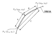
すなわち、図5に示すように、自車両3を中心とするX(車両の左右方向)−Y(車両の前後方向)座標上で、目標進行路のカーブを構成する3つのノードP1(x1,y1)、P2(x2,y2)、P3(x3,y3)を考える。また、P1−P2間の線分をA、P2−P3間の線分をB、P3−P1間の線分をCとすると、3点P1,P2,P3の外接円の半径Rは、以下の(3)式で与えられる。
R=(A+B+C)/(4・Sa) …(3)
That is, as shown in FIG. 5, three nodes P <b> 1 (x <b> 1, x <b> 1, x <b> 1, x <b> 1) constituting the curve of the target traveling path on the X (vehicle left-right direction) -Y (vehicle front-back direction) coordinate. Consider y1), P2 (x2, y2), and P3 (x3, y3). Further, if the line segment between P1 and P2 is A, the line segment between P2 and P3 is B, and the line segment between P3 and P1 is C, the radius R of the circumscribed circle of the three points P1, P2, and P3 is (3).
R = (A + B + C) / (4 · Sa) (3)
ここで、Saは、三角形P1−P2−P3の面積であり、
Sa=(λ・(λ−A)・(λ−B)・(λ−C))1/2 …(4)
但し、λ=(A+B+C)/2
Here, Sa is the area of the triangle P1-P2-P3,
Sa = (λ · (λ−A) · (λ−B) · (λ−C)) 1/2 (4)
However, λ = (A + B + C) / 2
また、各線分A、B、Cは、各座標値より以下の各式により求められる。
A=((y2−y1)2+(x2−x1)2)1/2 …(5)
B=((y3−y2)2+(x3−x2)2)1/2 …(6)
C=((y1−y3)2+(x1−x3)2)1/2 …(7)
次に、S202に進み、予め設定した閾値としての曲率半径閾値Rcを設定する。この曲率半径閾値Rcは、車速Vに応じて可変設定され、例えば、図6に示すマップのように、大きな車速程、大きな値に設定される。尚、この曲率半径閾値Rcは車幅等の条件により可変しても良く、例えば、制御装置3gに記憶された地図情報等により、高速道路や国道等の大きな車幅の走行路では小さな補正項を加算し、他の走行路では大きな補正項を加算して補正する。
Moreover, each line segment A, B, C is calculated | required by each following formula | equation from each coordinate value.
A = ((y2−y1) 2 + (x2−x1) 2 ) 1/2 (5)
B = ((y3-y2) 2 + (x3-x2) 2 ) 1/2 (6)
C = ((y1-y3) 2 + (x1-x3) 2 ) 1/2 (7)
In step S202, a curvature radius threshold value Rc is set as a preset threshold value. The curvature radius threshold value Rc is variably set according to the vehicle speed V, and is set to a large value as the vehicle speed increases, for example, as shown in the map of FIG. The curvature radius threshold Rc may be varied depending on conditions such as the vehicle width. For example, a small correction term is used on a road with a large vehicle width such as an expressway or a national road based on map information stored in the
次いで、S203に進み、目標進行路の曲率半径Rと、曲率半径閾値Rcとを比較し、目標進行路の曲率半径Rが曲率半径閾値Rcより小さい場合(R<Rcの場合)は、S204に進み、前方側自車位置と後方側自車位置とを結んで得られる前方への直線方向を自車進行路として推定し、ルーチンを抜ける。 Next, the process proceeds to S203, where the curvature radius R of the target traveling path is compared with the curvature radius threshold value Rc. If the curvature radius R of the target traveling path is smaller than the curvature radius threshold value Rc (when R <Rc), the process proceeds to S204. Advancing and estimating the forward straight direction obtained by connecting the front side vehicle position and the rear side vehicle position as the own vehicle traveling path, the routine is exited.
逆に、S203での目標進行路の曲率半径Rと曲率半径閾値Rcとの比較の結果、目標進行路の曲率半径Rが曲率半径閾値Rc以上の場合(R≧Rcの場合)は、S205に進み、自車位置(前方側自車位置)の過去の履歴の中から、現在位置より略車長長さ(例えば、5m)手前の自車測位点履歴を抽出し、この5m手前の自車測位点と現在の自車位置とを結んで得られる前方への直線方向を自車進行路として推定し、ルーチンを抜ける。
Conversely, if the curvature radius R of the target traveling path is equal to or larger than the curvature radius threshold Rc as a result of the comparison between the curvature radius R of the target traveling path and the curvature radius threshold value Rc in S203, the process proceeds to S205. Then, from the past history of the vehicle position (front vehicle position), the vehicle positioning point history of approximately the vehicle length (for example, 5 m) before the current position is extracted, and the
すなわち、曲率半径Rが小さい目標進行路では、現在位置より略車長長さ手前の自車測位点と現在の自車位置とを結んで得られる前方への直線方向を自車進行路として推定すると、これら2点において、自車両3の方向が大きく異なり、誘導目標ノードにおける目標ノード偏差ΔDを正確に算出できない虞があるため、前方側自車位置と後方側自車位置とを結んで得られる前方への直線方向を自車進行路として推定するのである。逆に、曲率半径Rが大きい目標進行路では、前方側自車位置と後方側自車位置とを結んで得られる前方への直線方向を自車進行路として推定すると、自車両3の僅かなヨー角が発生した場合でも、微小な偏差量を正確に算出してしまうため、誘導目標ノードにおける目標ノード偏差ΔDから算出した目標ハンドル角δhにこの誤差が反映されてしまい、車両の無用なふらつき(直進収束性の悪化)の原因になると考えられるため、現在位置より略車長長さ手前の自車測位点と現在の自車位置とを結んで得られる前方への直線方向を自車進行路として推定するのである。
In other words, on a target traveling path with a small radius of curvature R, the forward straight direction obtained by connecting the vehicle positioning point approximately the vehicle length before the current position and the current vehicle position is estimated as the vehicle traveling path. Then, at these two points, the direction of the
このように、本実施の形態では、曲率半径Rが小さい目標進行路では、前方側自車位置と後方側自車位置とを結んで得られる前方への直線方向を自車進行路として推定する一方、曲率半径Rが大きい目標進行路では、現在位置より略車長長さ手前の自車測位点と現在の自車位置とを結んで得られる前方への直線方向を自車進行路として推定するので、車両の走行環境に応じて適切に、精度良く自車進行路を設定することができる。そして、この自車進行路を用いて、現在の自車位置と目標進行路とに応じて自車両の走行制御を実行させるので、正確で安定した走行制御が可能となる。 As described above, in the present embodiment, on the target traveling path having a small curvature radius R, the forward straight direction obtained by connecting the front vehicle position and the rear vehicle position is estimated as the vehicle traveling path. On the other hand, on a target traveling path with a large radius of curvature R, the forward straight direction obtained by connecting the own vehicle positioning point approximately the vehicle length before the current position and the current own vehicle position is estimated as the own traveling path. Therefore, the own vehicle traveling path can be set appropriately and accurately according to the traveling environment of the vehicle. Then, using this own vehicle traveling path, the traveling control of the own vehicle is executed according to the current own vehicle position and the target traveling path, so that accurate and stable traveling control is possible.
尚、本実施の形態では、移動局側のGPSアンテナ3a,3dは、自車両3の車室内前後方向に配設するようになっているが、これに限定することなく、車両の横方向に配設するようにしても、車外(例えば前後のバンパ内に組み込み)に配設するようにしても良く、車両における直線位置と、この直線に対する車両の方向が特定できる位置であればどこに設けるようにしても良い。
In the present embodiment, the
1 GPS衛星
2 基準局
2a GPSアンテナ
2b GPS受信機
2c 無線機
3 自車両
3a GPSアンテナ
3b GPS受信機(第1の自車位置検出手段)
3c 無線機
3d GPSアンテナ
3e GPS受信機(第2の自車位置検出手段)
3f 無線機
3g 制御装置(目標進行路設定手段、曲率半径演算手段、自車進行路推定手段、自車両移動情報演算手段)
3h 車速センサ
3l 電動スロットル弁制御装置
3m ブレーキ制御装置
3n 電動パワーステアリング制御装置
代理人 弁理士 伊 藤 進
DESCRIPTION OF SYMBOLS 1 GPS satellite 2
3h Vehicle speed sensor 3l Electric throttle
Agent Patent Attorney Susumu Ito
Claims (5)
上記第1の自車両位置検出手段とは異なる位置に配設され、上記地球を周回する衛星からの情報を基に上記自車両の第1の特定位置とは異なる自車両の第2の特定位置を測位して検出する第2の自車位置検出手段と、
自車両の走行すべき目標進行路を設定する目標進行路設定手段と、
上記目標進行路の曲率半径を演算する曲率半径演算手段と、
上記目標進行路の曲率半径が予め設定した閾値より小さい場合に上記測位された第1の特定位置と上記測位された第2の特定位置とを結んで得られる直線方向を自車両の進行方向として自車進行路を推定する自車進行路推定手段と、
を備えたことを特徴とする車両の進行路推定装置。 A first vehicle position detecting means for detecting and positioning the first specific position of the vehicle based on information from satellites orbiting the earth,
A second specific position of the host vehicle that is disposed at a position different from the first host vehicle position detecting means and is different from the first specific position of the host vehicle based on information from a satellite orbiting the earth. a second vehicle position detecting means for detecting and positioning the,
Target travel path setting means for setting a target travel path for the host vehicle to travel;
A radius of curvature calculating means for calculating a radius of curvature of the target traveling path;
The linear direction obtained by connecting a second specific position of the radius of curvature of the target traveling path is a first specific position and the positioning is the positioning is smaller than a preset threshold and the traveling direction of the vehicle Vehicle traveling path estimation means for estimating the traveling path of the vehicle,
An apparatus for estimating a traveling path of a vehicle.
上記自車進行路推定手段は、上記目標進行路の曲率半径が上記予め設定した閾値を超える場合は、上記自車位置の移動情報を基に自車両の進行方向を求めて自車進行路を推定することを特徴とする請求項1記載の車両の進行路推定装置。 Own vehicle movement information calculating means for obtaining movement information from the time-dependent change of either the first specific position or the second specific position to the current vehicle position;
When the curvature radius of the target travel path exceeds the preset threshold value, the own vehicle travel path estimating means obtains the travel direction of the own vehicle based on the travel information of the own vehicle position and determines the travel path of the own vehicle. The vehicle traveling path estimation apparatus according to claim 1, wherein the traveling path estimation apparatus is estimated.
Priority Applications (3)
| Application Number | Priority Date | Filing Date | Title |
|---|---|---|---|
| JP2003297997A JP4230312B2 (en) | 2003-08-21 | 2003-08-21 | VEHICLE PATH ESTIMATION DEVICE AND TRAVEL CONTROL DEVICE EQUIPPED WITH THE PATH ESTIMATION DEVICE |
| EP04255034A EP1508504B1 (en) | 2003-08-21 | 2004-08-20 | Vehicle-direction estimating device and drive control device including it |
| US10/923,426 US7164985B2 (en) | 2003-08-21 | 2004-08-20 | Vehicle-direction estimating device, and driving control device including the vehicle-direction estimating device |
Applications Claiming Priority (1)
| Application Number | Priority Date | Filing Date | Title |
|---|---|---|---|
| JP2003297997A JP4230312B2 (en) | 2003-08-21 | 2003-08-21 | VEHICLE PATH ESTIMATION DEVICE AND TRAVEL CONTROL DEVICE EQUIPPED WITH THE PATH ESTIMATION DEVICE |
Publications (2)
| Publication Number | Publication Date |
|---|---|
| JP2005070983A JP2005070983A (en) | 2005-03-17 |
| JP4230312B2 true JP4230312B2 (en) | 2009-02-25 |
Family
ID=34056254
Family Applications (1)
| Application Number | Title | Priority Date | Filing Date |
|---|---|---|---|
| JP2003297997A Expired - Fee Related JP4230312B2 (en) | 2003-08-21 | 2003-08-21 | VEHICLE PATH ESTIMATION DEVICE AND TRAVEL CONTROL DEVICE EQUIPPED WITH THE PATH ESTIMATION DEVICE |
Country Status (3)
| Country | Link |
|---|---|
| US (1) | US7164985B2 (en) |
| EP (1) | EP1508504B1 (en) |
| JP (1) | JP4230312B2 (en) |
Cited By (1)
| Publication number | Priority date | Publication date | Assignee | Title |
|---|---|---|---|---|
| US8080257B2 (en) | 2000-12-12 | 2011-12-20 | L'oreal S.A. | Cosmetic compositions containing at least one hetero polymer and at least one film-forming silicone resin and methods of using |
Families Citing this family (22)
| Publication number | Priority date | Publication date | Assignee | Title |
|---|---|---|---|---|
| US9002565B2 (en) | 2003-03-20 | 2015-04-07 | Agjunction Llc | GNSS and optical guidance and machine control |
| US8634993B2 (en) | 2003-03-20 | 2014-01-21 | Agjunction Llc | GNSS based control for dispensing material from vehicle |
| US8214111B2 (en) * | 2005-07-19 | 2012-07-03 | Hemisphere Gps Llc | Adaptive machine control system and method |
| WO2007019864A1 (en) * | 2005-08-18 | 2007-02-22 | Sauer-Danfoss Aps | A method of calibrating and steering a vehicle provided with a positioning system |
| CA2649990A1 (en) * | 2006-06-15 | 2007-12-21 | Uti Limited Partnership | Vehicular navigation and positioning system |
| JP4983132B2 (en) * | 2006-07-26 | 2012-07-25 | 株式会社デンソー | Vehicle direction identification method and vehicle direction identification device. |
| US7855678B2 (en) * | 2007-05-16 | 2010-12-21 | Trimble Navigation Limited | Post-mission high accuracy position and orientation system |
| US20090093959A1 (en) * | 2007-10-04 | 2009-04-09 | Trimble Navigation Limited | Real-time high accuracy position and orientation system |
| FR2938348A3 (en) * | 2008-11-13 | 2010-05-14 | Renault Sas | Global positioning system type positioning sensor's geographic coordinates correcting method for motor vehicle, involves determining angle between speed of sensors and instantaneous speed projection |
| US9173337B2 (en) | 2009-10-19 | 2015-11-03 | Efc Systems, Inc. | GNSS optimized control system and method |
| SE534220C2 (en) | 2009-10-22 | 2011-06-07 | Scania Cv Ab | Automatic friction estimation |
| KR101145112B1 (en) | 2010-05-11 | 2012-05-14 | 국방과학연구소 | Steering control device of autonomous vehicle, autonomous vehicle having the same and steering control method of autonomous vehicle |
| JP5429062B2 (en) | 2010-06-11 | 2014-02-26 | トヨタ自動車株式会社 | Vehicle travel control device |
| JP5429234B2 (en) * | 2011-03-23 | 2014-02-26 | トヨタ自動車株式会社 | Information processing apparatus for vehicle |
| CN105073542B (en) * | 2013-04-01 | 2018-03-16 | 朴秀旼 | Automatic vehicle control system |
| KR101534958B1 (en) * | 2013-12-09 | 2015-07-07 | 현대자동차주식회사 | Apparatus and Method for Controlling of Automatic Steering of Vehicle |
| US9644972B2 (en) * | 2015-03-06 | 2017-05-09 | Tallysman Wireless Inc. | Method for tracking a path taken by a vehicle |
| JP6567936B2 (en) * | 2015-09-30 | 2019-08-28 | 株式会社Subaru | Steering support control device |
| DE102016209778A1 (en) * | 2016-06-03 | 2017-12-07 | Robert Bosch Gmbh | Method and device for carrying out a diagnosis |
| US10831195B2 (en) * | 2016-06-29 | 2020-11-10 | Nidec Corporation | Mobile body guidance system, mobile body, guidance device, and computer program |
| US10191493B2 (en) * | 2016-09-27 | 2019-01-29 | Baidu Usa Llc | Vehicle position point forwarding method for autonomous vehicles |
| DE102019100642A1 (en) | 2018-01-16 | 2019-07-18 | Aisin Seiki Kabushiki Kaisha | Position detection system and processing device |
Family Cites Families (12)
| Publication number | Priority date | Publication date | Assignee | Title |
|---|---|---|---|---|
| FR2656435B1 (en) * | 1989-12-22 | 1996-07-05 | Commissariat Energie Atomique | RECORDING METHOD ON A THEORETICAL TRAJECTORY FOR A VEHICLE BY MODIFYING THE CURVATURE OF THE ACTUAL TRAJECTORY. |
| US5471385A (en) * | 1992-05-21 | 1995-11-28 | Tsubakimoto Chain Co. | Routeless guiding method for moving body |
| US5854987A (en) * | 1995-02-22 | 1998-12-29 | Honda Giken Kogyo Kabushiki Kaisha | Vehicle steering control system using navigation system |
| DE19521358C1 (en) * | 1995-06-12 | 1996-09-05 | Siemens Ag | Slip detection system for 3-wheeled autonomous mobile unit |
| US5729457A (en) * | 1995-07-10 | 1998-03-17 | Motorola, Inc. | Route entry location apparatus |
| US6266582B1 (en) * | 1997-08-06 | 2001-07-24 | Rockwell Collins. Inc. | GPS analytic redundancy for gyroscope failure detection |
| JP4021027B2 (en) * | 1998-01-29 | 2007-12-12 | 富士重工業株式会社 | Travel route recognition device |
| DE19829582C1 (en) * | 1998-07-02 | 2000-03-09 | Daimler Chrysler Ag | Rotation rate measuring method, e.g. for transverse rotation in automobile; compares output signal of rotation rate sensor with differential of angle sensor signal for zero point drift compensation |
| US6681180B2 (en) * | 2001-01-29 | 2004-01-20 | The Board Of Trustees Of The Leland Stanford Junior University | Determination and control of vehicle sideslip using GPS |
| DE10148667C2 (en) * | 2001-06-14 | 2003-06-18 | Bosch Gmbh Robert | Method for determining a vector vehicle speed |
| JP4639545B2 (en) | 2001-07-19 | 2011-02-23 | 日産自動車株式会社 | Vehicle steering control device |
| US6671587B2 (en) * | 2002-02-05 | 2003-12-30 | Ford Motor Company | Vehicle dynamics measuring apparatus and method using multiple GPS antennas |
-
2003
- 2003-08-21 JP JP2003297997A patent/JP4230312B2/en not_active Expired - Fee Related
-
2004
- 2004-08-20 EP EP04255034A patent/EP1508504B1/en not_active Expired - Lifetime
- 2004-08-20 US US10/923,426 patent/US7164985B2/en active Active
Cited By (1)
| Publication number | Priority date | Publication date | Assignee | Title |
|---|---|---|---|---|
| US8080257B2 (en) | 2000-12-12 | 2011-12-20 | L'oreal S.A. | Cosmetic compositions containing at least one hetero polymer and at least one film-forming silicone resin and methods of using |
Also Published As
| Publication number | Publication date |
|---|---|
| EP1508504A3 (en) | 2006-07-05 |
| EP1508504B1 (en) | 2011-05-25 |
| EP1508504A2 (en) | 2005-02-23 |
| US20050043882A1 (en) | 2005-02-24 |
| JP2005070983A (en) | 2005-03-17 |
| US7164985B2 (en) | 2007-01-16 |
Similar Documents
| Publication | Publication Date | Title |
|---|---|---|
| JP4230312B2 (en) | VEHICLE PATH ESTIMATION DEVICE AND TRAVEL CONTROL DEVICE EQUIPPED WITH THE PATH ESTIMATION DEVICE | |
| JP4435519B2 (en) | Vehicle travel control device | |
| JP3570372B2 (en) | Vehicle current position detection device, vehicle current position display device, navigation device, and recording medium | |
| JP3449240B2 (en) | Vehicle current position detection device, vehicle current position display device, navigation device, and recording medium | |
| EP3395139A1 (en) | Automatic steering system | |
| JP6395771B2 (en) | Vehicle position detection device, automatic steering control device, vehicle position detection method, and automatic steering control method | |
| JP2005067483A (en) | Vehicle travel control device | |
| KR20060016180A (en) | Azimuth correction method of moving object in navigation system | |
| US10107631B2 (en) | Methods and systems for vehicle positioning feedback | |
| JP4807728B2 (en) | Vehicle travel control device | |
| JP2017091370A (en) | Travel path information generation system for vehicle and on-vehicle device | |
| US20190120631A1 (en) | Apparatus of compensating for a sensing value of a gyroscope sensor, a system having the same, and a method thereof | |
| JP6836446B2 (en) | Vehicle lane estimation device | |
| JP6248559B2 (en) | Vehicle trajectory calculation device | |
| JP6539129B2 (en) | Vehicle position estimation device, steering control device using the same, and vehicle position estimation method | |
| JP4346993B2 (en) | Vehicle guidance control device | |
| JP2005071114A (en) | Vehicle guidance control device | |
| JP6784629B2 (en) | Vehicle steering support device | |
| CN201016741Y (en) | GPS/INS combined positioning guidance system | |
| KR102244761B1 (en) | Method and apparatus for providing reliability information for positioning information in autonomous vehicle | |
| US7184882B2 (en) | Vehicle navigation system | |
| US11299137B2 (en) | Lateral control for vehicle wireless charging guidance | |
| JP2005070982A (en) | Vehicle travel control device | |
| KR101716232B1 (en) | Vehicle, and control method for the same | |
| KR20090049501A (en) | Vehicle position correction method and device |
Legal Events
| Date | Code | Title | Description |
|---|---|---|---|
| A621 | Written request for application examination |
Free format text: JAPANESE INTERMEDIATE CODE: A621 Effective date: 20060811 |
|
| A131 | Notification of reasons for refusal |
Free format text: JAPANESE INTERMEDIATE CODE: A131 Effective date: 20080826 |
|
| A521 | Request for written amendment filed |
Free format text: JAPANESE INTERMEDIATE CODE: A523 Effective date: 20081024 |
|
| TRDD | Decision of grant or rejection written | ||
| A01 | Written decision to grant a patent or to grant a registration (utility model) |
Free format text: JAPANESE INTERMEDIATE CODE: A01 Effective date: 20081118 |
|
| A01 | Written decision to grant a patent or to grant a registration (utility model) |
Free format text: JAPANESE INTERMEDIATE CODE: A01 |
|
| A61 | First payment of annual fees (during grant procedure) |
Free format text: JAPANESE INTERMEDIATE CODE: A61 Effective date: 20081203 |
|
| R150 | Certificate of patent or registration of utility model |
Ref document number: 4230312 Country of ref document: JP Free format text: JAPANESE INTERMEDIATE CODE: R150 Free format text: JAPANESE INTERMEDIATE CODE: R150 |
|
| FPAY | Renewal fee payment (event date is renewal date of database) |
Free format text: PAYMENT UNTIL: 20111212 Year of fee payment: 3 |
|
| FPAY | Renewal fee payment (event date is renewal date of database) |
Free format text: PAYMENT UNTIL: 20111212 Year of fee payment: 3 |
|
| FPAY | Renewal fee payment (event date is renewal date of database) |
Free format text: PAYMENT UNTIL: 20121212 Year of fee payment: 4 |
|
| R250 | Receipt of annual fees |
Free format text: JAPANESE INTERMEDIATE CODE: R250 |
|
| FPAY | Renewal fee payment (event date is renewal date of database) |
Free format text: PAYMENT UNTIL: 20121212 Year of fee payment: 4 |
|
| FPAY | Renewal fee payment (event date is renewal date of database) |
Free format text: PAYMENT UNTIL: 20131212 Year of fee payment: 5 |
|
| R250 | Receipt of annual fees |
Free format text: JAPANESE INTERMEDIATE CODE: R250 |
|
| R250 | Receipt of annual fees |
Free format text: JAPANESE INTERMEDIATE CODE: R250 |
|
| S531 | Written request for registration of change of domicile |
Free format text: JAPANESE INTERMEDIATE CODE: R313531 |
|
| R350 | Written notification of registration of transfer |
Free format text: JAPANESE INTERMEDIATE CODE: R350 |
|
| R250 | Receipt of annual fees |
Free format text: JAPANESE INTERMEDIATE CODE: R250 |
|
| R250 | Receipt of annual fees |
Free format text: JAPANESE INTERMEDIATE CODE: R250 |
|
| R250 | Receipt of annual fees |
Free format text: JAPANESE INTERMEDIATE CODE: R250 |
|
| S533 | Written request for registration of change of name |
Free format text: JAPANESE INTERMEDIATE CODE: R313533 |
|
| R350 | Written notification of registration of transfer |
Free format text: JAPANESE INTERMEDIATE CODE: R350 |
|
| R250 | Receipt of annual fees |
Free format text: JAPANESE INTERMEDIATE CODE: R250 |
|
| R250 | Receipt of annual fees |
Free format text: JAPANESE INTERMEDIATE CODE: R250 |
|
| R250 | Receipt of annual fees |
Free format text: JAPANESE INTERMEDIATE CODE: R250 |
|
| R250 | Receipt of annual fees |
Free format text: JAPANESE INTERMEDIATE CODE: R250 |
|
| LAPS | Cancellation because of no payment of annual fees |