JP4162833B2 - Extra wire length storage case - Google Patents
Extra wire length storage case Download PDFInfo
- Publication number
- JP4162833B2 JP4162833B2 JP2000144534A JP2000144534A JP4162833B2 JP 4162833 B2 JP4162833 B2 JP 4162833B2 JP 2000144534 A JP2000144534 A JP 2000144534A JP 2000144534 A JP2000144534 A JP 2000144534A JP 4162833 B2 JP4162833 B2 JP 4162833B2
- Authority
- JP
- Japan
- Prior art keywords
- storage
- core wire
- storage tray
- core
- connector
- Prior art date
- Legal status (The legal status is an assumption and is not a legal conclusion. Google has not performed a legal analysis and makes no representation as to the accuracy of the status listed.)
- Expired - Lifetime
Links
Images


Landscapes
- Mechanical Coupling Of Light Guides (AREA)
- Light Guides In General And Applications Therefor (AREA)
Description
【0001】
【発明の属する技術分野】
本発明は、通信ケーブル、特に光ファイバ心線を有する光ファイバケーブルの接続部を保護し、心線余長を収納する収納トレイからなる心線接続余長収納ケースに関するものである。
【0002】
【従来の技術】
従来より、光ファイバケーブルの分岐、引込、接続などを行う場合、ケーブル心線相互を接続すると共に、ケーブル心線の余長分を収納するための心線接続余長収納ケースが用いられている。このケースは、収納トレイに心線を導出入する部分となる心線導出入部と、その心線導出入部から導出入させる幹線用光ファイバケーブルから引き出された光ファイバ心線同士或いは分岐用光ファイバケーブルから引き出された心線とを接続するコネクタ等の接続部が収納されるコネクタ収納部と、さらに接続された心線の余長部分を巻回して保護収納する心線余長収納部とを備えたものが知られている。
特に、このような収納トレイを用いた例として、特許文献〔特開2000−121840号公報〕に示すように複数枚の収納トレイを重ねて多重状態下で支持体に配備するものが本願の特許出願人によって提案されている。
【0003】
【発明が解決しようとする課題】
ところが、光ファイバケーブルを用いた通信網ではケーブルの高密度、多心化が進むにつれて心線余長収納部ではその容量が不足しがちになり、多数枚重ねられた収納トレイの多様化で心線余長の納まりが悪くなって、心線の光損失が生じ伝送特性に悪影響を与えたり接続分岐に伴う作業がやりにくいし、さらには増設も簡単に対応できずコンパクト化できないといった問題が生じている。
【0004】
本発明は、これら従来の事情に鑑みてなされたものであり、光ファイバケーブルの伝送特性に悪影響を与えることなく光ファイバケーブルの接続や切り替え或いは分岐接続作業が容易に実施でき、複数の収納トレイを一括して保持固定でき、配線整理を整然とでき、かつ収納トレイの更新や増設も楽で、きわめてコンパクトに接続部を安定収納することができる取扱い簡便な心線接続余長収納ケースを安価な形態で提供することを目的とするものである。
【0005】
【課題を解決するための手段】
上述の課題を解決するために、請求項1の発明は、光ファイバ心線を導出入する心線導出入部と、該心線導出入部から入る心線相互を接続したコネクタを収納するコネクタ収納部と、心線余長を巻回して収納する心線余長収納部とを有する収納トレイの複数枚をそれぞれピン軸部と軸受部とからなるヒンジ部によって支持体に回動自在で、かつ着脱自在に並設して心線接続余長収納ケースを構成したものであって、前記収納トレイの心線導出入部のある側板両端にピン軸部を対向突設し、また前記支持体に等間隔で複数並設した軸受部に上方に開口されたガイド溝を形成すると共に、該ガイド溝から前記軸受部に前記ピン軸部を挿着して、各収納トレイを順次折り重ねて多重状態下で前記支持体に配備し、さらに前記収納トレイの両側板に係止爪部と係止受部とを設けて、該収納トレイを複数枚積み重ねたときに、隣接する一方の前記収納トレイにある前記係止爪部が、他方の前記収納トレイにある前記係止受部に順次係合するようにして、各収納トレイを段階状にずらせた多重状態下に前記支持体に傾斜保持するように配備し、この複数枚の前記収納トレイを重ね状態で一括して回動して伏せ、その回動最終段階で各収納トレイ同士が、それぞれの前記係止爪部と前記係止受部との係合によって保持固定できる構成としたことを特徴とする。
【0006】
請求項2の発明は、請求項1に記載の心線導出入部のある心線接続余長収納ケースにおいて、複数のコネクタ保持用のコネクタ収納部を有し、各コネクタ収納部に保持されたコネクタから導出される心線余長を収納トレイ内に並設された一対の心線余長収納部に分離して巻回させると共に、前記心線導出入部に心線を挿通保持する弾性保持部材を係脱自在に嵌着配備してなることを特徴とする。
【0007】
請求項3の発明は、請求項1または請求項2に記載の心線接続余長収納ケースにおいて、前記収納トレイの側板の中央に水平状態で仕切壁を設け、該仕切壁の上下両面側にガイドリブによって心線導出入部と、コネクタ収納部と、心線余長収納部とを形成してなることを特徴とする。
【0008】
【作用】
本発明の心線接続余長収納ケースは、光ファイバ心線の接続余長部分を保護収納する複数の収納トレイが互いに回動自在に連結されていて、各収納トレイを重ね状態で一括して回動して伏せ、その回動最終段階で、各収納トレイ同士がそれぞれの係止爪部と係止受部との係合によって保持固定できる構成としてあるので、任意の収納トレイを引き起して開いて心線の接続作業や接続状況の点検、確認、調整などをきわめて容易に行うことができ、心線余長収納終了後に各収納トレイをワンタッチで一括して伏せて保持することができ、その作業性の向上が図れる。
また、各収納トレイは、光ファイバ心線の導出入部のある側板にヒンジ部があって回動するため、収納トレイの回動による光ファイバ心線の長さ変動が少なく納められ、伝送特性に悪影響を及ぼすことがない。
しかも、心線接続後に上側の収納トレイを回動させて元の位置に戻しても光ファイバ心線に弛みが生じないし、心線に過度に屈曲することがなく曲率半径の小さい円弧状部分をも生じないで収納でき安全な保護ができる。
さらに、収納トレイを複数積み重ねたときに、隣接する一方の収納トレイにある係止爪部が、他方の収納トレイにある係止受部に順次係合して段階状にずらせた多重状態下に前記支持体に傾斜保持するようにしてなることにより、配線整理が整然とでき、しかも心線識別がらくであり、かつ連結した収納トレイを別個に外すこともでき、収納トレイの更新並びに増設が容易にできる。
【0009】
【発明の実施の形態】
本発明の実施例を図面を用いて説明すると、心線接続余長収納ケース1は複数枚の同形の収納トレイ10からなり、該収納トレイ10内に光ファイバ心線aを導出入する心線導出入部11と、該心線導出入部11から入る心線相互を接続したコネクタbを収納するコネクタ収納部12と、心線余長を巻回して収納する心線余長収納部13とを備えると共に、この収納トレイ10を複数枚を段階状にづらせて多重に積み重ねた状態下で支持体4に傾斜保持するようにしたものである。
【0010】
そして、前記収納トレイ10は、合成樹脂により一体成形された成形品であり、図1及び図2に示すように、略長方形状の外形を有し、内面側が同一形状に形成されたもので、前記収納トレイ10の心線導出入部11のある側板の両サイドにピン軸部2を対向して突設し、支持体4に設けたピン挿着用の軸受部3,3とを一組としてヒンジ部とし、各収納トレイ10を重ねた状態において、一方の収納トレイ10の係止爪部5を他方の収納トレイ10の係止受部6に嵌挿して両収納トレイ10を互いに傾斜保持してなるものである。
【0011】
前記収納トレイ10としては、図3乃至図6に示すように4心一括収納タイプとしたもので、心線aの接続用コネクタbが収納保持されるコネクタ収納部12と、該コネクタ収納部12に保持された接続用コネクタbから導出される心線余長を引き廻し、ループ状に巻回させて保持する心線余長収納部13とをガイドリブ121,131の仕切壁により区画して備えた略長方形の収納トレイ10を用いる。
この収納トレイ10の外壁側面部の両サイドに設けた一対のピン軸部2と、支持体4に設けた一対の軸受部3とからなるヒンジ部によって隣接される収納トレイ10を互いに支持体4に回動自在、例えば120〜150度回動でき、かつ着脱自在に連結して上下方向に多段に重ねて配備する。
そして、隣接される各収納トレイ10の心線導出入部11のある側板両端にピン軸部2を対向突設し、また前記支持体4に等間隔で複数並設した軸受部3に上方に開口されたガイド溝31を形成すると共に、該ガイド溝3 1 から軸受部3に前記ピン軸部2を挿着して各収納トレイ10を順次折り重ねて多重状態下で前記支持体4に配備し、さらに前記収納トレイ10の両側板に係止爪部5と係止受部6とを設けて、該収納トレイ10を複数枚積み重ねたときに、隣接する一方の前記収納トレイ10にある前記係止爪部5が、他方の前記収納トレイ10にある係止受部6に順次係合するようにし、各収納トレイ10を段階状にずらせた多重状態下に前記支持体4に傾斜保持するように配備し、この複数枚の収納トレイ10を重ね状態で一括して回動して伏せ、その回動最終段階で各収納トレイ同士が、それぞれの前記係止爪部5と前記係止受部6との係合によって保持固定できる構成としてある。
【0012】
また、前記収納トレイ10に形成した舌状の係止片14のある心線導出入部1には、分離スリットのある心線挿通孔を設けた弾性保持部材cを圧入嵌合して心線aの支持を確実にしてあり、この弾性保持部材cは心線径或いは心線数に応じた挿通孔のあるものを選んで用いられる。
さらにコネクタ収納部12及び心線余長収納部13にはガイドリブ121,131及び側壁を選んで心線の浮きを阻止する心線係止片15或いは係止爪16を一体成形して余長の心線aや心線接続部となるコネクタbを収納トレイ10内に確実に保持できるようにしてあって、各収納トレイ10毎に心線aを分離整理収納し、ケーブル挿入部からファイバ心線の曲げが極少で心線収納時のねじれをも防止でき、安全かつ高密度収納で高信頼性が得られる。
【0013】
この場合、多段にずらせて積み重ねられた収納トレイ10の中から所望の収納トレイ10の上段側の収納トレイ10の係止爪部5を係止受部6から外せば、ピン軸部2と軸受部3とからなるヒンジ部を支点として収納トレイ10が回動でき、重ね合せ面を開くことができて下段側の収納トレイ10の内面側が露出されて収納心線の接続配線作業が容易にできる。
【0014】
さらに、一方の収納トレイ10を他方の収納トレイ10に連結するときは、ピン軸2を軸受部3のガイド溝31に挿入して軽く押し込めば、軸受部3がその押力で弾性変位して、軸孔に容易に嵌込まれて回動自在に連結され、収納トレイ10を複数積み重ねたときに隣接する一方の収納トレイ10にある係止受部5が他方の収納トレイ10にある係止受部6に順次係合して段階状にずらせた多重状態下に前記支持体4に傾斜保持することで固定される。
また取り外しの際には、ピン軸部2を軸受部3のガイド溝31から容易にガイド溝31に移し替えられ、ピン軸部2が軸受部3から抜き出し簡単に外すことができ、収納トレイ10内の心線の点検、修理、接続の各作業が簡便に行うことができる。
【0015】
なお、前記心線導出入部11は、片側に設けたシングルタイプに限らず両側に対に設け、即ち四隅に設けたダブルタイプのものを用いることもできるし、しかも合成樹脂の射出成形により、収納トレイ10を略正方形、長方形の四角形または楕円形に形成されるので、コネクタ収納部12に隣接される心線余長収納部13には所定間隔に配列されるケーブル押え用の心線係止片15で伝送特性に悪影響が及ばないように、心線がなめらかに湾曲したループ状に巻回保持できるように配備してある。
【0016】
前記収納トレイ10の複数枚を重ね合わせて心線接続余長収納ケース1として、図6に示すようにベース部材20とカバー部材21とからなる円筒状のクロージャ22内に組み込まれて用いられるが、収納トレイ10を軸支した支持体4が取付部材9を介して設けられる支板8に固定され、前記ベース部材20の挿通孔1にゴム様弾性材例えば、熱可塑性ゴム組成物からなるケーブルシール23を嵌入して、該ケーブルシール23に前記ケーブルAを液密的に貫通させ、該ケーブルAに前記ベース部材20の内面に形成されたケーブル把持金具24に着脱自在に配備する。
この場合、前記カバー部材21の外周面に前記ベース部材20を嵌合してヒンジで開閉自在のバンド25を嵌着してバックルで締付けてベース部材20と、カバー部材21とをパッキン(図示せず)を介して接続連結してある。
【0017】
このクロージャ22の例で説明すると、ベース部材20を介して幹線光ケーブルAが貫通されてケーブル把持金具24で固定され、かつ、該ケーブルのテンションメンバが、テンションメンバ把持金具241に接続連結される。前記カバー部材21は、ベース部材20に収納トレイ10を内装状態下で突き合わせ密封結合して連結一体化するようになっている。
【0018】
なお、収納トレイ10に設けた係合ノブ7は操作把手として使用し、かつ収納トレイ10が複数積み重ねられたときに必要に応じ、ハンド或いは支杆(図示せず)などを嵌挿してベース部材20に連結固定保持するために用いてもよいし、上下段ごとに連結ボスを嵌装して連結する形態とすることもできる。
【0019】
以上の構成からなる収納トレイ10において、ケーブルAから分岐した心線aは収納トレイ10のいずれか一方の第1出入口の心線導出入部11から入ると、ガイドリブ121,131の間の心線通路を通るとともに心線押さえ用の係止片15により押されて、いずれかの心線余長収納部12内に入る。心線aが心線余長収納部13等内に入るときは、前記ガイドリブ131で形成された出入口を通る。そして、心線aは前記係止片15によって押さえられると共に、ガイドリブ131の回りを巻回され、かつコネクタ収納部12の差込ガイドリブ121に取り付けられたコネクタbに接続される。このコネクタbから出る心線aは、その心線余長収納部13を通って、他方の第2出入口の心線導出入部11からケース外部に出る。
なお、前記心線aを押える前記係止片15は、2本上下に分けて、例えば1/2或いは2/3,1/3の位置などに振り分けて突設し、心線aを通する際に上側の係止片15と、下側の係止片15とに分けて通過させるようにし、増設時での配線に各心線aの干渉をなくした安全な配線ができるようにすることが考慮されている。
【0020】
このように、心線導出入部11の一方側から心線aを入れる場合に、心線余長収納部13に収納したときは、他方の心線導出入部11側に出すことができる。
なお、心線導出入部11の一方側から心線aを入れて心線余長収納部13に収納する場合、心線aの巻回の仕方によって、両方の心線導出入部11のいずれの側にも出すこともできる。
以上のように、いずれかの心線導出入部11から心線aを収納トレイ10内に入れることができ、かつ心線aの曲率を小さくすることなく(過負荷を加えることなく)、入口側となった心線導出入部11と同一の又は異なる心線導出入部11を出口側として出すことができる。これにより、心線の出入口側を自在として、光ケーブル用クロージャ内での心線の配線の便宜を図ることができる。
【0021】
ここで、心線導出入部11には、貫通穴が形成されたゴム等の弾性変形可能な弾性保持部材c(図3参照)が設けられ、心線aは、この貫通穴を通って収納トレイ10内に入り、かつ収納トレイ10外に出る。この心線支持用の弾性保持部材cは係止片14により保持される。
このように弾性保持部材cを心線導出入部11に介在させれば、心線aが心線導出入部11を通るときに、心線aがトレイ本体に擦れることが防止でき、引張衝撃等をも確実に防止することができる。
【0022】
そして、収納トレイ10は、光ケーブル用クロージャ内に順次積み重ねられるようにして実装される(図6参照)。この積み重ねには、(トレイ本体上面)側が上側となり、係合用の係止爪部5が下側となるようにする。そして、下側の収納トレイ10の係止受部6に入れれば、重なり合う収納トレイ10同士をネジ止め等することなく連結することができ、心線接続余長収納ケース1とすることができる。例えば、各収納トレイ10を起して開いた状態から一端の収納トレイ10を回動して伏せると、つぎつぎに他の収納トレイ10も将棋倒しに伏せられて、複数の収納トレイ10が一括してそれぞれの係止爪部5と係止受部6によって係止保持固定できる。
【0023】
図7乃至図10の実施例では、心線接続余長収納ケース1として構成する収納トレイ30が、表裏両面を心線aの収納部として使用しうる形態とした例で、トレイ本体の側板31の中央に水平状態で仕切壁32を設け、該仕切壁32の上下両面側にガイドリブによって心線導出入部11と、コネクタ収納部12と、心線余長収納部13とを形成すると共に、ピン軸部2、係止爪部5、係合受部6、ガイドリブ121,131、係止片14,15を一体形成する構成は、前例と同様となっていて各分岐心線aの干渉をなくして、安全に心線余長の収納ができる。
なお、前記心線余長収納部13などは片面に2つ形成してあるが、1つ或いは2つ以上並設したタイプとすることもできる。
そして、複数並設した場合には、隣接される心線余長収納部13に連通路をガイドリブ12 1 ,13 1 で形成して折り返えし巻回でき、心線aの導出入の自由度を高めることも配慮される。
【0024】
【発明の効果】
本発明は、請求項1の発明によれば、収納トレイの心線導出入部のある側板両端にピン軸部を対向突設し、また前記支持体に等間隔で複数並列した軸受部に上方に開口したガイド溝を形成すると共に、該ガイド溝から軸受部に前記ピン軸部を挿着して各収納トレイを順次折り重ねて多重状態下で前記支持体に配備し、この複数枚の収納トレイの両側板に係止爪部と係止受部とを設けて、該収納トレイを複数枚積み重ねたときに、隣接する一方の前記収納トレイにある係止爪部が、他方の前記収納トレイにある係止受部に順次係合するようにし、各収納トレイを段階状にずらせた多重状態下に前記支持体に傾斜保持するように配備し、この複数枚の収納トレイを重ね状態で一括して回動して伏せ、その回動最終段階で各収納トレイ同士が、それぞれの前記係止爪部と前記係止受部との係合によって保持固定できる構成としたことで、上下の収納トレイのヒンジ連結の係脱が簡便にできて、簡単に多段に積み重ねることができ、しかも複数枚重ねられた収納トレイは心線導出入部の側板を中心に互いに回動自在に連結されているので、心線接続作業後に任意の収納トレイを開いて収納されている光ファイバ心線を迅速に取り出すことができ、また複数枚の収納トレイを一括して回動して固定保持できるので、作業簡便で著しく良好であり、心線識別も容易で接続部の再調整や修理など簡単に行うことができ、作業性を大幅に向上すると共に、収納トレイを必要なだけ複数に積み重ねてずらすことができると共に、多段に積み重ねられた収納トレイ全体の確認作業の簡易化と、収納トレイ間を的確に保持できて安全性も高められる。
しかも本発明によれば、心線の分岐、引込の際に収納トレイへの心線導出入の自由度があって作業上、心線接続部へのアクセスが簡便化できると共に、収納トレイの配備がコンパクト化でき、管理や組立分解作業も容易に行なえ、かつ高密度・高信頼性が得られる。 また、請求項2の発明によれば、心線余長の収納が収まり良くでき心線の巻回収納にも余裕があり、しかも心線の保持も緩衝的に行なわれているので、心線に弛みが生じないし、各収納トレイを回動させ展開しても収納した光ファイバの余長部の長さの変化が少ないので、光ファイバの余長部の長さの変化が少なく、光ファイバ心線に無理な屈曲や小円弧が発生することなく光損失をなくして伝送特性を良好な保つことができる。
さらに、請求項3の発明によれば、必要なだけ多段に積み重ねた収納トレイ同士が外れたりずれたりすることなく、心線余長の収納に干渉が生ずることなく安全に取扱うことができ、しかも簡単確実に結合されて識別容易な心線接続余長収納ケースとしてクロージャ内に保持できるので、心線余長収納での高信頼性が得られるし、収納トレイ相互間をネジ止め等することなく脱着でき取扱いも著しく容易化でき、かつコンパクト化が図れる。
【図面の簡単な説明】
【図1】 本発明の一実施例である心線接続余長収納ケースの展開斜視図であって、トレイの一部を開いて内面側を示す図である。
【図2】 図1に示す使用状態を示す側面図である。
【図3】 図2に示す状態の上方から見た平面図である。
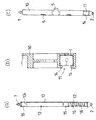
【図4】 図3に示す心線接続余長収納ケースを支持体と分離した状態図であって、(a)は平面図、(b)は収納トレイの底面図である。
【図5】 図4の例の各部分を拡大して示し、(a)はA−A線における拡大縦断面図、(b)はB−B線における部分拡大縦断面図、(c)は収納トレイの全体の側面図である。
【図6】 図1乃至図5の例の心線接続余長収納ケースをクロージャに組み込んだ一使用状態の縦断面図である。
【図7】 本発明の他の実施例を示し、4心分離収納の心線接続余長収納ケースの平面図である。
【図8】 図7の例の底面図である。
【図9】 図7のC−C線における拡大縦断面図である。
【図10】 図7の例の正面図である。
【符号の説明】
A 光ケーブル
a 心線
b コネクタ
c 弾性保持部材
1 心線接続余長収納ケース
2 ピン軸部
3 軸受部
4 支持体
5 係止爪部
6 係止受部
7 係合ノブ
8 支板
9 取付部材
10 収納トレイ
11 心線導出入部
12 コネクタ収納部
121,131 ガイドリブ
13 心線余長収納部
14 係止片
15 係止片
16 係止爪
20 ベース部材
21 カバー部材
23 ケーブルシール
24 ケーブル把持金具
241 テンションメンバ把持金具
25 バンド
30 収納トレイ
31 側板
32 仕切壁[0001]
BACKGROUND OF THE INVENTION
The present invention relates to a cord connection extra length storage case that includes a storage tray that protects a connection portion of a communication cable, particularly an optical fiber cable having an optical fiber cord, and stores the extra length of the core cord.
[0002]
[Prior art]
Conventionally, when branching, drawing in, or connecting an optical fiber cable, a cable connection extra length storage case is used to connect the cable cores to each other and store the extra length of the cable cores. . In this case, a core wire lead-in / out portion which is a portion for leading / leaving a core wire to / from the storage tray, and optical fiber core wires drawn from a core optical fiber cable led out from the core wire lead-in / out portion or a branching optical fiber A connector housing for storing a connector for connecting a core wire drawn from the cable, and a cord extra length housing portion for winding and protecting the extra length of the connected core wire. What you have is known.
In particular, as an example using such a storage tray, as disclosed in Japanese Patent Application Laid-Open No. 2000-121840, a plurality of storage trays are stacked and arranged on a support in a multiplexed state. Proposed by the applicant.
[0003]
[Problems to be solved by the invention]
However, in a communication network using optical fiber cables, the capacity of the extra cable length storage section tends to be insufficient as the cable density increases and the number of cores increases. There is a problem that the extra length of the wire becomes poor, the optical loss of the core wire is adversely affected, the transmission characteristics are adversely affected, the work associated with the connection branching is difficult to perform, and the expansion cannot be easily handled and the size cannot be reduced. ing.
[0004]
The present invention has been made in view of these conventional circumstances, and can easily connect, switch or branch the optical fiber cable without adversely affecting the transmission characteristics of the optical fiber cable. Can be held and fixed in a lump, wiring can be organized, storage trays can be renewed and expanded easily , and the storage area can be stored in a very compact and easy way. It is intended to be provided in the form.
[0005]
[Means for Solving the Problems]
In order to solve the above-mentioned problems, the invention of
[0006]
According to a second aspect of the present invention, there is provided a cord connection surplus length storage case having a core wire lead-in / insertion portion according to
[0007]
According to a third aspect of the present invention, in the cord connection surplus length storage case according to the first or second aspect, a partition wall is provided in a horizontal state at the center of the side plate of the storage tray, and is provided on both upper and lower sides of the partition wall. A core wire lead-in / out part, a connector storage part, and a core wire extra length storage part are formed by guide ribs.
[0008]
[Action]
According to the present invention, there is provided a storage case for connecting the extra length of the optical fiber, wherein a plurality of storage trays that protect and store the extra length of the optical fiber are connected to each other in a rotatable manner. Since the storage trays can be held and fixed by the engagement of the respective locking claws and the locking receiving portions at the final stage of rotation, the storage trays can be lifted up. It is very easy to connect, check, check and adjust the connection status of the cores, and after storing the extra length of the cores, the storage trays can be held together in one touch. The workability can be improved.
In addition, each storage tray is pivoted with a hinge on the side plate where the optical fiber core lead-in / out section is located, so that the length variation of the optical fiber core due to the rotation of the storage tray can be reduced and transmission characteristics can be reduced. There is no adverse effect.
In addition, even if the upper storage tray is rotated to return to the original position after the core wire is connected, the optical fiber core wire does not become slack, and an arc-shaped portion having a small curvature radius without excessive bending to the core wire. It can be stored without causing any damage and safe protection can be achieved.
Furthermore, when a plurality of storage trays are stacked, the locking claw portions on one adjacent storage tray are sequentially engaged with the locking receiving portions on the other storage tray and shifted in stages. By holding the support in an inclined manner, the wiring can be arranged neatly, the core wires can be easily identified, and the connected storage trays can be removed separately, so that the storage trays can be easily renewed and expanded. Can be.
[0009]
DETAILED DESCRIPTION OF THE INVENTION
DESCRIPTION OF THE PREFERRED EMBODIMENTS An embodiment of the present invention will be described with reference to the drawings. A cord connection surplus
[0010]
The
[0011]
As shown in FIGS. 3 to 6, the
The storage trays 10 adjacent to each other by a hinge portion including a pair of
Then, the upper bearing portion 3 a
[0012]
In addition, an elastic holding member c provided with a core wire insertion hole with a separation slit is press-fitted into the core wire lead-in /
[0013]
In this case, by removing the locking
[0014]
Moreover, when connecting the one
Also during removal is being transferred to the
[0015]
The core wire lead-in / out
[0016]
As shown in FIG. 6, a plurality of the
In this case, the
[0017]
Referring to the example of the
[0018]
The
[0019]
The
The locking
[0020]
As described above, when the core wire a is inserted from one side of the core wire lead-in /
In addition, when inserting the core wire a from one side of the core wire lead-in /
As described above, the core wire a can be put into the
[0021]
Here, the core wire lead-in / out
If the elastic holding member c is interposed in the core wire lead-in /
[0022]
The
[0023]
In the embodiment of FIGS. 7 to 10, the
In addition, although the said core wire extra
When it is more
[0024]
【The invention's effect】
According to the first aspect of the present invention, the pin shaft portions are provided so as to be opposed to each other at both ends of the side plate of the storage tray having the lead-in / out portions of the storage tray, and a plurality of bearing portions arranged in parallel at equal intervals above the support body. thereby forming an open guide groove, the guide groove from sequentially folded by inserting the pin shaft portion into the bearing portion of each storage tray is deployed to the support under multistate, the plurality storage tray When the plurality of storage trays are stacked, the locking claw portions on one of the adjacent storage trays are attached to the other storage tray. The storage trays are arranged so as to be engaged with each other in a sequential manner, and the storage trays are tilted and held on the support in a multiplex state where the storage trays are shifted stepwise. And turn it down, and at the final stage of rotation, the storage trays By the above locking claw portion of the record and the holding fixture can be constructed by the engagement between the lock receiving portion, can be stacked to be conveniently have hinged the detachment of the upper and lower storage tray, easily multistage In addition, since the stacked storage trays are connected to each other so as to be rotatable around the side plate of the core wire lead-in / out section, the optical fiber core wires are stored by opening any storage tray after the core wire connection work. Can be quickly removed, and multiple storage trays can be rotated and fixed at once, making it easy to work and remarkably good. The workability can be greatly improved, the storage trays can be stacked as many as necessary, and the storage trays can be shifted and stacked, and the confirmation of the entire storage trays stacked in multiple stages can be simplified. Is also enhanced safety can better retain.
In addition , according to the present invention, there is a degree of freedom of lead-in / out of the core wire to the storage tray when the core wire is branched and retracted, and the access to the core wire connection portion can be simplified in work, and the storage tray can be provided. Can be made compact, and management and assembly / disassembly operations can be easily performed, and high density and high reliability can be obtained. Further, according to the invention of
Furthermore, according to the invention of
[Brief description of the drawings]
FIG. 1 is an exploded perspective view of a cord connection surplus length storage case according to an embodiment of the present invention, showing a part of a tray opened to show an inner surface side.
FIG. 2 is a side view showing a use state shown in FIG.
3 is a plan view seen from above in the state shown in FIG. 2. FIG.
FIGS. 4A and 4B are diagrams illustrating a state where the cord connection extra length storage case shown in FIG. 3 is separated from the support body, wherein FIG. 4A is a plan view and FIG.
5 is an enlarged view of each part of the example of FIG. 4, wherein (a) is an enlarged vertical sectional view taken along line AA, (b) is a partially enlarged longitudinal sectional view taken along line BB, and (c) is shown. It is a side view of the whole storage tray.
6 is a longitudinal cross-sectional view of one use state in which the cord connection excess length storage case of the example of FIGS. 1 to 5 is incorporated in a closure. FIG.
FIG. 7 shows another embodiment of the present invention and is a plan view of a four-fiber separate storage core wire connection extra length storage case.
FIG. 8 is a bottom view of the example of FIG.
9 is an enlarged longitudinal sectional view taken along line CC in FIG.
10 is a front view of the example of FIG.
[Explanation of symbols]
A optical cable a core wire b connector c elastic holding
Claims (3)
Priority Applications (1)
| Application Number | Priority Date | Filing Date | Title |
|---|---|---|---|
| JP2000144534A JP4162833B2 (en) | 2000-05-17 | 2000-05-17 | Extra wire length storage case |
Applications Claiming Priority (1)
| Application Number | Priority Date | Filing Date | Title |
|---|---|---|---|
| JP2000144534A JP4162833B2 (en) | 2000-05-17 | 2000-05-17 | Extra wire length storage case |
Publications (2)
| Publication Number | Publication Date |
|---|---|
| JP2001324621A JP2001324621A (en) | 2001-11-22 |
| JP4162833B2 true JP4162833B2 (en) | 2008-10-08 |
Family
ID=18651179
Family Applications (1)
| Application Number | Title | Priority Date | Filing Date |
|---|---|---|---|
| JP2000144534A Expired - Lifetime JP4162833B2 (en) | 2000-05-17 | 2000-05-17 | Extra wire length storage case |
Country Status (1)
| Country | Link |
|---|---|
| JP (1) | JP4162833B2 (en) |
Families Citing this family (4)
| Publication number | Priority date | Publication date | Assignee | Title |
|---|---|---|---|---|
| JP4495031B2 (en) * | 2005-05-30 | 2010-06-30 | 古河電気工業株式会社 | Optical fiber connection box |
| JP4570583B2 (en) * | 2006-04-27 | 2010-10-27 | 中国電力株式会社 | Optical connection box |
| JP5856449B2 (en) * | 2011-11-25 | 2016-02-09 | 日本電信電話株式会社 | Optical cable connection closure |
| CA3100340A1 (en) * | 2018-05-14 | 2019-11-21 | Afl Telecommunications Llc | Butt closures and organizer assemblies therefor |
-
2000
- 2000-05-17 JP JP2000144534A patent/JP4162833B2/en not_active Expired - Lifetime
Also Published As
| Publication number | Publication date |
|---|---|
| JP2001324621A (en) | 2001-11-22 |
Similar Documents
| Publication | Publication Date | Title |
|---|---|---|
| JP4508404B2 (en) | Cable connection storage cabinet | |
| KR19980703282A (en) | Dome type closure for optical fiber | |
| JP4162833B2 (en) | Extra wire length storage case | |
| JP4786293B2 (en) | Optical cable connection closure | |
| JP3768307B2 (en) | Storage case for optical cable connection | |
| JP3993062B2 (en) | Optical cable connection closure | |
| JP2007121609A (en) | Termination board of closure for optical cable connection | |
| JP4142819B2 (en) | Optical cable connection closure | |
| JP4217352B2 (en) | Optical cable connection closure | |
| JP4960047B2 (en) | Optical cable connection closure | |
| JP2001296432A (en) | Storage case for coated optical fiber connection | |
| JP4231162B2 (en) | Wire connection storage case | |
| JP4231161B2 (en) | Wire connection storage case | |
| JP4044681B2 (en) | Extra wire length storage case | |
| JP3730321B2 (en) | Storage case for optical cable connection | |
| JP3768323B2 (en) | Optical cable connection case | |
| JP3995979B2 (en) | Optical cable connection closure | |
| JP4020200B2 (en) | Optical cable connection storage cabinet | |
| JP3845176B2 (en) | Adapter device in cabinet for storing optical cable connection part | |
| JP3816186B2 (en) | Retention core storage tray in optical cable connection storage cabinet | |
| JP2005091689A (en) | Closure for optical cable connection | |
| JP3816178B2 (en) | Optical cable connection storage cabinet | |
| JP3835886B2 (en) | Optical cable connection storage cabinet | |
| JP3801303B2 (en) | Optical cable connection storage cabinet | |
| JP3947010B2 (en) | Optical cable connection closure |
Legal Events
| Date | Code | Title | Description |
|---|---|---|---|
| A621 | Written request for application examination |
Free format text: JAPANESE INTERMEDIATE CODE: A621 Effective date: 20070406 |
|
| A977 | Report on retrieval |
Free format text: JAPANESE INTERMEDIATE CODE: A971007 Effective date: 20071213 |
|
| A131 | Notification of reasons for refusal |
Free format text: JAPANESE INTERMEDIATE CODE: A131 Effective date: 20080318 |
|
| A521 | Written amendment |
Free format text: JAPANESE INTERMEDIATE CODE: A523 Effective date: 20080514 |
|
| TRDD | Decision of grant or rejection written | ||
| A01 | Written decision to grant a patent or to grant a registration (utility model) |
Free format text: JAPANESE INTERMEDIATE CODE: A01 Effective date: 20080708 |
|
| A01 | Written decision to grant a patent or to grant a registration (utility model) |
Free format text: JAPANESE INTERMEDIATE CODE: A01 |
|
| A61 | First payment of annual fees (during grant procedure) |
Free format text: JAPANESE INTERMEDIATE CODE: A61 Effective date: 20080723 |
|
| FPAY | Renewal fee payment (event date is renewal date of database) |
Free format text: PAYMENT UNTIL: 20110801 Year of fee payment: 3 |
|
| R150 | Certificate of patent or registration of utility model |
Ref document number: 4162833 Country of ref document: JP Free format text: JAPANESE INTERMEDIATE CODE: R150 Free format text: JAPANESE INTERMEDIATE CODE: R150 |
|
| FPAY | Renewal fee payment (event date is renewal date of database) |
Free format text: PAYMENT UNTIL: 20110801 Year of fee payment: 3 |
|
| FPAY | Renewal fee payment (event date is renewal date of database) |
Free format text: PAYMENT UNTIL: 20120801 Year of fee payment: 4 |
|
| FPAY | Renewal fee payment (event date is renewal date of database) |
Free format text: PAYMENT UNTIL: 20120801 Year of fee payment: 4 |
|
| FPAY | Renewal fee payment (event date is renewal date of database) |
Free format text: PAYMENT UNTIL: 20130801 Year of fee payment: 5 |
|
| S531 | Written request for registration of change of domicile |
Free format text: JAPANESE INTERMEDIATE CODE: R313531 |
|
| R350 | Written notification of registration of transfer |
Free format text: JAPANESE INTERMEDIATE CODE: R350 |
|
| EXPY | Cancellation because of completion of term |