JP4120413B2 - Fuel lid structure - Google Patents
Fuel lid structure Download PDFInfo
- Publication number
- JP4120413B2 JP4120413B2 JP2003023051A JP2003023051A JP4120413B2 JP 4120413 B2 JP4120413 B2 JP 4120413B2 JP 2003023051 A JP2003023051 A JP 2003023051A JP 2003023051 A JP2003023051 A JP 2003023051A JP 4120413 B2 JP4120413 B2 JP 4120413B2
- Authority
- JP
- Japan
- Prior art keywords
- lid
- opening
- fuel
- damper
- fuel lid
- Prior art date
- Legal status (The legal status is an assumption and is not a legal conclusion. Google has not performed a legal analysis and makes no representation as to the accuracy of the status listed.)
- Expired - Fee Related
Links
Images


Landscapes
- Cooling, Air Intake And Gas Exhaust, And Fuel Tank Arrangements In Propulsion Units (AREA)
Description
【0001】
【発明の属する技術分野】
本発明は、車体に設けられた給油のためのフューエルリッド開口部をリッド本体により開閉自在としたフューエルリッド構造に関する。
【0002】
【従来の技術】
従来のフューエルリッド構造において、車体の後側部にはフューエルリッド開口部が形成され、内部に給油口が設けられており、リッド本体により開閉自在となっている。このリッド本体は一端部が車体側に支持軸により回転自在に支持されており、他端部がロックピンにより閉止位置に拘束可能であると共に、このロックピンを解除することで外方に開放自在となっている。
【0003】
このような従来のフューエルリッド構造としては、下記に記載した特許文献1がある。
【0004】
【特許文献1】
実公平5−044178号公報
【0005】
【発明が解決しようとする課題】
ところが、上述した特許文献1に記載された「フュエルフィラーリッドのバンパーラバー取付構造」では、車体のフィラー開口部内にヒンジ部材の基端部を枢着し、先端部を外方に延出してフュエルフィラーリッドを連結した、所謂、持ち出しヒンジ機構となっている。そのため、ヒンジ部材の枢着部からフュエルフィラーリッドの取付部までの距離が比較的長くなり、車体振動などが発生するとフュエルフィラーリッドの変位量が大きくなり、このフュエルフィラーリッドがフィラー開口部に接触し、騒音の発生や塗装の剥がれなどを引き起こす要因となっている。
【0006】
なお、このような問題を解消するために、リッドの周縁部にゴムなどのダンパを挟み込み、リッドの閉止時にこのリッドと車体との間にダンパを介在されることで、リッドと車体との接触を防止することが考えられるが、この場合、リッドの開閉方向とダンパの取り付け方向が同じになるため、リッドが開閉するときにダンパがフィラー開口部の周縁に摺接し、リッドからダンパが脱落しやすいという問題がある。
【0007】
本発明はこのような問題を解決するものであって、リッド本体と車体との接触による騒音の発生や塗装の剥がれを防止すると共にダンパの脱落を防止したフューエルリッド構造を提供することを目的とする。
【0008】
【課題を解決するための手段】
上述の目的を達成するための請求項1の発明のフューエルリッド構造では、車体にフューエルリッド開口部を設け、このフューエルリッド開口部を閉止するリッド本体をヒンジ部材をもって略鉛直の軸により開閉自在に支持すると共に、リッド本体の開放時にこのリッド本体全体をフューエルリッド開口部より車体外方へ持ち出すように構成し、リッド本体は、フューエルリッド開口部を閉止する平面部と、この平面部の周縁部に折曲して設けられたフランジ部とを有し、フランジ部に開口部を設け、このフランジ部の開口部に前記リッド本体の閉止状態においてこのリッド本体と前記車体との間に介在するダンパが装着されている。
【0009】
従って、リッド本体によるフューエルリッド開口部の閉止時には、リッド本体と車体との間にダンパが介在しているため、車体振動によりリッド本体と車体とが接触して騒音が発生したり、接触による塗装の剥がれが発生することがなく、また、ダンパがリッド本体の周縁部に設けられているため、リッド本体の開閉動作によるダンパの脱落を防止することができる。
【0010】
また、リッド本体がフューエルリッド開口部を閉止する平面部とこの平面部の周縁部に折曲して設けられたフランジ部とを有し、ダンパがフランジ部に形成された開口部に装着されている。従って、リッド本体の開閉方向とダンパの装着方向が相違するため、リッド本体の開閉時にダンパが車体に摺接してもダンパが外れることはなく、ダンパの脱落を確実に防止することができる。
【0013】
【発明の実施の形態】
以下、本発明の実施の形態を図面に基づいて詳細に説明する。
【0014】
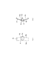
図1に本発明の一実施形態に係るフューエルリッド構造の正面視、図2に図1のII−II断面、図3にリッド本体へのダンパの取付構造を表す概略、図4にリッド本体の概略、図5に本実施形態のフューエルリッド構造が適用された車両の外観を示す。
【0015】
本実施形態のフューエルリッド構造において、図5に示すように、車両11の後部における側面にはフューエルリッド開口部12が形成され、内部に給油口13が設けられ、フューエルリッド開口部12はリッド本体15により開閉自在となっている。この場合、リッド本体15は、例えば、車室内からの遠隔操作により開放可能となっている。
【0016】
図1、図2、図4に示すように、車両11のアウタパネル21には円形状をなすフューエルリッド開口部12が形成され、このフューエルリッド開口部12の内部にお椀形状のインナパネル22が配設され、周縁部がアウタパネル21に固定されている。この場合、インナパネル22の周縁部はリッド開口部12のフランジ部12aに接合されるが、一側部だけはアウタパネル21の裏面に固定されることで、外部に露出しないヒンジ収納部23が形成されている。そして、このインナパネル22に図示しない給油管が取付けられ、給油口13にキャップ14が装着されている。
【0017】
前述したヒンジ収納部23にて、インナパネル22には、上下方向に沿って取付ブラケット24が固定されており、この取付ブラケット24の端部には略鉛直方向に沿った支持軸25が装着されている。そして、上下一対のヒンジ部材26は約180度屈曲したアーム形状をなし、基端部が支持軸25に回転自在に支持され、先端部がフューエルリッド開口部12側に延出している。
【0018】
一方、リッド本体15はフューエルリッド開口部12より若干小径の円盤状をなし、円形の平面部15aと、周縁部が裏側にほぼ90度折曲してリング形状をなすフランジ部15bとを有している。そして、このリッド本体15の裏面には取付ブラケット27が固定されており、ヒンジ収納部23から延出された一対のヒンジ部材26の先端部がこの取付ブラケット27と一体に形成されている。
【0019】
また、一対のヒンジ部材26の基端部には取付ブラケット24を押圧する付勢部材28が取付けられると共に、インナパネル22におけるヒンジ収納部23とは反対側の位置に取付ブラケット27(リッド本体15)を押圧する上下一対の振れ止め機能を有する弾性部材29が取付けられている。更に、弾性部材29に隣接してロックピン30が出没自在に装着される一方、取付ブラケット27にはこのロックピン30が係止する係止孔31が形成されている。
【0020】
従って、リッド本体15を手動によりフューエルリッド開口部12に押し込むことで、ロックピン30が図示しないスプリングにより付勢されて係止孔31に係止し、リッド本体15をフューエルリッド開口部12を閉止する閉止位置に拘束することができる。そして、乗員が車内の操作ハンドルを操作すると、図示しないケーブルを介してロックピン30が牽引され、このロックピン30が係止孔31から外れてリッド本体15の拘束が解除されることで、リッド本体15が付勢部材28弾性部材29の付勢力により閉止位置から外方に押し出され、手動により開放位置に移動することができる。このとき、リッド本体15は全体がフューエルリッド開口部12から外方に持ち出されるように開放することで、このフューエルリッド開口部12を確実に開放することができる。
【0021】
本実施形態にあっては、上述したように、リッド本体15のヒンジ部材26が外方への持ち出し形式において、リッド本体15の周縁部にダンパ41を装着することで、リッド本体15がフューエルリッド開口部12を閉止したとき、このダンパ41がリッド本体15とフューエルリッド開口部12との隙間に介在し、車体振動による両者の接触を防止している。
【0022】
即ち、リッド本体15にて、上下のヒンジ部材26の中間位置をヒンジ取付位置Aと設定すると、このヒンジ取付位置Aから周方向に均等間隔でダンパ41を取付ける2つの開口部42が形成されている。つまり、ヒンジ取付位置Aと2つの開口部42との角度θ1=θ2=θ3=120度に設定されている。そして、各開口部42はリッド本体15のフランジ部15bに円形状をなして形成されている。この場合、狭い幅のフランジ部15bに開口部42を形成するため、このフランジ部15bは開口部42が形成された箇所だけ円弧形状の幅広部15cが形成されている。
【0023】
一方、ダンパ41は、リッド本体15のフランジ部15bの外表面に露出する球面形状をなす本体41aと、開口部42に挿通する軸部41bと、弾性変形して開口部42に挿通可能であると共に抜け止めとなる係止部41cとを有している。
【0024】
従って、ダンパ41は、フランジ部15bに形成された2つの開口部42に対して、その表面側から係止部41cを押し込む、あるいは、係止部41cを押し込んで裏面側から引いて軸部41bを開口部42に挿通することで、リッド本体15の所定の位置に装着することができる。
【0025】
このように本実施形態のフューエルリッド構造にあっては、車体11の後部にフューエルリッド開口部12を設け、このフューエルリッド開口部12を閉止するリッド本体15をヒンジ部材26をもって略鉛直の支持軸25により開閉自在に支持すると共に、リッド本体15の開放時にこのリッド本体全体15をフューエルリッド開口部12より車体外方へ持ち出すように構成し、このリッド本体15の周縁のフランジ部15bに開口部42を設け、この開口部42にリッド本体15の閉止状態にてリッド本体15と車体11との間に介在するダンパ41を設けている。
【0026】
従って、リッド本体15によるフューエルリッド開口部12の閉止時には、リッド本体15と車体11との間にダンパ41が介在しているため、車体11の振動によりリッド本体15と車体11とが接触して騒音が発生したり、接触による塗装の剥がれが発生することがない。また、ダンパ41がリッド本体15のフランジ部15bに装着され、このリッド本体15の開閉方向とダンパ41の装着方向が相違するため、リッド本体15の開閉時にダンパ41が車体に摺接してもダンパ41が外れることはなく、ダンパ41の脱落を確実に防止することができる。
【0027】
また、フューエルリッド開口部12及びリッド本体15が円形状をなしており、ヒンジ部材26の取付位置と2つのダンパ41の取付位置がリッド本体15の周方向に沿ってほぼ均等間隔で設けられている。従って、フューエルリッド開口部12に対して、リッド本体15は周方向均等位置で支持されることとなり、リッド本体15をフューエルリッド開口部12にバランスよく保持し、安定した閉止状態を得ることができる。
【0028】
更に、ダンパ41は、球面形状をなす本体41aがリッド本体15のフランジ部15bの外表面に露出しており、リッド本体15によるフューエルリッド開口部12の閉止時には、ダンパ41は本体41aがフューエルリッド開口部12の周縁に対して点接触することとなり、リッド本体15を安定して保持することができと共に、ダンパ41がリッド本体15の開閉動作に支障を与えることはなく、リッド本体15を円滑に開閉することができる。
【0029】
なお、上述した実施形態において、フューエルリッド開口部12及びリッド本体15が円形状としたが、正方形や長方形であってもよく。また、リッド本体15の周縁にダンパ41を2つ装着したが、ダンパ41の数は1つあるいは3つ以上であってもよい。
【0030】
【発明の効果】
以上、実施形態において詳細に説明したように請求項1の発明のフューエルリッド構造によれば、車体にフューエルリッド開口部を設け、このフューエルリッド開口部を閉止するリッド本体をヒンジ部材をもって略鉛直の軸により開閉自在に支持すると共に、リッド本体の開放時にこのリッド本体全体をフューエルリッド開口部より車体外方へ持ち出すように構成し、リッド本体は、フューエルリッド開口部を閉止する平面部と、この平面部の周縁部に折曲して設けられたフランジ部とを有し、フランジ部に開口部を設け、このフランジ部の開口部に前記リッド本体の閉止状態においてこのリッド本体と前記車体との間に介在するダンパが装着されているので、リッド本体によるフューエルリッド開口部の閉止時には、リッド本体と車体との間にダンパが介在しているため、車体振動によりリッド本体と車体とが接触して騒音が発生したり、接触による塗装の剥がれが発生することがなく、また、ダンパがフランジ部に設けられているため、リッド本体の開閉動作によるダンパの脱落を防止することができる。
【0031】
また、リッド本体をフューエルリッド開口部を閉止する平面部とこの平面部の周縁部に折曲して設けられたフランジ部とで構成し、ダンパをフランジ部に形成された開口部に装着されているので、リッド本体の開閉方向とダンパの装着方向が相違するため、リッド本体の開閉時にダンパが車体に摺接してもダンパが外れることはなく、ダンパの脱落を確実に防止することができる。
【図面の簡単な説明】
【図1】本発明の一実施形態に係るフューエルリッド構造の正面図である。
【図2】図1のII−II断面図である。
【図3】リッド本体へのダンパの取付構造を表す概略図である。
【図4】リッド本体の概略図である。
【図5】本実施形態のフューエルリッド構造が適用された車両の外観図である。
【符号の説明】
11 車体
12 フューエルリッド開口部
15 リッド本体
15a 平面部
15b フランジ部
25 支持軸
26 ヒンジ部材
41 ダンパ
42 開口部[0001]
BACKGROUND OF THE INVENTION
The present invention relates to a fuel lid structure in which a fuel lid opening for refueling provided in a vehicle body can be opened and closed by a lid body.
[0002]
[Prior art]
In the conventional fuel lid structure, a fuel lid opening is formed in the rear side of the vehicle body, and a fuel filler opening is provided inside, so that the lid can be opened and closed freely. One end of the lid body is rotatably supported on the vehicle body side by a support shaft, and the other end can be restrained to a closed position by a lock pin, and can be opened outward by releasing the lock pin. It has become.
[0003]
As such a conventional fuel lid structure, there is
[0004]
[Patent Document 1]
Japanese Utility Model Publication No. 5-04178.
[Problems to be solved by the invention]
However, in the “bumper rubber mounting structure of fuel filler lid” described in
[0006]
In order to solve such problems, a damper such as rubber is sandwiched between the periphery of the lid, and a damper is interposed between the lid and the vehicle body when the lid is closed, so that the contact between the lid and the vehicle body is achieved. In this case, the lid opening / closing direction and the damper mounting direction are the same, so when the lid opens / closes, the damper slides on the periphery of the filler opening, and the damper falls off the lid. There is a problem that it is easy.
[0007]
The present invention solves such problems, and an object of the present invention is to provide a fuel lid structure that prevents generation of noise and peeling of paint due to contact between a lid main body and a vehicle body and prevents a damper from falling off. .
[0008]
[Means for Solving the Problems]
In the fuel lid structure of the invention of
[0009]
Therefore, when the lid of the fuel lid is closed by the lid body, the damper is interposed between the lid body and the vehicle body. The peeling does not occur, and the damper is provided at the peripheral edge of the lid main body, so that it is possible to prevent the damper from falling off due to the opening / closing operation of the lid main body.
[0010]
Further , the lid body has a flat portion for closing the fuel lid opening and a flange portion bent at the peripheral portion of the flat portion, and the damper is attached to the opening formed in the flange portion. . Therefore, since the opening / closing direction of the lid body is different from the mounting direction of the damper, even if the damper slides on the vehicle body when the lid body is opened / closed, the damper does not come off, and the damper can be reliably prevented from falling off.
[0013]
DETAILED DESCRIPTION OF THE INVENTION
Hereinafter, embodiments of the present invention will be described in detail with reference to the drawings.
[0014]
1 is a front view of a fuel lid structure according to an embodiment of the present invention, FIG. 2 is a cross-sectional view taken along the line II-II in FIG. 1, FIG. 3 is a schematic diagram illustrating a structure for attaching a damper to a lid main body, and FIG. FIG. 5 shows the appearance of a vehicle to which the fuel lid structure of the present embodiment is applied.
[0015]
In the fuel lid structure of the present embodiment, as shown in FIG. 5, a
[0016]
As shown in FIGS. 1, 2, and 4, a circular
[0017]
A
[0018]
On the other hand, the
[0019]
A
[0020]
Therefore, when the
[0021]
In the present embodiment, as described above, when the
[0022]
That is, when the intermediate position of the upper and
[0023]
On the other hand, the
[0024]
Therefore, the
[0025]
As described above, in the fuel lid structure of the present embodiment, the fuel lid opening 12 is provided in the rear portion of the vehicle body 11, and the lid
[0026]
Therefore, when the fuel lid opening 12 is closed by the
[0027]
Further, the
[0028]
Further, the
[0029]
In the above-described embodiment, the
[0030]
【The invention's effect】
As described above in detail in the embodiment, according to the fuel lid structure of the invention of
[0031]
Further , the lid main body is composed of a flat portion for closing the fuel lid opening and a flange portion provided by bending the peripheral portion of the flat portion, and the damper is attached to the opening formed in the flange portion . Therefore, since the opening / closing direction of the lid body is different from the mounting direction of the damper, even if the damper slides on the vehicle body when the lid body is opened / closed, the damper does not come off and the damper can be reliably prevented from falling off.
[Brief description of the drawings]
FIG. 1 is a front view of a fuel lid structure according to an embodiment of the present invention.
FIG. 2 is a cross-sectional view taken along the line II-II in FIG.
FIG. 3 is a schematic view showing a structure for attaching a damper to a lid main body.
FIG. 4 is a schematic view of a lid main body.
FIG. 5 is an external view of a vehicle to which the fuel lid structure of the present embodiment is applied.
[Explanation of symbols]
DESCRIPTION OF SYMBOLS 11
Claims (1)
該フューエルリッド開口部を閉止するリッド本体と、
該リッド本体を略鉛直の軸により開閉自在に支持されると共に該リッド本体の開放時に該リッド本体全体を前記フューエルリッド開口部より前記車体外方へ持ち出すヒンジ部材と
を具えたフューエルリッド構造において、
前記リッド本体は、
前記フューエルリッド開口部を閉止する平面部と、該平面部の周縁部に折曲して設けられたフランジ部とを有し、
前記フランジ部に開口部を設け、該フランジ部の開口部に前記リッド本体の閉止状態において該リッド本体と前記車体との間に介在するダンパが装着された
ことを特徴とするフューエルリッド構造。A fuel lid opening provided in the vehicle body;
A lid body for closing the fuel lid opening;
In a fuel lid structure comprising a hinge member that is supported so as to be openable and closable by a substantially vertical shaft and that opens the lid body from the fuel lid opening to the outside of the vehicle body when the lid body is opened.
The lid body is
A flat portion that closes the fuel lid opening, and a flange portion that is bent at the periphery of the flat portion;
An opening provided in the flange portion, and wherein the <br/> that damper interposed is mounted between the vehicle body and the lid body at the closed state of the lid body to the opening of the flange portion the fuel lid Construction.
Priority Applications (1)
| Application Number | Priority Date | Filing Date | Title |
|---|---|---|---|
| JP2003023051A JP4120413B2 (en) | 2003-01-31 | 2003-01-31 | Fuel lid structure |
Applications Claiming Priority (1)
| Application Number | Priority Date | Filing Date | Title |
|---|---|---|---|
| JP2003023051A JP4120413B2 (en) | 2003-01-31 | 2003-01-31 | Fuel lid structure |
Publications (2)
| Publication Number | Publication Date |
|---|---|
| JP2004231084A JP2004231084A (en) | 2004-08-19 |
| JP4120413B2 true JP4120413B2 (en) | 2008-07-16 |
Family
ID=32951965
Family Applications (1)
| Application Number | Title | Priority Date | Filing Date |
|---|---|---|---|
| JP2003023051A Expired - Fee Related JP4120413B2 (en) | 2003-01-31 | 2003-01-31 | Fuel lid structure |
Country Status (1)
| Country | Link |
|---|---|
| JP (1) | JP4120413B2 (en) |
Families Citing this family (4)
| Publication number | Priority date | Publication date | Assignee | Title |
|---|---|---|---|---|
| TWI494231B (en) * | 2012-02-02 | 2015-08-01 | Sanyang Industry Co Ltd | Fuel cap shock absorption mechanism |
| JP2016196334A (en) * | 2016-08-16 | 2016-11-24 | 株式会社バンダイ | Container for goods |
| JP6323626B1 (en) * | 2016-09-12 | 2018-05-16 | Jfeスチール株式会社 | Clad welded tube and manufacturing method thereof |
| JP6911736B2 (en) * | 2017-12-04 | 2021-07-28 | トヨタ自動車株式会社 | Vehicle refueling section structure |
-
2003
- 2003-01-31 JP JP2003023051A patent/JP4120413B2/en not_active Expired - Fee Related
Also Published As
| Publication number | Publication date |
|---|---|
| JP2004231084A (en) | 2004-08-19 |
Similar Documents
| Publication | Publication Date | Title |
|---|---|---|
| US4527825A (en) | Fuel filler door with dual hinge | |
| JP5663715B2 (en) | Vehicle safety handle | |
| JP3935020B2 (en) | Lid opening / closing mechanism and vehicle storage device | |
| JP5585362B2 (en) | Charging port cover arrangement structure | |
| JP5437374B2 (en) | Glove box for vehicle | |
| JP5109465B2 (en) | Tether anchor unit | |
| JP4120413B2 (en) | Fuel lid structure | |
| JP5545158B2 (en) | Charging port cover arrangement structure | |
| JP4751768B2 (en) | Vehicle door handle structure | |
| JP5706075B2 (en) | Latch device and seat device | |
| JP3600038B2 (en) | Opener device | |
| JP5786683B2 (en) | Charging lid structure for vehicles | |
| JP2019143374A (en) | Vehicle door latch device | |
| JP2929868B2 (en) | Vehicle fuel filler structure | |
| JP2005343367A (en) | Fuel lid mounting structure | |
| JP2917121B2 (en) | Console Box | |
| JP3752856B2 (en) | Console box door opening and closing mechanism | |
| JP4159842B2 (en) | Console box structure | |
| JPH1134747A (en) | Lock structure for glove compartment | |
| JPH0535911Y2 (en) | ||
| JPH0346252Y2 (en) | ||
| JP3697068B2 (en) | Lid arm structure | |
| JP2002067813A (en) | Vehicular storage container | |
| JP3760602B2 (en) | Automotive filler cap equipment | |
| JPS6126108Y2 (en) |
Legal Events
| Date | Code | Title | Description |
|---|---|---|---|
| A621 | Written request for application examination |
Free format text: JAPANESE INTERMEDIATE CODE: A621 Effective date: 20050407 |
|
| A977 | Report on retrieval |
Free format text: JAPANESE INTERMEDIATE CODE: A971007 Effective date: 20071128 |
|
| A131 | Notification of reasons for refusal |
Free format text: JAPANESE INTERMEDIATE CODE: A131 Effective date: 20071204 |
|
| A521 | Written amendment |
Free format text: JAPANESE INTERMEDIATE CODE: A523 Effective date: 20080131 |
|
| TRDD | Decision of grant or rejection written | ||
| A01 | Written decision to grant a patent or to grant a registration (utility model) |
Free format text: JAPANESE INTERMEDIATE CODE: A01 Effective date: 20080401 |
|
| A61 | First payment of annual fees (during grant procedure) |
Free format text: JAPANESE INTERMEDIATE CODE: A61 Effective date: 20080414 |
|
| FPAY | Renewal fee payment (event date is renewal date of database) |
Free format text: PAYMENT UNTIL: 20110509 Year of fee payment: 3 |
|
| R150 | Certificate of patent or registration of utility model |
Ref document number: 4120413 Country of ref document: JP Free format text: JAPANESE INTERMEDIATE CODE: R150 Free format text: JAPANESE INTERMEDIATE CODE: R150 |
|
| FPAY | Renewal fee payment (event date is renewal date of database) |
Free format text: PAYMENT UNTIL: 20110509 Year of fee payment: 3 |
|
| FPAY | Renewal fee payment (event date is renewal date of database) |
Free format text: PAYMENT UNTIL: 20120509 Year of fee payment: 4 |
|
| FPAY | Renewal fee payment (event date is renewal date of database) |
Free format text: PAYMENT UNTIL: 20130509 Year of fee payment: 5 |
|
| FPAY | Renewal fee payment (event date is renewal date of database) |
Free format text: PAYMENT UNTIL: 20140509 Year of fee payment: 6 |
|
| S531 | Written request for registration of change of domicile |
Free format text: JAPANESE INTERMEDIATE CODE: R313531 |
|
| R350 | Written notification of registration of transfer |
Free format text: JAPANESE INTERMEDIATE CODE: R350 |
|
| LAPS | Cancellation because of no payment of annual fees |