JP4093964B2 - Resistance furnace - Google Patents
Resistance furnace Download PDFInfo
- Publication number
- JP4093964B2 JP4093964B2 JP2003562552A JP2003562552A JP4093964B2 JP 4093964 B2 JP4093964 B2 JP 4093964B2 JP 2003562552 A JP2003562552 A JP 2003562552A JP 2003562552 A JP2003562552 A JP 2003562552A JP 4093964 B2 JP4093964 B2 JP 4093964B2
- Authority
- JP
- Japan
- Prior art keywords
- resistance furnace
- heating element
- annular
- heating
- annular collar
- Prior art date
- Legal status (The legal status is an assumption and is not a legal conclusion. Google has not performed a legal analysis and makes no representation as to the accuracy of the status listed.)
- Expired - Fee Related
Links
- 238000010438 heat treatment Methods 0.000 claims abstract description 116
- 238000001816 cooling Methods 0.000 claims description 33
- 239000012494 Quartz wool Substances 0.000 claims description 9
- 239000000110 cooling liquid Substances 0.000 claims description 6
- 229910052751 metal Inorganic materials 0.000 claims description 5
- 239000002184 metal Substances 0.000 claims description 5
- 230000001681 protective effect Effects 0.000 claims description 5
- RYGMFSIKBFXOCR-UHFFFAOYSA-N Copper Chemical compound [Cu] RYGMFSIKBFXOCR-UHFFFAOYSA-N 0.000 claims description 4
- 239000002826 coolant Substances 0.000 claims description 4
- 229910052802 copper Inorganic materials 0.000 claims description 4
- 239000010949 copper Substances 0.000 claims description 4
- 229910000881 Cu alloy Inorganic materials 0.000 claims description 3
- 238000011010 flushing procedure Methods 0.000 claims description 3
- 229910004298 SiO 2 Inorganic materials 0.000 claims 1
- 239000007789 gas Substances 0.000 description 44
- 238000009826 distribution Methods 0.000 description 25
- 238000000265 homogenisation Methods 0.000 description 10
- OKTJSMMVPCPJKN-UHFFFAOYSA-N Carbon Chemical compound [C] OKTJSMMVPCPJKN-UHFFFAOYSA-N 0.000 description 9
- 239000000463 material Substances 0.000 description 8
- IJGRMHOSHXDMSA-UHFFFAOYSA-N Atomic nitrogen Chemical compound N#N IJGRMHOSHXDMSA-UHFFFAOYSA-N 0.000 description 6
- VYPSYNLAJGMNEJ-UHFFFAOYSA-N Silicium dioxide Chemical compound O=[Si]=O VYPSYNLAJGMNEJ-UHFFFAOYSA-N 0.000 description 6
- 229910002804 graphite Inorganic materials 0.000 description 6
- 239000010439 graphite Substances 0.000 description 6
- 239000000498 cooling water Substances 0.000 description 4
- 238000004519 manufacturing process Methods 0.000 description 3
- 229910052757 nitrogen Inorganic materials 0.000 description 3
- 239000002470 thermal conductor Substances 0.000 description 3
- 229910052799 carbon Inorganic materials 0.000 description 2
- 239000004020 conductor Substances 0.000 description 2
- 230000003647 oxidation Effects 0.000 description 2
- 238000007254 oxidation reaction Methods 0.000 description 2
- BASFCYQUMIYNBI-UHFFFAOYSA-N platinum Chemical compound [Pt] BASFCYQUMIYNBI-UHFFFAOYSA-N 0.000 description 2
- 125000006850 spacer group Chemical group 0.000 description 2
- XLYOFNOQVPJJNP-UHFFFAOYSA-N water Substances O XLYOFNOQVPJJNP-UHFFFAOYSA-N 0.000 description 2
- ZOKXTWBITQBERF-UHFFFAOYSA-N Molybdenum Chemical compound [Mo] ZOKXTWBITQBERF-UHFFFAOYSA-N 0.000 description 1
- QVGXLLKOCUKJST-UHFFFAOYSA-N atomic oxygen Chemical compound [O] QVGXLLKOCUKJST-UHFFFAOYSA-N 0.000 description 1
- 230000015572 biosynthetic process Effects 0.000 description 1
- 238000009529 body temperature measurement Methods 0.000 description 1
- 230000015556 catabolic process Effects 0.000 description 1
- 239000000919 ceramic Substances 0.000 description 1
- 238000003486 chemical etching Methods 0.000 description 1
- 238000005660 chlorination reaction Methods 0.000 description 1
- 239000003245 coal Substances 0.000 description 1
- 229910052681 coesite Inorganic materials 0.000 description 1
- 229910052906 cristobalite Inorganic materials 0.000 description 1
- 238000006731 degradation reaction Methods 0.000 description 1
- 238000013461 design Methods 0.000 description 1
- 238000011161 development Methods 0.000 description 1
- 230000005611 electricity Effects 0.000 description 1
- 230000002349 favourable effect Effects 0.000 description 1
- 229910021397 glassy carbon Inorganic materials 0.000 description 1
- 230000006698 induction Effects 0.000 description 1
- 230000001788 irregular Effects 0.000 description 1
- 238000012423 maintenance Methods 0.000 description 1
- 150000002739 metals Chemical class 0.000 description 1
- 238000000034 method Methods 0.000 description 1
- 238000012986 modification Methods 0.000 description 1
- 230000004048 modification Effects 0.000 description 1
- 229910052750 molybdenum Inorganic materials 0.000 description 1
- 239000011733 molybdenum Substances 0.000 description 1
- 239000013307 optical fiber Substances 0.000 description 1
- 239000001301 oxygen Substances 0.000 description 1
- 229910052760 oxygen Inorganic materials 0.000 description 1
- 229910052697 platinum Inorganic materials 0.000 description 1
- 238000003825 pressing Methods 0.000 description 1
- 239000004065 semiconductor Substances 0.000 description 1
- 239000000377 silicon dioxide Substances 0.000 description 1
- 235000012239 silicon dioxide Nutrition 0.000 description 1
- 229910052682 stishovite Inorganic materials 0.000 description 1
- 229910052715 tantalum Inorganic materials 0.000 description 1
- GUVRBAGPIYLISA-UHFFFAOYSA-N tantalum atom Chemical compound [Ta] GUVRBAGPIYLISA-UHFFFAOYSA-N 0.000 description 1
- 229910052905 tridymite Inorganic materials 0.000 description 1
- 238000009827 uniform distribution Methods 0.000 description 1
Images


Classifications
-
- F—MECHANICAL ENGINEERING; LIGHTING; HEATING; WEAPONS; BLASTING
- F27—FURNACES; KILNS; OVENS; RETORTS
- F27D—DETAILS OR ACCESSORIES OF FURNACES, KILNS, OVENS OR RETORTS, IN SO FAR AS THEY ARE OF KINDS OCCURRING IN MORE THAN ONE KIND OF FURNACE
- F27D11/00—Arrangement of elements for electric heating in or on furnaces
- F27D11/02—Ohmic resistance heating
-
- H—ELECTRICITY
- H01—ELECTRIC ELEMENTS
- H01L—SEMICONDUCTOR DEVICES NOT COVERED BY CLASS H10
- H01L21/00—Processes or apparatus adapted for the manufacture or treatment of semiconductor or solid state devices or of parts thereof
- H01L21/67—Apparatus specially adapted for handling semiconductor or electric solid state devices during manufacture or treatment thereof; Apparatus specially adapted for handling wafers during manufacture or treatment of semiconductor or electric solid state devices or components ; Apparatus not specifically provided for elsewhere
- H01L21/67005—Apparatus not specifically provided for elsewhere
- H01L21/67011—Apparatus for manufacture or treatment
- H01L21/67098—Apparatus for thermal treatment
- H01L21/67109—Apparatus for thermal treatment mainly by convection
-
- C—CHEMISTRY; METALLURGY
- C03—GLASS; MINERAL OR SLAG WOOL
- C03B—MANUFACTURE, SHAPING, OR SUPPLEMENTARY PROCESSES
- C03B23/00—Re-forming shaped glass
- C03B23/04—Re-forming tubes or rods
- C03B23/043—Heating devices specially adapted for re-forming tubes or rods in general, e.g. burners
-
- C—CHEMISTRY; METALLURGY
- C03—GLASS; MINERAL OR SLAG WOOL
- C03B—MANUFACTURE, SHAPING, OR SUPPLEMENTARY PROCESSES
- C03B37/00—Manufacture or treatment of flakes, fibres, or filaments from softened glass, minerals, or slags
- C03B37/01—Manufacture of glass fibres or filaments
- C03B37/012—Manufacture of preforms for drawing fibres or filaments
- C03B37/01205—Manufacture of preforms for drawing fibres or filaments starting from tubes, rods, fibres or filaments
- C03B37/01225—Means for changing or stabilising the shape, e.g. diameter, of tubes or rods in general, e.g. collapsing
- C03B37/01257—Heating devices therefor
-
- F—MECHANICAL ENGINEERING; LIGHTING; HEATING; WEAPONS; BLASTING
- F27—FURNACES; KILNS; OVENS; RETORTS
- F27B—FURNACES, KILNS, OVENS OR RETORTS IN GENERAL; OPEN SINTERING OR LIKE APPARATUS
- F27B17/00—Furnaces of a kind not covered by any of groups F27B1/00 - F27B15/00
-
- F—MECHANICAL ENGINEERING; LIGHTING; HEATING; WEAPONS; BLASTING
- F27—FURNACES; KILNS; OVENS; RETORTS
- F27D—DETAILS OR ACCESSORIES OF FURNACES, KILNS, OVENS OR RETORTS, IN SO FAR AS THEY ARE OF KINDS OCCURRING IN MORE THAN ONE KIND OF FURNACE
- F27D21/00—Arrangement of monitoring devices; Arrangement of safety devices
- F27D21/0014—Devices for monitoring temperature
-
- H—ELECTRICITY
- H05—ELECTRIC TECHNIQUES NOT OTHERWISE PROVIDED FOR
- H05B—ELECTRIC HEATING; ELECTRIC LIGHT SOURCES NOT OTHERWISE PROVIDED FOR; CIRCUIT ARRANGEMENTS FOR ELECTRIC LIGHT SOURCES, IN GENERAL
- H05B3/00—Ohmic-resistance heating
- H05B3/62—Heating elements specially adapted for furnaces
-
- F—MECHANICAL ENGINEERING; LIGHTING; HEATING; WEAPONS; BLASTING
- F27—FURNACES; KILNS; OVENS; RETORTS
- F27B—FURNACES, KILNS, OVENS OR RETORTS IN GENERAL; OPEN SINTERING OR LIKE APPARATUS
- F27B9/00—Furnaces through which the charge is moved mechanically, e.g. of tunnel type; Similar furnaces in which the charge moves by gravity
- F27B9/28—Furnaces through which the charge is moved mechanically, e.g. of tunnel type; Similar furnaces in which the charge moves by gravity for treating continuous lengths of work
-
- F—MECHANICAL ENGINEERING; LIGHTING; HEATING; WEAPONS; BLASTING
- F27—FURNACES; KILNS; OVENS; RETORTS
- F27D—DETAILS OR ACCESSORIES OF FURNACES, KILNS, OVENS OR RETORTS, IN SO FAR AS THEY ARE OF KINDS OCCURRING IN MORE THAN ONE KIND OF FURNACE
- F27D9/00—Cooling of furnaces or of charges therein
- F27D2009/0002—Cooling of furnaces
- F27D2009/0045—Cooling of furnaces the cooling medium passing a block, e.g. metallic
-
- F—MECHANICAL ENGINEERING; LIGHTING; HEATING; WEAPONS; BLASTING
- F27—FURNACES; KILNS; OVENS; RETORTS
- F27D—DETAILS OR ACCESSORIES OF FURNACES, KILNS, OVENS OR RETORTS, IN SO FAR AS THEY ARE OF KINDS OCCURRING IN MORE THAN ONE KIND OF FURNACE
- F27D19/00—Arrangements of controlling devices
- F27D2019/0006—Monitoring the characteristics (composition, quantities, temperature, pressure) of at least one of the gases of the kiln atmosphere and using it as a controlling value
- F27D2019/0025—Monitoring the temperature of a part or of an element of the furnace structure
-
- F—MECHANICAL ENGINEERING; LIGHTING; HEATING; WEAPONS; BLASTING
- F27—FURNACES; KILNS; OVENS; RETORTS
- F27D—DETAILS OR ACCESSORIES OF FURNACES, KILNS, OVENS OR RETORTS, IN SO FAR AS THEY ARE OF KINDS OCCURRING IN MORE THAN ONE KIND OF FURNACE
- F27D99/00—Subject matter not provided for in other groups of this subclass
- F27D99/0001—Heating elements or systems
- F27D99/0006—Electric heating elements or system
- F27D2099/0008—Resistor heating
- F27D2099/001—Resistor heating the container being the resistor
-
- F—MECHANICAL ENGINEERING; LIGHTING; HEATING; WEAPONS; BLASTING
- F27—FURNACES; KILNS; OVENS; RETORTS
- F27D—DETAILS OR ACCESSORIES OF FURNACES, KILNS, OVENS OR RETORTS, IN SO FAR AS THEY ARE OF KINDS OCCURRING IN MORE THAN ONE KIND OF FURNACE
- F27D7/00—Forming, maintaining or circulating atmospheres in heating chambers
- F27D7/02—Supplying steam, vapour, gases or liquids
-
- F—MECHANICAL ENGINEERING; LIGHTING; HEATING; WEAPONS; BLASTING
- F27—FURNACES; KILNS; OVENS; RETORTS
- F27D—DETAILS OR ACCESSORIES OF FURNACES, KILNS, OVENS OR RETORTS, IN SO FAR AS THEY ARE OF KINDS OCCURRING IN MORE THAN ONE KIND OF FURNACE
- F27D7/00—Forming, maintaining or circulating atmospheres in heating chambers
- F27D7/06—Forming or maintaining special atmospheres or vacuum within heating chambers
-
- F—MECHANICAL ENGINEERING; LIGHTING; HEATING; WEAPONS; BLASTING
- F27—FURNACES; KILNS; OVENS; RETORTS
- F27D—DETAILS OR ACCESSORIES OF FURNACES, KILNS, OVENS OR RETORTS, IN SO FAR AS THEY ARE OF KINDS OCCURRING IN MORE THAN ONE KIND OF FURNACE
- F27D99/00—Subject matter not provided for in other groups of this subclass
- F27D99/0073—Seals
Landscapes
- Engineering & Computer Science (AREA)
- Chemical & Material Sciences (AREA)
- Mechanical Engineering (AREA)
- General Engineering & Computer Science (AREA)
- Organic Chemistry (AREA)
- Materials Engineering (AREA)
- Manufacturing & Machinery (AREA)
- General Physics & Mathematics (AREA)
- Microelectronics & Electronic Packaging (AREA)
- Power Engineering (AREA)
- Computer Hardware Design (AREA)
- Condensed Matter Physics & Semiconductors (AREA)
- Physics & Mathematics (AREA)
- Life Sciences & Earth Sciences (AREA)
- General Life Sciences & Earth Sciences (AREA)
- Geochemistry & Mineralogy (AREA)
- Resistance Heating (AREA)
- Furnace Details (AREA)
- Electronic Switches (AREA)
- Non-Adjustable Resistors (AREA)
Abstract
Description
本発明は、垂直に配向された長手方向軸を有する管状加熱要素を具備する抵抗炉に関し、この要素は、上部側と下部側とによって画成され、かつ、炉チャンバを囲繞するシェル表面を具備し、また該要素は供給端子に接続され、それによって加熱電流は、電力供給点で加熱要素内に導入される。 The present invention relates to a resistance furnace comprising a tubular heating element having a longitudinally oriented longitudinal axis, the element being defined by an upper side and a lower side and comprising a shell surface surrounding the furnace chamber. And the element is connected to the supply terminal, whereby a heating current is introduced into the heating element at the power supply point.
抵抗炉の助けで高温を達成することができる。電流は、熱伝導体として設計されたオーム抵抗器を通って流れ、電力は主に熱に転換される。モリブデン、タンタルおよびプラチナ等の金属、セラミック、SiC、または、石炭、グラファイトまたはガラス質カーボン(熱生成カーボン)等の炭素の改質物は、熱伝導体用の材料として適している。グラファイト製の熱伝導体は、その高温抵抗、簡略な形状および低価格によって特徴づけられる。 High temperatures can be achieved with the help of a resistance furnace. Current flows through an ohmic resistor designed as a heat conductor, and power is primarily converted to heat. Metals such as molybdenum, tantalum and platinum, ceramics, SiC, or carbon modifications such as coal, graphite or vitreous carbon (thermally generated carbon) are suitable as materials for thermal conductors. Graphite thermal conductors are characterized by their high temperature resistance, simple shape and low cost.
抵抗炉は、例えば、半導体材料を溶融するために、または、ロッド状または管状の開始シリンダを加熱してそれからチューブ、ロッドまたは光ファイバを伸張するために使用される。意図的に非均質な加熱容量が望ましい(例えば、多角形断面を有するシリンダを引いている間等)特別な場合を除いて、通常は、加熱材料の均一な加熱に重きがおかれる。 Resistance furnaces are used, for example, to melt semiconductor material or to heat a rod-like or tubular starting cylinder and then stretch a tube, rod or optical fiber. Except in special cases where intentionally non-homogeneous heating capacities are desired (eg, while pulling a cylinder with a polygonal cross section), usually the emphasis is on uniform heating of the heating material.
局所加熱容量は、電流密度に正比例し、後者は、電流の流れと、熱伝導体の材料の断面積および抵抗率と、によって規定される。抵抗率は、今度は、局所温度に依存する。熱伝導体材料の比較的低い伝導性および付随する電圧低下によって、均質な温度プロファイルを生成し維持することが困難になる。 The local heating capacity is directly proportional to the current density, the latter being defined by the current flow and the cross-sectional area and resistivity of the heat conductor material. The resistivity now depends on the local temperature. The relatively low conductivity of the thermal conductor material and the accompanying voltage drop makes it difficult to generate and maintain a homogeneous temperature profile.
したがって米国特許第4,703,556号には、グラファイト製の加熱チューブを有する炉が提案されており、複数の軸方向に延在する長手方向スロットが加熱チューブの円周にわたって分布され、加熱チューブのほぼ全高さにわたって上部からおよび下部から交互のやり方で延在する。したがって、電気は、曲がりくねったように加熱チューブの残りのウェブを通って流れる。これは、結果として、垂直方向における温度曲線の均質化になる。 Thus, US Pat. No. 4,703,556 proposes a furnace having a graphite heating tube, in which a plurality of axially extending longitudinal slots are distributed around the circumference of the heating tube. Extends in an alternating manner from the top and from the bottom over almost the entire height. Thus, electricity flows through the remaining web of the heated tube in a twisted manner. This results in a homogenization of the temperature curve in the vertical direction.
加熱チューブ内の電流密度のさらなる均質化は、加熱電流の供給のために2つのグラファイト接続片が設けられるという措置によって達成され、上記片は、加熱チューブの底側の区域に向き合った場所へねじ込まれ、別個のトランスによって供給される。電圧低下は、加熱チューブウェブの長さ全体にわたって第2の電力供給点によって妨げることができ、結果として、電流および温度分布の改良された垂直および水平の均質化になる。 Further homogenization of the current density in the heating tube is achieved by the measure that two graphite connection pieces are provided for supplying the heating current, which is screwed into a location facing the bottom area of the heating tube. And is supplied by a separate transformer. The voltage drop can be prevented by a second power supply point throughout the length of the heated tube web, resulting in improved vertical and horizontal homogenization of the current and temperature distribution.
しかし、知られている加熱チューブを製造することは非常に複雑である。その線条細工形状のため、機械的損傷を受けやすく、したがって、頻繁に交換しなければならない。さらに、供給端子の領域の拡大縮小および酸化のため、電気接触の劣化および不確定な電力供給の可能性があり、したがって、加熱チューブに対する不規則な加熱操作および温度分布の可能性がある。このリスクは、供給端子が最大温度負荷のゾーンのすぐ隣に位置するという事実によっていっそう高まる。 However, manufacturing known heating tubes is very complex. Due to its striated shape, it is prone to mechanical damage and must therefore be replaced frequently. Furthermore, due to the scaling and oxidation of the area of the supply terminals, there is the possibility of electrical contact degradation and indeterminate power supply, and thus the possibility of irregular heating operations and temperature distribution on the heating tube. This risk is further increased by the fact that the supply terminal is located immediately next to the zone of maximum temperature load.
高性能抵抗炉(約100kW以上)において、温度シンクは特に注意され、均質な温度分布を調整し維持することがますます困難になる。 In high performance resistance furnaces (above about 100 kW), temperature sinks are particularly noted and it becomes increasingly difficult to adjust and maintain a homogeneous temperature distribution.
本発明の目的は、電気抵抗炉を提供することであり、特に、製造および維持にあまり労力がかからずかつ作用信頼性が高いことによって特徴づけられ、炉内で軸方向および半径方向に均質な温度プロファイルを再現可能に調整することを可能にする高性能電気抵抗炉を提供することである。 The object of the present invention is to provide an electric resistance furnace, which is characterized in particular by less labor and manufacture and maintenance and high operational reliability and is homogeneous in the axial and radial directions within the furnace. It is an object to provide a high performance electric resistance furnace that makes it possible to reproducibly adjust the temperature profile.
上述の抵抗炉から開始すると、この目的は、供給端子が、上部側の領域に金属の囲繞上部環状鍔部と、下部側の領域に金属の囲繞下部環状鍔部と、を具備する場合に、本発明によって達成される。 Starting from resistance furnace described above, this object is achieved when the supply terminal is to be provided and the upper side of the surrounding of the metal in the region upper annular flange portion, and a surrounding lower annular flange portion of the metal in the lower side region, a, This is achieved by the present invention.
加熱電流は、環状鍔部を経由して加熱要素内に導入される。この目的のために、1つの環状鍔部が加熱要素の上部前端に設けられ、1つの環状鍔部が加熱要素の下部前端に設けられる。環状鍔部は、管状加熱要素のそれぞれの前部側に接触し、それに内側ジャケットおよび/または外側ジャケットが接触し、接触部分は好ましくは平面に設計され、最も簡単な場合には環状鍔部と加熱要素との間の環状接触表面として設計される。環状鍔部は、1片から作られるか、または、個別の部材から構成される。 The heating current is introduced into the heating element via the annular collar . For this purpose, one annular saddle is provided at the upper front end of the heating element and one annular saddle is provided at the lower front end of the heating element. The annular collar contacts the respective front side of the tubular heating element, which is contacted by the inner jacket and / or the outer jacket, and the contact part is preferably designed to be flat, in the simplest case with the annular collar Designed as an annular contact surface between the heating elements. The annular collar is made from one piece or is composed of individual members.
加熱電流をそれぞれの環状鍔部内に供給するために、上記鍔部は各々に少なくとも1つの電流端子が設けられている。環状鍔部のその少なくとも1つの電流端子は、「電極端子」としても下記に示されている。 In order to supply the heating current into the respective annular collars , the collars are each provided with at least one current terminal. The at least one current terminal of the annular collar is also indicated below as “electrode terminal”.
加熱電流が供給される抵抗炉の構成要素は、ここでは、加熱要素として理解される。これは、一体的に作られてもよく、または、複数の部材から構成されてもよい。 The component of the resistance furnace to which the heating current is supplied is understood here as the heating element. This may be made in one piece or may be composed of a plurality of members.
環状鍔部は、導電性の高い金属から作られ、そのため、できるだけ小さい水平電圧低下は、その円周にわたって見たときに達成される。環状鍔部は、加熱要素の上部側と下部側との両方に設けられ、電流はそれによって2つの側部から加熱要素に供給されるため、一方の側部のみからの電流供給に比較して、加熱要素の高さにわたる垂直電圧低下も減少する。これは、結果として、全体として改良される電流および温度分布の均質化になる。 The annular collar is made of a highly conductive metal so that the smallest possible horizontal voltage drop is achieved when viewed over its circumference. Annular saddles are provided on both the upper and lower sides of the heating element, and current is thereby supplied to the heating element from two sides, so compared to current supply from only one side Also, the vertical voltage drop across the height of the heating element is reduced. This results in a homogenization of the current and temperature distribution which is improved as a whole.
特に加熱要素内の電気密度の均質な水平分布に対して、各環状鍔部が加熱電流の供給用の電極端子を具備するときに有用であることがわかり、上部環状鍔部の電極端子は、円周方向に見たときに、下部環状鍔部の電極端子に対してずれている。 Particularly for homogeneous horizontal distribution of electric density in the heating element, can see that each annular flange portion is useful when including an electrode terminal for the supply of heating current, the electrode terminals of the upper annular flange portion, When viewed in the circumferential direction, it is displaced with respect to the electrode terminal of the lower annular flange .
電極端子が1つのみの場合には、最大電力密度は、電極端子の区域に常にあるそれぞれの環状鍔部内で達成され、最低電力密度は通常、最も離れている環状鍔部の側部で見られる。補償を達成するために、各環状鍔部に、環状鍔部のまわりに円周方向に均一に分布される少なくとも2つの電極端子が設けられているときに有利であることがわかった。有利なことに、電極端子は、環状鍔部の円周にわたって均一に分布される。 In the case of only one electrode terminal, the maximum power density is achieved in each annular collar that is always in the area of the electrode terminal, and the minimum power density is usually on the side of the furthest annular collar. It can be seen. In order to achieve compensation, it has been found to be advantageous when each annular saddle is provided with at least two electrode terminals distributed evenly in the circumferential direction around the annular saddle . Advantageously, the electrode terminals are evenly distributed over the circumference of the annular collar .
同様に、最大電力密度は、環状鍔部と加熱要素との間の接触領域内でも得られ、通常、電極端子のすぐそばで得られる(環状鍔部には複数の電極端子が設けられているが)。補償の目的のために、導電性のより低い領域は、環状鍔部の抵抗炉の特に好適な実施形態において、供給された加熱電流を少なくとも4つの、好ましくは少なくとも8つの、電流路に分岐するための環状鍔部に形成され、電流路は、加熱要素の円周にわたって均一に分布される好ましい電力供給点へ導く。 Similarly, the maximum power density is also obtained in the contact area between the annular saddle and the heating element and is usually obtained in the immediate vicinity of the electrode terminals (the annular saddle is provided with a plurality of electrode terminals). But). For the purpose of compensation, the region of lower conductivity branches the supplied heating current into at least four, preferably at least eight, current paths in a particularly preferred embodiment of the annular saddle resistance furnace. is formed in an annular flange portion for the current path leads to the preferred power supply points uniformly distributed over the circumference of the heating element.
この文脈での「電流路」は、加熱電流によってカバーされる電極端子から加熱要素の接触領域への距離を意味する。電流路が短ければ短いほど、接触領域の電流密度は高くなる。しかし、環状鍔部と加熱要素との間の囲繞する接触表面上でできるだけ均一である電流密度が望ましい。本発明によると、これは、環状鍔部内に供給される加熱電流が1回または数回分岐され、そのため少なくとも4つの電流路が形成されるという措置によって達成される。分岐は、環状鍔部の残りの材料よりも導電性がより低い領域によって達成される。より低い導電性のため(ゼロであってもよい)、実質的に、電流の流れが分割され強制的にガイドされることができるように、電流は上記領域のまわりに流れる。例えば、環状鍔部の半径方向に延在する長手方向スロットの助けで、それぞれの電極端子から接触領域への「最短路」を遮ることが可能である。4つまたはそれ以上の電流路が同一の長さを有することが理想的である。それぞれの電流路が終わる区域は、ここでは「最も好ましい電力供給点」として示される。いずれにせよ、環状鍔部の高い導電性は、より低い導電性の領域のまわりの加熱電流のほぼ均一な水平分布に影響を与える。電流路にわたる強制的ガイドを考慮して電極端子から比較的短い距離を有し、したがってほぼ均一な電流密度分布にもかかわらず依然として電流密度が増大している加熱要素へ向かう平坦な接触領域は、「最も好ましい電力供給点」として示される。4つの好ましい電力供給点を備えた実施形態は、下記では「4点供給」として示され、8つの好ましい電力供給点を備えた実施形態は、したがって「8点供給」として示される。 “Current path” in this context means the distance from the electrode terminal covered by the heating current to the contact area of the heating element. The shorter the current path, the higher the current density in the contact area. However, a current density that is as uniform as possible on the surrounding contact surface between the annular collar and the heating element is desirable. According to the invention, this is achieved by the measure that the heating current supplied in the annular saddle is branched once or several times, so that at least four current paths are formed. Bifurcation is achieved by regions that are less conductive than the remaining material of the annular collar . Due to the lower conductivity (which may be zero), current flows substantially around the region so that the current flow can be split and forced to be guided. For example, with the aid of a longitudinal slot extending in the radial direction of the annular collar , it is possible to block the “shortest path” from the respective electrode terminal to the contact area. Ideally, four or more current paths have the same length. The area where each current path ends is denoted here as the "most preferred power supply point". In any case, the high conductivity of the annular collar affects the substantially uniform horizontal distribution of the heating current around the region of lower conductivity. The flat contact area towards the heating element that has a relatively short distance from the electrode terminals in view of the forced guide over the current path and thus still has an increased current density despite the substantially uniform current density distribution is Shown as "most preferred power supply point". Embodiments with four preferred power supply points are indicated below as “4-point supply”, and embodiments with eight preferred power supply points are therefore indicated as “8-point supply”.
加熱要素の円周のまわりの好ましい電力供給点の均一な分布のおかげで、均一な半径方向の電流密度分布が加熱要素のまわりに達成され、これは、電流および温度分布の均質化をさらに改良する。この措置は、高加熱容量(100kW以上)で特に確実に感じられる。 Thanks to the uniform distribution of the preferred power supply points around the circumference of the heating element, a uniform radial current density distribution is achieved around the heating element, which further improves the homogenization of the current and temperature distribution. To do. This measure is felt particularly reliably at high heating capacities (100 kW and above).
本発明の抵抗炉の1つの実施形態は、特に有用であるとわかり、特に円周方向に見たときに、上部環状鍔部の好ましい電力供給点は下部環状鍔部の電力供給点に対してずれている。下部電力供給点の上部電力供給点に対するずれのため、電力密度曲線は垂直に(軸方向に)さらに均質化することができ、結果として、温度均質化が改良される。上部環状鍔部の電力供給点と下部環状鍔部の電力供給点との間のずれは、通常、加熱チューブの長手方向軸に対して回転対称が得られるようなものである。 One embodiment of the resistance furnace of the present invention were found to be particularly useful, especially when viewed in the circumferential direction, preferably the power supply point of the upper annular flange portion with respect to the power supply point of the lower annular flange portion It's off. Due to the deviation of the lower power supply point relative to the upper power supply point, the power density curve can be further homogenized vertically (in the axial direction), resulting in improved temperature homogenization. The deviation between the power supply point of the upper annular collar and the power supply point of the lower annular collar is usually such that rotational symmetry is obtained with respect to the longitudinal axis of the heating tube.
有利なことに、環状鍔部には、加熱要素の円錐状接続領域に整合する接続円錐が設けられる。円錐のおかげで、環状鍔部および加熱チューブは自己中心であり、結果として、確実に固定され、そのため、炉を使用中に接触抵抗の変化は回避される。環状鍔部は、一体的に作られるか、または、複数の構成要素から構成される。特に、接続円錐は、別個の構成要素として製造されてもよい。接続円錐が内側円錐として設計され加熱要素の接続領域が外側円錐として設計されるときに、より有利な力分布が得られる。環状鍔部は、ここでは、加熱要素の外側円錐の接続円錐に座する。 Advantageously, the annular collar is provided with a connection cone that matches the conical connection region of the heating element. Thanks to the cone, the annular saddle and the heating tube are self-centered and as a result are securely fixed, so that changes in contact resistance are avoided while using the furnace. The annular collar is made integrally or is composed of a plurality of components. In particular, the connecting cone may be manufactured as a separate component. A more advantageous force distribution is obtained when the connecting cone is designed as an inner cone and the connecting area of the heating element is designed as an outer cone. The annular collar here sits on the connecting cone of the outer cone of the heating element.
好ましくは、環状鍔部には、第1の冷却液入口を有する第1の囲繞冷却チャネルが設けられている。冷却のため、環状鍔部の温度およびしたがって特定のオーム抵抗は、局所的にかつ時間的に一定に保たれる。 Preferably, the annular saddle is provided with a first surrounding cooling channel having a first coolant inlet. Due to the cooling, the temperature of the annular collar and thus the specific ohmic resistance is kept constant locally and in time.
この点に関して、第1の冷却チャネルの隣に設けられ空間的にはそれから分離している環状鍔部が、第2の冷却液入口を有する第2の囲繞冷却チャネルを具備するときに特に有利であることがわかり、第2の入口は、円周方向に見たときに、第1の入口に向かい合っている環状鍔部の側部に配列されている。逆流流れの冷却操作は、2つの冷却チャネルによって可能であり、これは、環状鍔部を経由する水平温度分布のさらなる均質化に貢献する。 In this regard, it is particularly advantageous when the annular collar provided adjacent to and spatially separated from the first cooling channel comprises a second surrounding cooling channel having a second coolant inlet. It can be seen that the second inlet is arranged on the side of the annular collar facing the first inlet when viewed in the circumferential direction. A counter-flow cooling operation is possible with two cooling channels, which contributes to further homogenization of the horizontal temperature distribution via the annular ridge .
上記に説明されたように、接続円錐が設けられている環状鍔部において、単数または複数の冷却チャネルが、接続円錐の区域に形成されることが好ましい。上記区域は、加熱電流が電流路に分岐される環状鍔部の区域から電気的に絶縁される必要はない。 As explained above, in the annular collar provided with the connecting cone, one or more cooling channels are preferably formed in the area of the connecting cone. The area need not be electrically isolated from the area of the annular collar where the heating current is branched into the current path.
この高い導電性のため、銅または銅合金製の環状鍔部を使用することが好ましい。高い導電性は、低電圧低下に影響を与え、これは、環状鍔部内の、したがって加熱チューブに向かう接触領域の、電流および電力密度の均質分布に従うことを容易にする。 Because of this high conductivity, it is preferable to use an annular collar made of copper or a copper alloy. High conductivity affects low voltage drop, which makes it easy to follow a homogenous distribution of current and power density in the annular ridge and thus in the contact area towards the heating tube.
本発明による抵抗炉の実施形態が好ましく、加熱要素は、より薄い壁厚の加熱チューブを具備し、これは、前側に接続する壁厚がより厚い少なくとも1つの接触チューブによって両側に延在し、環状鍔部の各々は接触チューブ上に載置される。 An embodiment of a resistance furnace according to the invention is preferred, the heating element comprises a heating tube with a thinner wall thickness, which extends on both sides by at least one contact tube with a thicker wall thickness connected to the front side, Each of the annular collars is placed on a contact tube.
本発明による抵抗炉のこの好適な実施形態において、接触チューブは適切な加熱チューブと環状鍔部との間に設けられる。最高温度は、薄い壁の加熱チューブの区域に観察され、接触チューブはより厚い壁厚のためあまり加熱されず、したがって、環状鍔部も受ける温度負荷は小さい。拡大縮小または酸化による接触抵抗の変化のリスクは、それによって減少される。加熱チューブとその隣の接触チューブとは、通常は別個の構成要素として設計される。接触チューブは、一体的に作られてもよく、または、数個の個別部品から構成されてもよい。接触チューブの区域の温度が、加熱チューブの区域の温度よりも低いことがここでは必須である。この目的のために、かつより厚い壁厚の代わりに、接触チューブは、加熱チューブよりも低い抵抗率の材料から作られてもよい。接触チューブを備えた加熱要素の設計は、本発明の抵抗炉を高加熱容量で使用するのによりふさわしくする。 In this preferred embodiment of the resistance furnace according to the invention, the contact tube is provided between a suitable heating tube and an annular collar . The highest temperature is observed in the area of the thin-walled heating tube, and the contact tube is not heated very much due to the thicker wall thickness, so the temperature load that the annular collar also receives is small. The risk of changes in contact resistance due to scaling or oxidation is thereby reduced. The heating tube and the adjacent contact tube are usually designed as separate components. The contact tube may be made in one piece or may be composed of several individual parts. It is essential here that the temperature of the area of the contact tube is lower than the temperature of the area of the heating tube. For this purpose and instead of a thicker wall thickness, the contact tube may be made of a material with a lower resistivity than the heating tube. The design of the heating element with the contact tube makes the resistance furnace of the present invention more suitable for use at high heating capacities.
温度分布の均質化に対するさらなる改良は、複数のクランプ要素を具備するクランプ手段が設けられるときに達成され、それによって、接触チューブ、加熱チューブおよび環状鍔部が互いに対して軸方向にクランプされる。クランプ手段は、それぞれの部材の間の一定の電気接触を確実にし、接触抵抗の局所変化を最小限にする。好ましくは、加熱要素の円周にわたって均一に分布される少なくとも4本のテンションロッドが、クランプ要素として設けられる。テンションロッドの回転対称配列(加熱要素の長手方向を中心にして)は、加熱要素の対称的な電流密度および温度分布に貢献する。テンションロッドは、例
えば、正確なばね定数を有するばねを具備し、それによって均一なバイアスを再現可能でありチェック可能なやり方で設定することができる。
A further improvement to the homogenization of the temperature distribution is achieved when a clamping means comprising a plurality of clamping elements is provided, whereby the contact tube, the heating tube and the annular collar are clamped axially with respect to each other. The clamping means ensures a constant electrical contact between the respective members and minimizes local changes in contact resistance. Preferably, at least four tension rods distributed uniformly over the circumference of the heating element are provided as clamping elements. The rotationally symmetric arrangement of tension rods (centered about the longitudinal direction of the heating element) contributes to the symmetrical current density and temperature distribution of the heating element. The tension rod may for example comprise a spring with an accurate spring constant, so that a uniform bias can be set in a reproducible and checkable manner.
ガスの流れを加熱要素内に導入するためにガスフラッシング用の手段が設けられているときには特に有利であることがわかり、この手段は、少なくとも1つの分岐ステージに好ましくは少なくとも3つの分岐ステージに、等しい圧力損失の複数の二次ライン内に分岐されるガス入口を具備し、二次ラインは、エンベロープ円形にわたって均一に分布され炉チャンバ内に方向づけられる複数のガス出口で終端する。 It has been found to be particularly advantageous when means for gas flushing are provided for introducing a gas flow into the heating element, which means in at least one branch stage, preferably in at least three branch stages, A gas inlet is provided that branches into a plurality of secondary lines of equal pressure loss, the secondary line terminating at a plurality of gas outlets that are evenly distributed over the envelope circle and directed into the furnace chamber.
ガス入口は少なくとも2つの二次ライン内に分岐され、これは今度は、エンベロープ円形にわたって均一に分布され炉チャンバ内に方向づけられる複数のガス出口で終端する。ガス出口は、ガスシャワーとともに実質的に環状の断面を形成する。ガスの流れは、加熱要素を通って軸方向(垂直長手方向軸の方向)に進む。できるだけ均質で薄層のガス流れを達成するために、可能であれば、ガス出口に加えられるガス圧力は同一であるべきである。これは、二次ラインによって影響される圧力損失ができるだけ同一であるときに、達成される。圧力損失は、流れ断面によって、かつ、ガス入口とそれぞれの二次ラインの開口との間のガスの経路によって、規定される。したがって、流れ断面および二次ラインの経路は同一であることが理想的である。分岐の数が大きくなればなるほど、より均質な環状ガスフラッシング操作を実現することができる。しかし、分岐の数が大きくなると、製造の労力も増大する。最適の結果は、分岐が3つの場合に達成される。上述のガスシャワーは、誘導炉と組み合わせて使用するのと同様に、本発明の抵抗炉と組み合わせて使用するのに適している。 The gas inlet is branched into at least two secondary lines, which in turn end up with a plurality of gas outlets that are evenly distributed over the envelope circle and directed into the furnace chamber. The gas outlet forms a substantially annular cross section with the gas shower. The gas flow proceeds axially (in the direction of the vertical longitudinal axis) through the heating element. In order to achieve as homogeneous and thin-layer gas flow as possible, the gas pressure applied to the gas outlet should be the same, if possible. This is achieved when the pressure loss affected by the secondary line is as identical as possible. The pressure loss is defined by the flow cross-section and by the gas path between the gas inlet and the opening of the respective secondary line. Therefore, the flow cross section and the secondary line path are ideally the same. The larger the number of branches, the more homogeneous annular gas flushing operation can be achieved. However, as the number of branches increases, the manufacturing effort also increases. Optimal results are achieved when there are three branches. The gas shower described above is suitable for use in combination with the resistance furnace of the present invention, as well as in combination with an induction furnace.
この点で、ガス出口がフラッシュリングに形成されるときに特に有利であることがわかり、フラッシュリングは、上部環状鍔部の上に配列され、少なくとも2つの好ましくは少なくとも4つの別個の円形セグメントから構成されており、二次ラインは各々が円形セグメントの1つで終端する。ガス入口が2回、最初は2本の二次ラインに次いで4本の二次ラインに分岐されるときに、4つの円形セグメントは得られる。二次ラインは、円形セグメントのそれぞれの1つの中ほどで終端することが好ましく、結果として、ガスの流れをさらに分岐することになる。フラッシュリングを形成するセグメントは、上述のエンベロープ円形に位置決めされる。円形セグメント内のガス出口の前部に加えられるガス圧力は、実質的に同一である。分岐のため、これは、フラッシュガスが、ガス入口からガス出口へのほぼ同一の距離をカバーするという事実による。本発明による抵抗炉の好適な展開は、加熱要素が制御可能な温度の保護ジャケットによって囲繞され、その外側壁はそれに着脱自在に取り付けられた冷却プレートを有しその中を冷却液体が流れているということに特徴づけられる。 In this regard, it has been found to be particularly advantageous when the gas outlet is formed in a flash ring, the flash ring being arranged on the upper annular ridge and from at least two, preferably at least four separate circular segments. Configured, each secondary line terminates in one of the circular segments. Four circular segments are obtained when the gas inlet is bifurcated twice, initially into two secondary lines and then into four secondary lines. The secondary line preferably terminates in the middle of each one of the circular segments, resulting in further branching of the gas flow. The segments forming the flash ring are positioned in the envelope circle described above. The gas pressure applied to the front of the gas outlet in the circular segment is substantially the same. Due to the branching, this is due to the fact that the flash gas covers approximately the same distance from the gas inlet to the gas outlet. In a preferred development of the resistance furnace according to the invention, the heating element is surrounded by a protective jacket with a controllable temperature, the outer wall of which has a cooling plate removably attached to which cooling liquid flows. It is characterized by that.
冷却プレートは、保護ジャケットの外側壁に着脱自在に取り付けられ、冷却液体は冷却プレートの中を流れている。冷却プレートは、冷却液体用の別個の供給手段に接続されるか、または、冷却液体を供給するために複数の冷却プレートを直列にまたは並列に接続することも可能である。加熱要素内の温度分布は、冷却プレートによって変動することができ、保護ジャケットの局所的に異なる温度制御も可能である。冷却プレートを保護ジャケットに着脱自在に接続することは、簡単な交換を可能とする。 The cooling plate is detachably attached to the outer wall of the protective jacket, and the cooling liquid flows through the cooling plate. The cooling plate can be connected to a separate supply means for the cooling liquid, or a plurality of cooling plates can be connected in series or in parallel to supply the cooling liquid. The temperature distribution within the heating element can be varied by the cooling plate, and locally different temperature control of the protective jacket is also possible. Removably connecting the cooling plate to the protective jacket allows for easy replacement.
加熱要素の内部が石英ウールによって外部に封止されているときに有利であることがわかった。石英ウールは、高温抵抗によって特徴づけられる。抵抗炉が石英ガラス体を加熱するために使用される場合には、石英ウールは同一種類の材料である。石英ウールは、例えば、化学エッチングまたは高温塩素処理によって前もってきれいにされてもよい。石英ウールが合成されたSiO2から構成されるときに、さらなる改良が達成される。 It has been found advantageous when the inside of the heating element is sealed to the outside by quartz wool. Quartz wool is characterized by high temperature resistance. When a resistance furnace is used to heat a quartz glass body, quartz wool is the same type of material. Quartz wool may be pre-cleaned, for example, by chemical etching or high temperature chlorination. Further improvements are achieved when quartz wool is composed of synthesized SiO2.
さて、本発明は、実施形態および図面を参照して説明される。図面は詳細に示す概略例示である。 The present invention will now be described with reference to embodiments and drawings. The drawings are schematic illustrations in detail.
図1に示されるような本発明による抵抗炉は、石英ガラス製のシリンダ1を加熱し伸張するために使用される。この炉は、700kWの最大加熱容量を有する高性能炉である。抵抗炉は、垂直に配向された長手方向軸3を備えたグラファイト製の加熱チューブ2を具備し、加熱チューブは加熱チャンバ4を取り囲む。
A resistance furnace according to the invention as shown in FIG. 1 is used for heating and stretching a quartz glass cylinder 1. This furnace is a high performance furnace with a maximum heating capacity of 700 kW. The resistance furnace comprises a
接触チューブ5、6は、加熱チューブ2に前部で両側に位置決めされる。接触チューブ5、6もまたグラファイトから作られてもよく、加熱チューブ2よりも厚い壁厚を有する。
The
加熱電流は、銅合金CuCrZrから構成される環状鍔部7、8を経由して加熱チューブ2内に導入され、上部環状鍔部7は上部接触チューブ5の上部側11に載置され、下部環状鍔部8は下部接触チューブ6の下部側12に載置される。環状鍔部7、8は、外側に突出するフランジ31を具備し、これはその中に貫通穴を設けており、各々が環状鍔部7、8の円周の一部にわたって半径方向に延在し、環状鍔部7、8へ供給される加熱電流をほぼ同一長さの8つの電流路に分岐するために使用され、結果として8点供給になる。環状鍔部7、8の形状および機能は、この点に関して下記に図2に関連してより詳細に説明される。
The heating current is introduced into the
環状鍔部7、8の各々には、2つの囲繞する冷却チャネル9、10が設けられており、これは互いに対して隣接する関係で延在し、それによって水は、環状鍔部7、8を冷却するために逆流の流れにガイドされる。この水の冷却の助けで、環状鍔部7、8の温度は、したがって抵抗率は、局所的に時間的に一定に保たれる。一方の冷却チャネル9の冷却水入口27は、他方の冷却チャネル10の冷却水入口28に向かい合っている。2つの冷却チャネル9、10の助けで、逆流の流れにおける環状鍔部7、8を冷却することが可能であり、これは、環状鍔部7、8を経由して水平温度分布のさらなる均質化に貢
献する。
Each of the
環状鍔部7、8を接触チューブ5、6に固定するために、上部接触チューブ5の上部側11および下部接触チューブ6の下部側12には、それぞれ割り当てられた環状鍔部7、8の内側円錐に整合する囲繞外側円錐が設けられている。
In order to fix the
加熱チューブ2、接触チューブ5、6および環状鍔部7、8は、クランプ装置13によって互いにクランプされている。クランプ装置13は、加熱チューブ2の円周にわたって均一に分布され底部プレート30に接続されている4本のテンションロッド14を具備する。上記テンションロッドは、各々には、規定されたばね定数の調整可能なクランプばね15が設けられ、それによって上記炉部材(2、5、6、7、8)は、スペーサー16を経由して所定の測定可能な押付力で互いに押しつけられ、テンションロッド14の回転対称な分布が圧縮応力分布の対称に影響を与え、これは、加熱チューブ内の電流密度および温度の均質的な分布に有利な影響を与える。
The
フラッシュガス流れ(方向矢印17)を炉チャンバ4内に導入するために、フラッシュガスリング18が上部環状鍔部7の上に配列され、その円周には炉チャンバ4内に方向づけられたガス出口が設けられている。フラッシュガスリング18は、4つの別個の円形セグメントから構成され、ガス出口19から分岐した二次ライン20が上記セグメントを終端する。フラッシュガスリング18の構造および機能に関する詳細は、図3を参照して下記にさらに説明される。
In order to introduce a flow of flash gas (directional arrow 17) into the furnace chamber 4, a
熱遮蔽のために、加熱チューブ2および接触チューブ5、6は、温度調節可能な炉ジャケット21によって囲繞され、冷却プレート29はセグメントにその外側ジャケットにねじ込まれる。冷却液体は冷却プレート29を通って流れ、冷却プレート29の冷却回路は互いから分離され、そのため、炉ジャケットは局所的に異なる温度を有してもよい。炉チャンバ4から熱を引くのを防止するために、冷却プレート29と炉ジャケット21との間にはギャップが設けられ、そのため冷却プレート29は炉ジャケット21上に直接載置されない。
For heat shielding, the
炉ジャケット21は中心に貫通穴22が設けられており、それを通って加熱チューブ2の温度が、導光板23によって測定される。導光板23の助けで、温度測定信号が測定装置へ伝達される。したがって、測定装置は、加熱チューブ2から離れていることが可能であるため、測定装置を保護するための冷却操作は必要ではない。
The
フラッシュリング18の二次ライン20と石英ガラスシリンダ1との間のギャップは、純化石英ウール26によって封止される。
The gap between the
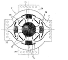
図2は、上部環状鍔部7を上面図で示す概略例示である。環状鍔部7は、実質的にリング状の銅ディスクから構成され、これには、互いに対して向かい合っている2つの電極端子71、72(端子タブ)が外側円周に設けられており、それを経由して加熱電流が環状鍔部7内に供給される。電極端子71、72は、合同電源(図示せず)から供給される。環状鍔部には複数の貫通穴73が設けられており、円周の一部のまわりを半径方向に延在し、中心軸74(長手方向3に対応する)のまわりに対称的に分布される。貫通穴73は、ここではフランジ31の区域に形成され、電極端子71、72によって供給
される加熱電流が、方向矢印75によって表される等しい長さの8つの電流路に分岐され、それによって内側穴77aの区域の「好ましい供給点」76にガイドされ、それとともに環状鍔部が接触チューブ5上に載置される(図1参照)ように配列される。2つの電極端子71、72および貫通穴73の分布およびサイズのおかげで、加熱電流は、図2にしたがって合計8つの好ましい供給点76(「8点供給」)にわたって環状鍔部7に分布される。1つの「好ましい供給点」のみを備えた環状鍔部の実施形態と比較すると、これは、結果として、内側穴77aの区域でより均一な電流密度分布になり、したがって、接触チューブ5の、したがって加熱チューブ2の区域における電流密度の均質的な水平分布になる。
FIG. 2 is a schematic illustration showing the upper
加熱チューブ2の電流密度分布のさらなる均質化は、図2に概略的に示されるように、上部環状鍔部7の電極端子71、72が下部環状鍔部8の電極端子78、79に対して90度ずれているという措置(図1参照)によって達成される。下部環状鍔部8もまた、加熱電流の8点供給用に最適化され、そのため、環状鍔部7、8のずれ配列もまた結果として、90度だけ「好ましい電力供給点」のずれになり、中心軸75に対して回転対称になる。これは結果として、加熱チューブ2内で均一な垂直電流密度分布になり、これは、電流および温度分布の改良された均質化にさらに貢献する。
Further homogenization of the current density distribution of the
酸素が炉チャンバ4内に入るのを回避するために、上記チャンバは、引き抜き加工中に窒素でフラッシュされる。この目的のために、フラッシュリング18(図1)が、図3に示されるように使用される。フラッシュリング18は、ガス入口ノズル81を形成する相互接続銅チューブから構成され、2つの分岐ステージ82、83に分岐され合計4つの二次ライン20になる。二次ライン20の各々は中心で、第3の分岐ステージ85の形成下で、環状セグメント89に終端し、これには、複数のガス出口86が設けられている。環状セグメント89のガス出口85は、加熱チューブ2の内径よりも小さなエンベロープ円形に設けられる。ガス出口85は合同して、実質的に環状断面のガスシャワーを形成する。窒素流れは、ガス出口86から開始して、加熱チューブ2を通って長手方向軸3へ向かい、頂部から底部へ行く。できるだけ均質で薄層の窒素流れを得るために、可能であれば同一であるガス圧力が、ガス出口85には望ましい。これは、すべての二次ライン20が同一長さおよび同一内径を有し、第1の分岐ステージ82とそれぞれの環状セグメント89の開口87との間の距離がすべての二次ライン20で同一である場合に、達成される。
In order to avoid oxygen entering the furnace chamber 4, the chamber is flushed with nitrogen during the drawing process. For this purpose, a flash ring 18 (FIG. 1) is used as shown in FIG. The
1:石英ガラスシリンダ、2:加熱チューブ、3:長手方向軸、4:加熱チャンバ、5:上部接触チューブ、6:下部接触チューブ、7:上部環状鍔部、8:下部環状鍔部、9:冷却チャネル、10:冷却チャネル、11:上部側、12:下部側、13:クランプ装置、14:テンションロッド、16:スペーサー、17:方向矢印、18:フラッシュガスリング、19:ガス出口、20:二次ライン、21:炉ジャケット、22:貫通穴、23:導光板、26:純化石英ウール、27:冷却水入口、28:冷却水入口、29:冷却プレート、30:底部プレート、31:フランジ、71:電極端子、73:貫通穴、74:中心軸、75:中心軸、75:方向矢印、76:供給点、77:電流路、77a:内側穴、78:電極端子、81:ガス入口ノズル、82:分岐ステージ、85:ガス出口、85:分岐ステージ、86:ガス出口、87:開口、89:環状セグメント。 1: quartz glass cylinder, 2: heating tube, 3: longitudinal axis, 4: heating chamber, 5: upper contact tube, 6: lower contact tube, 7: upper annular collar , 8: lower annular collar , 9: Cooling channel, 10: cooling channel, 11: upper side, 12: lower side, 13: clamping device, 14: tension rod, 16: spacer, 17: directional arrow, 18: flash gas ring, 19: gas outlet, 20: Secondary line, 21: furnace jacket, 22: through hole, 23: light guide plate, 26: purified quartz wool, 27: cooling water inlet, 28: cooling water inlet, 29: cooling plate, 30: bottom plate, 31: flange , 71: electrode terminal, 73: through hole, 74: center axis, 75: central axis 75: arrow, 76: feed point, 77: current paths, 77 a: inner hole 78: electrode terminal, 81: Gas inlet nozzle, 82: branch stage, 85: gas outlet, 85: branch stage, 86: gas outlet, 87: opening, 89: annular segment.
Claims (18)
Applications Claiming Priority (1)
| Application Number | Priority Date | Filing Date | Title |
|---|---|---|---|
| PCT/EP2002/000663 WO2003062727A1 (en) | 2002-01-24 | 2002-01-24 | Resistance furnace |
Publications (2)
| Publication Number | Publication Date |
|---|---|
| JP2005515399A JP2005515399A (en) | 2005-05-26 |
| JP4093964B2 true JP4093964B2 (en) | 2008-06-04 |
Family
ID=27589042
Family Applications (1)
| Application Number | Title | Priority Date | Filing Date |
|---|---|---|---|
| JP2003562552A Expired - Fee Related JP4093964B2 (en) | 2002-01-24 | 2002-01-24 | Resistance furnace |
Country Status (9)
| Country | Link |
|---|---|
| US (1) | US7006552B2 (en) |
| EP (1) | EP1468233B1 (en) |
| JP (1) | JP4093964B2 (en) |
| KR (1) | KR100837747B1 (en) |
| CN (1) | CN100371670C (en) |
| AT (1) | ATE503161T1 (en) |
| DE (1) | DE50214980D1 (en) |
| TW (1) | TW200302672A (en) |
| WO (1) | WO2003062727A1 (en) |
Families Citing this family (12)
| Publication number | Priority date | Publication date | Assignee | Title |
|---|---|---|---|---|
| KR101176735B1 (en) * | 2005-07-22 | 2012-08-23 | 지멘스 악티엔게젤샤프트 | Electric arc furnace, method for controlling the same, and method for determining a foam slag height of an electric arc furnace |
| FR2910777B1 (en) * | 2006-12-21 | 2013-07-19 | Revtech | PROCESS FOR THERMALLY TREATING PULVERULENT MATERIALS |
| DE102010025236A1 (en) * | 2010-02-18 | 2011-08-18 | SMS Siemag AG, 40237 | Electrode support arm of a smelting metallurgical furnace |
| JP6385472B2 (en) * | 2014-06-17 | 2018-09-05 | ヘレーウス クオーツ ノース アメリカ エルエルシーHeraeus Quartz North America LLC | Apparatus and method for measuring transparent cylindrical products |
| CN104596265A (en) * | 2014-12-25 | 2015-05-06 | 贵州永兴科技有限公司 | Informationized universal electric furnace having alarming and face recognition functions |
| CN104596273A (en) * | 2014-12-25 | 2015-05-06 | 贵州永兴科技有限公司 | Self-start type all-purpose electric stove switch with functions of count and face recognition |
| CN104596264A (en) * | 2014-12-25 | 2015-05-06 | 贵州永兴科技有限公司 | Informationized all-purpose electric stove with functions of count and fingerprint recognition |
| CN104596280A (en) * | 2014-12-25 | 2015-05-06 | 贵州永兴科技有限公司 | Informationized universal electric furnace having alarming and face recognition functions |
| CN104596263A (en) * | 2014-12-25 | 2015-05-06 | 贵州永兴科技有限公司 | Informationized all-purpose electric stove with functions of count and fingerprint recognition |
| WO2017138087A1 (en) * | 2016-02-09 | 2017-08-17 | 株式会社日立国際電気 | Substrate treatment apparatus and method for manufacturing semiconductor device |
| CN109553276B (en) * | 2017-09-26 | 2021-10-29 | 东旭光电科技股份有限公司 | Platinum channel electric heating device and method |
| US11459626B2 (en) * | 2018-08-10 | 2022-10-04 | American Iron And Steel Institute | Flash ironmaking drop tube furnace system |
Family Cites Families (11)
| Publication number | Priority date | Publication date | Assignee | Title |
|---|---|---|---|---|
| US715509A (en) * | 1902-03-28 | 1902-12-09 | George Westinghouse | End support and circuit-terminal for carbon-tube furnaces. |
| US1023309A (en) * | 1911-08-11 | 1912-04-16 | Hugo Helberger | Electrical resistance furnace. |
| FR500555A (en) * | 1918-06-14 | 1920-03-17 | Morgan Crucible Co | Improvements to electric ovens |
| US2121744A (en) * | 1933-10-20 | 1938-06-21 | Norton Co | Electric furnace |
| US3139474A (en) | 1959-12-21 | 1964-06-30 | Chrysler Corp | High temperature furnace for treating refractory materials with metals and intermetallic compounds |
| US3170018A (en) * | 1960-05-03 | 1965-02-16 | Nuclear Technical Service Corp | High temperature furnace |
| US4549345A (en) | 1981-11-19 | 1985-10-29 | Wilsey Harvey J | Method of making a graphite zig-zag picket heater |
| CN85202601U (en) * | 1985-06-27 | 1986-04-23 | 关东冶金工业株式会社 | Graphite barrel reheating furnace |
| US4703556A (en) * | 1985-11-12 | 1987-11-03 | Ultra Carbon Corporation | Method of making a segmented heater system |
| CN2059437U (en) * | 1989-03-27 | 1990-07-18 | 胡其达 | Resistance stove for drawing tube |
| JP3388306B2 (en) | 1996-02-01 | 2003-03-17 | 株式会社ニッカトー | Electric furnace |
-
2002
- 2002-01-24 KR KR1020047011156A patent/KR100837747B1/en not_active IP Right Cessation
- 2002-01-24 DE DE50214980T patent/DE50214980D1/en not_active Expired - Lifetime
- 2002-01-24 JP JP2003562552A patent/JP4093964B2/en not_active Expired - Fee Related
- 2002-01-24 EP EP02722031A patent/EP1468233B1/en not_active Expired - Lifetime
- 2002-01-24 AT AT02722031T patent/ATE503161T1/en active
- 2002-01-24 US US10/502,485 patent/US7006552B2/en not_active Expired - Lifetime
- 2002-01-24 CN CNB028275527A patent/CN100371670C/en not_active Expired - Lifetime
- 2002-01-24 WO PCT/EP2002/000663 patent/WO2003062727A1/en active Application Filing
-
2003
- 2003-01-21 TW TW092101261A patent/TW200302672A/en unknown
Also Published As
| Publication number | Publication date |
|---|---|
| US7006552B2 (en) | 2006-02-28 |
| US20050069015A1 (en) | 2005-03-31 |
| KR100837747B1 (en) | 2008-06-13 |
| DE50214980D1 (en) | 2011-05-05 |
| TW200302672A (en) | 2003-08-01 |
| JP2005515399A (en) | 2005-05-26 |
| EP1468233B1 (en) | 2011-03-23 |
| WO2003062727A1 (en) | 2003-07-31 |
| ATE503161T1 (en) | 2011-04-15 |
| CN100371670C (en) | 2008-02-27 |
| KR20040077742A (en) | 2004-09-06 |
| CN1618000A (en) | 2005-05-18 |
| EP1468233A1 (en) | 2004-10-20 |
Similar Documents
| Publication | Publication Date | Title |
|---|---|---|
| JP4093964B2 (en) | Resistance furnace | |
| US7173219B2 (en) | Ceramic heaters | |
| JP2007300057A (en) | Substrate support with electrostatic chuck having double temperature zone | |
| US6546760B1 (en) | Optical fiber drawing furnace with a zig zag heating element | |
| JPH06294785A (en) | Mounting device of gas transfer pipe | |
| CN103347639A (en) | Gas-cooled torches for arc-light welding equipment | |
| JP7401654B2 (en) | Semiconductor processing equipment with improved uniformity | |
| CA2011153C (en) | Furnace and process for optical fiber drawing | |
| JPH06227822A (en) | Outflow apparatus for glass preform | |
| US3205343A (en) | Blackbody source | |
| US5184894A (en) | Method of using an immersible air cooled thermocouple | |
| US7082261B2 (en) | Heating stage | |
| JPH0718446A (en) | Heat treating device | |
| JP2009253061A (en) | Substrate support member | |
| CN100493265C (en) | Method of supplying electric current to a tube furnace | |
| JP5655304B2 (en) | Optical fiber drawing furnace and optical fiber drawing method | |
| US3377418A (en) | Small diameter fluid cooled arc-rotating electrode | |
| JP5348447B2 (en) | Cell characterization device | |
| CN113874548A (en) | Substrate base for improved substrate handling | |
| JPH08102445A (en) | Wafer heating device and wafer boat | |
| JP2012089557A (en) | Substrate processing equipment and method for manufacturing semiconductor device | |
| JPH06227837A (en) | Heating oven for spinning optical fiber | |
| JP6829087B2 (en) | Sample holder | |
| US3580977A (en) | Quick-change field coil assembly for use in an electrode having a fluid-cooled arcing surface | |
| CN116669237A (en) | A heating device for photovoltaic semiconductors and a temperature-compensated diffusion furnace |
Legal Events
| Date | Code | Title | Description |
|---|---|---|---|
| A131 | Notification of reasons for refusal |
Free format text: JAPANESE INTERMEDIATE CODE: A131 Effective date: 20071116 |
|
| A521 | Request for written amendment filed |
Free format text: JAPANESE INTERMEDIATE CODE: A523 Effective date: 20080201 |
|
| TRDD | Decision of grant or rejection written | ||
| A01 | Written decision to grant a patent or to grant a registration (utility model) |
Free format text: JAPANESE INTERMEDIATE CODE: A01 Effective date: 20080227 |
|
| A61 | First payment of annual fees (during grant procedure) |
Free format text: JAPANESE INTERMEDIATE CODE: A61 Effective date: 20080304 |
|
| FPAY | Renewal fee payment (event date is renewal date of database) |
Free format text: PAYMENT UNTIL: 20110314 Year of fee payment: 3 |
|
| R150 | Certificate of patent or registration of utility model |
Ref document number: 4093964 Country of ref document: JP Free format text: JAPANESE INTERMEDIATE CODE: R150 Free format text: JAPANESE INTERMEDIATE CODE: R150 |
|
| FPAY | Renewal fee payment (event date is renewal date of database) |
Free format text: PAYMENT UNTIL: 20110314 Year of fee payment: 3 |
|
| FPAY | Renewal fee payment (event date is renewal date of database) |
Free format text: PAYMENT UNTIL: 20120314 Year of fee payment: 4 |
|
| R250 | Receipt of annual fees |
Free format text: JAPANESE INTERMEDIATE CODE: R250 |
|
| FPAY | Renewal fee payment (event date is renewal date of database) |
Free format text: PAYMENT UNTIL: 20120314 Year of fee payment: 4 |
|
| FPAY | Renewal fee payment (event date is renewal date of database) |
Free format text: PAYMENT UNTIL: 20130314 Year of fee payment: 5 |
|
| R250 | Receipt of annual fees |
Free format text: JAPANESE INTERMEDIATE CODE: R250 |
|
| FPAY | Renewal fee payment (event date is renewal date of database) |
Free format text: PAYMENT UNTIL: 20130314 Year of fee payment: 5 |
|
| FPAY | Renewal fee payment (event date is renewal date of database) |
Free format text: PAYMENT UNTIL: 20140314 Year of fee payment: 6 |
|
| R250 | Receipt of annual fees |
Free format text: JAPANESE INTERMEDIATE CODE: R250 |
|
| R250 | Receipt of annual fees |
Free format text: JAPANESE INTERMEDIATE CODE: R250 |
|
| R250 | Receipt of annual fees |
Free format text: JAPANESE INTERMEDIATE CODE: R250 |
|
| R250 | Receipt of annual fees |
Free format text: JAPANESE INTERMEDIATE CODE: R250 |
|
| R250 | Receipt of annual fees |
Free format text: JAPANESE INTERMEDIATE CODE: R250 |
|
| R250 | Receipt of annual fees |
Free format text: JAPANESE INTERMEDIATE CODE: R250 |
|
| R250 | Receipt of annual fees |
Free format text: JAPANESE INTERMEDIATE CODE: R250 |
|
| R250 | Receipt of annual fees |
Free format text: JAPANESE INTERMEDIATE CODE: R250 |
|
| LAPS | Cancellation because of no payment of annual fees |