JP4057293B2 - Document presence / absence detection sensor and document size detection sensor - Google Patents
Document presence / absence detection sensor and document size detection sensor Download PDFInfo
- Publication number
- JP4057293B2 JP4057293B2 JP2001396020A JP2001396020A JP4057293B2 JP 4057293 B2 JP4057293 B2 JP 4057293B2 JP 2001396020 A JP2001396020 A JP 2001396020A JP 2001396020 A JP2001396020 A JP 2001396020A JP 4057293 B2 JP4057293 B2 JP 4057293B2
- Authority
- JP
- Japan
- Prior art keywords
- light
- detection sensor
- light emitting
- document
- emitting element
- Prior art date
- Legal status (The legal status is an assumption and is not a legal conclusion. Google has not performed a legal analysis and makes no representation as to the accuracy of the status listed.)
- Expired - Fee Related
Links
Images


Landscapes
- Length Measuring Devices By Optical Means (AREA)
- Geophysics And Detection Of Objects (AREA)
- Holders For Sensitive Materials And Originals (AREA)
- Optical Systems Of Projection Type Copiers (AREA)
- Facsimile Scanning Arrangements (AREA)
Description
【0001】
【発明の属する技術分野】
この発明は、一般に、画像読取装置に用いる原稿の有無検出センサに関するものであり、より特定的には、画像読取装置のセンサ部の薄型化を図ることができるように改良された原稿の有無検出センサに関する。この発明は、また、画像読取装置のセンサ部の薄型化を図ることができるように改良された原稿サイズ検出センサに関する。
【0002】
【従来の技術】
原稿の有無検出センサシステムの方式には、三角測量方式のものと、反射光量比較方式のものとがある。
【0003】
図8は、反射光量比較方式の複写機の概念図である。反射光量比較方式では、反射物からの反射光量の大小により原稿の有無を判断する。しかし、この方法は、原稿と上蓋との反射光量の差で原稿の有無を識別しており、それらの区別が不可能である。また、上蓋の位置によっては誤検知が生ずるおそれがある。また、原稿の反射率の影響を受けるという問題がある。これに対して、三角測量方式のものはこのような問題点がない。
【0004】
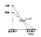
図9は、三角測量方式の原稿の有無検出センサの概念図である。三角測量方式は、もともと距離を測定するものであるが、これを、原稿の有無検出センサに応用することができる。三角測量方式は、反射物までの距離に着目して、原稿の有無を判断する。
【0005】
この方式によると、原稿と上蓋の距離の差により、両者の区別が可能となる。この方式を採用すると、反射光量に関係なく、スポットの当る位置により、原稿の有無を判断することができる。
【0006】
図10は、センサの配置例を示す例である。このようにビームを複数個設けることにより、原稿の有無の検知だけでなく、用紙のサイズを検知することができる。用紙サイズを検知した結果を、表1に示す。
【0007】
【表1】

本発明は、反射光量比較方式のもに比べて、上記多くの利点を有する三角測量方式の原稿の有無検出センサおよび原稿サイズ検出センサに関する。
【0009】
ここで、三角測量方式の原理について説明する。図11を参照して、近距離と遠距離とでは反射されて返ってくる赤外光の、位置検出素子(PSD)に入射する位置が異なる。それによって、比I1、I2の電流の値も変わる。
【0010】
図12は、PSDの概念図である。図12を参照して、入射光が、たとえば、6:4に区分された位置Aに照射されるとすれば、出力値V0は、I1/I2の比(=4/6)のみに依存し、測定対象物の反射の影響による因子が全く現われてこない。これが、反射光量比較方式のものに比べて特に優れている点である。
【0011】
図13は、出力と距離との関係を示す図である。出力を測定することによって、距離が測定される。
【0012】
三角測量方式は、距離を測定するためのものであるが、これを、上述のように原稿の有無検出センサおよび原稿サイズ検出センサに応用することが可能であり、原稿の有無検出センサおよび原稿サイズ検出センサに応用すると、次のような利点が生じる。
【0013】
すなわち、位置検出素子(PSD)の採用により、原稿の色(反射率)による影響を受けず、高精度に原稿の有無検出または原稿サイズの検知が可能となる。また、原稿サイズ検出センサのシリーズ化(1ビーム/3ビーム)で、各原稿サイズ検出センサの組合せにより、ユーザにてセンサの使用数の削減が可能となる。
【0014】
図14は、三角測量方式の原稿サイズ検出センサを用いる複写機の概念図である。複写機は、上蓋1と本体部2とを備える。本体部2の上方には、光源ランプ3が設けられている。光源ランプ3は、水平方向に移動する。本体部2はレンズ10を備える。原稿の有無検出センサまたは原稿サイズ検出センサ4は、光源ランプ3の通路の下側とレンズ10の上にそれぞれ設けられる。
【0015】
本体部2は、給紙トレイ5を備える。従来は、排紙トレイ6は、点線で示す部分に取付けられていたが、近年は、本体部2の上方部に設けられるようになった。
【0016】
【発明が解決しようとする課題】
さて、現在、複写機、複合FAX等は小型化している。この小型化のために、複写機の高さを低くすることが求められている。複写機の高さを低くするために、光源ランプ3と原稿の有無検出センサまたは原稿サイズ検出センサ4が収容される部分を、薄くするという要望が出されている。そのために、原稿の有無検出センサおよび原稿サイズ検出センサの小型化が必要となってきている。
【0017】
しかしながら、従来の三角測量方式原稿の有無検出センサおよび原稿サイズ検出センサを用いる場合には、この小型化が不可能であった。これについて、説明する。
【0018】
図15および図16は、上記小型化が困難であることを説明するための図である。
【0019】
図15を参照して、プリント基板7の上に、発光素子8と受光素子9が設けられている。発光素子8の上方には、発光側レンズ10が設けられている。受光素子9の上方には、受光側レンズ11が設けられている。これらの部品は、ケース12で固定されている。
【0020】
発光素子8から出た光は、発光側レンズ10を通って、ガラス板15および原稿24に向かう。三角測量方式は発光素子8からの光をガラス板15および原稿24に向けて投光し、ガラス板15と原稿24の界面から乱反射される反射光13を受光素子9で受光することによって、原稿24の有無を検出するものである。本明細書においては、上記原稿24を対象物と呼び、上記ガラス板15を非対象物と呼ぶ。
【0021】
原稿の有無検出センサの小型化は、図15に示すように発光光軸をガラス面に垂直に配置する、すなわち、プリント基板7の面とガラス板15の面を平行にすることにより可能となる。
【0022】
しかしながら、プリント基板7の水平面とガラス板15の水平面が平行にされている場合には、ガラス板15に投光され、正反射し、受光素子9に向かう正反射光14が、受光素子9に入射されてしまう。正反射光14と原稿24からの乱反射光13が重なって、受光素子9で検出されると、原稿24の有無の判定は不可能となる。正反射光成分は誤検出の原因となる。
【0023】
そこでこのような問題点を解決するために、図16を参照して、プリント基板7を、ガラス15の面に対して、角度を付けて固定している。このように配置すると、発光素子8から出た光の成分のうち、ガラス板15に投光され、正反射する正反射光14は、受光素子9に入射しなくなる。これによって、ガラス板15と原稿24の界面から乱反射される反射光のみを受光素子9で受光することができる。そこで、原稿24の有無を正確に、判定することができる。
【0024】
しかしながら、プリント基板7を傾けて配置するので、図示しているように本来Bの厚みであったセンサ部分が、Bよりも大きいAを持つ厚みとなり、センサ部を薄くすることができないという問題点があった。
【0025】
この発明は、上記のような問題点を解決するためになされたもので、三角測量方式の原稿の有無検出センサおよび原稿サイズ検出センサにおいて、プリント基板とガラス面を、平行にすることができるように改良された原稿の有無検出センサおよび原稿サイズ検出センサを提供することを目的とする。
【0026】
この発明の他の目的は、画像読取装置の高さを低くすることができるように改良された原稿の有無検出センサおよび原稿サイズ検出センサを提供することにある。
【0028】
【課題を解決するための手段】
この発明の第1の局面に従う原稿有無検出センサは、発光素子からの光をガラス板の上に載せられた対象物に投光し、該対象物から乱反射される反射光を受光素子で受光することにより、対象物の有無を検出する原稿有無検出センサに係る。当該原稿有無検出センサは、ガラス板と平行に配置されたプリント基板を備える。上記プリント基板の上に互いに離されて発光素子と受光素子が設けられている。上記発光素子と上記対象物の間に発光側レンズが設けられている。上記受光素子と前記対象物の間に受光側レンズが設けられている。上記発光素子と上記対象物の間に、前記発光素子から出る光成分の内、前記ガラス板に投光され、正反射し、正反射光となって前記受光素子に向かう光成分を遮断する遮光手段が設けられている。
【0029】
この発明の第2の局面に従う原稿有無検出センサは、上記第1の局面に従う原稿の有無検出センサにおいて、上記遮光手段は、上記発光側レンズの上に設けられた、該発光側レンズから出てくる光の一部を遮断するスリット形状の遮光部材を含む。
【0030】
この発明の第3の局面に従う原稿有無検出センサは、上記スリット形状の遮光部材の大きさは、上記正反射光になる光成分を完全に遮断することができるように選ばれている。
【0031】
この発明の第4の局面に従う原稿有無検出センサは、上記第1の局面に従う原稿の有無ズ検出センサにおいて、上記遮光手段は、上記発光側レンズの上に設けられた、該発光側レンズから出てくる光の一部を遮断するピンホール形状の遮光部材を含む。
【0032】
この発明の第5の局面に従う原稿の有無検出センサは、上記第4の局面に従う原稿の有無検出センサにおいて、上記ピンホール形状の遮光部材のピンホールの大きさは、上記正反射光になる光成分を完全に遮断することができるように選ばれている。
【0033】
この発明の第6の局面に従う原稿の有無検出センサは、上記第1の局面に従う原稿の有無検出センサにおいて、上記遮光手段は、上記発光素子から出る実質的に垂直に上方向に向かう光のみを上記発光側レンズに入射させるように、上記発光素子を樹脂でモールドすることにより形成されている。
【0037】
この発明の第7の局面に従う原稿サイズ検出センサは、発光素子からの光をガラス板の上に載せられた対象物に投光し、該対象物から乱反射される反射光を受光素子で受光することにより、対象物のサイズを検出する原稿サイズ検出センサにかかる。当該原稿サイズ検出センサはガラス板と平行に配置されたプリント基板を備える。上記プリント基板の上に互いに離されて発光素子と受光素子が設けられている。上記発光素子と上記対象物の間に発光側レンズが設けられている。上記受光素子と上記対象物の間に受光側レンズが設けられている。上記発光素子と上記対象物の間に、前記発光素子から出る光成分の内、前記ガラス板に投光され、正反射し、正反射光となって前記受光素子に向かう光成分を遮断する遮光手段が設けられている。上記発光素子は複数設けられており、前記遮光手段は、上記対象物とそれぞれの上記発光素子との間に設けられている。
【0038】
この発明の第8の局面に従う原稿サイズ検出センサは、上記第7の局面に従う原稿サイズ検出センサにおいて、上記受光側レンズの上方にはトロイダルレンズが設けられている。
【0039】
この発明の第9の局面に従う原稿サイズ検出センサは、上記第7または8の局面に従う原稿サイズ検出センサにおいて、一の発光素子と受光素子は1パッケージとされ、他の発光素子は上記プリント基板に取付けられている。
【0044】
【発明の実施の形態】
以下、この発明の実施の形態を図を用いて説明する。
【0045】
実施の形態1
図1(a)、(b)、(c)および(d)は、実施の形態1に係る原稿の有無検出センサを説明するための概念図である。
【0046】
図1(a)を参照して、従来の原稿の有無検出センサを、プリント基板7の面とガラス板15の面が互いに平行になるように配置した場合、正反射光14が受光素子9に入射する。したがって、プリント基板7の面とガラス板15の面を平行にすることにより、装置の小型化を図ることができるが、正反射光14が受光素子9に入射してしまう結果、正確に、原稿の有無を判定することができなくなる。
【0047】
なお、図1(b)は、図1(a)の中で図示されている原稿の有無検出センサの平面図である。
【0048】
上記のような問題点を解決するために、本実施の形態がなされた。本実施の形態では、図1(c)を参照して、発光側レンズ10の上に、発光側レンズ10から出てくる光の一部を遮断する、スリット形状の遮光部材17が設けられている。遮光部材17の大きさは、発光素子8から出てくる光成分のうち、正反射光14になる光成分を完全に遮断することができるように選ばれている。図中、点線で示された光は遮光されて、実際には現れてこない光である。なお、図1(d)は図1(c)に示す原稿の有無検出センサの平面図である。遮光部材17は、ケース12の一部を発光素子側レンズ10の上に延在するようにして、形成される。
【0049】
このように構成することにより、プリント基板7の面とガラス板15の面を平行にすることができ、ひいては、画像読取装置のセンサ部分の厚みを薄くすることができる。その結果、画像読取装置の小型化を図ることができる。
【0050】
実施の形態2
図2は、実施の形態2に係る原稿の有無検出センサを説明するための概念図である。
【0051】
図2(a)を参照して、発光側レンズ10の上に、発光側レンズ10から出てくる光の一部を遮断するピンホール18aを有する遮光部材18が設けられる。遮光部材18は、ケース12と一体的に形成される。このように構成することにより、発光素子8から出てくる光成分のうち、正反射光14になる光成分を完全に遮断することができ、それによって、正反射光14が受光素子9に入射しないようすることができる。図中、点線で示された光14は遮光されて、実際には現れてこない光である。これにより、プリント基板7の面とガラス板15の面を平行にすることができ、それによって、画像読取装置のセンサ部分の厚みを薄くすることができる。その結果、画像読取装置の小型化を図ることができる。なお、図2(b)は図2の中で示された原稿の有無検出センサの平面図である。
【0052】
実施の形態3
図3は、実施の形態3に係る原稿の有無検出センサを説明するための概念図である。
【0053】
図3(a)を参照して、従来の発光チップ19は垂直上方向のみならず、斜め横方向にも光を投光する。したがって、正反射光14が受光素子9に入射する。
【0054】
そこで、図3(b)に示すように、本実施の形態では、発光チップ19から出る実質的に垂直上方向に向かう光のみを発光側レンズ10に入射させるように、発光チップ19を樹脂20でモールドする。具体的には、図3(c)(発光チップ19の平面図)を参照して、窓21を形成するように、発光チップ19を樹脂20で被覆する。
【0055】
このようにすることによって、発光チップ19から出てくる光成分のうち、正反射光14になる光成分を完全に遮断することができ、それによって、正反射光が受光素子に入射しないようすることができる。ひいては、プリント基板の面とガラス板15の面を平行にすることができ、それによって、画像読取装置のセンサ部分の厚みを薄くすることができる。その結果、画像読取装置の小型化を図ることができる。
【0056】
実施の形態4
図4は、実施の形態4に係る原稿サイズ検出センサを説明するための概念図である。このように複数の発光部を設けることにより、原稿サイズの検出をすることができる。
【0057】
図4を参照して、原稿サイズ検出センサは、複数個の発光素子8a,8b,8cと受光部を備える。このように複数の発光素子8a,8b,8cを隣接させて設けることにより、複数の隣接したポイントを検出することができる。発光素子8a,8b,8cには、実施の形態1〜3に係る工夫がなされている。受光部にはトロイダルレンズ21が設けられている。トロイダルレンズ21を設けることにより、発光素子8a,8b,8cから出た光を効率的に受光素子に集めることができる。
【0058】
実施の形態5
図5は、実施の形態5に係る原稿サイズ検出センサを説明するための概念図である。
【0059】
図5(a)に示すように、複数の隣接したポイントを検出したい場合、複数の原稿サイズ検出センサを隣接させれば、検出することが可能となるが、コストがかかってしまう。
【0060】
そこで、図5(b)を参照して、1受光部と複数発光部を一体化して、1つの原稿サイズ検出センサを作成することによりコストダウンを図ることができる。
【0061】
実施の形態6
図6は、実施の形態6に係る原稿サイズ検出センサを説明するための平面図である。
【0062】
実施の形態5では、3つの発光部と受光部を一体化する場合を例示したが、この発明はこれに限られるものではない。
【0063】
すなわち、図5(b)を参照して、複数発光部のビームピッチl1、l2が異なる場合、ビームピッチごとにレンズ付きケース金型を製作しなければならない。例えば、3ビームタイプのビームピッチが33mmタイプ、26mmタイプ、21mmタイプ等の種類がある場合、各ビームピッチでのレンズ付きケース金型を必要とする。これは、コストがかかりすぎる。
【0064】
そこで、図6に示す本実施の形態のように、1つの発光素子8bと受光素子9を一体化して形成する。発光素子8aと8cは、それぞれ別々に製作し、これらを発光素子8bと受光素子9が一体化して形成されたプリント基板に、たとえばビス止めによって取付ける。このように構成することにより、ビームピッチl1およびl2を種々変えた原稿サイズ検出センサを安価に作ることができる。
【0065】
実施の形態7
図7は、実施の形態7に係る原稿の有無検出センサを説明するための平面図である。
【0066】
図7(a)を参照して、発光側レンズ10の中心軸と発光素子8の中心軸が一致した場合、正反射光14が受光素子に入射してしまう。なお、図7(b)は図7(a)の中で示される原稿の有無検出センサの平面図である。
【0067】
そこで、本実施の形態によれば、図7(c)を参照して、発光素子8の中心軸8aを、発光側レンズ10の中心軸10aから受光素子9側にずらして形成する。このように構成することにより、正反射光14のもとになる発光素子から出る光の成分はケース12によって遮断される。それによって、正反射光が受光素子に入射しないようすることができる。ひいては、プリント基板7の面とガラス板15の面を平行にすることができ、それによって、画像読取装置のセンサ部分の厚みを薄くすることができる。その結果、画像読取装置の小型化を図ることができる。なお、図7(d)は、図7(c)の中で示される原稿の有無検出センサの平面図である。
【0068】
発光側レンズ10の中心軸10aのずらせ方は、上記実施の形態に限られるものでなく、正反射光が受光素子に入射しないようすることができれば、いずれの方向にずらせてもよい。要するに、発光素子から発せられ発光側レンズを通過した光の光軸が、プリント基板平面に対して、垂直にならないように傾けられているように構成されていればよい。これは、原稿有無検出センサ、原稿サイズ検出センサのいずれの場合においても効果を奏する。
【0069】
なお上記実施の形態では、本発明に係る原稿の有無検出センサおよび原稿サイズ検出センサを、複写機に用いる場合を例示したが、この発明はこれに限られるものでなく、マルチファンクション化した複写機、その他の画像読取装置にも適用することができる。
【0070】
今回開示された実施の形態はすべての点で例示であって制限的なものではないと考えられるべきである。本発明の範囲は上記した説明ではなくて特許請求の範囲によって示され、特許請求の範囲と均等の意味および範囲内でのすべての変更が含まれることが意図される。
【0071】
【発明の効果】
以上説明したとおり、この発明に係る原稿の有無検出センサおよび原稿サイズ検出センサによれば、特性に影響を及ぼす正反射光成分を減少させることができ、特性改善を図ることができる。また、本発明に係る画像読取装置によれば、高さ方向の小型化を図ることができる。
【図面の簡単な説明】
【図1】 実施の形態1に係る原稿の有無検出センサを説明するための概念図である。
【図2】 実施の形態2に係る原稿の有無検出センサを説明するための概念図である。
【図3】 実施の形態3に係る原稿の有無検出センサを説明するための概念図である。
【図4】 実施の形態4に係る原稿サイズ検出センサを説明するための概念図である。
【図5】 実施の形態5に係る原稿サイズ検出センサを説明するための概念図である。
【図6】 実施の形態6に係る原稿サイズ検出センサを説明するための概念図である。
【図7】 実施の形態7に係る原稿の有無検出センサを説明するための概念図である。
【図8】 従来の反射光量比較方式の原稿の有無検出センサを説明するための概念図である。
【図9】 三角測量方式の原稿の有無検出センサを説明するための概念図である。
【図10】 センサの配置例を示す図である。
【図11】 三角測量方式の原理を詳しく説明するための概念図である。
【図12】 従来の三角測量方式の原理をさらに詳しく説明するための他の概念図である。
【図13】 従来の三角測量方式における、出力と距離との関係を示す図である。
【図14】 複写機の概念図である。
【図15】 三角測量方式の問題点を示す図である。
【図16】 三角測量方式の問題点を改良させた従来の装置の概念図である。
【符号の説明】
7 プリント基板、8 発光素子、9 受光素子、14 正反射光、15 ガラス板、24 原稿。[0001]
BACKGROUND OF THE INVENTION
BACKGROUND OF THE
[0002]
[Prior art]
There are two types of sensor systems for detecting the presence / absence of a document: a triangulation method and a reflected light amount comparison method.
[0003]
FIG. 8 is a conceptual diagram of a reflected light amount comparison type copying machine. In the reflected light amount comparison method, the presence / absence of a document is determined based on the amount of reflected light from a reflecting object. However, in this method, the presence or absence of the document is identified by the difference in the amount of reflected light between the document and the upper lid, and it is impossible to distinguish them. In addition, there is a risk of erroneous detection depending on the position of the upper lid. There is also a problem of being affected by the reflectance of the document. In contrast, the triangulation method does not have such a problem.
[0004]
FIG. 9 is a conceptual diagram of a triangulation type document presence / absence detection sensor. The triangulation method originally measures distance, but this can be applied to a document presence / absence detection sensor. In the triangulation method, the presence or absence of a document is determined by paying attention to the distance to the reflecting object.
[0005]
According to this method, the difference between the original and the upper lid can be distinguished from each other. When this method is employed, it is possible to determine the presence or absence of a document from the position where the spot hits regardless of the amount of reflected light.
[0006]
FIG. 10 shows an example of sensor arrangement. By providing a plurality of beams in this way, not only the presence / absence of a document but also the size of a sheet can be detected. Table 1 shows the result of detecting the paper size.
[0007]
[Table 1]
The present invention relates to a triangulation type document presence / absence detection sensor and a document size detection sensor having the above-mentioned many advantages over a reflected light amount comparison type.
[0009]
Here, the principle of the triangulation method will be described. Referring to FIG. 11, the position of incident infrared light that is reflected and returned to the position detection element (PSD) differs between the short distance and the long distance. Thereby, the current values of the ratios I 1 and I 2 also change.
[0010]
FIG. 12 is a conceptual diagram of PSD. Referring to FIG. 12, if the incident light is irradiated to position A divided into 6: 4, for example, output value V 0 is only the ratio of I 1 / I 2 (= 4/6). Dependent on the measurement, no factors appear due to the reflection of the measurement object. This is particularly superior to the reflected light amount comparison method.
[0011]
FIG. 13 is a diagram illustrating the relationship between output and distance. The distance is measured by measuring the output.
[0012]
The triangulation method is for measuring a distance, and can be applied to the document presence / absence detection sensor and the document size detection sensor as described above. When applied to a detection sensor, the following advantages arise.
[0013]
That is, by using the position detection element (PSD), it is possible to detect the presence or absence of the document or the document size with high accuracy without being affected by the color (reflectance) of the document. Further, with the series of document size detection sensors (1 beam / 3 beams), the number of sensors used can be reduced by the user by combining each document size detection sensor.
[0014]
FIG. 14 is a conceptual diagram of a copying machine using a triangulation document size detection sensor. The copying machine includes an
[0015]
The
[0016]
[Problems to be solved by the invention]
Now, copiers, complex FAX machines, etc. are downsized. For this miniaturization, it is required to reduce the height of the copying machine. In order to reduce the height of the copying machine, there is a demand for thinning a portion in which the
[0017]
However, in the case of using the conventional triangulation type document presence / absence detection sensor and document size detection sensor, it is impossible to reduce the size. This will be described.
[0018]
15 and 16 are diagrams for explaining that it is difficult to reduce the size.
[0019]
Referring to FIG. 15, light emitting
[0020]
The light emitted from the
[0021]
The document presence / absence detection sensor can be downsized by arranging the light emitting optical axis perpendicular to the glass surface as shown in FIG. 15, that is, by making the surface of the printed
[0022]
However, when the horizontal plane of the printed
[0023]
Therefore, in order to solve such a problem, the printed
[0024]
However, since the printed
[0025]
The present invention has been made to solve the above-described problems. In the triangulation type document presence / absence detection sensor and document size detection sensor, the printed circuit board and the glass surface can be made parallel to each other. It is an object of the present invention to provide an improved document presence / absence detection sensor and document size detection sensor.
[0026]
Another object of the present invention is to provide a document presence / absence detection sensor and a document size detection sensor which are improved so as to reduce the height of an image reading apparatus.
[0028]
[Means for Solving the Problems]
A document presence / absence detection sensor according to a first aspect of the present invention projects light from a light emitting element onto an object placed on a glass plate , and receives reflected light diffusely reflected from the object by a light receiving element. Thus, the present invention relates to a document presence / absence detection sensor for detecting the presence / absence of an object. The document presence / absence detection sensor includes a printed circuit board arranged in parallel with the glass plate . A light emitting element and a light receiving element are provided apart from each other on the printed board. A light emitting side lens is provided between the light emitting element and the object. A light receiving side lens is provided between the light receiving element and the object. Among the light components emitted from the light emitting element, the light is projected onto the glass plate between the light emitting element and the object, and is regularly reflected to block the light component directed to the light receiving element as regular reflected light. Means are provided.
[0029]
The document presence / absence detection sensor according to the second aspect of the present invention is the document presence / absence detection sensor according to the first aspect, wherein the light shielding means is provided on the light emitting side lens provided on the light emitting side lens. It includes a slit-shaped light blocking member that blocks part of the incoming light.
[0030]
In the document presence / absence detection sensor according to the third aspect of the present invention, the size of the slit-shaped light shielding member is selected so that the light component that becomes the regular reflection light can be completely blocked.
[0031]
A document presence / absence detection sensor according to a fourth aspect of the present invention is the document presence / absence detection sensor according to the first aspect, wherein the light shielding means is provided on the light emitting side lens provided on the light emitting side lens. It includes a pinhole-shaped light shielding member that blocks part of the incoming light.
[0032]
The document presence / absence detection sensor according to the fifth aspect of the present invention is the document presence / absence detection sensor according to the fourth aspect, wherein the pinhole size of the pinhole-shaped light blocking member is the light that becomes the regular reflection light. The ingredients are chosen so that they can be completely blocked.
[0033]
The document presence / absence detection sensor according to a sixth aspect of the present invention is the document presence / absence detection sensor according to the first aspect, wherein the light shielding means emits only light emitted from the light emitting element substantially vertically upward. The light emitting element is formed by molding with a resin so as to be incident on the light emitting side lens.
[0037]
A document size detection sensor according to a seventh aspect of the present invention projects light from a light emitting element onto an object placed on a glass plate , and receives reflected light irregularly reflected from the object by a light receiving element. Thus, the document size detection sensor for detecting the size of the object is applied. The document size detection sensor includes a printed circuit board arranged in parallel with the glass plate . A light emitting element and a light receiving element are provided apart from each other on the printed board. A light emitting side lens is provided between the light emitting element and the object. A light receiving side lens is provided between the light receiving element and the object. Among the light components emitted from the light emitting element, the light is projected onto the glass plate between the light emitting element and the object, and is regularly reflected to block the light component directed to the light receiving element as regular reflected light. Means are provided. A plurality of the light emitting elements are provided, and the light shielding means is provided between the object and each of the light emitting elements .
[0038]
An original document size detection sensor according to an eighth aspect of the present invention is the original document size detection sensor according to the seventh aspect, wherein a toroidal lens is provided above the light receiving side lens.
[0039]
An original size detection sensor according to a ninth aspect of the present invention is the original size detection sensor according to the seventh or eighth aspect, wherein one light emitting element and a light receiving element are provided in one package, and the other light emitting element is provided on the printed circuit board. Installed.
[0044]
DETAILED DESCRIPTION OF THE INVENTION
Embodiments of the present invention will be described below with reference to the drawings.
[0045]
FIGS. 1A, 1 </ b> B, 1 </ b> C, and 1 </ b> D are conceptual diagrams for explaining a document presence / absence detection sensor according to the first embodiment.
[0046]
Referring to FIG. 1A, when a conventional document presence / absence detection sensor is arranged so that the surface of the printed
[0047]
FIG. 1B is a plan view of the document presence / absence detection sensor shown in FIG.
[0048]
The present embodiment has been made to solve the above problems. In the present embodiment, referring to FIG. 1C, a slit-shaped
[0049]
By configuring in this way, the surface of the printed
[0050]
FIG. 2 is a conceptual diagram for explaining a document presence / absence detection sensor according to the second embodiment.
[0051]
Referring to FIG. 2A, a
[0052]
FIG. 3 is a conceptual diagram for explaining a document presence / absence detection sensor according to the third embodiment.
[0053]
Referring to FIG. 3A, the conventional
[0054]
Therefore, as shown in FIG. 3B, in the present embodiment, the
[0055]
By doing in this way, the light component which becomes the
[0056]
FIG. 4 is a conceptual diagram for explaining a document size detection sensor according to the fourth embodiment. Thus, by providing a plurality of light emitting units, it is possible to detect the document size.
[0057]
Referring to FIG. 4, the document size detection sensor includes a plurality of
[0058]
Embodiment 5
FIG. 5 is a conceptual diagram for explaining a document size detection sensor according to the fifth embodiment.
[0059]
As shown in FIG. 5A, when it is desired to detect a plurality of adjacent points, if a plurality of document size detection sensors are adjacent to each other, they can be detected, but the cost is increased.
[0060]
Therefore, referring to FIG. 5B, it is possible to reduce the cost by integrating one light receiving portion and a plurality of light emitting portions to create one original size detection sensor.
[0061]
FIG. 6 is a plan view for explaining the document size detection sensor according to the sixth embodiment.
[0062]
In the fifth embodiment, the case where the three light emitting units and the light receiving unit are integrated is illustrated, but the present invention is not limited to this.
[0063]
That is, referring to FIG. 5B, when the beam pitches l 1 and l 2 of the plurality of light emitting units are different, a case mold with a lens must be manufactured for each beam pitch. For example, when there are three beam types such as a 33 mm type, a 26 mm type, and a 21 mm type, the lens mold with lens at each beam pitch is required. This is too expensive.
[0064]
Therefore, as in the present embodiment shown in FIG. 6, one
[0065]
FIG. 7 is a plan view for explaining the document presence / absence detection sensor according to the seventh embodiment.
[0066]
With reference to FIG. 7A, when the central axis of the light emitting
[0067]
Therefore, according to the present embodiment, with reference to FIG. 7C, the central axis 8a of the
[0068]
The method of shifting the
[0069]
In the above embodiment, the case where the document presence / absence detection sensor and the document size detection sensor according to the present invention are used in a copying machine is exemplified. However, the present invention is not limited to this, and a multifunctional copying machine is used. The present invention can also be applied to other image reading apparatuses.
[0070]
The embodiment disclosed this time should be considered as illustrative in all points and not restrictive. The scope of the present invention is defined by the terms of the claims, rather than the description above, and is intended to include any modifications within the scope and meaning equivalent to the terms of the claims.
[0071]
【The invention's effect】
As described above, according to the document presence / absence detection sensor and document size detection sensor according to the present invention, it is possible to reduce the specularly reflected light component that affects the characteristics and to improve the characteristics. In addition, according to the image reading apparatus of the present invention, it is possible to reduce the size in the height direction.
[Brief description of the drawings]
FIG. 1 is a conceptual diagram for explaining a document presence / absence detection sensor according to a first embodiment.
FIG. 2 is a conceptual diagram for explaining a document presence / absence detection sensor according to a second embodiment.
FIG. 3 is a conceptual diagram for explaining a document presence / absence detection sensor according to a third embodiment.
FIG. 4 is a conceptual diagram for explaining a document size detection sensor according to a fourth embodiment.
FIG. 5 is a conceptual diagram for explaining a document size detection sensor according to a fifth embodiment.
FIG. 6 is a conceptual diagram for explaining a document size detection sensor according to a sixth embodiment.
FIG. 7 is a conceptual diagram for explaining a document presence / absence detection sensor according to a seventh embodiment.
FIG. 8 is a conceptual diagram for explaining a document presence / absence detection sensor of a conventional reflected light amount comparison method.
FIG. 9 is a conceptual diagram for explaining a document presence / absence detection sensor of a triangulation method.
FIG. 10 is a diagram illustrating an arrangement example of sensors.
FIG. 11 is a conceptual diagram for explaining in detail the principle of the triangulation method.
FIG. 12 is another conceptual diagram for explaining the principle of the conventional triangulation method in more detail.
FIG. 13 is a diagram showing the relationship between output and distance in a conventional triangulation method.
FIG. 14 is a conceptual diagram of a copying machine.
FIG. 15 is a diagram showing problems of the triangulation method.
FIG. 16 is a conceptual diagram of a conventional apparatus in which the problems of the triangulation method are improved.
[Explanation of symbols]
7 Printed circuit board, 8 Light emitting element, 9 Light receiving element, 14 Regular reflection light, 15 Glass plate, 24 Original.
Claims (9)
前記ガラス板と平行に配置されたプリント基板と、
前記プリント基板の上に互いに離されて設けられた発光素子と受光素子と、
前記発光素子と前記対象物の間に設けられた発光側レンズと、
前記受光素子と前記対象物の間に設けられた受光側レンズと、
前記発光素子と前記対象物の間に設けられ、前記発光素子から出る光成分の内、前記ガラス板に投光され、正反射し、正反射光となって前記受光素子に向かう光成分を遮断する遮光手段と、を備えた原稿有無検出センサ。A document presence / absence detection sensor that detects the presence / absence of an object by projecting light from a light emitting element onto an object placed on a glass plate and receiving reflected light diffusely reflected from the object by a light receiving element. Because
A printed circuit board arranged in parallel with the glass plate ;
A light-emitting element and a light-receiving element provided on the printed circuit board apart from each other;
A light emitting side lens provided between the light emitting element and the object;
A light receiving side lens provided between the light receiving element and the object;
Of the light components that are provided between the light emitting element and the object and are emitted from the light emitting element, the light component is projected onto the glass plate , is specularly reflected, and is converted into specularly reflected light to block the light component toward the light receiving element. A document presence / absence detection sensor.
前記ガラス板と平行に配置されたプリント基板と、
前記プリント基板の上に互いに離されて設けられた発光素子と受光素子と、
前記発光素子と前記対象物の間に設けられた発光側レンズと、
前記受光素子と前記対象物の間に設けられた受光側レンズと、
前記発光素子と前記対象物の間に設けられ、前記発光素子から出る光成分の内、前記ガラス板に投光され、正反射し、正反射光となって前記受光素子に向かう光成分を遮断する遮光手段と、を備え、
前記前記発光素子は複数設けられており、前記遮光手段は、前記対象物とそれぞれの前記発光素子との間に設けられている原稿サイズ検出センサ。A document size detection sensor that detects the size of an object by projecting light from a light emitting element onto an object placed on a glass plate and receiving reflected light diffusely reflected from the object by a light receiving element. Because
A printed circuit board arranged in parallel with the glass plate ;
A light-emitting element and a light-receiving element provided on the printed circuit board apart from each other;
A light emitting side lens provided between the light emitting element and the object;
A light receiving side lens provided between the light receiving element and the object;
Of the light components that are provided between the light emitting element and the object and are emitted from the light emitting element, the light component is projected onto the glass plate , is specularly reflected, and is converted into specularly reflected light to block the light component toward the light receiving element. A light shielding means,
A plurality of the light emitting elements are provided, and the light shielding unit is a document size detection sensor provided between the object and each of the light emitting elements .
Priority Applications (1)
| Application Number | Priority Date | Filing Date | Title |
|---|---|---|---|
| JP2001396020A JP4057293B2 (en) | 2001-12-27 | 2001-12-27 | Document presence / absence detection sensor and document size detection sensor |
Applications Claiming Priority (1)
| Application Number | Priority Date | Filing Date | Title |
|---|---|---|---|
| JP2001396020A JP4057293B2 (en) | 2001-12-27 | 2001-12-27 | Document presence / absence detection sensor and document size detection sensor |
Publications (2)
| Publication Number | Publication Date |
|---|---|
| JP2003195428A JP2003195428A (en) | 2003-07-09 |
| JP4057293B2 true JP4057293B2 (en) | 2008-03-05 |
Family
ID=27602241
Family Applications (1)
| Application Number | Title | Priority Date | Filing Date |
|---|---|---|---|
| JP2001396020A Expired - Fee Related JP4057293B2 (en) | 2001-12-27 | 2001-12-27 | Document presence / absence detection sensor and document size detection sensor |
Country Status (1)
| Country | Link |
|---|---|
| JP (1) | JP4057293B2 (en) |
Families Citing this family (6)
| Publication number | Priority date | Publication date | Assignee | Title |
|---|---|---|---|---|
| JP2005037320A (en) | 2003-07-18 | 2005-02-10 | Sharp Corp | Human body detector and electronic apparatus equipped therewith |
| JP5153663B2 (en) * | 2009-01-16 | 2013-02-27 | 三菱電機株式会社 | Water level detection device and cooking device |
| JP5581814B2 (en) * | 2010-06-01 | 2014-09-03 | 株式会社リコー | Automatic document feeder, image reader, and image forming apparatus |
| JP6032587B2 (en) * | 2012-01-13 | 2016-11-30 | パナソニックIpマネジメント株式会社 | Work detection system |
| JP6557193B2 (en) * | 2016-08-29 | 2019-08-07 | Necプラットフォームズ株式会社 | Determination device, determination method, and determination program |
| JP7103150B2 (en) * | 2018-10-15 | 2022-07-20 | 株式会社リコー | Image reader, image forming device, and image reading method |
-
2001
- 2001-12-27 JP JP2001396020A patent/JP4057293B2/en not_active Expired - Fee Related
Also Published As
| Publication number | Publication date |
|---|---|
| JP2003195428A (en) | 2003-07-09 |
Similar Documents
| Publication | Publication Date | Title |
|---|---|---|
| KR101360252B1 (en) | A reflection type optics sensor and a surface coarseness detection method of the measurement side | |
| EP0798669B1 (en) | Coin discriminating apparatus | |
| JPH11257917A (en) | Reflection type optical sensor | |
| JP4057293B2 (en) | Document presence / absence detection sensor and document size detection sensor | |
| JP2004037377A (en) | Reflection type sensor, filter for reflection type sensor used therefor, and detection object detection method using filter | |
| JP2008003650A (en) | Pointing device | |
| JP3695170B2 (en) | Optical sensor | |
| JP4362745B2 (en) | Paper identification sensor | |
| JP2020041935A (en) | Toner deposition amount sensor | |
| JPH08255536A (en) | Reflection type photoelectric sensor | |
| JP2003332614A (en) | Optical coupling device and information apparatus using the same | |
| JP2005037451A (en) | Manuscript size sensor | |
| JP2901103B2 (en) | Document detection sensor | |
| JPH10173872A (en) | Original sensor | |
| JPH08122058A (en) | Object edge-position detecting sensor | |
| JP3004153B2 (en) | Original size sensor for copier | |
| JPS5913727B2 (en) | Original paper size detection device in copying machines | |
| JP3027986B2 (en) | Paper size detector and multi-beam photo sensor | |
| JP2522191B2 (en) | IC lead height measuring device | |
| JP2818597B2 (en) | Pattern inspection method | |
| JPH0486548A (en) | Packaged substrate appearance inspection device | |
| JP2954796B2 (en) | Document size detection sensor of document reading device | |
| JP2867646B2 (en) | Device for determining the size of paper etc. | |
| JP2012124424A (en) | Photointerrupter and electronic apparatus | |
| JPS6362026B2 (en) |
Legal Events
| Date | Code | Title | Description |
|---|---|---|---|
| A621 | Written request for application examination |
Free format text: JAPANESE INTERMEDIATE CODE: A621 Effective date: 20040611 |
|
| A977 | Report on retrieval |
Free format text: JAPANESE INTERMEDIATE CODE: A971007 Effective date: 20051028 |
|
| A131 | Notification of reasons for refusal |
Free format text: JAPANESE INTERMEDIATE CODE: A131 Effective date: 20051122 |
|
| A521 | Written amendment |
Free format text: JAPANESE INTERMEDIATE CODE: A523 Effective date: 20060118 |
|
| TRDD | Decision of grant or rejection written | ||
| A01 | Written decision to grant a patent or to grant a registration (utility model) |
Free format text: JAPANESE INTERMEDIATE CODE: A01 Effective date: 20071204 |
|
| A61 | First payment of annual fees (during grant procedure) |
Free format text: JAPANESE INTERMEDIATE CODE: A61 Effective date: 20071213 |
|
| R150 | Certificate of patent or registration of utility model |
Free format text: JAPANESE INTERMEDIATE CODE: R150 |
|
| FPAY | Renewal fee payment (event date is renewal date of database) |
Free format text: PAYMENT UNTIL: 20101221 Year of fee payment: 3 |
|
| FPAY | Renewal fee payment (event date is renewal date of database) |
Free format text: PAYMENT UNTIL: 20101221 Year of fee payment: 3 |
|
| FPAY | Renewal fee payment (event date is renewal date of database) |
Free format text: PAYMENT UNTIL: 20111221 Year of fee payment: 4 |
|
| FPAY | Renewal fee payment (event date is renewal date of database) |
Free format text: PAYMENT UNTIL: 20111221 Year of fee payment: 4 |
|
| FPAY | Renewal fee payment (event date is renewal date of database) |
Free format text: PAYMENT UNTIL: 20121221 Year of fee payment: 5 |
|
| FPAY | Renewal fee payment (event date is renewal date of database) |
Free format text: PAYMENT UNTIL: 20121221 Year of fee payment: 5 |
|
| LAPS | Cancellation because of no payment of annual fees |