JP4049263B2 - Device for observing cells cultured in a multistage culture vessel - Google Patents
Device for observing cells cultured in a multistage culture vessel Download PDFInfo
- Publication number
- JP4049263B2 JP4049263B2 JP2003142104A JP2003142104A JP4049263B2 JP 4049263 B2 JP4049263 B2 JP 4049263B2 JP 2003142104 A JP2003142104 A JP 2003142104A JP 2003142104 A JP2003142104 A JP 2003142104A JP 4049263 B2 JP4049263 B2 JP 4049263B2
- Authority
- JP
- Japan
- Prior art keywords
- culture vessel
- observing
- optical
- illumination means
- culture
- Prior art date
- Legal status (The legal status is an assumption and is not a legal conclusion. Google has not performed a legal analysis and makes no representation as to the accuracy of the status listed.)
- Expired - Fee Related
Links
Images


Landscapes
- Apparatus Associated With Microorganisms And Enzymes (AREA)
Description
【0001】
【発明の属する技術分野】
本発明は、多段に積み重ねられた培養容器内で培養中の細胞の状態をそのまま外部から光学的な手段で観察するための装置に関する。
【0002】
【従来の技術】
一度に多量の細胞を培養するための容器として、セルファクトリー(ナルジェ ヌンク インターナショナル コーポレーション社 商品名)が公知である。このセルファクトリーは、容器を複数段に重ね合わせて固定した構成から成り、各段の容器内には、通常約1/2のレベルまで培養液が収容されている。このため、細胞の培養状態を観察しようとしても、最上段と最下段の容器内の培養状態は外部から目視、あるいは光学的な手段で観察可能であるが、それ以外の容器内の培養状態は他の容器が邪魔して観察できない。
そこで、従来は最上段と最下段の容器内の培養状態のみを観察することによって、他の段も同じと判断していたが、出来れば、全段について観察することが望まれている。
【0003】
【発明が解決しようとする課題】
本発明は、斯る点に鑑みて提案されるものであって、その目的は、多段に積み重ねられた培養容器内に培養された細胞を光学的な手段により、各段ごとに観察できる装置を提供することである。
【0004】
【課題を解決するための手段】
上記目的を達成するため、請求項1に記載の発明においては、多段式培養容器内に培養された細胞の観察装置において、透明又は半透明の材質により成形された培養容器を水平かつ多段に積み重ねた状態で当該各容器内に培養された細胞を観察するための装置であって、この装置は、照明手段とこの照明手段により照明された部位を観察するための光学観察手段とから成ると共に、前記照明手段と光学観察手段は、前記水平に置かれた培養容器を斜めに横切る斜めの光軸線上において、前記培養容器を間に置き、かつ光学観察手段は上向きに、照明手段は下向きに対向して配置され、観察に際しては、前記光軸線内に培養容器を位置させることを特徴とするものである。
【0005】
更に、請求項2に記載の発明においては、請求項1の照明手段と光学観察手段は、培養容器に沿って各段ごとに停止しながら上下方向に制御自在の駆動装置により駆動されるカメラフレームに取り付けられていることを特徴とするものである。
この発明により、観察装置の全自動化が可能である。
【0006】
更に、請求項3に記載の発明においては、請求項1の照明手段と光学観察手段の光軸は、その角度が調整自在であることを特徴とするものである。
この発明により、培養容器内の細胞の状態を液面に合わせて、最良の状態で観察することができる。
【0007】
更に、請求項4に記載の発明においては、請求項1の光学観察手段は、下段の培養容器内の液面より上の側壁から直近の上段の培養容器の底板面に接している細胞を観察することを特徴とするものである。
【0008】
更に、請求項5に記載の発明においては、請求項1の照明手段には、その光束の一部をカットして細胞に影をつけることができるようにするための光束カット手段が取り付けられていることを特徴とするものである。
【0009】
更に、請求項6に記載の発明においては、請求項1の多段式の培養容器は、水平容器に移動自在のワーク戴置台に戴置されると共にこのワーク戴置台は、照明手段と光学観察手段の光軸内において水平方向の移動が制御自在であることを特徴とするものである。
この発明により、観察装置の全自動化が可能である。
【0010】
【作用】
上記多段式培養容器内に培養された細胞の観察装置は、多段に積み重ねた培養容器を観察装置のワーク戴置台上にセットし、これを照明手段と光学観察手段(カメラフレーム)の間に移動させる。照明手段と光学観察手段は、例えば、全段の培養容器内の細胞を観察する場合には、一番上又は一番下の培養容器に合わせ、あとは自動又は手動により照明手段と光学観察手段を一段ごとに下降又は上昇させ、各培養容器ごとに撮影した映像をコンピュータの画面又はビデオモニター等上に映し出し、同時に(必要な場合には)媒体に記録する。この各段の観察において、一段ごとに複数ポイントで観察することも可能であり、この時には、ワーク戴置台を水平方向に移動させて一段の培養容器においてポイントを換えながら行う。
特定の段の培養容器内を観察する場合には、この段の培養容器の識別子をコントローラに入力することにより、駆動装置は自動的に照明手段と光学観察手段を識別子によって特定されている培養容器のところに移動して観察を行う。
【0011】
【実施例】
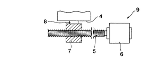
図1は、観察装置の全体を示す正面図、図2は観察装置を図1において右方向から見たときの正面図、図3は観察装置の平面図、図4は照明手段と光学観察手段及び培養容器の関係を示す平面図、図5は照明手段と光学観察手段及び培養容器の関係を示す正面図、図6は光学観察手段で培養容器内の細胞を観察している状態の説明図、図7はワーク戴置台を上下に駆動する装置の説明図、図8はワーク戴置台を水平方向に駆動する装置の説明図、図9は光束をカットした状態の説明図である。
【0012】
上記各図において、符号の1は観察装置であって、この観察装置は、テーブル2上において、図3に示すように、ガイド3に対して軸受3aを介して水平方向にスライド自在に取り付けられたワーク戴置台4と、このワーク戴置台4の側方において、図8に示すように前記ガイド3と平行に配置され、モータ6により正、逆回転自在のX軸ねじ棹5と、このX軸ねじ棹5に装着されたブロックナット7と、このブロックナット7と前記ワーク戴置台4を連結している連棹8から成るX軸アクチエータ9及び前記X軸アクチェエータ9の奥において、図7に示すように垂直方向に配置され、モータ12により正、逆回転自在のZ軸ねじ棹11と、このZ軸ねじ棹11に装着されたブロックナット13と、このブロックナット13に取り付けられたカメラフレーム14と、このカメラフレーム14の上方において、斜め下向きに取り付けられた照明ユニット15と、このカメラフレーム14に対して斜め上向きに取り付けられたレンズ及びCCDカメラ(超小型近接撮影装置)16とから成るZ軸アクチェエータ17を主要構成要素としている。
【0013】
上記構成において、照明ユニット15とレンズ及びCCDカメラ16の光軸aは同軸に設定され、この光軸aの角度はカメラフレーム14の角度を変えることにより、自由に調整することができる。また、照明ユニット15は、その光束15aの径の大きいものが選択されていて、この光束15aは、シャッター装置(図示せず)により、図9に示すように、光束15aの一部を任意にカット15bすることができる。
【0014】
次に、上記構成から成る観察装置1について、その使用例を説明する。
先ず、図1、図2に示すように、セルファクトリー18は右端に寄せたワーク戴置台4上にセットし、観察開始用のキーを操作すると、モータ6が駆動してX軸ねじ棹5が回転し、この回転によりブロックナット7が図1、図3において右から左方向に移動することにより、ワーク戴置台4がガイド3に沿って右から左方向に一緒に移動する。そして、セルファクトリー18が左端の位置まで移動すると、モータ6が停止してワーク戴置台4が止る。この状態において、照明ユニット15とレンズ及びCCDカメラ16の光軸aはセルファクトリー18において、図4に示すように一番端(手前)にある。
【0015】
この状態において、カメラフレーム14を図2に示すように下降させて光軸aを最下段(但し、図5、図6の位置は下から二段目)の培養容器18aに合わせ、更に光軸aの角度を約45°に調整する。この角度は、培養容器18a内の培養液18bの液面上の空間の側壁を経由して直近の上段の培養容器18aの底面18cにレンズ及びCCDカメラ16の焦点が合う角度のため、培養液18bの液面のレベルによっては、45°よりも小さくなったり、大きくなったりする。但し、照明光の屈折率などからは、光軸aは45°が最も好ましい。
カメラフレーム14の角度の調整が終り、観察キーを操作すると、先ず培養容器18aの端に近い位置で観察を行い、この映像はコンピュータの画面又はビデオモニタに映し出され、この映像は記録媒体にとり込まれる。
【0016】
一点の撮影が終ると、モータ6が駆動してZ軸ねじ棹5が回転し、ワーク戴置台4を培養容器18aの巾の1/2移動させて止る。このようにして培養容器18aの1/2(中間)で2度目の観察を終り、更にワーク戴置台4が移動して培養容器18aの端にレンズ及びCCDカメラ16の光軸aを位置させ、ここで3度目の撮影を行う。最下段の培養容器18aについて3ポイントの撮影が終ると、ワーク戴置台4が再び前進して止り、次にX軸アクチェエータ17が駆動して二段目の培養容器18aのところに照明ユニット15とレンズ及びCCDカメラ16をセットし、同じように3ポイントの撮影を行い、これが終ると3段目の培養容器16aへ移り、この繰り返しにより、例えば40段のセルファクトリー18すべてについて、3ポイント撮影の場合、120回の撮影をすべて自動で行う。以上の撮影の制御は、すべて制御回路が行うが、自動制御を切り、マニアルでの撮影も勿論行うこともできるようになっている。
細胞を撮影するとき、この細胞を鮮明に撮影できるようにするため、図9に示すように、照明ユニット15の光束15aの一部をカット15bする。このようにすると、カット15bした側が暗くなり、影がつくので、この影を利用して細胞を立体的、そして鮮明に撮影することができる。
【0017】
【発明の効果】
本発明は以上のように、セルファクトリーで培養中の細胞の様子を、各段すべての培養容器について、光学的な手段で撮影し、観察及び記録することができる。
また、制御回路により撮影はすべて自動化することが可能なため、観察作業に人手と時間がかからない。
また、本発明においては、光束の直径の大きい照明手段を利用したことにより、照明光軸が少しずれても撮影に支障がなく、更に光束の一部をカットすることにより、コントラストのついた、立体的で鮮明な映像を映し出すことができる。
【図面の簡単な説明】
【図1】 本発明に係る観察装置の正面図。
【図2】 本発明に係る観察装置の側面図。
【図3】 本発明に係る観察装置の平面図。
【図4】 照明ユニットとレンズ及びCCDカメラ及びセルファクトリーの関係を示す平面図。
【図5】 照明ユニットとレンズ及びCCDカメラ及びセルファクトリーの関係を示す正面図。
【図6】 レンズ及びCCDカメラで撮影している状態の説明図。
【図7】 Z軸アクチェエータの説明図。
【図8】 X軸アクチェエータの説明図。
【図9】 光束をカットした状態の説明図。
【符号の説明】
1 観察装置
2 テーブル
4 ワーク戴置台
9 X軸アクチェエータ
14 カメラフレーム
15 照明用ユニット
16 レンズ及びCCDカメラ
17 Z軸アクチェエータ
18 セルファクトリー[0001]
BACKGROUND OF THE INVENTION
The present invention relates to an apparatus for directly observing the state of cells being cultured in a culture vessel stacked in multiple stages from the outside by optical means.
[0002]
[Prior art]
As a container for culturing a large amount of cells at once, a cell factory (trade name of Nalgene Nunk International Corporation) is known. This cell factory has a structure in which containers are stacked and fixed in a plurality of stages, and a culture solution is usually stored in a container of each stage up to about a half level. For this reason, even if it is intended to observe the culture state of the cells, the culture state in the uppermost and lowermost containers can be observed from the outside or by optical means, but the culture state in the other containers is Other containers are in the way and cannot be observed.
Therefore, in the past, it was determined that the other stages were the same by observing only the culture state in the uppermost and lowermost containers. However, if possible, it is desired to observe all stages.
[0003]
[Problems to be solved by the invention]
The present invention has been proposed in view of such points, and its object is to provide an apparatus capable of observing cells cultured in a culture container stacked in multiple stages for each stage by optical means. Is to provide.
[0004]
[Means for Solving the Problems]
In order to achieve the above object, in the invention described in
[0005]
Furthermore, in the invention described in
According to the present invention, the observation apparatus can be fully automated.
[0006]
Furthermore, the invention described in
According to the present invention, the state of the cells in the culture vessel can be observed in the best state according to the liquid level.
[0007]
Furthermore, in the invention according to
[0008]
Furthermore, in the invention described in
[0009]
Further, in the invention described in
According to the present invention, the observation apparatus can be fully automated.
[0010]
[Action]
The observation apparatus for cells cultured in the above-described multistage culture container is set by placing the culture containers stacked in multiple stages on the work table of the observation apparatus and moving it between the illumination means and the optical observation means (camera frame) Let For example, when observing cells in the culture vessels at all stages, the illumination means and the optical observation means are matched with the top or bottom culture container, and then the illumination means and the optical observation means are automatically or manually. Is lowered or raised step by step, and images taken for each culture vessel are displayed on a computer screen, a video monitor or the like, and simultaneously recorded (if necessary) on a medium. In each stage of observation, it is also possible to observe at a plurality of points for each stage. At this time, the work placing table is moved in the horizontal direction while changing the points in one stage of the culture vessel.
When observing the inside of a culture vessel at a specific stage, by inputting the identifier of the culture container at this stage to the controller, the driving device automatically identifies the illumination means and the optical observation means by the identifier. Move to and observe.
[0011]
【Example】
1 is a front view showing the entire observation apparatus, FIG. 2 is a front view of the observation apparatus when viewed from the right in FIG. 1, FIG. 3 is a plan view of the observation apparatus, and FIG. 4 is illumination means and optical observation means. FIG. 5 is a front view showing the relationship between the illumination means, the optical observation means, and the culture container. FIG. 6 is an explanatory diagram of a state in which cells in the culture container are observed by the optical observation means. 7 is an explanatory diagram of an apparatus for driving the workpiece mounting table up and down, FIG. 8 is an explanatory diagram of an apparatus for driving the workpiece mounting table in the horizontal direction, and FIG. 9 is an explanatory diagram of a state in which the light beam is cut.
[0012]
In each of the drawings,
[0013]
In the above configuration, the
[0014]
Next, an example of use of the
First, as shown in FIG. 1 and FIG. 2, the
[0015]
In this state, the
When the adjustment of the angle of the
[0016]
When the photographing of one point is completed, the
When the cell is photographed, a part of the
[0017]
【The invention's effect】
As described above, according to the present invention, the state of cells being cultured in a cell factory can be photographed, observed and recorded by optical means for all the culture vessels at each stage.
In addition, since all the photographing can be automated by the control circuit, the observation work does not take time and labor.
Further, in the present invention, by using an illumination means having a large diameter of the light beam, there is no problem in photographing even if the illumination optical axis is slightly deviated, and further, by cutting a part of the light beam, a contrast is obtained. Three-dimensional and clear images can be projected.
[Brief description of the drawings]
FIG. 1 is a front view of an observation apparatus according to the present invention.
FIG. 2 is a side view of an observation apparatus according to the present invention.
FIG. 3 is a plan view of an observation apparatus according to the present invention.
FIG. 4 is a plan view showing a relationship among an illumination unit, a lens, a CCD camera, and a cell factory.
FIG. 5 is a front view showing a relationship among an illumination unit, a lens, a CCD camera, and a cell factory.
FIG. 6 is an explanatory diagram of a state where photographing is performed with a lens and a CCD camera.
FIG. 7 is an explanatory diagram of a Z-axis actuator.
FIG. 8 is an explanatory diagram of an X-axis actuator.
FIG. 9 is an explanatory diagram of a state where a light beam is cut.
[Explanation of symbols]
DESCRIPTION OF
Claims (6)
Priority Applications (1)
| Application Number | Priority Date | Filing Date | Title |
|---|---|---|---|
| JP2003142104A JP4049263B2 (en) | 2003-05-20 | 2003-05-20 | Device for observing cells cultured in a multistage culture vessel |
Applications Claiming Priority (1)
| Application Number | Priority Date | Filing Date | Title |
|---|---|---|---|
| JP2003142104A JP4049263B2 (en) | 2003-05-20 | 2003-05-20 | Device for observing cells cultured in a multistage culture vessel |
Publications (2)
| Publication Number | Publication Date |
|---|---|
| JP2004344016A JP2004344016A (en) | 2004-12-09 |
| JP4049263B2 true JP4049263B2 (en) | 2008-02-20 |
Family
ID=33530291
Family Applications (1)
| Application Number | Title | Priority Date | Filing Date |
|---|---|---|---|
| JP2003142104A Expired - Fee Related JP4049263B2 (en) | 2003-05-20 | 2003-05-20 | Device for observing cells cultured in a multistage culture vessel |
Country Status (1)
| Country | Link |
|---|---|
| JP (1) | JP4049263B2 (en) |
Cited By (2)
| Publication number | Priority date | Publication date | Assignee | Title |
|---|---|---|---|---|
| WO2019230035A1 (en) | 2018-05-30 | 2019-12-05 | 四国計測工業株式会社 | Multi-layer culture vessel observation system, carriage device, and multi-layer culture vessel observation device |
| EP3587553A1 (en) | 2018-06-29 | 2020-01-01 | Shibuya Corporation | Cell observation apparatus |
Families Citing this family (11)
| Publication number | Priority date | Publication date | Assignee | Title |
|---|---|---|---|---|
| JP5101819B2 (en) * | 2006-01-16 | 2012-12-19 | 株式会社カネカ | Cell culture equipment |
| BR112012028786A2 (en) * | 2010-05-11 | 2015-11-24 | Artelis S A | cell culture bioreactor and carrier for a bioreactor |
| JP5713826B2 (en) * | 2011-07-20 | 2015-05-07 | 株式会社アテクト | Culture observation equipment |
| CN102827758A (en) * | 2012-09-24 | 2012-12-19 | 长春理工大学 | Cell microscopic observation monitor in cell factory |
| EP3144379A4 (en) * | 2014-05-14 | 2017-12-27 | Olympus Corporation | Culture observation apparatus |
| JP6732245B2 (en) * | 2016-03-31 | 2020-07-29 | 株式会社ツーセル | Cell culture device |
| CN106919137B (en) * | 2017-04-25 | 2023-08-15 | 李满发 | Automatic control system for cell factory |
| JP7478546B2 (en) * | 2019-03-20 | 2024-05-07 | 四国計測工業株式会社 | Cultivation system, culture device, and multi-layer culture vessel operation device |
| CN110305782B (en) * | 2019-07-15 | 2024-02-20 | 长春理工大学 | Optical axis space posture adjusting device of microscopic monitoring system of cell fermentation tank |
| CN110715606B (en) * | 2019-11-18 | 2021-03-12 | 长春理工大学 | Cell factory bioreactor layer height dynamic calibration method based on region detection |
| CN110747115A (en) * | 2019-11-19 | 2020-02-04 | 长春理工大学 | Cell Factory Bioreactor Microscopic Photoelectric Monitoring System |
Family Cites Families (3)
| Publication number | Priority date | Publication date | Assignee | Title |
|---|---|---|---|---|
| JP2003093041A (en) * | 2001-09-25 | 2003-04-02 | Hamamatsu Photonics Kk | Cultured specimen-observing device |
| JP2003116593A (en) * | 2001-10-17 | 2003-04-22 | Hakuju Inst For Health Science Co Ltd | Method for judging microorganism and device therefor |
| JP4638637B2 (en) * | 2001-11-26 | 2011-02-23 | 廣幸 小川 | Projection detection device |
-
2003
- 2003-05-20 JP JP2003142104A patent/JP4049263B2/en not_active Expired - Fee Related
Cited By (3)
| Publication number | Priority date | Publication date | Assignee | Title |
|---|---|---|---|---|
| WO2019230035A1 (en) | 2018-05-30 | 2019-12-05 | 四国計測工業株式会社 | Multi-layer culture vessel observation system, carriage device, and multi-layer culture vessel observation device |
| KR20210018220A (en) | 2018-05-30 | 2021-02-17 | 시코쿠 케이소쿠 코교 가부시키가이샤 | Multilayer culture vessel observation system, balance device and multilayer culture vessel observation device |
| EP3587553A1 (en) | 2018-06-29 | 2020-01-01 | Shibuya Corporation | Cell observation apparatus |
Also Published As
| Publication number | Publication date |
|---|---|
| JP2004344016A (en) | 2004-12-09 |
Similar Documents
| Publication | Publication Date | Title |
|---|---|---|
| JP4049263B2 (en) | Device for observing cells cultured in a multistage culture vessel | |
| CN108627964B (en) | Full-automatic micro-scanner | |
| US7542202B2 (en) | Microscope and a controlling method thereof | |
| CN106596550B (en) | A kind of tiny insect sample image capturing system | |
| CN1867043A (en) | Digital camera | |
| CN101212568B (en) | Imaging apparatus | |
| CN209745229U (en) | Plant three-dimensional phenotype measuring device | |
| JP2008092882A (en) | Automatic culture equipment | |
| CN1375719A (en) | Inverted microscope system | |
| CN109691083A (en) | Image processing method, image processing apparatus and photographic device | |
| JP6333318B2 (en) | Image processing method, image processing apparatus, and imaging apparatus | |
| CN208477200U (en) | It is a kind of can auto-focusing the micro- scanning system of zoom | |
| CN213239939U (en) | Full-automatic tubercle bacillus scanner equipment | |
| JP2008003331A (en) | Microscope apparatus | |
| CN114166853A (en) | Appearance flaw detection equipment | |
| CN215420508U (en) | Computer image processing device | |
| GB2084754A (en) | Microscope | |
| JP7636824B1 (en) | Method and device for visual inspection of mobile terminals | |
| CN218824959U (en) | Automatic scanning and photographing system for microscope slide | |
| CN110764246A (en) | A device for photographing large-area samples on a microscope and a method of using the same | |
| CN222636376U (en) | Metallographic microscope device | |
| CN110607229A (en) | Cell Metastasis Observation Mechanism and Its Working Method | |
| CN221542005U (en) | High-precision building oblique photography aerial photographing device | |
| CN218006349U (en) | In-cylinder pathology specimen shooting box | |
| US7301861B2 (en) | Coma aberration correcting apparatus for optical pickup |
Legal Events
| Date | Code | Title | Description |
|---|---|---|---|
| A621 | Written request for application examination |
Free format text: JAPANESE INTERMEDIATE CODE: A621 Effective date: 20041102 |
|
| A977 | Report on retrieval |
Free format text: JAPANESE INTERMEDIATE CODE: A971007 Effective date: 20070723 |
|
| A131 | Notification of reasons for refusal |
Free format text: JAPANESE INTERMEDIATE CODE: A131 Effective date: 20070809 |
|
| A521 | Written amendment |
Free format text: JAPANESE INTERMEDIATE CODE: A523 Effective date: 20071002 |
|
| TRDD | Decision of grant or rejection written | ||
| A01 | Written decision to grant a patent or to grant a registration (utility model) |
Free format text: JAPANESE INTERMEDIATE CODE: A01 Effective date: 20071025 |
|
| A61 | First payment of annual fees (during grant procedure) |
Free format text: JAPANESE INTERMEDIATE CODE: A61 Effective date: 20071121 |
|
| R150 | Certificate of patent or registration of utility model |
Free format text: JAPANESE INTERMEDIATE CODE: R150 |
|
| FPAY | Renewal fee payment (event date is renewal date of database) |
Free format text: PAYMENT UNTIL: 20101207 Year of fee payment: 3 |
|
| LAPS | Cancellation because of no payment of annual fees |