JP4029089B2 - Diaphragm for key switch and key switch - Google Patents
Diaphragm for key switch and key switch Download PDFInfo
- Publication number
- JP4029089B2 JP4029089B2 JP2004535950A JP2004535950A JP4029089B2 JP 4029089 B2 JP4029089 B2 JP 4029089B2 JP 2004535950 A JP2004535950 A JP 2004535950A JP 2004535950 A JP2004535950 A JP 2004535950A JP 4029089 B2 JP4029089 B2 JP 4029089B2
- Authority
- JP
- Japan
- Prior art keywords
- key switch
- diaphragm
- leaf spring
- contact
- reference surface
- Prior art date
- Legal status (The legal status is an assumption and is not a legal conclusion. Google has not performed a legal analysis and makes no representation as to the accuracy of the status listed.)
- Expired - Fee Related
Links
- 239000000758 substrate Substances 0.000 claims description 59
- 230000002093 peripheral effect Effects 0.000 claims description 27
- 239000004020 conductor Substances 0.000 claims description 6
- NJPPVKZQTLUDBO-UHFFFAOYSA-N novaluron Chemical compound C1=C(Cl)C(OC(F)(F)C(OC(F)(F)F)F)=CC=C1NC(=O)NC(=O)C1=C(F)C=CC=C1F NJPPVKZQTLUDBO-UHFFFAOYSA-N 0.000 description 30
- 238000010586 diagram Methods 0.000 description 24
- 238000006073 displacement reaction Methods 0.000 description 18
- 239000000428 dust Substances 0.000 description 12
- 239000013039 cover film Substances 0.000 description 9
- 230000000994 depressogenic effect Effects 0.000 description 8
- 238000009429 electrical wiring Methods 0.000 description 8
- 230000000694 effects Effects 0.000 description 5
- 241000628997 Flos Species 0.000 description 4
- 239000011521 glass Substances 0.000 description 4
- 239000000853 adhesive Substances 0.000 description 3
- 230000001070 adhesive effect Effects 0.000 description 3
- 230000007423 decrease Effects 0.000 description 3
- 238000004519 manufacturing process Methods 0.000 description 3
- 230000002159 abnormal effect Effects 0.000 description 2
- 230000007547 defect Effects 0.000 description 2
- 230000006866 deterioration Effects 0.000 description 2
- 230000005489 elastic deformation Effects 0.000 description 2
- 239000002184 metal Substances 0.000 description 2
- 239000011347 resin Substances 0.000 description 2
- 229920005989 resin Polymers 0.000 description 2
- 229920002379 silicone rubber Polymers 0.000 description 2
- 101710083129 50S ribosomal protein L10, chloroplastic Proteins 0.000 description 1
- 101710082414 50S ribosomal protein L12, chloroplastic Proteins 0.000 description 1
- 230000005856 abnormality Effects 0.000 description 1
- 238000013459 approach Methods 0.000 description 1
- 230000001413 cellular effect Effects 0.000 description 1
- 239000000835 fiber Substances 0.000 description 1
- 230000001771 impaired effect Effects 0.000 description 1
- 238000009434 installation Methods 0.000 description 1
- 230000002452 interceptive effect Effects 0.000 description 1
- 108010028930 invariant chain Proteins 0.000 description 1
- 238000005259 measurement Methods 0.000 description 1
- 230000000149 penetrating effect Effects 0.000 description 1
- 239000004033 plastic Substances 0.000 description 1
- 239000000126 substance Substances 0.000 description 1
Images


Classifications
-
- H—ELECTRICITY
- H01—ELECTRIC ELEMENTS
- H01H—ELECTRIC SWITCHES; RELAYS; SELECTORS; EMERGENCY PROTECTIVE DEVICES
- H01H13/00—Switches having rectilinearly-movable operating part or parts adapted for pushing or pulling in one direction only, e.g. push-button switch
- H01H13/70—Switches having rectilinearly-movable operating part or parts adapted for pushing or pulling in one direction only, e.g. push-button switch having a plurality of operating members associated with different sets of contacts, e.g. keyboard
- H01H13/702—Switches having rectilinearly-movable operating part or parts adapted for pushing or pulling in one direction only, e.g. push-button switch having a plurality of operating members associated with different sets of contacts, e.g. keyboard with contacts carried by or formed from layers in a multilayer structure, e.g. membrane switches
-
- H—ELECTRICITY
- H01—ELECTRIC ELEMENTS
- H01H—ELECTRIC SWITCHES; RELAYS; SELECTORS; EMERGENCY PROTECTIVE DEVICES
- H01H13/00—Switches having rectilinearly-movable operating part or parts adapted for pushing or pulling in one direction only, e.g. push-button switch
- H01H13/02—Details
- H01H13/26—Snap-action arrangements depending upon deformation of elastic members
- H01H13/48—Snap-action arrangements depending upon deformation of elastic members using buckling of disc springs
-
- H—ELECTRICITY
- H01—ELECTRIC ELEMENTS
- H01H—ELECTRIC SWITCHES; RELAYS; SELECTORS; EMERGENCY PROTECTIVE DEVICES
- H01H2203/00—Form of contacts
- H01H2203/036—Form of contacts to solve particular problems
- H01H2203/054—Form of contacts to solve particular problems for redundancy, e.g. several contact pairs in parallel
-
- H—ELECTRICITY
- H01—ELECTRIC ELEMENTS
- H01H—ELECTRIC SWITCHES; RELAYS; SELECTORS; EMERGENCY PROTECTIVE DEVICES
- H01H2205/00—Movable contacts
- H01H2205/016—Separate bridge contact
- H01H2205/018—Support points upwardly concave
-
- H—ELECTRICITY
- H01—ELECTRIC ELEMENTS
- H01H—ELECTRIC SWITCHES; RELAYS; SELECTORS; EMERGENCY PROTECTIVE DEVICES
- H01H2215/00—Tactile feedback
- H01H2215/034—Separate snap action
- H01H2215/036—Metallic disc
Landscapes
- Push-Button Switches (AREA)
Description
本発明は、円錐状の台座部とこの上部に球面上のドーム状部を備えたキースイッチ(平面スイッチ)用のダイヤフラム、キースイッチに関する。 The present invention relates to a diaphragm and a key switch for a key switch (planar switch) having a conical pedestal portion and a spherical dome-shaped portion on the top.
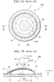
図1は、第1の従来のキースイッチ100の概略構成を示す図であり、図1Aは、キースイッチ100の平面図であり、図1Bは、図1AにおけるIB−IB断面を示す図である。図2は、キースイッチ100を押した状態を示す図である。たとえば携帯電話の押しボタンに使用されている従来のキースイッチ100は、環状の配線パターン2と配線パターン2のほぼ中央部に配置され配線パターン2とは離反している配線パターン4とが設けられている基板6と、中央部が基板6から離反する方向に湾曲し、基板6に載置されているキースイッチ用ダイヤフラム102と、キースイッチ用ダイヤフラム102と基板6とを覆っているカバーフィルム10とによって構成されている。なお、キースイッチ100を携帯電話等の機器に使用する場合、一般的に、100万回以上の押し下げに耐える耐久力が要求される。
また、基板6とキースイッチ用ダイヤフラム102とに接触しているカバーフィルム10の片側の面(基板6側の面)は粘着性を備えるので、キースイッチ用ダイヤフラム102が、基板6の表面に沿う方向にずれない。
キースイッチ用ダイヤフラム102の周縁部は接点12を形成し、キースイッチ用ダイヤフラム102が基板6上に載置された状態では、接点12と基板6上に形成された配線パターン2とが互いに電気的に接触する。
図2に示すように、キースイッチ用ダイヤフラム102の中央部を、基板6の方向に押すと、キースイッチ用ダイヤフラム102の中央部が基板6の方向にへこみ、中央部の凹側に設けられているキースイッチ用ダイヤフラム102の接点104と基板6に形成された配線パターン4とが互いに電気的に接続して、配線パターン2と配線パターン4とが互いに電気的に接続される。
ここで、キースイッチ用ダイヤフラム102は、可撓性と導電性とを具備する、たとえば金属性の薄板を加工して形成され、また、キースイッチ用ダイヤフラム102は、適宜の高さを具備する円錐台形状の台座部(ペデスタル;pedestal)16の上部側(台座部の窄まった側)に、この上部側に突出した球面状のドーム状部18を備える。
そして、キースイッチ100を押した場合、キースイッチ用ダイヤフラム102の台座部16はほとんど変形せず、接点104と基板6の配線パターン4とが互いに電気的に接触するまで、ドーム状部18が主に弾性変形する。したがって、台座部16が存在しない場合よりも、大きな押し下げストロークと大きな押し下げ力とを確保することができ、これによって良好なクリック感を得ることができる。
なお、キースイッチ100を、図2に示すように基板6の方向に押し下げ、またはこの押し下げを解除するときに、基板6とキースイッチ用ダイヤフラム102とで囲繞されている空間の体積が変化して、この空間の空気圧の変化を防止するために、キースイッチ用ダイヤフラム102の周縁近傍においてカバーフィルム10に貫通孔20が設けられている。そして、貫通孔20を空気が通過することにより、押し下げまたは押し下げ解除したときにおける空間内の空気圧をほぼ一定に保っている。FIG. 1 is a diagram showing a schematic configuration of a first
Further, since one surface (the surface on the
The peripheral portion of the
As shown in FIG. 2, when the central portion of the
Here, the
When the
When the
しかし、キースイッチ用ダイヤフラム102と基板6とで囲繞された空間に、たとえばガラスフロスなどの粉塵が侵入した場合、このガラスフロスによって、キースイッチ100を押し下げても、基板6の配線パターン4とキースイッチ用ダイヤフラム102の接点104とが互いに接触できず、キースイッチ100の接触不良によるスイッチング機能障害が発生する場合があるという問題がある。
そこで、上記問題を回避するために、図3(A)、図3(B)に示すように、中央部に突起102Bを備えたキースイッチ用ダイヤフラム102Aやキースイッチ用ダイヤフラム102Cを用いて、キースイッチ200やキースイッチ300のようなキースイッチを構成することが考えられる。
図3(A)は、第2の従来のキースイッチ200の断面を示す図である。キースイッチ200のキースイッチ用ダイヤフラム102Aは、ほぼ中央部に、凹側に突出している突起102Bを具備している。キースイッチ200を押し下げた場合、接点104Aと基板6の配線パターン4とが互いに接触し電気的に接続する。
図3(B)は、第3の従来のキースイッチ300の断面を示す図である。キースイッチ300のキースイッチ用ダイヤフラム102Cは、ほぼ中央部に、凹側に突出している突起102Bを複数(本例では3つ)具備している。キースイッチ300を押し下げた場合、各接点104Aのうちの少なくとも1つと基板6の配線パターン4とが互いに接触し電気的に接続する。
キースイッチ200ではこれを押し下げた場合、基板6の配線パターン4と接触する接点104Aの面積が、キースイッチ100の接点104よりも小さいので、囲繞された空間にガラスフロス等の粉塵が侵入しても、キースイッチ200の接触不良は、キースイッチ100よりも発生しにくい。
また、キースイッチ300では、接点104Aを複数備えており、キースイッチ300を押し下げた場合、各接点104Aのうちの少なくとも1つの接点が、基板6の配線パターン4と接触すれば、キースイッチの接触不良を回避できるので、キースイッチ200よりも、一層接触不良が発生しにくい。
ところが、上記囲繞された空間に侵入した粉塵がガラスフロスやその他の繊維である場合には、突起102Bによって、粉塵が押しのけられるので、キースイッチ200やキースイッチ300を押し下げた場合の接触不良が回避されやすいが、粉塵がたとえば接着剤飛沫や樹脂飛沫などのような付着しやすい物質で構成され、キースイッチ用ダイヤフラム102A、102Cの接点104Aに付着している場合には、接触不良が発生しやすいという問題がある。
さらに、キースイッチ200のキースイッチ用ダイヤフラム102Aやキースイッチ300のキースイッチ用ダイヤフラム102Cでは、このほぼ中央部(押し下げられる部分)の凹側(基板6側;台座部16側)に、突起102Bが形成されているので、突起102Bの先端側に形成されている接点104Aと、基板6の配線パターン4との間の距離が、非操作時(キースイッチ200、キースイッチ300が、図3(A)や図3(B)に示すように押し下げられていない状態)において、キースイッチ100よりも小さくなる。したがって、キースイッチ200やキースイッチ300では、押し下げのストロークがキースイッチ100よりも小さくなり、良好なクリック感が失われるおそれがある。
そこで、上記押し下げのストロークを確保するために、台座部16の高さを高くすることが考えられる。しかし、台座部16の高さが高くなるように、キースイッチ200のキースイッチ用ダイヤフラム102Aやキースイッチ300のキースイッチ用ダイヤフラム102Cを、たとえばプレスによって成型すると、キースイッチ用ダイヤフラム102Aやキースイッチ用ダイヤフラム102Cが、特に台座部16のところで、大きく塑性変形しなければならず、この大きな塑性変形により、各キースイッチ用ダイヤフラム102A、102Cに大きな残留応力が発生する。そして、これらのキースイッチ200やキースイッチ300を押し下げ、この押し下げを解除する動作を繰り返す度に、キースイッチ用ダイヤフラム102Aやキースイッチ用ダイヤフラム102Cが弾性変形し、この弾性変形による繰り返し応力が上記残留応力に加えられて大きな応力が発生し、キースイッチ用ダイヤフラム102Aやキースイッチ用ダイヤフラム102Cが疲労破壊しやすくなり、耐久性が悪化するという問題がある。
また、キースイッチ300の場合には、キースイッチ用ダイヤフラム102Cが突起102Bを複数備えているので、キースイッチ200よりも接触不良が発生しにくいが、キースイッチ300を押し下げたときに、キースイッチ用ダイヤフラム102Cの各接点104Aのうち1つの接点が、基板6の配線パターン4に接触すると、上記1つの接点は、キースイッチ用ダイヤフラム102Cに対して偏心しているので、キースイッチ用ダイヤフラム102Cに偏在した応力が発生し、耐久性がキースイッチ200よりもさらに悪化する場合がある。
図3(C)は、第4の従来のキースイッチ400の断面図である。キースイッチ400のキースイッチ用ダイヤフラム102Dは、ほぼ中央部に、突起102Bの代わりに貫通孔102Eが設けられている。
キースイッチ400を押し下げた場合、貫通孔102Eの外周縁の基板6側のエッジ部が接点104Bを形成し、この接点104Bが基板6の配線パターン4とが互いに接触し電気的に接続する。キースイッチ400では、キースイッチ用ダイヤフラム102Dのほぼ中央部の貫通孔102Eのエッジが接点104Bを形成しているので、キースイッチ400を押し下げた場合、上記囲繞された空間に粉塵が存在しても、接点104Bが基板6の配線パターン4に接触しやすく、接触不良を回避することができる。また、キースイッチ用ダイヤフラム102Dの凹側に突起が存在しないため、台座部16の高さを高くしなくても、押し下げストロークを確保することができ、良好なクリック感を得ることができる。
しかし、キースイッチ400を押し下げたときに、キースイッチ用ダイヤフラム102Dが弾性変形し、貫通孔102Eの外周縁に応力集中が発生し、貫通孔102E外周縁からキースイッチ用ダイヤフラム102Dの外周に向かってクラックが発生する場合があり、キースイッチ400の耐久性が悪化する場合があるという問題がある。
また、キースイッチ400を押し下げたときに、貫通孔102Eが存在するために、カバーフィルム10の粘着部が基板6の配線パターン4に転写され、これによって、キースイッチ400の接触不良が発生する場合があるという問題がある。
なお、貫通孔102Eに対応する部分において、粘着性が無いカバーフィルムを使用することが考えられるが、このようなカバーフィルムを製作することは煩雑であり、また、上記粘着性が無い部分と貫通孔102Eとの位置を合致させて、キースイッチを組み立てることは困難である。
さらに、また、キースイッチ用ダイヤフラム102を用いて構成されたキースイッチ100は、図1Bに示すように、キースイッチ用ダイヤフラム102を押圧するための押圧部材(アクチュエータ)AC1を備え、このアクチュエータAC1は、たとえば、キースイッチ100のおもて面に配置される図示しないシート状の弾性支持部材(たとえばシリコンラバーシート)と一体化して形成され、シリコンラバーシートと共に、キースイッチの基板6とキースイッチ用ダイヤフラム102とに積層されて、キースイッチ100に設置されのであるが、この設置のときに、キースイッチ用ダイヤフラム102の中心CL10に対して、アクチュエータAC1の中心CL12がΔL3だけずれて設置される場合がある。
このようにアクチュエータAC1がずれて設置されると、従来のキースイッチ用ダイヤフラム102を用いたキースイッチ100では、上記ずれ量にほぼ比例して、後に詳しく説明するクリック率(クリック感の良否を数値で客観的に示すための指標の1つ)が低下する。すなわち、ずれ量によって良好なクリック感が損なわれるという問題がある。なお、アクチュエータのずれによって発生する上記問題は、他の各キースイッチ200、300、400においても発生する問題である。
本発明は、上記問題点に鑑みてなされたものであり、本発明によれば、押した場合に良好なクリック感を得ることができると共に、接触不良の発生を回避でき、耐久性が高いキースイッチ用ダイヤフラム、キースイッチを提供することができる。
本発明の第1の技術的側面によれば、キースイッチ用ダイヤフラムは、導電性を有する第1の板バネ部であって、前記第1の板バネ部が基準面に対して位置固定される基部と前記基準面から離れる凸形状を有する板部とを備えるものと、導電性を有し、前記板部の中央部に前記基準面から離れる方向に突出して形成される第2の板バネ部とを具備し、前記第2の板バネ部に前記基準面に向かう方向の外力が付加されると、少なくとも前記中央部の周縁部が前記基準面に接触することを特徴とする。
本発明の第2の技術的側面によれば、キースイッチ用ダイヤフラムは、さらに、前記第2の板バネ部に前記基準面に向かって突出形成される少なくとも1つの突出部を具備し、前記第2の板バネ部に前記基準面に向かう方向の外力が付加されると、少なくとも前記突出部が前記基準面に接触することを特徴とする。
本発明の第3の技術的側面によれば、キースイッチ用ダイヤフラムは、第1の技術的側面に加えて、さらに、前記第2の板バネ部に前記基準面から離れる方向に突出して形成され、導電性を有する第3の板バネ部を具備し、前記第3板バネ部に前記基準面に向かう方向の外力が付加されると、少なくとも前記第3の板バネ部の周縁部が前記基準面に接触することを特徴とする。
本発明の第4の技術的側面によれば、キースイッチ用ダイヤフラムは、第1の技術的側面に加えて、さらに、前記第2の板バネ部に形成される開口部を具備し、前記第2の板バネ部に前記基準面に向かう方向の外力が付加されると、少なくとも前記開口部の周縁部が前記基準面に接触することを特徴とする。
本発明の第5の技術的側面によれば、キースイッチ用ダイヤフラムは、第2の技術的側面に加えて、前記突出部は3個の突起部を有し、各前記突起部は前記第2の板バネ部の中心部に中心をもつ円の円周上で等間隔に配置されることを特徴とする。However, if dust such as glass floss enters the space surrounded by the
In order to avoid the above problem, as shown in FIGS. 3 (A) and 3 (B), a
FIG. 3A is a view showing a cross section of a second
FIG. 3B is a diagram showing a cross section of a third
When the
The
However, when the dust that has entered the enclosed space is glass floss or other fibers, the dust is pushed away by the
Further, in the
In view of this, it is conceivable to increase the height of the
In the case of the
FIG. 3C is a cross-sectional view of a fourth
When the
However, when the
Further, when the
In addition, although it is possible to use a cover film without adhesiveness in the part corresponding to the through-
Furthermore, as shown in FIG. 1B, the
When the actuator AC1 is displaced as described above, in the
The present invention has been made in view of the above problems, and according to the present invention, it is possible to obtain a good click feeling when pressed and to avoid the occurrence of poor contact and to achieve a high durability key. A diaphragm for a switch and a key switch can be provided.
According to the first technical aspect of the present invention, the key switch diaphragm is a first leaf spring portion having conductivity, and the position of the first leaf spring portion is fixed with respect to a reference plane. A second plate spring portion having a base portion and a plate portion having a convex shape separating from the reference surface, and having conductivity and projecting in a direction away from the reference surface at a central portion of the plate portion; When an external force in a direction toward the reference plane is applied to the second leaf spring portion, at least a peripheral portion of the central portion contacts the reference plane.
According to a second technical aspect of the present invention, the key switch diaphragm further includes at least one protrusion formed on the second leaf spring portion so as to protrude toward the reference surface. When an external force in a direction toward the reference surface is applied to the second leaf spring portion, at least the protrusion comes into contact with the reference surface.
According to the third technical aspect of the present invention, in addition to the first technical aspect, the key switch diaphragm is formed to protrude from the second leaf spring portion in a direction away from the reference surface. And a third leaf spring portion having conductivity, and when an external force in a direction toward the reference plane is applied to the third leaf spring portion, at least a peripheral portion of the third leaf spring portion is the reference portion. It is characterized by contacting the surface.
According to a fourth technical aspect of the present invention, the key switch diaphragm further includes an opening formed in the second leaf spring portion in addition to the first technical aspect, When an external force in a direction toward the reference surface is applied to the second leaf spring portion, at least a peripheral edge portion of the opening is in contact with the reference surface.
According to a fifth technical aspect of the present invention, in addition to the second technical aspect, the key switch diaphragm has three protrusions, and each of the protrusions is the second It is characterized by being arranged at equal intervals on the circumference of a circle having a center at the center of the leaf spring part.
図1Aは、第1の従来のキースイッチの概略構成を示す図、図1Bは図1AのIB−IBに沿った断面図である。
図2は、第1の従来キースイッチを押した状態を示す図である。
図3(A)は第2の従来のキースイッチの概略構成を示す図、図3(B)は第3の従来のキースイッチの概略構成を示す図、図3(C)は、第4の従来のキースイッチの概略構成を示す図である。
図4Aは、本発明の第1の実施の形態に係るキースイッチを構成するキースイッチ用ダイヤフラムの概略構成を示す図、図4Bは図4AのIVB−IVBに沿った断面図である。
図5(A)はキースイッチ用ダイヤフラムによって構成されたキースイッチを押し下げた状態を示す図、図5(B)は図5(A)のキースイッチを押し下げたときの接触面パターンを示す図である。
図6(A)は本発明の第2の実施の形態に係るキースイッチを構成するキースイッチ用ダイヤフラムの概略構成を示す図、図6(B)は図6(B)のキースイッチを押し下げたときの接触面パターンを示す図である。
図7(A)は、本発明の第3の実施の形態に係るキースイッチを構成するキースイッチ用ダイヤフラムの概略構成を示す図、図7(B)は図7(A)のキースイッチを押し下げたときの接触面パターンを示す図である。
図8Aは、本発明の第4の実施の形態に係るキースイッチを構成するキースイッチ用ダイヤフラムの概略構成を示す図、図8Bは図8AのVIIIB−VIIIBに沿った断面図である。
図9は、クリック率を説明する図である。
図10は、アクチュエータ変位量とキースイッチ用ダイヤフラムのクリック率の関係およびアクチュエータ変位量とキースイッチ用ダイヤフラムの変位荷重値との関係を示す図である。1A is a diagram showing a schematic configuration of a first conventional key switch, and FIG. 1B is a cross-sectional view taken along the line IB-IB in FIG. 1A.
FIG. 2 is a diagram illustrating a state in which the first conventional key switch is pressed.
3A is a diagram showing a schematic configuration of a second conventional key switch, FIG. 3B is a diagram showing a schematic configuration of a third conventional key switch, and FIG. It is a figure which shows schematic structure of the conventional key switch.
4A is a diagram showing a schematic configuration of a key switch diaphragm constituting the key switch according to the first embodiment of the present invention, and FIG. 4B is a cross-sectional view taken along IVB-IVB in FIG. 4A.
FIG. 5A is a diagram showing a state in which a key switch constituted by a key switch diaphragm is depressed, and FIG. 5B is a diagram showing a contact surface pattern when the key switch in FIG. 5A is depressed. is there.
FIG. 6A is a diagram showing a schematic configuration of a key switch diaphragm constituting the key switch according to the second embodiment of the present invention, and FIG. 6B is a diagram in which the key switch of FIG. 6B is pushed down. It is a figure which shows the contact surface pattern at the time.
FIG. 7A is a diagram showing a schematic configuration of a key switch diaphragm constituting a key switch according to a third embodiment of the present invention, and FIG. 7B is a diagram showing that the key switch of FIG. 7A is depressed. It is a figure which shows the contact surface pattern at the time.
FIG. 8A is a diagram showing a schematic configuration of a key switch diaphragm constituting a key switch according to a fourth embodiment of the present invention, and FIG. 8B is a sectional view taken along line VIIIB-VIIIB in FIG. 8A.
FIG. 9 is a diagram illustrating the click rate.
FIG. 10 is a diagram showing the relationship between the actuator displacement amount and the click rate of the key switch diaphragm and the relationship between the actuator displacement amount and the displacement load value of the key switch diaphragm.
第1実施形態
図4は、本発明の第1の実施の形態に係るキースイッチ1を構成するキースイッチ用ダイヤフラム30の概略構成を示す図である。図4Aは、キースイッチ用ダイヤフラム30の平面図であり、図4Bは、図4AのIVB−IVB断面を示す図である。図5は、キースイッチ用ダイヤフラム30によって構成されたキースイッチ1を押し下げた状態を示す図である。なお、図4Aにおいては、理解を容易にするために基板6やカバーフィルム10や基板6の配線パターン2、4の表示を省略してある。
キースイッチ用ダイヤフラム30は、可撓性と導電性とを具備する薄板(たとえば金属の薄い板)を、たとえばプレス加工することによって一体的に形成されている。キースイッチ用ダイヤフラム30は、球面状のドーム状部18のほぼ中央部に、絞り上げて形成されることによって、ドーム状部18の上側(凸側)に突出した外方突出部32を備えている。すなわち、キースイッチ用ダイヤフラム30は、円錐台形状の台座部16の上部側に、導体パターン2によって画成される基準面PLから離れる方向(Z軸負方向)に突出した球面状のドーム状部18を備えると共に、このドーム状部18のほぼ中央部に、ドーム状部18の内面側(凹側)周縁部を接点34として、ドーム状部18の外面側(凸側)に基準面PLから離れる方向に突出した外方突出部32を備えている。
換言すれば、キースイッチ用ダイヤフラム30は、可撓性と導電性とを具備する薄板よりなり、円錐台形状の台座部16とこの台座部の上部側(窄まった側)でこの上部側に突出した球面状のドーム状部18とを備えていると共に、ドーム状部18の外面側(凸面側;台座部側とは反対側)に突出した円形状の外方突出部32をドーム状部18のほぼ中央部に備え、外方突出部32の内面側(台座部16側;ドーム状部18の凹面側)の周縁部(外方突出部32とドーム状部18との境界部)が接点34を形成している。
さらに、外方突出部32は、筒状の円錐台形状の台座部32Aの上部側(台座部32Aの窄まった側)に、この上部側に突出した球面状のドーム状部32Bを備えると共に、このドーム状部32Bのほぼ中央部に、ドーム状部32Bの内面側(凹側)に突出し、先端部が接点38を構成している突起(内方突出部)36を備えている。
換言すれば、外方突出部32のほぼ中央部には、外方突出部32の内面側(台座部16側;ドーム状部18の凹面側)に突出して接点38を構成する突起36が設けられている。
次に、キースイッチ1にZ軸正方向の外力を付与した場合について、図5を用いて説明する。正方向とは基板6あるいは基準面PLに接近する向きを意味する。キースイッチ1のほぼ中央部を、基板6方向に押すと、キースイッチ用ダイヤフラム30は弾性変形し(キースイッチ用ダイヤフラム30のドーム状部18とドーム状部32Bとが主に弾性変形し)、キースイッチ用ダイヤフラム30の接点34や接点38が基板6の配線パターン4に接触する。なお、接触した部分は、図5(B)に示すように、環状の接触面C21と、この接触面の内側ほぼ中央部に形成された円形上の接触面C22とによって形成される。
ドーム状部18と台座部16は2つの状態、すなわち図4Aの安定状態および外力(Z軸正方向)の付与により安定化する図5(A)の準安定状態とを有するトグル機構を備えた第1の板バネ部として機能する。また上方突出部32は第2の板バネ部として機能する。周縁部34は2つの板バネを連結する連結部として機能する。したがって、本実施例のキースイッチ用ダイヤフラム30は、基部16および板部18を備える第1の板バネ部18、16、板部18に連結部34を介して連結される第2の板バネ部32を備えるものである。板部18の外縁部17は基部16によって基準面PLに対して位置固定される。
なお、本発明によるキースイッチ用ダイヤフラムは、第1の板バネ部や第2の板バネ部が図4Aに示すように同心円状の皿バネに限定されるものではなく楕円形状の皿バネであってもよく、その一断面が図4B、図5(A)で示されるような板バネであればよい。すなわち、本発明は板部18の両端部(外縁部)17,17が基部16,16によって基準面PLに対して位置固定され、第2の板バネ部32が周縁部34,34によって第1の板バネ部18,18に固定されるような断面を有するダイヤフラムに対して適用される。たとえば、リボン状の板バネから構成されるダイヤフラムの場合には周縁部34の接触パターンC21は環状ではなく接触パターンC22に対して実質的に対称な2つの位置に離れて存在する。
なお、キースイッチ1を押していない状態では、キースイッチ用ダイヤフラム30の接点38は接点34よりも同レベルか僅かに高い位置、すなわち、基準位置PLとの距離が接点34と実質的に同一か基準位置PLに対して接点34より僅かに離れた位置に設けられている。したがって、キースイッチ1を押したときに、第1の板バネであるドーム状部18と第2の板バネであるドーム状部32Bとがそれぞれ適宜弾性変形し、接点34と接点38とが、ともに配線パターン4に(たとえばほぼ同時に)接触する。これにより、キースイッチ1を押した場合のクリック感が、押し下げ途中で急激に変化する事態を回避することができる。
また、接点と配線パターン同士の接触により、キースイッチ用ダイヤフラム30を介して、基板6の配線パターン2と配線パターン4とが互いに電気的に接続される。キースイッチ用ダイヤフラム30に対する配線パターン4方向(Z軸正方向)への外力の付加がなくなると、図5(A)の状態が不安定となって押圧状態が解除されて、キースイッチ用ダイヤフラム30が弾性変形をする前の初期形状(安定状態)に戻る。その結果、キースイッチ用ダイヤフラム30の接点34や接点38が基板6の配線パターン4から離反し、基板6の配線パターン2と配線パターン4との間の電気的接続が遮断される。
キースイッチ用ダイヤフラム30で構成されたキースイッチ1によれば、ドーム状部18と上方突出部32とを連結する周縁部が接点38を囲むリング状の接点34を構成するので、キースイッチ1を押した場合にエッジ状の接点34が配線パターン4に接触する。その結果、キースイッチ用ダイヤフラム30と基板6とで囲繞されている空間内に粉塵が侵入したり、接点34の一部に接着剤飛沫や樹脂飛沫などが付着していても、接点34と配線パターン4との接触を確保することができる。したがって、キースイッチ1を押した場合の接触不良の発生を回避することができる。
なお、外方突出部32の外径は、ダイヤフラム30の外径の20%以上かつ2.5mm以下とすることが好ましい。このような構成とすることでエッジ34が電気的接点として機能し、かつ外方突出部32の周縁部周辺における応力分散が効率よく行われて耐久性も向上する。
さらに、接点34と共に、接点38も配線パターン4に接触するので、キースイッチ1を押した場合の接触不良の発生を一層回避することができると共に、キースイッチ1を押した場合、外方突出部32のほぼ中央部に設けられている突起36が配線パターン4に接触すると、第2の板バネとしての外方突出部32の球面状のドーム状部32Bがそれ以上変形しない。その結果、ドーム状部32Bが不必要な応力を受けることを防止することができ、キースイッチ用ダイヤフラム30の耐久性を向上させることができる。
また、キースイッチ用ダイヤフラム30のドーム状部18のほぼ中央部に設けられている外方突出部32が、ドーム状部18の外側、すなわちドーム状部18に対して配線パターン4から離隔する方向(Z軸負方向)に突出している。したがって、台座部16の高さを高くしなくても、キースイッチ1を押し下げたときのストロークを、従来のキースイッチ100と同様に大きく確保することができ、良好なクリック感を確保することができると共に、台座部16の高さを高くする必要がないので、キースイッチ用ダイヤフラム30をプレス成形する場合、キースイッチ用ダイヤフラム30に発生する残留応力を低く押えることができ、キースイッチ用ダイヤフラム30の耐久力を向上させることができる。
また、キースイッチ1を押した場合には、図5(B)に示すようにキースイッチ用ダイヤフラム30のほぼ中央部が2次元的に基板6の配線パターン4に接触する。したがって、キースイッチ用ダイヤフラム30に、偏心した応力が発生しないので、キースイッチ用ダイヤフラム30に発生する応力を均一に配分することができ、キースイッチ用ダイヤフラム30の押し下げ、押し下げ解除を繰り返した場合の耐久性を向上させることができる。
さらに、キースイッチ1は従来のキースイッチ400との対比で中央部に貫通孔が設けられた第1の板バネであるドーム状部18のほかに第2の板バネである突出部32および周縁部34を備える。したがって、孔の周縁に発生する応力集中が発生しないのでキースイッチ1の耐久性が向上する。なお、キースイッチ用ダイヤフラム30において、ドーム状部32Bのほぼ中央部に設けられている突起36を削除してもよい。
突出部32がドーム状部18に対して配線パターン4から離隔する方向(Z軸負方向)に突出しているので、この部分でカバーフィルム10が弾性変形して張力が増して突出部32への圧力も増大するので、カバーフィルム10のキースイッチ1を接着保持する力を大きくすることができる。
第2実施形態
図6は、本発明の第2の実施形態に係るキースイッチを構成するキースイッチ用ダイヤフラム40の概略構成を示す図である。キースイッチ用ダイヤフラム40は、外方突出部32のドーム状部32Bのほぼ中央部に第1の実施形態の突起36の代わりに、外方突出部32のドーム状部32Bのほぼ中央部に外方突出部42を設けたものであり、その他の点は、キースイッチ用ダイヤフラム30とほぼ同様に構成されている。
すなわち、キースイッチ用ダイヤフラム40は、外方突出部32のドーム状部32Bのほぼ中央部に、ドーム状部32Bの内面側(凹側)周縁部を接点44とする外方突出部42であって、ドーム状部32Bの外面側(凸側)に基準面PLから離れるように突出した外方突出部42を備えている。なお、外方突出部42は、筒状の円錐台形状の台座部42Aの上部側(台座部42Aの窄まった側)に、この上部側に突出した球面状のドーム状部42Bを備えている。したがって、外方突出部42は第2の板バネ部としての上方突出部32に形成された第3の板バネ部として機能する。
換言すれば、外方突出部32のほぼ中央部には、外方突出部32の外面側(台座部16側とは反対側)に突出して、外方突出部32の内面側(台座部16側)の周縁部(外方突出部32との境界部)を環状の接点44とする外方突出部42が設けられている。
キースイッチ用ダイヤフラム40によって構成されているキースイッチのほぼ中央部を押すと、キースイッチ用ダイヤフラム40が弾性変形し、キースイッチ用ダイヤフラム40の接点34や接点44が基板6の配線パターン4に接触する。なお、接触した部分は、図6(B)に示すように、環状の接触面C31と、この接触面の内側ほぼ中央部に形成された環状の接触面C32とによって形成される。接触により、キースイッチ用ダイヤフラム40を介して、基板6の配線パターン2と配線パターン4とが互いに電気的に接続される。
キースイッチ用ダイヤフラム40によって構成されているキースイッチによれば、第1の実施形態に係るキースイッチ1とほぼ同様に動作しほぼ同様の効果を奏する。なお、キースイッチ1とは異なり、接点44がエッジ状に形成されているので、基板6とキースイッチ用ダイヤフラム40とで囲繞されている空間内に粉塵が侵入した場合でも、接点34の他に接点44も配線パターン4に接触しやすくなり、キースイッチを押した場合の接触不良を一層回避することができる。
第3実施形態
図7は、本発明の第3の実施形態に係るキースイッチを構成するキースイッチ用ダイヤフラム50の概略構成を示す図である。キースイッチ用ダイヤフラム50は、外方突出部32のドーム状部32Bのほぼ中央部に、突起36の代わりに貫通孔52を設けた点が、第1の実施の形態に係るキースイッチ用ダイヤフラム30とは異なり、その他の点は、キースイッチ用ダイヤフラム30とほぼ同様に構成されている。換言すれば、外方突出部32のほぼ中央部には貫通孔52を備えてあって、この貫通孔52の内面側(台座部16側)の周縁部に接点58が形成されている。
キースイッチ用ダイヤフラム50によって構成されているキースイッチのほぼ中央部を押すと、キースイッチ用ダイヤフラム50が弾性変形し、キースイッチ用ダイヤフラム50の接点34や、貫通孔52の内面側(ドーム状部32Bの凹面側)の周縁部で形成された接点58が基板6の配線パターン4に接触する。なお、接触した部分は、図7(B)に示すように、環状の接触面C41と、この接触面の内側ほぼ中央部に形成された環状の接触面C42とによって形成される。
キースイッチ用ダイヤフラム50によって構成されているキースイッチのよれば、第1の実施形態に係るキースイッチ1とほぼ同様に動作しほぼ同様の効果を奏する。なお、キースイッチ1とは異なり、接点58がエッジ状に形成されているので、基板6とキースイッチ用ダイヤフラム50とで囲繞されている空間内に粉塵が侵入している場合でも、接点34の他に接点58も配線パターン4に接触しやすくなり、キースイッチを押した場合の接触不良を一層回避することができる。
また、キースイッチ用ダイヤフラム30やキースイッチ用ダイヤフラム50を使用したキースイッチによれば、外方突出部32のドーム状部32Bの外方側(基板6と離反する側)に突出物がないので、キースイッチ用ダイヤフラム30やキースイッチ用ダイヤフラム50の高さが、キースイッチ用ダイヤフラム40よりも低くなり、キースイッチの高さを押えることによってキースイッチを小型化することができる。
さらに、キースイッチ50は従来のキースイッチ400との対比で中央部に貫通孔が設けられている点で共通しているが、キースイッチ50の貫通孔(開口部)52は第1の板バネ18とは独立したバネ要素である第2の板バネ32上に形成されている。したがって、キースイッチ50の接触パターンは図7(B)に示すように2つの環状パターンC41、C42で構成され、応力が適切に分散される。したがつて、開口部52の周縁に発生する応力集中が発生しないのでキースイッチ1の耐久性が向上する。
第4実施形態
図8は、本発明の第4の実施形態に係るキースイッチを構成するキースイッチ用ダイヤフラム60の概略構成を示す図である。なお、図8Aは、キースイッチ用ダイヤフラム60の平面図であり、図8Bは、図8AのVIIIB−VIIIB断面を示す図である。
キースイッチ用ダイヤフラム60は、外方突出部32のドーム状部32Bに、複数の(たとえば3個の)突起36を、たとえば、キースイッチ用ダイヤフラム60または外方突出部32の中心CL2やこの近傍を避けて設けた点が、第1の実施形態に係るキースイッチ用ダイヤフラム30とは異なり、その他の点は、キースイッチ用ダイヤフラム30とほぼ同様に構成されている。
すなわち、キースイッチ用ダイヤフラム60は、第2の板バネ部としての外方突出部32の内面側(台座部16側)に基準面PLに向かう方向に突出して接点38を構成する突起36を複数個備える。各突起36は、キースイッチ用ダイヤフラム60の中心CL2を中心とする円CL3の円周上に配置されている。さらに、本実施形態では各突起36の個数は3個であり、これらの各突起36は円周上で等分配された位置に配置されている。
本実施形態のキースイッチ用ダイヤフラムによれば、第1〜第3実施形態についてすでに述べた特徴に加えて次のような効果を奏する。図8A,8Bに示すように、外方突出部32に突起36を複数個形成することにより、外方突出部32のドーム状部32Bの変形応力が増大し、キースイッチ用ダイヤフラム60に上面からの外力が作用した場合に、ドーム状部32Bの面はほとんど変形せずにドーム上部18の変形による動作が行われる。すなわち、図8Bに示すように、ΔL1だけ変位した位置でキースイッチ用ダイヤフラム60に外力が作用した場合を想定する。この場合でも、ドーム状部18の変形が外方突出部32に先行して発生するので、後述するように、外力が作用する位置の変位が外方突出部32のドーム状部32Bの範囲内であれば、キースイッチ用ダイヤフラム60が本来有するクリック感の劣化がほとんど発生せず、安定したクリック感を得ることができる。
キースイッチ
本発明に係るキースイッチ用ダイヤフラムを用いて構成されたキースイッチについて説明する。キースイッチは、キースイッチ用ダイヤフラム60の周縁部(接点12)と接触して、一方の面にキースイッチ用ダイヤフラム60を載置した基板(図示せず)を備える。キースイッチ用ダイヤフラム60に対して基準面PLに交差する方向(たとえば直交するZ方向方向)に移動自在に位置固定され、キースイッチ用ダイヤフラム60に基準面PLに向かう方向に外力を付加する押圧部材(アクチュエータ)AC1が設けられる。押圧部材AC1はキースイッチのおもて面に設けられるシート状の弾性部材などの支持部材(図示せず)を介してキースイッチ用ダイヤフラム60を押圧する。より詳細には押圧部材AC1の一端側(ダイヤフラム60に面する端部)に平面状の接触部AC3を備え、接触部AC3が移動してダイヤフラム60に接触し基準面PLに向かう方向(Z軸正方向)の外力を付加する。
常態(ダイヤフラム60に外力を付加しない状態)においてはキースイッチ用ダイヤフラム60の外方突出部32の接点34が基板から離反してキースイッチ用ダイヤフラム60は安定状態を保持している。押圧部材AC1で押圧することによって、キースイッチ用ダイヤフラム60に外力が付加されて弾性変形し、キースイッチ用ダイヤフラム60の外方突出部32の接点34が基板(あるいは基準面)と接する。さらに、外方突出部32の各接点38も基板(あるいは基準面)と接する。
基板の一方の面に設けられ接点を構成する第1電気配線(第1導体パターン)と、台座部16に電気的接続される第2電気配線(第2導体パターン)とは基板上では絶縁配置されている。常態においては第1電気配線と第2電気配線とは互いに絶縁されたままであるが、押圧部材AC1でキースイッチ用ダイヤフラム60を押圧することによってキースイッチ用ダイヤフラム60の中央部の接点34や接点38が基板の第1電気配線と接すると、第1電気配線と第2電気配線とが、キースイッチ用ダイヤフラム60を介して互いに導通する。
なお、上記説明は、本発明の第4実施形態に係るキースイッチ用ダイヤフラム60を用いたキースイッチについてのもであるが、他のキースイッチ用ダイヤフラム30、40、50を用いたキースイッチについても同様に適用できることは明らかである。キースイッチ用ダイヤフラム60によって構成されているキースイッチによれば、第1の実施形態に係るキースイッチ1とほぼ同様の効果を奏する。
さらに、キースイッチ用ダイヤフラム60を用いて構成されたキースイッチによれば、キースイッチ用ダイヤフラム60の中心に対して、アクチュエータAC1の中心が、図8Bに示すように、ΔL1だけ変位して設置された状態で、キースイッチ1を押した場合を想定する。この場合でも、外方突出部32よりも先にドーム状部18の変形が先行して発生することから、アクチュエータAC1の変位ΔL1の値が、外方突出部32のドーム状部32Bの範囲内であれば、キースイッチ用ダイヤフラム60が本来有するクリック感の劣化(クリック率の低下)がほとんど発生せず、安定したクリック感を得ることができる。すなわち、外方突出部32は第1の板バネ部であるドーム状部18等とは独立したバネ要素(第2の板バネ部)であるために、外方突出部32のいずれかの位置に外力が付与されれば外方突出部全体として移動、変形するのでドーム部18に均一に応力を分配することができる。その結果変位ΔL1が発生しても安定してクリック感を提供することができる。したがって、第1〜第3の実施形態に係る他のキースイッチ用ダイヤフラム30、40、50を用いたキースイッチでも同様な効果を得ることができることは当業者であれば容易に理解するであろう。
次に、アクチュエータがずれて設置された場合のクリック感(クリック率)の測定結果について説明する。図9は、クリック率を説明する図であり、図10は、アクチュエータのずれ量とキースイッチ用ダイヤフラムのクリック率との関係、アクチュエータのずれ量とキースイッチ用ダイヤフラムの変位荷重値との関係を示す図である。
ここで、クリック率とは、クリック感の良否を数値で客観的に示すための指標の1つであり、クリック率の値が小さいほど、一般的には、クリック感が損なわれる。図9の横軸はキースイッチ用ダイヤフラムを押したときの移動方向(図8BではZ軸方向)の変位量(ストローク)を示し、キースイッチ用ダイヤフラムが基準面PLに近づくほど大きくなる。また、図9の縦軸は、キースイッチ用ダイヤフラムを押したときの荷重を示す。
すなわち、常態(ダイヤフラムに外力が付加されない状態)からキースイッチ用ダイヤフラムを押し始めると荷重が「0」から徐々に増加してやがて極大値P1になる。さらに押圧を続けると荷重はストローク量S3において極小値になりその後増加する。このようにキースイッチ用ダイヤフラムはトグル機構を利用する接点構造を構成する。
キースイッチ用ダイヤフラムが基板に載置されてキースイッチを構成した場合には、ストローク量S3に達する前のストローク量S2のときに、キースイッチ用ダイヤフラムの中央部の接点が基準面PLに位置する導体(第1電気配線)に接する。このときの荷重を荷重P2とする。するとクリック率ηは、η(%)=100×(P1−P2)/P1と表される。
また、図10の横軸は図8Bの変位量ΔL1を示し、図10の縦軸は図9の極大値荷重P1とクリック率とをそれぞれ示す。図10に示すG1のグラフは、キースイッチ用ダイヤフラム60の極大値荷重P1を示し、G3のグラフは、従来のキースイッチ用ダイヤフラム102C(図3(B)参照)の極大値荷重P1を示す。また、図10に示すG5のグラフは、キースイッチ用ダイヤフラム60のクリック率を示し、G7のグラフは、従来のキースイッチ用ダイヤフラム102Cのクリック率を示す。図10に示すように、極大値荷重については、キースイッチ用ダイヤフラム60と従来のキースイッチ用ダイヤフラム106Cとの間でほとんど差がなく、キースイッチ用ダイヤフラムの中心とアクチュエータの中心の変位量にかかわらずほぼ一定の値(160gf=1.57N)を示している。
一方、クリック率は、キースイッチ用ダイヤフラム60では、キースイッチ用ダイヤフラム60の中心CL2とアクチュエータAC1の中心CL4の変位量にかかわらずほぼ一定の値(約40%)を示しているが、従来のキースイッチ用ダイヤフラム102Cでは、キースイッチ用ダイヤフラムの中心とアクチュエータの中心との変位量が大きくなるにしたがって徐々に小さくなっており、変位量が0.8mmになると、クリック率は「0」の近傍まで落ち込んでいる。
なお、図8Bに示すキースイッチ用ダイヤフラム60の外径d4は、5mmであり、外方突出部32の外径d2は2mmであり、従来のキースイッチ用ダイヤフラム102C外径も5mmである。また、アクチュエータAC1の外径は2mmである。
ところで、各キースイッチ用ダイヤフラムを用いて、キースイッチを構成し、このキースイッチを押圧しまた押圧をやめて、キースイッチのオンオフを繰り返すと、キースイッチ用ダイヤフラムとこのキースイッチ用ダイヤフラムを載置している基板とで囲繞された空間内の体積や気圧が変化し、囲繞された空間内に、基板とキースイッチ用ダイヤフラム外縁との間の僅かな隙間から空気と共に微細な塵が進入してくる場合がある。
そして、上述のように進入してきた微細な塵は、キースイッチ用ダイヤフラムの外周全縁に沿ってほぼ一様に形成されている僅かな隙間から囲繞された空間内に進入してくる空気がキースイッチ用ダイヤフラムの中央部で干渉し合うことによって、キースイッチ用ダイヤフラムの中央部に収束して蓄積される傾向が強い。
しかし、キースイッチ用ダイヤフラム60によって構成されているキースイッチによれば、外方突出部32の内面側で各接点38を構成する各突起36が、キースイッチ用ダイヤフラム60の中心を中心にした円の円周上に配置されているので、換言すれば、キースイッチ用ダイヤフラム60の中央部には、接点38が形成されていないので、キースイッチ用ダイヤフラム60の中央部に収束して蓄積される傾向が強い微細なゴミによって、キースイッチの繰り返し使用による接触不良の発生を極力抑制することができる。
さらに、キースイッチ用ダイヤフラム60によって構成されているキースイッチによれば、外方突出部32の内面側で各接点38を構成する各突起36が、キースイッチ用ダイヤフラム60または外方突出部32の中心CL2を中心とした円CL3の円周上で3等置配された位置に配置されている。すなわち、キースイッチ用ダイヤフラム60が押圧されたときに、各突起36の先端の接点38と外方突出部32の周縁部接点34で1つの平面を規定するように各突起36がバランス良く配置されているので、キースイッチ用ダイヤフラムが載置されている基板の面(基準面PL)に対して直角ではなく直角(Z軸)から僅かにずれた角度でキースイッチ用ダイヤフラムが押圧されても、キースイッチ用ダイヤフラムの各接点のうちのいずれかの接点が、基準面に位置する導体と接触しやすくなっている。
したがって、キースイッチ用ダイヤフラム60を用いたキースイッチによれば、このキースイッチを僅かに斜めな方向から押圧しても、キースイッチの接点の接触不良の発生を抑制することができる。
また、外方突出部32の内面側で接点を構成する突起の数を4つ以上にしてもよいが、突起の数を4つ以上にすると、キースイッチ用ダイヤフラムの構成が煩雑になる。そして、キースイッチ用ダイヤフラムの内部応力が大きくなるおそれがある。したがって、接点を構成する突起の数を3つにすることで、キースイッチ用ダイヤフラムの構成を簡素化しつつ、このキースイッチ用ダイヤフラムを用いたキースイッチの接触不良を極力回避することができる。
次に、本発明に係るキースイッチ用ダイヤフラムの寿命について従来のキースイッチ用ダイヤフラム102C(図3(B)参照)との対比に基づいて説明する。キースイッチ用ダイヤフラム60(タイプI)のサンプルを10個、キースイッチ用ダイヤフラム60において突起36を備えないもの(タイプII)のサンプルを10個、そして従来のキースイッチ用ダイヤフラム102C(タイプIII)のサンプルを10個それぞれについて寿命試験を行った。突起36を備えないタイプは第2の板バネ部を備えるキースイッチ用ダイヤフラムであって本発明の典型的な実施形態の1つである。また、同じクリック感を確保するために突起部の基準面との距離は同じものを使用した。
試験では荷重320gf(3.1N)、毎秒3〜5回の頻度で200万回打鍵した。打鍵の結果、従来のキースイッチ用ダイヤフラム102Cの総ては、ひび割れまたは動作復帰異常(へこんだまま)を発生した。また本発明に係るタイプIIのキースイッチ用ダイヤフラムはひび割れや動作復帰異常が発生したものはなく、また極大値荷重P1の変化量は30%以内のものが6個、30〜40%のものは4個であった。突起を有するタイプIのキースイッチ用ダイヤフラム60では、ひび割れや動作復帰異常が発生したものは無く、また、図9に示す極大値荷重P1の変化量も、総てのものにおいて30%以内に入っており、したがって、動作復帰荷重における試験実施前後の異常の発生もなかった。したがって、本発明によればキースイッチ用ダイヤフラムの寿命特性が向上することが明らかとなった。さらに、突起を備えることによって寿命特性がさらに向上することが明らかとなった。
本発明に係るキースイッチ用ダイヤフラムの寿命特性が向上するのは、第1の板バネ部の中央部に第2の板バネ部をさらに備えることによって、基準面PLへの接触部34が点ではなく環状に分布していること、および図4Bに例示するように複数の曲折部17,34,35などにおいて応力を負担するため応力が適切に分散され、各板バネ部の弾性が保持されたためであると考えられる。また、突起を有するキースイッチ用ダイヤララム60の寿命が長い理由として、従来のキースイッチ用ダイヤフラム102Cと同じ押圧ストロークを得る場合、外方突出部32に突起36が設けられていることによって、製作するときに大きな内部応力を発生させる要因となる台座部の高さを低く構成することができる点が挙げられる。したがって、製作するときに発生する内部応力の大きさが、キースイッチ用ダイヤフラム60のほうが小さいということが考えられる。また、突起36がダイヤフラム60に付与される外力の大きさにかかわらずダイヤフラム60の変形量(Z方向)を制限するストッパーとしても機能するために、第1の板バネ部や第2の板バネ部への過度な応力の付加が制限されるためにさらに寿命特性が向上するものと考えられる。
上述したように、本発明によれば、押した場合に良好なクリック感を得ることができると共に、接触不良の発生を回避でき、耐久性が高いキースイッチ用ダイヤフラムを提供することができるという効果を奏する。First embodiment
FIG. 4 is a diagram showing a schematic configuration of the
The
In other words, the
Further, the outward projecting
In other words, a
Next, a case where an external force in the positive Z-axis direction is applied to the key switch 1 will be described with reference to FIG. The positive direction means a direction approaching the
The dome-shaped
The diaphragm for a key switch according to the present invention is not limited to a concentric disk spring as shown in FIG. 4A, but is an elliptic disk spring. The cross section may be a leaf spring as shown in FIGS. 4B and 5A. That is, according to the present invention, both end portions (outer edge portions) 17 and 17 of the
When the key switch 1 is not pressed, the
Further, the
According to the key switch 1 constituted by the
The outer diameter of the
Further, since the
In addition, the outward projecting
When the key switch 1 is pressed, as shown in FIG. 5B, the substantially central portion of the
Further, the key switch 1 is compared with the conventional
Since the protruding
Second embodiment
FIG. 6 is a diagram showing a schematic configuration of a
That is, the
In other words, the outer projecting
When the substantially central portion of the key switch constituted by the
The key switch constituted by the
Third embodiment
FIG. 7 is a diagram showing a schematic configuration of a
When a substantially central portion of the key switch constituted by the
According to the key switch constituted by the
Further, according to the key switch using the
Further, the
Fourth embodiment
FIG. 8 is a diagram showing a schematic configuration of a
The
That is, the
According to the key switch diaphragm of the present embodiment, the following effects can be obtained in addition to the features already described with respect to the first to third embodiments. As shown in FIGS. 8A and 8B, by forming a plurality of
Key switch
A key switch configured using the key switch diaphragm according to the present invention will be described. The key switch is provided with a substrate (not shown) on which the
In a normal state (a state where no external force is applied to the diaphragm 60), the
The first electrical wiring (first conductor pattern) provided on one surface of the substrate and constituting a contact is insulated from the second electrical wiring (second conductor pattern) electrically connected to the
The above description is for a key switch using the
Further, according to the key switch configured using the
Next, the measurement result of the click feeling (click rate) when the actuator is installed in a shifted state will be described. FIG. 9 is a diagram for explaining the click rate. FIG. 10 shows the relationship between the displacement amount of the actuator and the click rate of the key switch diaphragm, and the relationship between the displacement amount of the actuator and the displacement load value of the key switch diaphragm. FIG.
Here, the click rate is one of indexes for objectively indicating the quality of the click feeling with numerical values. Generally, the click rate is smaller as the value of the click rate is smaller. The horizontal axis in FIG. 9 indicates the amount of displacement (stroke) in the movement direction (Z-axis direction in FIG. 8B) when the key switch diaphragm is pressed, and increases as the key switch diaphragm approaches the reference plane PL. The vertical axis in FIG. 9 indicates the load when the key switch diaphragm is pressed.
That is, when the key switch diaphragm starts to be pushed from the normal state (a state where no external force is applied to the diaphragm), the load gradually increases from “0” and eventually reaches the maximum value P1. If the pressing is further continued, the load becomes a minimum value in the stroke amount S3 and then increases. In this way, the key switch diaphragm forms a contact structure using a toggle mechanism.
When the key switch diaphragm is mounted on the substrate to form the key switch, the contact at the center of the key switch diaphragm is positioned on the reference plane PL at the stroke amount S2 before reaching the stroke amount S3. It is in contact with the conductor (first electrical wiring). The load at this time is defined as a load P2. Then, the click rate η is expressed as η (%) = 100 × (P1−P2) / P1.
Further, the horizontal axis of FIG. 10 represents the displacement amount ΔL1 of FIG. 8B, and the vertical axis of FIG. 10 represents the maximum value load P1 and the click rate of FIG. The graph of G1 shown in FIG. 10 shows the maximum value load P1 of the
On the other hand, in the
The outer diameter d4 of the
By the way, each key switch diaphragm is used to construct a key switch, and when the key switch is pressed and stopped, and repeatedly turned on and off, the key switch diaphragm and the key switch diaphragm are placed. The volume and pressure in the space surrounded by the substrate that is being changed changes, and fine dust enters with air from the slight gap between the substrate and the outer edge of the key switch diaphragm. There is a case.
The fine dust that has entered as described above is the air that enters the space surrounded by a slight gap formed almost uniformly along the entire outer periphery of the key switch diaphragm. By interfering with each other at the central part of the switch diaphragm, there is a strong tendency to converge and accumulate at the central part of the key switch diaphragm.
However, according to the key switch constituted by the
Further, according to the key switch constituted by the
Therefore, according to the key switch using the
Further, the number of protrusions constituting the contact point on the inner surface side of the outward projecting
Next, the lifetime of the key switch diaphragm according to the present invention will be described based on a comparison with the conventional
In the test, the key was hit 2 million times with a load of 320 gf (3.1 N) and a frequency of 3 to 5 times per second. As a result of keying, all of the conventional
The life characteristic of the key switch diaphragm according to the present invention is improved because the
As described above, according to the present invention, it is possible to obtain a good click feeling when pressed, to avoid occurrence of poor contact, and to provide a highly durable key switch diaphragm. Play.
Claims (8)
導電性を有し、前記板部の中央部に前記基準面から離れる方向に突出して形成される第2の板バネ部と、
前記第2の板バネ部に前記基準面に向かって突出形成される少なくとも1つの突出部と
を具備し、
前記第2の板バネ部に前記基準面に向かう方向の外力が付加されると、前記中央部の周縁部および前記突出部が前記基準面に接触することを特徴とするキースイッチ用ダイヤフラム。A first leaf spring portion having conductivity, wherein the first leaf spring portion includes a base portion whose position is fixed with respect to a reference surface and a plate portion having a convex shape that is separated from the reference surface. A leaf spring,
A second leaf spring portion having electrical conductivity and formed at the center of the plate portion so as to protrude in a direction away from the reference surface;
And at least one projecting portion formed to project toward the reference surface on the second leaf spring portion ,
It said second external force in the direction toward the reference surface to the plate spring portion is added, the diaphragm key switch, wherein a peripheral edge portion and the protruding portion of the front Symbol central portion comes into contact with the reference surface.
導電性を有し、前記板部の中央部に前記基準面から離れる方向に突出して形成される第2の板バネ部と、
導電性を有し、前記第2の板バネ部に前記基準面から離れる方向に突出して形成される第3の板バネ部と
を具備し、
前記第3板バネ部に前記基準面に向かう方向の外力が付加されると、前記中央部の周縁部および前記第3の板バネ部の周縁部が前記基準面に接触すること
を特徴とするキースイッチ用ダイヤフラム。 A first leaf spring portion having conductivity, wherein the first leaf spring portion includes a base portion whose position is fixed with respect to a reference surface and a plate portion having a convex shape that is separated from the reference surface. A leaf spring,
A second leaf spring portion having electrical conductivity and formed at the center of the plate portion so as to protrude in a direction away from the reference surface;
A third leaf spring portion having conductivity and formed on the second leaf spring portion so as to protrude in a direction away from the reference plane;
When an external force in a direction toward the reference plane is applied to the third leaf spring portion, the peripheral edge portion of the central portion and the peripheral edge portion of the third leaf spring portion are in contact with the reference surface. Diaphragm for key switch.
導電性を有し、前記板部の中央部に前記基準面から離れる方向に突出して形成される第2の板バネ部と、
前記第2の板バネ部に形成される開口部とを具備し、
前記第2の板バネ部に前記基準面に向かう方向の外力が付加されると、前記中央部の周縁部および前記開口部の周縁部が前記基準面に接触すること
を特徴とするキースイッチ用ダイヤフラム。 A first leaf spring portion having conductivity, wherein the first leaf spring portion includes a base portion whose position is fixed with respect to a reference surface and a plate portion having a convex shape that is separated from the reference surface. A leaf spring,
A second leaf spring portion having electrical conductivity and formed at the center of the plate portion so as to protrude in a direction away from the reference surface;
An opening formed in the second leaf spring portion,
When an external force in a direction toward the reference surface is applied to the second leaf spring, the peripheral edge of the central portion and the peripheral edge of the opening are in contact with the reference surface. Diaphragm.
請求項1乃至7のいずれか1項に記載のダイヤフラムと、
前記ダイヤフラムの基部が載置される基板であって、前記基準面を画成しかつ前記基部と電気的に絶縁された導体を画成する基板と、
前記ダイヤフラムに前記基準面に向かう外力を付加するアクチュエータであって、前記基準面に交差する方向に移動自在に前記基板に位置固定されるアクチュエータと
を具備することを特徴とするキースイッチ。A key switch,
The diaphragm according to any one of claims 1 to 7 ,
A substrate on which the base of the diaphragm is mounted, the substrate defining the reference plane and defining a conductor electrically insulated from the base;
A key switch comprising: an actuator for applying an external force toward the reference plane to the diaphragm, the actuator being fixed to the substrate so as to be movable in a direction intersecting the reference plane.
Applications Claiming Priority (5)
| Application Number | Priority Date | Filing Date | Title |
|---|---|---|---|
| JP2002265932 | 2002-09-11 | ||
| JP2002265932 | 2002-09-11 | ||
| JP2003110337 | 2003-04-15 | ||
| JP2003110337 | 2003-04-15 | ||
| PCT/JP2003/011651 WO2004025677A1 (en) | 2002-09-11 | 2003-09-11 | Membrane for key switch and the key switch |
Publications (2)
| Publication Number | Publication Date |
|---|---|
| JPWO2004025677A1 JPWO2004025677A1 (en) | 2006-01-12 |
| JP4029089B2 true JP4029089B2 (en) | 2008-01-09 |
Family
ID=31996148
Family Applications (1)
| Application Number | Title | Priority Date | Filing Date |
|---|---|---|---|
| JP2004535950A Expired - Fee Related JP4029089B2 (en) | 2002-09-11 | 2003-09-11 | Diaphragm for key switch and key switch |
Country Status (6)
| Country | Link |
|---|---|
| US (1) | US7205491B2 (en) |
| EP (1) | EP1548775B1 (en) |
| JP (1) | JP4029089B2 (en) |
| DK (1) | DK1548775T3 (en) |
| TW (1) | TWI236690B (en) |
| WO (1) | WO2004025677A1 (en) |
Cited By (1)
| Publication number | Priority date | Publication date | Assignee | Title |
|---|---|---|---|---|
| JP2019075360A (en) * | 2017-10-13 | 2019-05-16 | 不二電子工業株式会社 | Dome contact |
Families Citing this family (9)
| Publication number | Priority date | Publication date | Assignee | Title |
|---|---|---|---|---|
| JP4513688B2 (en) * | 2005-08-17 | 2010-07-28 | パナソニック株式会社 | Push-on switch |
| KR200462695Y1 (en) | 2008-10-24 | 2012-09-26 | 주식회사 마그마 | Keypad for Cellular Phone |
| CN101908428A (en) * | 2009-06-08 | 2010-12-08 | 深圳富泰宏精密工业有限公司 | Key structure and portable electronic device using same |
| JP5347818B2 (en) * | 2009-08-06 | 2013-11-20 | ミツミ電機株式会社 | Domed spring and switch |
| CN102339683A (en) * | 2010-07-23 | 2012-02-01 | 深圳富泰宏精密工业有限公司 | Multifunctional press key structure |
| CN111316392B (en) * | 2017-10-30 | 2022-02-22 | 阿尔卑斯阿尔派株式会社 | Push switch |
| US20220415591A1 (en) * | 2019-11-22 | 2022-12-29 | Snaptron, Inc. | Multilayer Switchdome Systems and Methods |
| CN114779055A (en) * | 2022-06-20 | 2022-07-22 | 西安交通大学城市学院 | Automatic check out test set of electrical control board |
| WO2024057583A1 (en) * | 2022-09-16 | 2024-03-21 | アルプスアルパイン株式会社 | Pressing input device |
Family Cites Families (16)
| Publication number | Priority date | Publication date | Assignee | Title |
|---|---|---|---|---|
| US2706226A (en) * | 1953-08-18 | 1955-04-12 | Signal Stat Corp | Snap-action vane |
| US4194105A (en) | 1977-01-13 | 1980-03-18 | Itt Industries, Inc. | Switches |
| US4195210A (en) * | 1979-02-27 | 1980-03-25 | Kb-Denver, Inc. | Switching assemblies |
| JPH0338744Y2 (en) * | 1986-04-25 | 1991-08-15 | ||
| JPH0391629U (en) * | 1989-12-28 | 1991-09-18 | ||
| JPH05190053A (en) * | 1992-01-09 | 1993-07-30 | Omron Corp | Switch structure |
| JPH0992079A (en) * | 1995-09-21 | 1997-04-04 | Fuji Polymertech Kk | Low-stroke film disc spring |
| JP2001518655A (en) * | 1997-09-29 | 2001-10-16 | バラタッチ テクノロジー インコーポレイテッド | Pointing device with integrated switch |
| JP2001216865A (en) * | 2000-02-04 | 2001-08-10 | Fuji Denshi Kogyo Kk | Switch |
| JP4720064B2 (en) * | 2000-05-18 | 2011-07-13 | ミツミ電機株式会社 | Push switch with improved click spring |
| JP3765723B2 (en) * | 2000-11-15 | 2006-04-12 | ホシデン株式会社 | Push-button switch |
| JP2002216580A (en) * | 2001-01-18 | 2002-08-02 | Alps Electric Co Ltd | Contact plate, contact-plate-attached sheet, and switch device using them |
| JP2002245895A (en) * | 2001-02-14 | 2002-08-30 | Yazaki Corp | Dome switch |
| JP3753676B2 (en) * | 2002-05-31 | 2006-03-08 | 不二電子工業株式会社 | switch |
| JP4088577B2 (en) * | 2003-10-16 | 2008-05-21 | ホシデン株式会社 | Movable contact for push-on switch and push-on switch |
| JP4445837B2 (en) * | 2004-04-21 | 2010-04-07 | ホシデン株式会社 | Push-on switch |
-
2003
- 2003-09-10 TW TW092125112A patent/TWI236690B/en not_active IP Right Cessation
- 2003-09-11 DK DK03795404.7T patent/DK1548775T3/en active
- 2003-09-11 EP EP03795404A patent/EP1548775B1/en not_active Expired - Lifetime
- 2003-09-11 JP JP2004535950A patent/JP4029089B2/en not_active Expired - Fee Related
- 2003-09-11 US US10/527,399 patent/US7205491B2/en not_active Expired - Fee Related
- 2003-09-11 WO PCT/JP2003/011651 patent/WO2004025677A1/en not_active Application Discontinuation
Cited By (1)
| Publication number | Priority date | Publication date | Assignee | Title |
|---|---|---|---|---|
| JP2019075360A (en) * | 2017-10-13 | 2019-05-16 | 不二電子工業株式会社 | Dome contact |
Also Published As
| Publication number | Publication date |
|---|---|
| DK1548775T3 (en) | 2010-11-22 |
| US20060016679A1 (en) | 2006-01-26 |
| WO2004025677A1 (en) | 2004-03-25 |
| EP1548775A4 (en) | 2008-05-07 |
| TW200414252A (en) | 2004-08-01 |
| US7205491B2 (en) | 2007-04-17 |
| TWI236690B (en) | 2005-07-21 |
| EP1548775B1 (en) | 2010-08-11 |
| EP1548775A1 (en) | 2005-06-29 |
| JPWO2004025677A1 (en) | 2006-01-12 |
Similar Documents
| Publication | Publication Date | Title |
|---|---|---|
| US6995324B2 (en) | Push-on switch | |
| JP4029089B2 (en) | Diaphragm for key switch and key switch | |
| TWI616916B (en) | Push-button switch and movable contact member | |
| TW201824316A (en) | Member for push-button switch | |
| US6774330B2 (en) | Multi-stage push button switch apparatus | |
| US20220102090A1 (en) | Movable member and input device | |
| CN111052286B (en) | Push button assembly | |
| US5905235A (en) | Key assembly | |
| US11355295B2 (en) | Push switch | |
| KR20020037677A (en) | Push button switch | |
| US7075026B2 (en) | Movable contact body and panel switch using the same | |
| JP2001216865A (en) | Switch | |
| JP5160484B2 (en) | High load switch | |
| JP2004031154A (en) | Key switch and key switch diaphragm | |
| CN100358067C (en) | Membrane for key switch and the key switch | |
| WO2023021580A1 (en) | Push button switch member | |
| JPH11250775A (en) | Multidirectional key switch | |
| JP4362089B2 (en) | Press switch and its movable contact | |
| JP2007220528A (en) | Movable contact structure, and push-button switch | |
| JP2024099085A (en) | Dome type contact member and pressing switch member including the same | |
| JP2004206891A (en) | Switching device | |
| JP2002182849A (en) | Member for pointing device | |
| JP2025034902A (en) | Push Switch | |
| JP2002324463A (en) | Electrostatic capacitance type x-y input device | |
| JP2007213834A (en) | Pushbutton switch and its fixed contact members |
Legal Events
| Date | Code | Title | Description |
|---|---|---|---|
| A131 | Notification of reasons for refusal |
Free format text: JAPANESE INTERMEDIATE CODE: A131 Effective date: 20070109 |
|
| A521 | Request for written amendment filed |
Free format text: JAPANESE INTERMEDIATE CODE: A523 Effective date: 20070309 |
|
| TRDD | Decision of grant or rejection written | ||
| A01 | Written decision to grant a patent or to grant a registration (utility model) |
Free format text: JAPANESE INTERMEDIATE CODE: A01 Effective date: 20071002 |
|
| A61 | First payment of annual fees (during grant procedure) |
Free format text: JAPANESE INTERMEDIATE CODE: A61 Effective date: 20071015 |
|
| FPAY | Renewal fee payment (event date is renewal date of database) |
Free format text: PAYMENT UNTIL: 20101019 Year of fee payment: 3 |
|
| FPAY | Renewal fee payment (event date is renewal date of database) |
Free format text: PAYMENT UNTIL: 20101019 Year of fee payment: 3 |
|
| FPAY | Renewal fee payment (event date is renewal date of database) |
Free format text: PAYMENT UNTIL: 20111019 Year of fee payment: 4 |
|
| FPAY | Renewal fee payment (event date is renewal date of database) |
Free format text: PAYMENT UNTIL: 20121019 Year of fee payment: 5 |
|
| FPAY | Renewal fee payment (event date is renewal date of database) |
Free format text: PAYMENT UNTIL: 20121019 Year of fee payment: 5 |
|
| FPAY | Renewal fee payment (event date is renewal date of database) |
Free format text: PAYMENT UNTIL: 20131019 Year of fee payment: 6 |
|
| R250 | Receipt of annual fees |
Free format text: JAPANESE INTERMEDIATE CODE: R250 |
|
| R250 | Receipt of annual fees |
Free format text: JAPANESE INTERMEDIATE CODE: R250 |
|
| R250 | Receipt of annual fees |
Free format text: JAPANESE INTERMEDIATE CODE: R250 |
|
| LAPS | Cancellation because of no payment of annual fees |