JP4028006B2 - Analyzer for specific gas components in exhaled breath - Google Patents
Analyzer for specific gas components in exhaled breath Download PDFInfo
- Publication number
- JP4028006B2 JP4028006B2 JP17743896A JP17743896A JP4028006B2 JP 4028006 B2 JP4028006 B2 JP 4028006B2 JP 17743896 A JP17743896 A JP 17743896A JP 17743896 A JP17743896 A JP 17743896A JP 4028006 B2 JP4028006 B2 JP 4028006B2
- Authority
- JP
- Japan
- Prior art keywords
- path
- exhalation
- weighing valve
- suction
- weighing
- Prior art date
- Legal status (The legal status is an assumption and is not a legal conclusion. Google has not performed a legal analysis and makes no representation as to the accuracy of the status listed.)
- Expired - Fee Related
Links
Images


Landscapes
- Other Investigation Or Analysis Of Materials By Electrical Means (AREA)
- Sampling And Sample Adjustment (AREA)
- Measurement Of The Respiration, Hearing Ability, Form, And Blood Characteristics Of Living Organisms (AREA)
Description
【0001】
【発明の属する技術分野】
本発明は、呼気を検体とする臨床検査方法及び装置の改良に係わり、被験者の呼気サンプル中に含まれる微量のガス成分濃度を、非選択性で小型高感度な検出器を用いて測定する場合において、被験者の呼出する呼気から死腔の部分を確実に排除するととともに微量の呼気サンプルを簡単、確実且つ正確に採取して分析に供するものに関する。
【0002】
【従来の技術】
呼気は、人(或いは動物)が生命を維持している限り連続して間欠的に放出されるものである。しかも、肺胞毛細血管を流れる混合静脈血中の微量の揮発成分がガス交換により呼気中に移動するため、揮発成分に関しては呼気と血液の間には相関があると推察される。また、血液分析では困難な揮発成分の分別測定も可能であるし血液と異なり非侵襲であるので、呼気は臨床生化学検査の検体として理想的なものであると言える。
【0003】
しかし、従来、呼気は臨床生化学検査の検体としては全くと言っていいほど使用されていない。これは、一つには呼気が臨床生化学検査の検体などになるはずが無いと言う先入観が関係者にあること、二つめには呼気中の検出対象ガスが極低濃度(ppb 単位精々ppm 単位)であり、そのため、微量成分の濃縮装置と大型の高感度ガス検出装置との組合せによって初めて測定可能になるものであることによる。従って、測定は特殊な機器や用具を熟練者が操作する実験室のみで行なわれ、臨床研究報告例は僅かしかない。
【0004】
しかも、呼気は容器に採取しておいても保管や輸送に場所を取るし、ガス成分の中には不安定なものもあるので、血液と異なり分析センターなどに輸送して大型装置で分析を行なうことは容易にはできない。従って、呼気を検体とする臨床生化学検査は必然的にフェース対フェースとなり、ベッドサイド検査や救急車内でのプレホスピタル検査、診療時のスクリーニング検査、更には患者状態の監視(連続モニター)など、測定者(分析者)と被検者(患者)とが対面して測定する場合に限って有効に用いられると思われる。
【0005】
従って、上述したように一部の実験室規模で行われている濃縮装置と大型高感度ガス検出装置を組み合わせた装置では実際上役に立たず、小型で可搬性があり、高感度でありながら操作が簡便で、安全性や測定迅速性も優れた検査装置が要求される。勿論、データの信頼性や経済性も要求される。更に、呼気中の水分が容器の壁に結露して微量のガス成分を溶解吸着させることも考えられるので、被検者(患者)から直接呼気を検査装置に吸引して測定に供するタイプのものが好ましい。
【0006】
【発明が解決しようとする課題】
このような観点から、本発明者らは検体として呼気を使用する臨床検査技術の確立に向けて鋭意研究を重ね、検出器に高感度なPID(Photo Ionization Detector :光イオン化検出器)を用いた呼気分析装置を開発した(特開平5−160341)。
【0007】
しかしこの装置は、呼気をポンプで強制的に吸引して系外に排出する構成を採っている。従って、呼気の呼出が少ないか止まっている間も吸引されるので、呼気サンプルには大気成分が混入するおそれがあった。また、死腔部分の除去はポンプの回転時間で管理しているので、同様の理由により死腔部分の呼気が呼気サンプルに混入するおそれもあった。更に、呼気を系外に排出する途中において2箇所に三方電磁バルブを設け、その間をサンプル計量部としている。ところが、光イオン化検出器は微量の呼気サンプルしか必要としないため呼気排出管は細くならざるを得ず、そのため死腔部分の呼気を排除するために時間がかかるなどの難点があった。
【0008】
尚、死腔とは気道空間(Dead space)のことであり、この部分の呼気は、肺胞気からの“呼気”と吸入された“大気”が混ざったもので、正しい呼気試料(肺胞気試料)として扱うことはできない。死腔容量は、大人で約150〜200mlとされ、最初の吹込部分(初期呼気)は試料として取り扱ってはならず、捨てる必要がある。つまり呼気試料は、これを除いた終末呼気でなければ、信頼性が得られない。
【0009】
【課題を解決するための手段】
本発明者らは上記の観点から、死腔部分の呼気が確実に排除され、しかも大量に排出される呼気から微量の呼気サンプルの秤量採取が精度よく確実に行え、且つ構造が簡単で低コスト化できる呼気中の特定ガス成分の分析方法及び装置の開発を目指して鋭意研究をした結果、本発明を完成させたものである。以下、本発明を詳細に説明する。
【0010】
本発明の分析装置は、検体として人の呼気を採用し、被験者が吹き込んだ呼気中の微量化学物質を分離測定して臨床生化学的な各種情報を得るものである。
【0011】
本発明の分析装置(呼気中の特定ガス成分の分析装置)は、大きく分けて、マウスピースから吹き込んだ呼気を自然に排出する呼気排出経路と、該呼気排出経路の途中から呼気サンプルを秤量分取する呼気吸引経路と、秤量分取した呼気サンプルを分析する呼気測定経路及び演算処理装置から構成される。呼気排出経路は、内壁加温機能を備え先端にマウスピースが装着される呼気採取管と、流量センサを組み込んだ呼気排出管から構成される。呼気吸引経路は、呼気排出経路の途中に連結された秤量バルブの秤量弁路と該秤量弁路に呼気サンプルを吸引する吸引装置から構成される。また、呼気測定経路は、キャリアガス供給部と秤量バルブの秤量弁路、カラム、検出器、及びこれらを連結する管路から構成される。ここに秤量バルブは、呼気吸引経路と呼気測定経路に共通して組み込まれており、その秤量弁路が両経路に交互に切り換えられるようになっている。尚、呼気排出管、秤量バルブ、カラム、検出器及びこれらを連結する管路は恒温槽内に収納されている。検出器としては、微量のガス成分を紫外線或いは放射線の照射によりイオン化させてイオン化量に応じて測定信号を出力する小型高感度のもの、具体的には、光イオン化検出器(PID)、イオン移動度スペクトル検出器(IMS)、電子捕獲型イオン検出器(ECD)、水素炎イオン化検出器(FID)、或いは炎光光度検出器(FPD)が用いられる。また演算処理装置は、流量センサの監視と秤量弁路の切替え、検量線の記憶と特定ガス成分の濃度の算出や記憶等を行なう。
【0012】
次に呼気測定経路の呼気採取管は、その内面が体温と同じかそれより高め、例えば36〜100℃、より好ましくは40〜50℃程度になるように加温しておくことが望ましい。これは、呼気採取管の内壁に呼気中の水分が凝縮して付着し、ここにガス成分が溶解吸着されるのを防止するためである。加温するために、呼気採取管の周囲や内部に発熱体を配置するか又はそれ自体が発熱性を有する素材でチューブを構成し、その外周を断熱材で被覆した構造にするとよい。また、調温機構を組み込んでもよい。尚、呼気採取管の内径は細過ぎると呼気の吹込に抵抗感が生じるし、太過ぎると内部で乱流が生じて死腔部分の呼気が終末呼気に混ざったり秤量弁路が短くなり過ぎる。従って、呼気採取管の内径は4〜20mmφ程度、より好ましくは6〜10mmφにするとよい。また外径は、保温材等により内径よりも3〜10mm程度大きくなる。呼気採取管に取り付けるマウスピースは、ディスポ(使い捨て)タイプのものにすると、衛生的である。
【0013】
呼気排出管は、呼気採取管とほぼ同じ内径で秤量バルブを介して呼気採取管に連結されており、その内部に流量センサを組み込んでいる。流量センサは、自然呼出される呼気量を測定するもので、呼気量が直接計れるものでも、呼気の流出速度が測定されるものでもよい。後者の場合、呼気排出管の断面積から、呼気量が求められる。
【0014】
呼気吸引経路は、呼気排出経路の途中に連結された秤量バルブの秤量弁路と該秤量弁路に呼気サンプルを吸引する吸引装置から構成される。呼気排出経路と秤量バルブの秤量弁路の連結は、秤量弁路を直接呼気排出経路中に開口させてもよいし、吸引路を呼気排出経路の途中から分岐しこの吸引路を秤量弁路に連結してもよい。秤量バルブは、呼気吸引経路と呼気測定経路に共通して組み込まれており、その秤量弁路が両経路に交互に切り換えられるようになっており、この秤量弁路によって呼気サンプルが秤量分取される。秤量弁路の切替えは、スライド式や回転式など各種の形式の駆動形式により行なわれる。一方、呼気サンプルの吸引は吸引ポンプやシリンジなどの吸引装置により行なわれる。もっとも、この吸引は計量するなど正確に行なう必要はなく、ただ秤量弁路に呼気サンプルを充填させるだけでよい。従って、秤量弁路の容量を考慮してその容量以上に吸引すれば、秤量弁路によって、自動的に正確な呼気サンプルの秤量分取が行なわれる。必要量の吸引が終われば、吸引装置を停止させる。呼気サンプルの容量は、10〜1000μl、より好ましくは100〜600μlであるので、秤量弁路の内側寸法はこれに合わせて決定する。例えば、秤量弁路の内径が3mmの場合、長さを20mmにすると内容量が約140μlになる。秤量弁路を長くしたい場合、試料ループを外部に付加してもよい。
【0015】
一方、呼気測定経路は、キャリアガス供給部と秤量バルブの秤量弁路、カラム、検出器、及びこれらを連結する管路から構成される。キャリアガス供給部は、呼気サンプルを分離カラムに送り込むキャリアガスを送出するもので、供給源としては本検査装置の携帯性から考えて小型ガスボンベが好ましい。但し、本検査装置を一定の箇所に据えつけて使用するような場合には、大型のガスボンベも使用可能である。キャリアガスとして安価な清浄空気やチッソガスを使用できるが、ヘリウムその他通常用いられるガスはいずれも使用できる。清浄空気の場合、ガスボンベに詰めずに、雰囲気空気を圧縮ポンプで供給するようにしてもよい。但し、雰囲気中の微量のガス成分の影響を排除するために、吸着材等を組み込んだエアフィルターで清浄化する必要がある。
【0016】
本発明で用いる検出器は、PID(Photo Ionization Detector :光イオン化検出器)やIMS(Ion Mobility Spectrometer :イオン移動度スペクトル検出器)、ECD(Electron Capture Detector :電子捕獲型イオン検出器)、FID(Flame Ionization Detector :水素イオン型検出器)、或いはFPD(Flame Photometric Detector:炎光光度検出器)のように、呼気中の検出対象ガス成分に光や放射線等を照射してイオン化させ、イオン化量に応じて測定信号を出力するタイプのものが用いられる。これらの検出器は、小型で極て高感度なため少量の試料ですむ。この内特に、PIDは放射線を用いないし水素ガスの燃焼も伴わないので、最も好ましいものである。また、これらは何れも非選択性であるため、カラムで分別すれば、種々の呼気ガス成分、例えばケトン体(主としてアセトン)、メタンやエタン、ペンタン等の低級炭化水素、アンモニア、メチルメルカプタン、アセトアルデヒドなどが測定できる。カラムは呼気サンプル量が微量であるため、通常キャピラリーカラムが好ましいが、サンプル量によってはパックドカラムも使用される。カラムで複数の呼気ガス成分が分別できれば、複数の検出対象ガスの測定も可能である。尚、分離カラムも含めて、秤量バルブ、呼気排出管、検出器、これらの連結管路は、呼気中の水分の凝縮を防止するために恒温槽内に収納して呼気採取管と同様36〜100℃、より好ましくは40〜50℃程度に保温するとよい。
【0017】
演算処理装置の主要部はマイクロコンピュータであり、検出器から出力される測定信号を受け入れて演算処理し、予め記憶させている検量線から検出対象ガス成分の濃度を算出し、臨床検査データとして記憶する。また、流量センサの監視と秤量弁路の切替え、更には表示装置(ディスプレイ)や記録装置(プリンター)などの出力装置に信号を出力したり、キーボードからの入力信号を受け入れるなど装置全体の作動プログラムを管理する。
【0018】
次に、分析装置の感度較正(キャリブレーション)について説明する。本発明の分析装置は、ガス体を測定対象にするため、測定値は恒温槽に収納されていてもなお他の変動因子に左右されることがある。即ち、カラムや検出器の経時変化や検出器の動作のバラツキ等、種々な要因によって測定値が真の値から振れることがある。そのため、毎日の測定開始時や適時に感度調整を行なうことが望ましい。このうち零点調整は、呼気測定経路にキャリアガスを供給して行なう。一方感度調整は、測定対象のガス成分を所定濃度含む高純度窒素ガス(標準ガス)を用いて行なう。即ち、秤量バルブの秤量弁路を標準ガス供給部に連なる標準ガス供給経路に組み込んで秤量弁路に濃度既知の標準ガスを吸引充填したのち、秤量弁路を標準ガス供給経路から切り離して呼気測定経路に組み込みんで標準ガス濃度を測定し、分析値の較正を行なうものである。標準ガスは、低高2種類の濃度のものを用いて3点補正をおこなってもよい。そのため、秤量バルブはその秤量弁路が呼気吸引経路と呼気測定経路及び標準ガス供給経路に相互切り換えられるようになっており、その切り換えは演算処理装置の指示で行なう。標準ガスを、呼気排出経路に吹き込んだり、呼気吸引経路の吸引路から吸引させることも出来る。ただ、前者では標準ガスを大量に消費するし、後者では分岐部分に三方コックを取付けるなど構成や操作が複雑になる難点がある。
【0019】
以上の構成による本発明の検査装置を使用するに当たっては、まず▲1▼呼気採取管に装着したマウスピースを口にくわえ、測定可能状態を確認をうえ或いは測定開始ボタンを押して、被検者が呼気を呼出する。▲2▼呼気は、呼気排出管を通って系外に排出されるが、ほぼ死腔容量(約150〜200ml)に該当する量の呼気が排出された段階で、呼気排出経路の途中から呼気吸引経路の一部をなす秤量バルブの秤量弁路に呼気サンプルを吸引分取する。▲3▼続いて該秤量弁路を呼気吸引経路から切り離してキャリアガス供給部に連なる呼気測定経路に組み込む。▲4▼秤量弁路内の呼気サンプルは、キャリアガスとともにカラムに送り込まれて特定ガス成分を分離し、検出器で特定ガス成分が検出される。▲5▼検出器の出力は演算処理装置で演算処理され、ここで、予め記憶させている検量線から検出対象の特定ガス成分の濃度を算出し、臨床検査データとして記憶し或いは出力装置に信号を出力する。1回の測定は、検出対象ガスの種類にもよるが数分で完了し、呼気中の単独或いは複数の特定ガス成分の濃度が迅速且つ正確に測定できる。▲6▼分析装置のキャリブレーションは、秤量バルブの秤量弁路を呼気測定経路に組み込んでキャリアガスを流し、その時の測定値を零点とする。また、秤量バルブの秤量弁路を標準ガス供給経路に組み込んで濃度既知の標準ガスを分取し、その時の測定値を標準ガスの濃度に較正する。
【0020】
【発明の実施の形態】
次に、本発明を図面に示す好適な実施例に基づいて更に詳細に説明する。尚、本発明は図示のものに何ら限定されるものではない。図1は、本発明に係る呼気中の特定ガス成分の分析装置1のブロック図の一例を示す。この分析装置1は、呼気排出経路2と呼気吸引経路3、呼気測定経路4、演算処理装置5、及び入出力装置等から構成される。呼気排出経路2と呼気吸引経路3及び呼気測定経路4の大部分は、恒温槽6内に収納されている。また、図2は秤量バルブを含む呼気吸引経路の一例を示す模式図である。図3は、秤量バルブを含む呼気吸引経路の他の例を示す模式図である。
【0021】
呼気排出経路2は、内壁加温機能を備え先端にマウスピースホルダー7が固設された呼気採取管8と流量センサ9を組み込んだ呼気排出管10から構成される。符号11は、マウスピースである。呼気採取管8は、内径が3〜8mm程度長さが1m前後のテフロン管の外周にヒータと保温材を被せたもので、その内部を加温して呼気中の水分の付着を防止する。加温は、コントローラで36〜100℃の任意の温度例えば50℃に調節して行なう。
【0022】
呼気排出管10は、呼気採取管8とほぼ同じ内径で呼気採取管に連結されており、その内部に流量センサ9を組み込んでいる。この流量センサ9により、呼気が150〜200ml程度排出されたことが検知されると、後述する呼気の吸引が行なわれる。これは、被検者の死腔部分の呼気の除去のためであるが、直前に測定した他の被検者の呼気とのコンタミネーションを防ぐ意味もある。
【0023】
呼気吸引経路3は、呼気排出経路2の途中、好ましくは恒温叢の外部にある呼気採取管8の末端と流量センサ9の中間あたりの箇所から吸引路12を分岐し、この吸引路12に秤量バルブ13の秤量弁路14と該秤量弁路14に呼気サンプルを吸引分取する吸引ポンプ15を連結する。吸引装置として、シリンジを用いてもよい。この吸引は、秤量弁路に呼気サンプルを吸引充填させるだけでよいので、吸引量の正確な制御等は不要である。そして、必要量の吸引が終われば吸引装置は停止させる。一方、呼気の排出はこの吸引とは無関係であるので、最後までそのまま行なって差し支え無い。
【0024】
秤量バルブ13は、秤量弁路14がスライドして呼気吸引経路3と呼気測定経路4に交互に切り換えられるようになっている。この秤量弁路によって呼気サンプルが秤量分取される。秤量弁路の内側寸法は、呼気サンプルの容量によって決まる。秤量弁路の内径を4mm、長さ20mmにすると、約250μlの呼気サンプルが採取できる。尚、秤量バルブ13はスライド式に限らず、回転式その他秤量弁路14が自在に切り換えられるものであれば何れも使用できる。
【0025】
次に呼気測定経路4は、キャリアガス供給部16と秤量バルブ13の秤量弁路14、カラム17、検出器18、及びこれらを連結する管路19、20から構成される。キャリアガス供給部16は、呼気サンプルを分離カラムに送り込むキャリアガスを送出するもので、清浄空気を入れた小型の空気ボンベ21とキャリアガス送出管22からなり、キャリアガス送出管は電磁バルブ23に連なっている。秤量弁路14は、呼気吸引経路3と共通である。
【0026】
検出器18は、PID(光イオン化検出器)やIMS(イオン移動度スペクトル検出器)、ECD(電子捕獲型イオン検出器)、FID(水素炎イオン化検出器)、或いはFPD(炎光光度検出器)など、呼気中の検出対象ガス成分に光や放射線等を照射してイオン化させ、イオン化量に応じて測定信号を出力するタイプのものが用いられる。これらの検出器は、何れも小型で極て高感度であるが、なかでもPIDが最も好ましい。但し、これらの検出器は非選択性であるため、呼気サンプルをカラム(キャピラリーカラム、パックドカラム)で分離して検出器18に供給する。
【0027】
標準ガス供給経路24は、分析装置の感度較正のためのもので、図1、図2に示すように、標準ガス供給部25と秤量バルブ13の秤量弁路14及び該秤量弁路14に標準ガスを吸引分取する吸引ポンプ26からなる。この吸引ポンプ26は、呼気吸引経路3における吸引ポンプ15と兼用してもよい。標準ガス供給部25は、標準ガスボンベ27と標準ガス送出管28からなり、標準ガス送出管28は電磁バルブ29に連なっている。即ち、秤量バルブ13はその秤量弁路14が呼気吸引経路3と呼気測定経路4及び標準ガス供給経路24に相互切り換えられるようになっている。この切り換えは演算処理装置の指示により行なわれる。
【0028】
標準ガス供給経路24については、図3に示すように標準ガス送出管28を呼気吸引経路3の吸引路12に連結し、呼気吸引経路3を利用して標準ガスの秤量を行なうようにしてもよい。符号30は、三方弁である。
【0029】
演算処理装置5の主要部はマイクロコンピュータ51であり、検出器18から出力される測定信号を受け入れて演算処理し、予め記憶させている検量線から検出対象ガス成分の濃度を算出し、臨床検査データとして記憶する。また、流量センサ9の監視と秤量弁路14の切替え、電磁バルブ23、29の開閉を指示する。更に、表示装置(ディスプレイ)31、や記録装置(プリンター)32などの出力装置に信号を出力したり、キーボード33からの入力信号を受け入れるなど装置全体の作動プログラムを管理する。
【0030】
次に、図2に基づいて本発明装置の分取動作について説明する。まず測定可能状態(スタンバイ状態)を確認のうえ、被検者にマウスピースをくわえさせ、呼気Bを呼出させる。呼気のうち死腔部分の容量に該当する量の呼気が排出(呼出)されると、呼気排出経路の途中から呼気吸引経路の一部をなす秤量バルブの秤量弁路に呼気サンプルSを吸引分取する(図2(a)の状態)。その間、被検者は最後まで呼気を呼出する。秤量弁路が呼気測定経路に切り換えられ、秤量弁路内の呼気サンプルSは、キャリアガスCとともにカラム17に送り込まれ、各成分ガスの保持時間の違いにより分離分画されて順次検出器18に至り、必要なガス成分の検出が行なわれる。検出器からの出力は演算処理装置で演算処理され、ここで、予め記憶させている検量線から検出対象の特定ガス成分の濃度を測定する。測定は、呼気の呼出後、5分程度で終了する。分析装置の感度較正は、図2(c)に示すように、秤量バルブ13の秤量弁路14を標準ガス供給経路に組み込み、標準ガスStを秤量弁路14に吸引充填させる。ついで、秤量弁路14を呼気測定経路に切り換えて、測定を行なう(図2(d)の状態)。
【0031】
標準ガス供給経路の構成が異なる本発明装置の分取動作について、図3により説明する。この装置では、標準ガス送出管28を三方弁30を介して吸引路12に連結したもので、図3(a)は呼気の吸引状態を示す。同じ状態で三方弁30を切り換えることにより、標準ガスの吸引ができる。また、図3(b)は、秤量弁路14を呼気測定経路に切り換えらた状態を示す。
【0032】
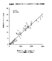
図4は、成人男子3人の3日間の絶食(Fasting )行動に於ける延べ101回測定での呼気中のアセトン濃度(ppm )と、血中ケトン体濃度(アセト酢酸+3−OHBA:μmol/l)との関係を示すグラフである。図から判るように、両者は優れた相関を示す(R=0.970)。尚、呼気は図1に示す装置で31.4μlの呼気サンプルを分取し、PIDを検出器とし清浄空気(20ml/分)をキャリアガスに用いて分析した。また血中ケトン体濃度は、酵素法(ケトレックス/KETO340:三和化学研究所製)により測定した。
【0033】
【発明の効果】
以上説明したように、本発明は、マウスピースから吹き込んだ呼気を呼気排出経路の出口側に設けた流量センサで計量しながら排出し、排出量が死腔容量を越えた段階で、呼気排出経路の途中から呼気吸引経路の一部をなす秤量バルブの秤量弁路に呼気サンプルを吸引分取し、次いで秤量弁路を呼気測定経路に組み込み、測定対象の微量な呼気ガス成分をカラムで分離してガスセンサで検出して濃度測定するものである。
従って、以下のような特徴を有する。
1)測定操作は、スタンバイの状態でマウスピースから呼気を自然に呼出させるだけであるので、慣れない被検者でも誤作動無しで測定できる。また、施術者に特別な教育訓練を施す必要は無いし特別な操作担当者も不要となり、新しい検査としてルーチン化されても医療従事者の負担にならない。しかも、短時間に測定結果が判明し、そのデータが自動記録されるので診療にすぐ対応できる。
2)呼気は、死腔容量を越えた段階で自動的にサンプリングされるので、呼気サンプルから死腔部分が確実に排除され、精確な分析が可能となる。
3)呼気吸引経路を呼気排出経路の途中に連結することにより、検出器が要求する微量の呼気サンプルを大量に排出される呼気中から死腔部分を除いた状態で容易に分取できる。
4)秤量バルブの秤量弁路を呼気吸引経路から呼気測定経路に切り換えるだけでサンプリングが行なわれるので、機構が簡便であるとともに、呼気サンプルの分取が正確且つ確実に行え、精確な分析が可能となる。
5)標準ガス供給経路を組み込むことにより、分析装置のキャリブレーションが正確且つ確実に行なえる。
6)呼気採取管の内壁を加温しておくので、呼気中の微量成分の損失が無く、精度の良い測定値が再現性よく得られる。
7)装置が小型化するため、ベッドサイド機器として、また救急車などの車載機器として、場所を選ばず使用できる。更に、測定結果は迅速(数分)に判明し且つ記録されるので即時に診療データとして活用できるなど、実地 診療上での応用範囲を広げるものである。
8)装置は部品構成が簡単であるので、低価格で製作できる。また消耗品としてはカラムの充填剤程度であるので、測定コストは極めて安価となる。
9)尚、呼気は無侵襲的な検体であり、被検者に肉体的、精神的苦痛や恐怖感、圧迫感を与えない。また、血液による感染も危惧する必要がなくなる。そのため、負荷試験などの繰り返し測定や治療中のモニターなどの連続観察において、被検者の負担が完全に解消する。しかも、即時に検査結果が得られるため、必然的に病気の早期発見ができる。
10)呼気は、血液に比べて遥かに手軽且つ迅速に測定結果が得られるし、尿や唾液、汗などの非観血無侵襲臨床検査方法に比べてより正確な情報が多いため、臨床報告例が急速に増加する可能性がある。その結果、いままで不明であったある特定ガス測定が新たな疾病の診断や同定などに役立つなど、現時点では予測できない未知の現象が解明されるなど、医学上に大きな貢献をなすと思われる。
【図面の簡単な説明】
【図1】本発明に係る呼気中の特定ガス成分の分析装置の一例を示す、ブロック図である。
【図2】秤量バルブを含む呼気吸引経路の一例を部分的に示す模式図で、(a)は呼気吸引時の状態、(b)は呼気測定時の状態を示す。また(c)は、標準ガス吸引時の状態、(d)は標準ガス測定時の状態を示す。
【図3】秤量バルブを含む呼気排出経路の他の例を部分的に示す模式図で、(a)は呼気吸引時の状態、(b)は呼気測定時の状態を示す。
【図4】呼気中のアセトン濃度(ppm )と、血中ケトン体濃度(アセト酢酸+3−OHBA:μmol/l)との関係を示すグラフである。
【符号の説明】
1 呼気中の特定ガス成分の分析装置 16 キャリアガス供給部
2 呼気排出経路 17 カラム
3 呼気吸引経路 18 検出器
4 呼気測定経路 24 標準ガス供給経路
5 演算処理装置 25 標準ガス供給部
8 呼気採取管 26 吸引ポンプ
9 流量センサ B 呼気
10 呼気排出管 S 呼気サンプル
11 マウスピース C キャリアガス
12 吸引路 St 標準ガス
13 秤量バルブ
14 秤量弁路
15 吸引ポンプ[0001]
BACKGROUND OF THE INVENTION
The present invention relates to an improvement in a clinical test method and apparatus using exhaled breath as a specimen, and a case where a minute amount of gas component concentration contained in a breath sample of a subject is measured using a non-selective small and highly sensitive detector. The present invention relates to a device that reliably excludes a dead space from exhaled breath that a subject calls and collects a small amount of exhaled sample simply, reliably and accurately for analysis.
[0002]
[Prior art]
Exhalation is one that is continuously and intermittently released as long as a person (or animal) maintains life. Moreover, since a small amount of volatile components in the mixed venous blood flowing through the alveolar capillaries move into exhaled gas by gas exchange, it is presumed that there is a correlation between exhaled air and blood with respect to the volatile components. In addition, since it is possible to perform differential measurement of volatile components, which is difficult in blood analysis, and it is non-invasive unlike blood, exhaled breath can be said to be an ideal sample for clinical biochemical examination.
[0003]
However, exhalation has not been used so far as a specimen for clinical biochemistry. This is due to the preconception that the exhaled breath should not be a sample for clinical biochemistry, etc., and secondly, the target gas in the exhaled breath is extremely low (ppb units at most ppm) Therefore, it is possible to measure for the first time by a combination of a concentration device for trace components and a large high-sensitivity gas detection device. Therefore, the measurement is performed only in a laboratory in which an expert operates special equipment and tools, and there are only a few clinical research reports.
[0004]
In addition, even if the exhaled air is collected in a container, it takes a place for storage and transportation, and some gas components are unstable, so unlike the blood, it is transported to an analysis center etc. and analyzed with a large device. It is not easy to do. Therefore, clinical biochemical tests using breath as a specimen inevitably face-to-face, such as bedside tests, prehospital tests in ambulances, screening tests during medical treatment, and patient status monitoring (continuous monitoring). It seems to be used effectively only when the measurer (analyst) and the subject (patient) measure face-to-face.
[0005]
Therefore, as described above, an apparatus combining a concentrator and a large-scale high-sensitivity gas detection apparatus performed on some laboratory scales is not practically useful, and is small, portable, and highly sensitive while operating. An inspection apparatus that is simple and excellent in safety and measurement speed is required. Of course, data reliability and economic efficiency are also required. In addition, the moisture in the breath can be condensed on the wall of the container to dissolve and absorb a small amount of gas components, so that the breath is directly sucked from the subject (patient) into the testing device and used for measurement. Is preferred.
[0006]
[Problems to be solved by the invention]
From such a point of view, the present inventors have intensively studied to establish a clinical laboratory technique using breath as a specimen, and used a highly sensitive PID (Photo Ionization Detector) as a detector. An exhalation analyzer was developed (Japanese Patent Laid-Open No. 5-160341).
[0007]
However, this apparatus has a configuration in which exhaled air is forcibly sucked by a pump and discharged out of the system. Accordingly, since the breath is sucked even when the breath is little or stopped, the breath sample may be mixed with atmospheric components. Moreover, since the removal of the dead space part is managed by the rotation time of the pump, there is a possibility that the exhaled air in the dead space part may be mixed into the exhaled sample for the same reason. Furthermore, a three-way electromagnetic valve is provided at two locations in the middle of discharging exhalation out of the system, and the space between them is used as a sample measuring section. However, since the photoionization detector requires only a small amount of exhalation sample, the exhalation discharge tube has to be thin, and thus there is a problem that it takes time to eliminate exhalation in the dead space.
[0008]
The dead space is the dead space, and the exhaled air in this part is a mixture of “exhaled air” from the alveolar air and the inhaled “atmosphere”. ) Cannot be treated as. The dead space volume is about 150-200 ml for adults, and the first insufflation part (initial exhalation) must not be handled as a sample and must be discarded. In other words, the exhalation sample cannot be reliable unless it is the end exhalation excluding this.
[0009]
[Means for Solving the Problems]
From the above point of view, the present inventors reliably exhale exhalation in the dead space portion, and can accurately and accurately collect a small amount of exhalation sample from exhaled exhalation, and have a simple structure and low cost. As a result of earnest research aimed at developing a method and apparatus for analyzing a specific gas component in exhaled air that can be converted into a breath, the present invention has been completed. Hereinafter, the present invention will be described in detail.
[0010]
The analyzer of the present invention employs human breath as a specimen, and separates and measures a trace amount of chemical substance in breath exhaled by a subject to obtain various clinical biochemical information.
[0011]
The analyzer of the present invention (analyzer for a specific gas component in exhaled breath) is roughly divided into an exhalation exhaust path for naturally exhaling exhaled breath from the mouthpiece, and an exhaled breath sample from the middle of the exhaled exhaust path. It comprises an exhalation suction path to be taken, an exhalation measurement path for analyzing a weighed exhalation sample, and a processing unit. The exhalation discharge path is composed of an exhalation collection tube having an inner wall heating function and a mouthpiece attached to the tip, and an exhalation discharge tube incorporating a flow sensor. The exhalation suction path is composed of a weighing valve path of a weighing valve connected in the middle of the exhalation discharge path and a suction device for sucking an exhalation sample into the weighing valve path. The expiration measurement path is composed of a carrier gas supply unit, a weighing valve path of a weighing valve, a column, a detector, and a pipe line connecting these. Here, the weighing valve is incorporated in both the exhalation suction path and the exhalation measurement path, and the weighing valve path is alternately switched to both paths. In addition, the exhalation exhaust pipe, the weighing valve, the column, the detector and the pipe line connecting them are housed in a thermostatic bath. The detector is a small high-sensitivity detector that outputs a measurement signal according to the amount of ionization by ionizing a minute amount of gas components by irradiation with ultraviolet rays or radiation, specifically, a photoionization detector (PID), ion transfer A degree spectrum detector (IMS), an electron capture ion detector (ECD), a flame ionization detector (FID), or a flame photometric detector (FPD) is used. The arithmetic processing unit also performs monitoring of the flow rate sensor, switching of the weighing valve path, storage of the calibration curve, calculation and storage of the concentration of the specific gas component, and the like.
[0012]
Next, it is desirable to heat the breath collection tube of the breath measurement path so that the inner surface thereof is equal to or higher than the body temperature, for example, 36 to 100 ° C., more preferably about 40 to 50 ° C. This is to prevent moisture in the exhalation from condensing and adhering to the inner wall of the exhalation collection tube and dissolving and adsorbing the gas component therein. In order to heat, a heating element may be disposed around or inside the breath collection tube, or the tube may be formed of a material having a heat generating property, and the outer periphery thereof may be covered with a heat insulating material. A temperature control mechanism may be incorporated. If the inner diameter of the exhalation sampling tube is too thin, a feeling of resistance will be generated in inhaling exhalation, and if it is too thick, turbulence will be generated inside, and exhalation in the dead space will be mixed with the end exhalation or the weighing valve path will be too short. Therefore, the inner diameter of the breath collection tube may be about 4 to 20 mmφ, more preferably 6 to 10 mmφ. The outer diameter is about 3 to 10 mm larger than the inner diameter due to a heat insulating material or the like. The mouthpiece attached to the breath collection tube is hygienic when it is of a disposable type.
[0013]
The exhalation discharge pipe is connected to the exhalation collection pipe through a weighing valve with substantially the same inner diameter as the exhalation collection pipe, and a flow sensor is incorporated therein. The flow sensor measures the amount of exhaled breath that is spontaneously called, and can be used to measure the exhaled amount directly or to measure the outflow rate of exhaled breath. In the latter case, the expiratory volume is determined from the cross-sectional area of the expiratory discharge pipe.
[0014]
The exhalation suction path is composed of a weighing valve path of a weighing valve connected in the middle of the exhalation discharge path and a suction device for sucking an exhalation sample into the weighing valve path. The connection between the exhalation discharge path and the weighing valve path of the weighing valve may be such that the weighing valve path is opened directly into the exhalation discharge path, or the suction path is branched from the middle of the exhalation discharge path and this suction path is used as the weighing valve path. You may connect. The weighing valve is incorporated in both the exhalation suction path and the exhalation measurement path, and the weighing valve path is alternately switched to both paths, and the exhalation sample is weighed and collected by this weighing valve path. The The weighing valve path is switched by various types of drive types such as a slide type and a rotary type. On the other hand, the breath sample is sucked by a suction device such as a suction pump or a syringe. However, this suction does not need to be accurately performed such as weighing, and it is only necessary to fill the weighing valve passage with the breath sample. Therefore, if the capacity of the weighing valve path is taken into consideration and suction is performed in excess of that capacity, an accurate exhalation sample weighing is automatically performed by the weighing valve path. When the required amount of suction is finished, the suction device is stopped. Since the volume of the breath sample is 10 to 1000 μl, more preferably 100 to 600 μl, the inner dimension of the weighing valve is determined accordingly. For example, if the inner diameter of the weighing valve path is 3 mm, the inner volume is about 140 μl when the length is 20 mm. If it is desired to lengthen the weighing valve path, a sample loop may be added to the outside.
[0015]
On the other hand, the breath measurement path includes a carrier gas supply unit, a weighing valve path of a weighing valve, a column, a detector, and a pipe line connecting these. The carrier gas supply unit sends out a carrier gas for sending the breath sample into the separation column, and a small gas cylinder is preferable as the supply source in view of the portability of the present inspection apparatus. However, a large gas cylinder can also be used when the inspection apparatus is installed and used at a certain location. Inexpensive clean air or nitrogen gas can be used as the carrier gas, but helium and other commonly used gases can be used. In the case of clean air, the atmospheric air may be supplied by a compression pump without filling the gas cylinder. However, in order to eliminate the influence of a trace amount of gas components in the atmosphere, it is necessary to clean with an air filter incorporating an adsorbent or the like.
[0016]
Detectors used in the present invention include PID (Photo Ionization Detector: photoionization detector), IMS (Ion Mobility Spectrometer: ion mobility spectrum detector), ECD (Electron Capture Detector: electron capture ion detector), FID ( Flame Ionization Detector (Hydrogen ion detector) or FPD (Flame Photometric Detector: Flame Photometric Detector), the target gas components in the breath are ionized by irradiation with light or radiation, etc. A type that outputs a measurement signal accordingly is used. These detectors are small and extremely sensitive, so only a small amount of sample is required. Among these, PID is the most preferable because it uses radiation and does not involve combustion of hydrogen gas. In addition, since these are all non-selective, if they are separated by a column, various exhaled gas components such as ketone bodies (mainly acetone), lower hydrocarbons such as methane, ethane, and pentane, ammonia, methyl mercaptan, and acetaldehyde. Etc. can be measured. Since the column has a very small amount of breath sample, a capillary column is usually preferable, but a packed column is also used depending on the sample amount. If a plurality of exhaled gas components can be separated in the column, a plurality of detection target gases can be measured. It should be noted that the weighing valve, exhalation exhaust pipe, detector, and these connecting pipes including the separation column are housed in a thermostatic bath in order to prevent moisture condensation in the exhalation, and the same as the exhalation collection pipe. The temperature may be kept at 100 ° C, more preferably about 40-50 ° C.
[0017]
The main part of the arithmetic processing unit is a microcomputer, which receives the measurement signal output from the detector, performs arithmetic processing, calculates the concentration of the gas component to be detected from a pre-stored calibration curve, and stores it as clinical test data To do. Also, the operation program for the entire device, such as monitoring the flow sensor and switching the weighing valve path, outputting signals to output devices such as display devices (displays) and recording devices (printers), and accepting input signals from the keyboard Manage.
[0018]
Next, sensitivity calibration (calibration) of the analyzer will be described. Since the analyzer of the present invention uses a gas body as a measurement object, the measured value may still be influenced by other fluctuation factors even if it is stored in a thermostat. That is, the measured value may deviate from the true value due to various factors such as a change with time of the column and the detector and variations in the operation of the detector. Therefore, it is desirable to adjust the sensitivity at the start of daily measurement or at an appropriate time. Of these, zero adjustment is performed by supplying a carrier gas to the breath measurement path. On the other hand, sensitivity adjustment is performed using high-purity nitrogen gas (standard gas) containing a predetermined concentration of the gas component to be measured. That is, the weighing valve path of the weighing valve is incorporated in the standard gas supply path connected to the standard gas supply unit, and the standard gas of known concentration is sucked and filled into the weighing valve path, and then the breath measurement is performed by separating the weighing valve path from the standard gas supply path. Incorporated into the path, the standard gas concentration is measured, and the analytical value is calibrated. The standard gas may be corrected at three points using low and high concentrations of two types. Therefore, the weighing valve is configured such that the weighing valve path is switched to the exhalation suction path, the exhalation measurement path, and the standard gas supply path, and the switching is performed according to an instruction from the arithmetic processing unit. The standard gas can be blown into the exhalation discharge path or sucked from the suction path of the exhalation suction path. However, the former consumes a large amount of standard gas, and the latter has a difficulty in complicating the configuration and operation, such as attaching a three-way cock to the branch part.
[0019]
In using the test apparatus of the present invention having the above-described configuration, first, (1) the mouthpiece attached to the breath collection tube is added to the mouth, the measurable state is confirmed or the measurement start button is pressed, Call exhalation. (2) Exhaled air is discharged out of the system through the exhalation discharge tube, but expired from the middle of the exhalation discharge route when the amount of exhalation corresponding to the dead space volume (about 150 to 200 ml) is exhausted. Aspirate the breath sample into the weighing valve path of the weighing valve that forms part of the suction path. (3) Subsequently, the weighing valve path is separated from the exhalation suction path and incorporated in the exhalation measurement path connected to the carrier gas supply unit. {Circle around (4)} The exhaled breath sample in the weighing valve path is sent to the column together with the carrier gas to separate the specific gas component, and the specific gas component is detected by the detector. (5) The output of the detector is arithmetically processed by an arithmetic processing unit. Here, the concentration of a specific gas component to be detected is calculated from a calibration curve stored in advance, and stored as clinical test data or signaled to an output device. Is output. One measurement is completed in a few minutes depending on the type of gas to be detected, and the concentration of a single gas component or a plurality of specific gas components in exhaled breath can be measured quickly and accurately. {Circle around (6)} The calibration of the analyzer is carried out by incorporating the weighing valve path of the weighing valve into the exhalation measurement path and allowing the carrier gas to flow and setting the measured value at that time to zero. In addition, the weighing valve path of the weighing valve is incorporated into the standard gas supply path, the standard gas having a known concentration is collected, and the measured value at that time is calibrated to the standard gas concentration.
[0020]
DETAILED DESCRIPTION OF THE INVENTION
Next, the present invention will be described in more detail based on a preferred embodiment shown in the drawings. The present invention is not limited to the illustrated one. FIG. 1 shows an example of a block diagram of an
[0021]
The
[0022]
The
[0023]
The
[0024]
The weighing
[0025]
Next, the
[0026]
The
[0027]
The standard
[0028]
With respect to the standard
[0029]
The main part of the
[0030]
Next, the sorting operation of the device of the present invention will be described with reference to FIG. First, after confirming the measurable state (standby state), the subject holds the mouthpiece and calls the exhalation B. When exhaled air corresponding to the volume of the dead space in the exhaled air is discharged (called), the exhaled air sample S is aspirated into the weighing valve path of the weighing valve that forms part of the exhalation suction path from the middle of the exhalation discharging path. To be taken (state of FIG. 2A). Meanwhile, the subject calls for exhalation to the end. The weighing valve path is switched to the breath measurement path, and the breath sample S in the weighing valve path is sent to the
[0031]
The sorting operation of the apparatus of the present invention having a different standard gas supply path will be described with reference to FIG. In this apparatus, a standard
[0032]
FIG. 4 shows the concentration of acetone in the breath (ppm) and the blood ketone body concentration (acetoacetic acid + 3-OHBA: μmol / μm) in a total of 101 measurements in 3 days of fasting behavior of 3 adult males. It is a graph which shows the relationship with l). As can be seen from the figure, both show an excellent correlation (R = 0.970). For exhalation, 31.4 μl of exhalation sample was collected with the apparatus shown in FIG. 1 and analyzed using PID as a detector and clean air (20 ml / min) as a carrier gas. The blood ketone body concentration was measured by an enzymatic method (Ketrex / KETO340: manufactured by Sanwa Chemical Laboratory).
[0033]
【The invention's effect】
As described above, the present invention discharges the exhaled air blown from the mouthpiece while measuring it with a flow sensor provided on the outlet side of the exhaled air discharge route, and when the discharged amount exceeds the dead space capacity, The exhalation sample is aspirated into the weighing valve path of the weighing valve that forms part of the exhalation suction path, and then the weighing valve path is installed in the exhalation measurement path, and the trace exhalation gas component to be measured is separated by the column. The concentration is measured by detecting with a gas sensor.
Therefore, it has the following characteristics.
1) Since the measurement operation only allows the exhalation to be spontaneously called from the mouthpiece in the standby state, even an unaccustomed subject can measure without malfunction. In addition, it is not necessary to give special training to the practitioner, and no special operator is required, and even if it is routineized as a new examination, it does not burden the medical staff. In addition, the measurement results are found in a short time, and the data is automatically recorded, so that it is possible to respond immediately to medical care.
2) Since the exhaled breath is automatically sampled at a stage exceeding the dead space capacity, the dead space portion is surely excluded from the exhaled sample, and an accurate analysis becomes possible.
3) By connecting the exhalation suction path in the middle of the exhalation discharge path, a small amount of exhalation sample required by the detector can be easily collected in a state where the dead space portion is removed from the exhaled gas that is exhausted in large quantities.
4) Sampling is performed simply by switching the weighing valve path of the weighing valve from the exhalation suction path to the exhalation measurement path, so that the mechanism is simple and the exhalation sample can be collected accurately and reliably for accurate analysis. It becomes.
5) By incorporating the standard gas supply path, the analyzer can be calibrated accurately and reliably.
6) Since the inner wall of the breath collection tube is heated, there is no loss of trace components in the breath, and accurate measurement values can be obtained with good reproducibility.
7) Since the device is downsized, it can be used as a bedside device or an in-vehicle device such as an ambulance regardless of location. Furthermore, since the measurement results are quickly identified (several minutes) and recorded, they can be used as medical data immediately, expanding the range of practical medical applications.
8) Since the device has a simple component structure, it can be manufactured at low cost. In addition, since the consumable is about the same as the packing material of the column, the measurement cost is extremely low.
9) In addition, exhaled breath is a non-invasive specimen, and does not give physical or mental pain, fear or pressure to the subject. Moreover, there is no need to worry about blood infection. Therefore, the burden on the subject is completely eliminated in repeated observations such as stress tests and continuous observation such as monitoring during treatment. Moreover, since the test results can be obtained immediately, it is inevitably possible to detect the disease early.
10) Exhaled breath is much easier and faster than blood, and more accurate information than non-invasive non-invasive clinical testing methods such as urine, saliva and sweat. Examples can increase rapidly. As a result, the measurement of a specific gas, which has been unknown until now, is useful for the diagnosis and identification of new diseases, and it is thought that it will make a significant contribution to medicine, such as the elucidation of unknown phenomena that cannot be predicted at present.
[Brief description of the drawings]
FIG. 1 is a block diagram showing an example of an analyzer for specific gas components in exhaled breath according to the present invention.
FIG. 2 is a schematic diagram partially showing an example of an exhalation suction path including a weighing valve, where (a) shows a state during exhalation and (b) shows a state during exhalation measurement. (C) shows the state at the time of standard gas suction, and (d) shows the state at the time of standard gas measurement.
FIGS. 3A and 3B are schematic views partially showing another example of an exhalation discharge path including a weighing valve, in which FIG. 3A shows a state during exhalation and FIG. 3B shows a state during exhalation measurement.
FIG. 4 is a graph showing the relationship between the acetone concentration (ppm) in exhaled breath and the blood ketone body concentration (acetoacetic acid + 3-OHBA: μmol / l).
[Explanation of symbols]
1 Analyzer for specific gas components in exhaled
2
3
4
5
8
9 Flow sensor B Exhalation
10 Exhalation tube S Exhalation sample
11 Mouthpiece C Carrier gas
12 Suction channel St Standard gas
13 Weighing valve
14 Weighing valve
15 Suction pump
Claims (1)
該呼気排出経路から呼気サンプルを秤量分取する呼気吸引経路と、
本分析装置の感度較正のための標準ガス供給経路と、
秤量分取した呼気サンプルを分析する呼気測定経路及び演算処理装置を含むものであって、
呼気排出経路は、内壁加温機能を備え先端にマウスピースが装着される呼気採取管と流量センサを組み込んだ呼気排出管から構成され、
呼気吸引経路は、呼気排出経路の途中に連結された秤量バルブの秤量弁路と該秤量弁路に呼気サンプルを吸引する吸引装置から構成され、
標準ガス供給経路は、標準ガス供給部と秤量バルブの秤量弁路及び、該秤量弁路に標準ガスを吸引分取する吸引ポンプから構成され、
呼気測定経路は、キャリアガス供給部と秤量バルブの秤量弁路、カラム、検出器、及びこれらを連結する管路から構成され、
且つ排出管、秤量バルブ、カラム、検出器及びこれらを連結する管路は恒温槽内に収納されるとともに、演算処理装置で流量センサの監視と秤量弁路の切替え、検量線の記憶と特定ガス成分の濃度の算出や記憶を行ない、且つ該吸引装置は該流量センサが一定量の通過を検知した後作動するものであり、更に秤量バルブはその秤量弁路が呼気吸引経路と呼気測定経路及び標準ガス供給経路に相互に切り換えられるようになっていることを特徴とする呼気中の特定ガス成分の分析装置。An exhalation discharge route that naturally discharges exhaled breath from the mouthpiece;
An exhalation suction path for weighing and sampling an exhalation sample from the exhalation discharge path;
Standard gas supply path for sensitivity calibration of the analyzer ,
Including an expiration measurement path for analyzing a weighed exhalation sample and an arithmetic processing unit,
The exhalation discharge path is composed of an exhalation collection pipe with a mouthpiece attached to the tip with an inner wall heating function and an exhalation discharge pipe incorporating a flow sensor,
The exhalation suction path is composed of a weighing valve path of a weighing valve connected in the middle of the exhalation discharge path and a suction device for sucking an exhalation sample into the weighing valve path,
The standard gas supply path is composed of a standard gas supply unit, a weighing valve path of the weighing valve, and a suction pump for sucking and separating the standard gas into the weighing valve path,
The breath measurement path is composed of a carrier gas supply unit and a weighing valve path of a weighing valve, a column, a detector, and a pipe line connecting these,
In addition, the discharge pipe, weighing valve, column, detector and the pipe connecting them are housed in a constant temperature bath, and the processing unit monitors the flow sensor, switches the weighing valve, stores the calibration curve, and the specified gas. The concentration of the component is calculated and stored, and the suction device operates after the flow sensor detects the passage of a certain amount, and the weighing valve has a weighing valve path that is an expiration suction path, an expiration measurement path, and A device for analyzing a specific gas component in exhaled breath, wherein the analyzer is switched to a standard gas supply path.
Priority Applications (1)
| Application Number | Priority Date | Filing Date | Title |
|---|---|---|---|
| JP17743896A JP4028006B2 (en) | 1996-06-17 | 1996-06-17 | Analyzer for specific gas components in exhaled breath |
Applications Claiming Priority (1)
| Application Number | Priority Date | Filing Date | Title |
|---|---|---|---|
| JP17743896A JP4028006B2 (en) | 1996-06-17 | 1996-06-17 | Analyzer for specific gas components in exhaled breath |
Related Child Applications (1)
| Application Number | Title | Priority Date | Filing Date |
|---|---|---|---|
| JP2003170733A Division JP2004077467A (en) | 2003-06-16 | 2003-06-16 | Sampling method and device of end expiration |
Publications (2)
| Publication Number | Publication Date |
|---|---|
| JPH10187A JPH10187A (en) | 1998-01-06 |
| JP4028006B2 true JP4028006B2 (en) | 2007-12-26 |
Family
ID=16030954
Family Applications (1)
| Application Number | Title | Priority Date | Filing Date |
|---|---|---|---|
| JP17743896A Expired - Fee Related JP4028006B2 (en) | 1996-06-17 | 1996-06-17 | Analyzer for specific gas components in exhaled breath |
Country Status (1)
| Country | Link |
|---|---|
| JP (1) | JP4028006B2 (en) |
Cited By (1)
| Publication number | Priority date | Publication date | Assignee | Title |
|---|---|---|---|---|
| KR101913149B1 (en) * | 2015-11-30 | 2018-10-31 | 세주엔지니어링주식회사 | Gas detector using internal-type standard gas for re-calibration |
Families Citing this family (5)
| Publication number | Priority date | Publication date | Assignee | Title |
|---|---|---|---|---|
| JP4790436B2 (en) * | 2006-02-03 | 2011-10-12 | 東亜ディーケーケー株式会社 | Hydrogen flame ionization analyzer |
| JP5443995B2 (en) * | 2006-12-21 | 2014-03-19 | デカ・プロダクツ・リミテッド・パートナーシップ | System that supports detection of physiological abnormalities |
| WO2011045891A1 (en) * | 2009-10-13 | 2011-04-21 | 株式会社日立製作所 | Ion detecting device |
| CN107595323B (en) * | 2017-10-18 | 2024-03-22 | 中国人民解放军疾病预防控制所 | Portable tubular respiratory cough gas condensation collection device and system thereof |
| JP7087445B2 (en) * | 2018-02-27 | 2022-06-21 | 株式会社リコー | Analytical equipment and analytical method |
Family Cites Families (3)
| Publication number | Priority date | Publication date | Assignee | Title |
|---|---|---|---|---|
| JPH0658919A (en) * | 1992-06-12 | 1994-03-04 | Hideo Ueda | Method and device for analyzing expiration |
| JP3838671B2 (en) * | 1993-10-25 | 2006-10-25 | アークレイ株式会社 | Breath collection device |
| JPH08101095A (en) * | 1994-09-30 | 1996-04-16 | Suzuki Motor Corp | Breath sampling analyzer |
-
1996
- 1996-06-17 JP JP17743896A patent/JP4028006B2/en not_active Expired - Fee Related
Cited By (1)
| Publication number | Priority date | Publication date | Assignee | Title |
|---|---|---|---|---|
| KR101913149B1 (en) * | 2015-11-30 | 2018-10-31 | 세주엔지니어링주식회사 | Gas detector using internal-type standard gas for re-calibration |
Also Published As
| Publication number | Publication date |
|---|---|
| JPH10187A (en) | 1998-01-06 |
Similar Documents
| Publication | Publication Date | Title |
|---|---|---|
| JP3838671B2 (en) | Breath collection device | |
| US5425374A (en) | Device and method for expiratory air examination | |
| US5042501A (en) | Apparatus and method for analysis of expired breath | |
| EP1480557B1 (en) | Breath collection system | |
| JP5716194B2 (en) | Apparatus and method for analyzing gas and alveolar air components in the oral cavity | |
| US4735777A (en) | Instrument for parallel analysis of metabolites in human urine and expired air | |
| Schon et al. | Versatile breath sampler for online gas sensor analysis | |
| KR20160047565A (en) | Universal breath analysis sampling device | |
| JPH07120463A (en) | Concentration correction method for aspiration component and aspiration analysis device | |
| JP2017534887A (en) | Breath analysis system and method for screening for infectious diseases | |
| JPH0658919A (en) | Method and device for analyzing expiration | |
| JPH10227725A (en) | Breath analyzer | |
| JP2004077467A (en) | Sampling method and device of end expiration | |
| EP0574027A2 (en) | Expired gas analytical method and device | |
| JP3525157B2 (en) | Intestinal gas component measurement method and flatus detection method | |
| JPH10186A (en) | Method and device of analyzing specified gas component in expired air | |
| JP4028006B2 (en) | Analyzer for specific gas components in exhaled breath | |
| LT4159B (en) | Blood gas probe | |
| KR101910017B1 (en) | Apparatus for diagnosing diseases using exhaled breath analysis | |
| JPH0647047A (en) | Method for clinical inspection of expiration and device therefor | |
| RU117078U1 (en) | SAMPLE FOR GAS ANALYSIS OF EXHAUSTED AIR | |
| JP4452783B2 (en) | Cirrhosis test method and apparatus using breath analysis apparatus | |
| EP0577053A1 (en) | Expired gas sampling method and expired gas collecting tube | |
| JPH10227777A (en) | Breath analyzer | |
| JP2004093555A (en) | Intestinal gas component measuring device and flatus detection device |
Legal Events
| Date | Code | Title | Description |
|---|---|---|---|
| A521 | Written amendment |
Free format text: JAPANESE INTERMEDIATE CODE: A523 Effective date: 20031113 |
|
| A977 | Report on retrieval |
Free format text: JAPANESE INTERMEDIATE CODE: A971007 Effective date: 20041118 |
|
| A131 | Notification of reasons for refusal |
Free format text: JAPANESE INTERMEDIATE CODE: A131 Effective date: 20041130 |
|
| A02 | Decision of refusal |
Free format text: JAPANESE INTERMEDIATE CODE: A02 Effective date: 20050517 |
|
| A521 | Written amendment |
Free format text: JAPANESE INTERMEDIATE CODE: A523 Effective date: 20050614 |
|
| A911 | Transfer to examiner for re-examination before appeal (zenchi) |
Free format text: JAPANESE INTERMEDIATE CODE: A911 Effective date: 20050801 |
|
| A912 | Re-examination (zenchi) completed and case transferred to appeal board |
Free format text: JAPANESE INTERMEDIATE CODE: A912 Effective date: 20050819 |
|
| A521 | Written amendment |
Free format text: JAPANESE INTERMEDIATE CODE: A523 Effective date: 20070822 |
|
| A711 | Notification of change in applicant |
Free format text: JAPANESE INTERMEDIATE CODE: A711 Effective date: 20071011 |
|
| A61 | First payment of annual fees (during grant procedure) |
Free format text: JAPANESE INTERMEDIATE CODE: A61 Effective date: 20071011 |
|
| FPAY | Renewal fee payment (event date is renewal date of database) |
Free format text: PAYMENT UNTIL: 20101019 Year of fee payment: 3 |
|
| R150 | Certificate of patent or registration of utility model |
Free format text: JAPANESE INTERMEDIATE CODE: R150 |
|
| A521 | Written amendment |
Free format text: JAPANESE INTERMEDIATE CODE: A821 Effective date: 20071011 |
|
| FPAY | Renewal fee payment (event date is renewal date of database) |
Free format text: PAYMENT UNTIL: 20101019 Year of fee payment: 3 |
|
| FPAY | Renewal fee payment (event date is renewal date of database) |
Free format text: PAYMENT UNTIL: 20111019 Year of fee payment: 4 |
|
| LAPS | Cancellation because of no payment of annual fees |