JP4020666B2 - Shaft coupling - Google Patents
Shaft coupling Download PDFInfo
- Publication number
- JP4020666B2 JP4020666B2 JP2002067852A JP2002067852A JP4020666B2 JP 4020666 B2 JP4020666 B2 JP 4020666B2 JP 2002067852 A JP2002067852 A JP 2002067852A JP 2002067852 A JP2002067852 A JP 2002067852A JP 4020666 B2 JP4020666 B2 JP 4020666B2
- Authority
- JP
- Japan
- Prior art keywords
- resin plate
- rubber
- shaft
- shaft coupling
- plate member
- Prior art date
- Legal status (The legal status is an assumption and is not a legal conclusion. Google has not performed a legal analysis and makes no representation as to the accuracy of the status listed.)
- Expired - Fee Related
Links
Images


Landscapes
- Power Steering Mechanism (AREA)
Description
【0001】
【発明の属する技術分野】
本発明は、駆動軸と被動軸の間に設けられて駆動軸の回転を被動軸に伝達する軸継手に関する。
【0002】
【従来の技術】
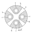
従来より、特開平7−71471号公報に開示されているように、駆動軸と被動軸の間に設けられて回転力を伝達する軸継手が知られている。この種の軸継手は、例えば、自動車のステアリングシャフトやプロペラシャフトに設けられる。ここでは、上記公報に開示されている軸継手について、図25を参照しながら説明する。
【0003】
この軸継手は、一つの樹脂盤体aと、四つのゴム弾性体bと、四つの筒体cとを備えており、全体としてやや厚肉の円板状に形成されている。合成樹脂製の樹脂盤体aは、円板の四箇所を切り欠いたような十字状に形成されている。ゴム製の各ゴム弾性体bは、樹脂盤体aの切欠き部分に対応した形状に形成され、この切欠き部分にはめ込まれた状態で樹脂盤体aと加硫接着されている。金属製の筒体cは、短いパイプ状に形成され、各ゴム弾性体bに一つずつ設けられている。各筒体cは、ゴム弾性体bをその厚さ方向へ貫通し、ゴム弾性体bと加硫接着されている。また、四つの筒体cは、一つのピッチ円上に90°間隔で配置されている。
【0004】
この軸継手では、180°離れて位置する二つの筒体cに駆動軸が係合され、残りの二つの筒体cに被動軸が係合される。そして、この軸継手は、駆動軸の回転力を被動軸へと伝達する。また、この軸継手は、駆動軸や被動軸の軸方向と捻り方向の振動等を緩和できるように構成されている。例えば、軸方向の振動が軸継手に加えられると、図25における紙面の手前側又は奥側へ筒体cが移動し、その際にゴム弾性体bが変形することで振動が緩和される。また、捻り方向の振動が軸継手に加えられると、図25における円周方向へ筒体cが移動し、その際にゴム弾性体bが変形することで振動が緩和される。
【0005】
【発明が解決しようとする課題】
上述のように、上記軸継手においては、それぞれ材料の異なる樹脂盤体aとゴム弾性体bと筒体cとが互いに加硫接着されている。一方、この軸継手を廃棄する際には、各部材のリサイクルを行うために、材料ごとに部材を分別するのが望ましい。ところが、上記軸継手では、材料の異なる部材が互いに加硫接着されている。このため、上記軸継手の廃棄時に部材を材料ごとに分別する作業に多大な時間を要し、リサイクル性に劣るという問題があった。
【0006】
また、軸継手の製造時においても、各部材を加硫接着する工程が必要となる。このため、軸継手の製造工程の複雑化や生産効率の低下を招き、ひいては製造コストの増大を招くと行った問題もあった。
【0007】
本発明は、かかる点に鑑みてなされたものであり、その目的とするところは、異なる材料の部材で構成された軸継手のリサイクル性を向上させ、更にはその製造工程を簡素化することにある。
【0008】
【課題を解決するための手段】
本発明が講じた第1の解決手段は、駆動軸の軸端部及び被動軸の軸端部に複数ずつ設けられた棒状突起部に連結されて駆動軸の回転を被動軸へ伝達する軸継手を対象としている。そして、平板状に形成された平板部と該平板部の前面側に一体形成された複数の突出部とをそれぞれが有すると共に、それぞれの突出部が互いに当接するように向かい合って配置される一対のゴム状弾性部材と、互いに向かい合うゴム状弾性部材の平板部によって挟み込まれる樹脂板部材と、互いに当接し合う2つの上記突出部を貫通するように設けられて駆動軸又は被動軸の棒状突起部が挿通される管状部材とを備え、上記ゴム状弾性部材と樹脂板部材と管状部材とが互いに非接着状態で組み合わされるものである。
【0009】
本発明が講じた第2の解決手段は、上記第1の解決手段において、樹脂板部材には、該樹脂板部材の周側面から中心に向かって延びる切欠き部が複数形成される一方、向かい合う2つの突出部は、上記切欠き部にはめ込まれた状態で互いに当接しているものである。
【0010】
本発明が講じた第3の解決手段は、上記第1の解決手段において、樹脂板部材には、該樹脂板部材を板厚方向に貫通する貫通孔が複数形成される一方、向かい合う2つの突出部は、上記貫通孔に挿入された状態で互いに当接しているものである。
【0011】
本発明が講じた第4の解決手段は、上記第2の解決手段において、樹脂板部材は、その両側面における切欠き部の周囲が座ぐり状に一段低く形成されるものである。
【0012】
本発明が講じた第5の解決手段は、上記第3の解決手段において、樹脂板部材は、その両側面における貫通孔の周囲が座ぐり状に一段低く形成されるものである。
【0013】
本発明が講じた第6の解決手段は、上記第1,第2又は第3の解決手段において、ゴム状弾性部材には、平板部における突出部の周囲と樹脂板部材との間に隙間が形成されるように該平板部の前面側へ盛り上がって樹脂板部材に当接する膨出部が形成されるものである。
【0014】
本発明が講じた第7の解決手段は、上記第1,第2又は第3の解決手段において、複数設けられた管状部材が一つのピッチ円上に配置される一方、樹脂板部材とゴム状弾性部材の相対的な位置は、少なくとも上記ピッチ円の周方向において突出部と樹脂板部材の間に隙間が形成されるように定められるものである。
【0015】
本発明が講じた第8の解決手段は、上記第1,第2又は第3の解決手段において、複数設けられた管状部材が一つのピッチ円上に配置される一方、樹脂板部材とゴム状弾性部材の相対的な位置は、少なくとも上記ピッチ円の半径方向において突出部と樹脂板部材の間に隙間が形成されるように定められるものである。
【0016】
本発明が講じた第9の解決手段は、上記第3の解決手段において、複数設けられた管状部材が一つのピッチ円上に配置され、ゴム状弾性部材の突出部は、樹脂板部材の貫通孔に挿入された状態で該突起部の周側面全体が樹脂板部材と密着するような形状に形成される一方、上記突起部には、上記ピッチ円の半径方向における管状部材の両側に空洞部が一つずつ形成されるものである。
【0017】
−作用−
上記第1の解決手段では、ゴム状弾性部材、樹脂板部材、及び管状部材を互いに非接着状態で組み合わせることによって軸継手が構成される。この軸継手では、樹脂板部材を挟んで2つのゴム状弾性部材が設けられる。互いに向かい合うゴム状弾性部材は、それぞれの平板部が樹脂板部材を挟み込み、それぞれの突出部が互いに当接する。互いに当接して対となった2つの突出部には、1つの管状部材が取り付けられる。つまり、軸継手には、一つのゴム状弾性部材に形成された突出部と同数の管状部材が設けられる。
【0018】
本解決手段の軸継手では、複数設けられた管状部材のうちの半数に駆動軸の棒状突起部が挿通され、残りの半数に被動軸の棒状突起部が挿通される。つまり、この軸継手は、駆動軸の軸端部と被動軸の軸端部とによって挟み込まれた状態となる。従って、樹脂板部材とこれを挟み込むゴム状弾性部材とが非接着状態となる構成であっても、少なくとも軸継手が駆動軸や被動軸に連結された状態において軸継手の形態は保持される。
【0019】
上記第2の解決手段では、樹脂板部材に複数の切欠き部が形成される。各切欠き部は、樹脂板部材の周側面に開口している。樹脂板部材の切欠き部には、ゴム状弾性部材の突出部がはめ込まれる。互いに向かい合って対となる2つの突出部は、1つの切欠き部にはめ込まれた状態で互いに当接する。
【0020】
上記第3の解決手段では、樹脂板部材に複数の貫通孔が形成される。各貫通孔は、樹脂板部材をその板厚方向へ貫通している。樹脂板部材の貫通孔には、ゴム状弾性部材の突出部が挿入される。互いに向かい合って対となる2つの突出部は、1つの貫通孔に挿入された状態で互いに当接する。
【0021】
上記第4の解決手段では、樹脂板部材における切欠き部の周囲が、座ぐり状に一段低く形成される。駆動軸又は被動軸がそれらの軸方向へ変位すると、それに伴って軸継手のゴム状弾性部材が変形する。その際、切欠き部の周囲に形成された一段低い部分の深さに対し、ゴム状弾性部材の変形量がその深さ未満であれば、ゴム状弾性部材の平板部は、樹脂板部材における切欠き部の周縁と接触しない。一方、ゴム状弾性部材の変形量がその深さ以上であれば、ゴム状弾性部材の平板部は、樹脂板部材における切欠き部の周縁と接触する。
【0022】
上記第5の解決手段では、樹脂板部材における貫通孔の周囲が、座ぐり状に一段低く形成される。駆動軸又は被動軸がそれらの軸方向へ変位すると、それに伴って軸継手のゴム状弾性部材が変形する。その際、貫通孔の周囲に形成された一段低い部分の深さに対し、ゴム状弾性部材の変形量がその深さ未満であれば、ゴム状弾性部材の平板部は、樹脂板部材における貫通孔の周縁と接触しない。一方、ゴム状弾性部材の変形量がその深さ以上であれば、ゴム状弾性部材の平板部は、樹脂板部材における貫通孔の周縁と接触する。
【0023】
上記第6の解決手段では、ゴム状弾性部材の平板部に膨出部が形成される。この膨出部は、突出部と同様に平板部の前面側に形成される。本解決手段の軸継手では、この膨出部が樹脂板部材に当接することで、平板部における突出部の周囲と樹脂板部材との間には隙間が形成される。
【0024】
ここで、駆動軸又は被動軸がそれらの軸方向へ変位すると、それに伴って軸継手のゴム状弾性部材が変形する。その際、平板部における突出部の周囲と樹脂板部材との間隔に対し、ゴム状弾性部材の変形量がその間隔未満であれば、平板部における突出部の周囲は、樹脂板部材と接触しない。一方、ゴム状弾性部材の変形量がその間隔以上であれば、平板部における突出部の周囲は、樹脂板部材と接触する。
【0025】
上記第7の解決手段では、複数の管状部材が同一ピッチ円上に配置される。突出部と樹脂板部材の間には、少なくとも管状部材のピッチ円の周方向に隙間が形成される。樹脂板部材とゴム状弾性部材の相対的な位置は、このような隙間が形成されるように定められる。
【0026】
ここで、駆動軸からの回転力が軸継手に伝わると、その回転力によって軸継手のゴム状弾性部材が変形する。その際、ゴム状弾性部材の突出部と樹脂板部材との間隔に対し、ゴム状弾性部材の変形量がその間隔未満であれば、ゴム状弾性部材の突出部は樹脂板部材と接触しない。一方、ゴム状弾性部材の変形量がその間隔以上であれば、ゴム状弾性部材の突出部は樹脂板部材と接触する。
【0027】
上記第8の解決手段では、複数の管状部材が同一ピッチ円上に配置される。突出部と樹脂板部材の間には、少なくとも管状部材のピッチ円の半径方向に隙間が形成される。樹脂板部材とゴム状弾性部材の相対的な位置は、このような隙間が形成されるように定められる。
【0028】
上記第9の解決手段では、複数の管状部材が同一ピッチ円上に配置される。ゴム状弾性部材の突出部は、樹脂板部材の貫通孔と同じような形状に形成され、その周側面全体が樹脂板部材と密着する。また、各突出部には、管状部材のピッチ円の半径方向における管状部材の両側に空洞部が形成される。従って、突出部を貫通する管状部材のピッチ円の半径方向へ多少傾いても、この傾きは空洞部が変形することによって吸収される。
【0029】
【発明の効果】
本発明では、軸継手の構造を樹脂板部材が一対のゴム状弾性部材で挟み込まれる構造とし、その上でゴム状弾性部材、樹脂板部材、及び管状部材を互いに非接着状態としている。このため、ゴム状弾性部材と樹脂板部材と管状部材とを互いに接着することなく、少なくとも駆動軸や被動軸の軸端部に軸継手が連結された状態でこれら3種類の部材を互いに組み合わされた状態に保持できる。
【0030】
このように、本発明によれば、軸継手を構成する各部材を互いに接着することなく、一つの軸継手を形成することができる。このため、本発明に係る軸継手の廃棄時には、この軸継手を分解する作業を短時間で容易に行うことができる。また、軸継手の各部材が互いに接着されている場合に比べ、その部材を材料ごとに確実に分別できる。従って、本発明によれば、軸継手を廃棄する際の分別作業を短時間で確実に行うことが可能となり、軸継手のリサイクル性を向上させることができる。
【0031】
また、上述のように、本発明によれば、複数の部材を互いに接着せずに一つの軸継手を構成できる。このため、本発明に係る軸継手の製造時には、部材同士を接着する工程が全く不要となる。従って、本発明によれば、軸継手の製造工程を簡略化してその生産効率を高めることができ、更にはその製造コストの低減を図ることができる。
【0032】
ここで、駆動軸の軸心と被動軸の軸心は完全に一致していないのが普通であり、一方の軸心に対して他方の軸心が傾いている場合も多い。このような場合には、駆動軸や被動軸の棒状突起部が挿通された管状部材が傾けられる。そして、突出部の周側面全体が樹脂板部材と密着していると、傾いた管状部材と樹脂板部材によって突出部が押し潰され、ゴム状弾性部材が変形する際の特性が変化してしまう。
【0033】
これに対し、上記第2の解決手段では、樹脂板部材の切欠き部にゴム状弾性部材の突出部をはめ込んでいる。このため、切欠き部の開口側へ管状部材が傾いた状態でも、管状部材と樹脂板部材に挟まれて突出部が押し潰されることはない。また、上記第8の解決手段では、樹脂板部材とゴム状弾性部材を組み合わせた状態において、突出部と樹脂板部材の間に隙間が形成される。このため、この隙間の方へ管状部材が傾いた状態でも、管状部材と樹脂板部材に挟まれて突出部が押し潰されることはない。また、上記第9の解決手段では、ゴム状弾性部材の突出部に空洞部を形成している。このため、空洞部の方へ管状部材が傾いた状態でも、管状部材と樹脂板部材に挟まれて突出部が押し潰されることはない。従って、これら上記第2,第8,第9の解決手段によれば、傾いた筒状部材と樹脂板部材に挟まれて突出部が押し潰されるのを回避でき、ゴム状弾性部材が変形する際の特性を一定に保つことができる。
【0034】
上記第4,第5,第6の解決手段によれば、駆動軸や被動軸の軸方向へゴム状弾性部材が変形する際の特性を、二段特性とすることができる。具体的に、第4の解決手段によれば、ゴム状弾性部材の平板部が樹脂板部材における切欠き部の周縁に接している状態と接していない状態とで、ゴム状弾性部材のバネ定数を変化させることができる。また、第5の解決手段によれば、ゴム状弾性部材の平板部が樹脂板部材における貫通孔の周縁に接している状態と接していない状態とで、ゴム状弾性部材のバネ定数を変化させることができる。また、第6の解決手段によれば、平板部における突出部の周囲が樹脂板部材に接している状態と接していない状態とで、ゴム状弾性部材のバネ定数を変化させることができる。
【0035】
このように、これら第4,第5,第6の解決手段によれば、駆動軸や被動軸の軸方向へのゴム状弾性部材の変形量に応じて、ゴム状弾性部材のバネ定数を変化させることができる。従って、軸継手の設計自由度を高めることができ、軸継手の特性をその用途に応じて的確に設定することが可能となる。
【0036】
上記第7の解決手段によれば、駆動軸や被動軸の捻り方向へゴム状弾性部材が変形する際の特性を、二段特性とすることができる。具体的には、ゴム状弾性部材の突出部が樹脂板部材に接している状態と接していない状態とで、ゴム状弾性部材のバネ定数を変化させることができる。このように、本解決手段によれば、駆動軸や被動軸の捻り方向へのゴム状弾性部材の変形量に応じて、ゴム状弾性部材のバネ定数を変化させることができる。従って、軸継手の設計自由度を高めることができ、軸継手の特性をその用途に応じて的確に設定することが可能となる。
【0037】
【発明の実施の形態1】
以下、本発明の実施形態を図面に基づいて詳細に説明する。本実施形態は、自動車のステアリング装置1であって、本発明に係る軸継手6を備えるものである。
【0038】
図1に示すように、上記ステアリング装置1は、メインシャフト2と、連結シャフト3と、ステアリングギアボックス4とを備えている。メインシャフト2は、その上端にステアリングホイール5が取り付けられている。メインシャフト2の下端は、自在継手を介して連結シャフト3の上端に連結されている。連結シャフト3の下端は、自在継手を介してステアリングギアボックス4の入力軸に連結されている。ステアリングギアボックス4の出力軸は、図示しないが、自動車の左右の前輪に連結されている。
【0039】
連結シャフト3は、メインシャフト2側の第一シャフト11と、ステアリングギアボックス4側の第二シャフト14とを備えている。そして、上記軸継手6は、第一シャフト11の下端と第二シャフト14の上端との間に設けられている。
【0040】
図2に示すように、第一シャフト11の下端と第二シャフト14の上端には、端板12,15が一つずつ設けられている。端板12,15は、まゆ状の中央がくびれた形状に形成され、その中央部が第一シャフト11又は第二シャフト14の軸端に固定されている。第一シャフト11の端板12には、その端部に連結用ボルト13が一本ずつ下向きに突設されている。第二シャフト14の端板15には、その端部に連結用ボルト16が一本ずつ上向きに突設されている。つまり、第一シャフト11の端板12と第二シャフト14の端板15には、それぞれ二本ずつの連結用ボルト13,16が棒状突起部として設けられている。
【0041】
同じく図2に示すように、上記軸継手6は、二つのゴム部材20と、一つの樹脂板部材30と、四つのカラー40とを備えている。これらの部材は、互いに接着されることなく組み合わされて一つの軸継手6を構成している。
【0042】
図3に示すように、ゴム部材20は、一つの平板部21と四つの突出部22とを備えている。このゴム部材20は、天然ゴム製や合成ゴム製の部材であって、ゴム状弾性部材を構成している。
【0043】
平板部21は、やや薄肉の円板状に形成されている。突出部22は、やや短い円柱状に形成され、平板部21の前面側(図3における上面側)に平板部21と一体成形されている。四つの突出部22は、平板部21と同心のピッチ円上に90°間隔で配置されている。また、円柱状の突出部22には、これと同軸に挿入孔23が形成されている。この挿入孔23は、突出部22だけでなく平板部21をも貫通している。
【0044】
図4に示すように、樹脂板部材30は、ナイロン樹脂等の合成樹脂からなる部材であって、やや厚肉の円板状に形成されている。この樹脂板部材30は、その直径がゴム部材20の平板部21の直径と等しく、その厚みが突出部22の高さの二倍となっている。
【0045】
樹脂板部材30には、これを貫通する円形の貫通孔31が四つ形成されている。つまり、樹脂板部材30には、一つのゴム部材20に形成された突出部22と同数の貫通孔31が形成されている。この四つの貫通孔31は、樹脂板部材30と同心のピッチ円上に90°間隔で形成されている。尚、樹脂板部材30における貫通孔31のピッチ円直径は、ゴム部材20における突出部22のピッチ円直径と同じである。また、貫通孔31の直径は、突出部22の外径とほぼ同じになっている。
【0046】
樹脂板部材30の両側面(図4における上下面)において、各貫通孔31の周囲には座ぐり部32が形成されている。即ち、樹脂板部材30の両側面では、各貫通孔31の周囲が一定の幅に亘って座ぐり状に一段低くなっており、この一段低くなった部分が座ぐり部32を構成している。
【0047】
カラー40は、合成樹脂製あるいは金属製の部材であって、管状に形成されている。このカラー40の高さは、突出部22の高さと平板部21の厚みの和を二倍した値となっている。また、カラー40の直径は、ゴム部材20における貫通孔31の直径とほぼ同じになっている。
【0048】
図5,図6,図7に示すように、二つのゴム部材20は、一つの樹脂板部材30を挟んで向かい合うように配置されている。互いに向かい合ったゴム部材20の平板部21は、その間に設けられた樹脂板部材30を挟み込んでいる。
【0049】
各ゴム部材20の突出部22は、樹脂板部材30の貫通孔31に挿入されている。その際、一つの貫通孔31には、一方の側から第一のゴム部材20の突出部22が挿入され、その反対側から第二のゴム部材20の突出部22が挿入される。そして、一つの貫通孔31に挿入された二つの突出部22は、それぞれの端面において互いに当接している。また、貫通孔31に挿入された状態で、各突出部22はその全周に亘って樹脂板部材30と接触している(図6,図7参照)。
【0050】
カラー40は、互いに当接する二つの突出部22の挿入孔23に挿入されている。つまり、このカラー40は、一つの貫通孔31に挿入された二つの突出部22を貫通して設けられている。また、各カラー40は、挿入孔23に挿入された状態で、その周側面がゴム部材20と密着している。そして、カラー40とゴム部材20の間の摩擦力により、二つのゴム部材20が保持されて軸継手6の形態が保たれる。
【0051】
軸継手6において、四つのカラー40は、一つのピッチ円上に90°間隔で配置されている(図5参照)。これら四つのカラー40のうち、180°離れて位置する二つのカラー40には第一シャフト11の連結用ボルト13が挿通され、残りの二つのカラー40には第二シャフト14の連結用ボルト16が挿通される(図2参照)。
【0052】
例えば、運転者がステアリングホイール5を回して操舵を行う場合には、第一シャフト11が駆動軸となり、第二シャフト14が被動軸となる。この場合、第一シャフト11の回転力は、軸継手6を介して第二シャフト14へ伝達される。
【0053】
ここで、連結シャフト3に振動や衝撃が加わると、第一シャフト11や第二シャフト14がそれらの軸方向へ変位する場合がある。第一シャフト11や第二シャフト14が軸方向へ変位すると、それに伴って軸継手6のカラー40がその軸方向(図6,図7における上下方向)へ移動し、ゴム部材20が変形する。その際、カラー40の変位量が座ぐり部32の深さdよりも小さければ、ゴム部材20の平板部21は樹脂板部材30の座ぐり部32に接触しない。一方、カラー40の変位量が座ぐり部32の深さd以上になれば、ゴム部材20の平板部21は樹脂板部材30の座ぐり部32に接触する。
【0054】
ゴム部材20の平板部21が樹脂板部材30の座ぐり部32に接触している状態と両者が接触していない状態とでは、ゴム部材20のバネ定数が変化する。即ち、同じだけ荷重が増えた場合でも、平板部21が座ぐり部32に接している状態におけるカラー40の変位量の増分は、平板部21が座ぐり部32に接していない状態におけるカラー40の変位量の増分よりも小さくなる。このように、ゴム部材20のバネ定数は、カラー40の変位量によって二段階に変化する。
【0055】
例えば、振幅の小さい軸方向の振動がカラー40に伝わった場合には、ゴム部材20のバネ定数が小さい状態となり、この振動がゴム部材20の変形によって緩和される。一方、大きな荷重がカラー40に伝わった場合には、ゴム部材20のバネ定数が大きい状態となり、この大荷重をゴム部材20が確実に支える。
【0056】
−実施形態1の効果−
本実施形態では、軸継手6の構造を樹脂板部材30が一対のゴム部材20で挟み込まれる構造とし、その上でゴム部材20、樹脂板部材30、及びカラー40を互いに非接着状態としている。このため、ゴム製のゴム部材20と、合成樹脂製の樹脂板部材30と、合成樹脂製又は金属製のカラー40とを、互いに接着することなく組み合わされた状態に保持できる。
【0057】
このように、本実施形態によれば、軸継手6を構成する各部材を互いに接着することなく、一つの軸継手6を形成することができる。このため、本実施形態の軸継手6を廃棄する際には、この軸継手6を分解する作業を短時間で容易に行うことができる。また、軸継手6の各部材が互いに接着されている場合に比べ、その部材を材料ごとに確実に分別できる。従って、本実施形態によれば、軸継手6を廃棄する際の分別作業を短時間で確実に行うことが可能となり、軸継手6のリサイクル性を向上させることができる。
【0058】
また、上述のように、本実施形態によれば、複数の部材を互いに接着せずに一つの軸継手6を構成できる。このため、本実施形態の軸継手6を製造する際には、部材同士を接着する工程が全く不要となる。従って、本実施形態によれば、軸継手6の製造工程を簡略化してその生産効率を高めることができ、更にはその製造コストの低減を図ることができる。
【0059】
また、本実施形態によれば、カラー40がその軸方向へ変位する際のゴム部材20のバネ定数を、カラー40の変位量に応じて二段階に変化させることができる。このため、軸継手6を設計する際の設計自由度を高めることができ、軸継手6の特性をその用途に応じて的確に設定することが可能となる。
【0060】
ここで、図25に示す従来の軸継手において、同図に現れるゴム弾性体bの最も幅の狭い部分は、その幅が長さL'となる。そして、筒体cがその軸方向(同図における紙面に垂直方向)へ変位すると、この狭い幅L'の部分が筒体cの変位量と同じだけのせん断変形を受けることになる。一方、図6に示す本実施形態の軸継手6は、樹脂板部材30の両側面をゴム部材20の平板部21で覆ったような構造を採り、更には樹脂板部材30とゴム部材20を非接着状態としている。従って、カラー40がその軸方向(同図における上下方向)へ変位した場合には、ゴム部材20のうち同図の長さLに亘る部分が変形する。そして、軸継手の直径が同程度と仮定すると、本実施形態の軸継手6における長さLは、従来の軸継手における長さL'に比べて大幅に長くなる。
【0061】
このように、本実施形態によれば、カラー40の軸方向変位によって変形を受けるゴム部材20の長さLを、従来の軸継手においてこれに対応する長さL'よりも長くすることができる。従って、カラー40が軸方向に変位した場合におけるゴム部材20の歪みを小さくすることができ、ゴム部材20の耐久性、ひいては軸継手6の耐久性を向上させることができる。
【0062】
−実施形態1の変形例−
本実施形態では、カラー40がその軸方向へ変位した場合におけるゴム部材20のバネ定数を二段階に変化させるため、樹脂板部材30に座ぐり部32を形成しているが、これに代えて次のような構成としてもよい。
【0063】
図8に示すように、本変形例のゴム部材20には、平板部21の前面側(同図における上面側)へ盛り上がるように十字状の膨出部24が形成されている。この膨出部24は、平板部21の前面における突出部22の周囲以外の部分に形成されている。
【0064】
一方、図9に示すように、本変形例の樹脂板部材30には、座ぐり部32が形成されておらず、四つの貫通孔31だけが形成されている。そして、この樹脂板部材30には各平板部21の膨出部24が当接し、平板部21における突出部22の周囲と樹脂板部材30の間には隙間が形成される。
【0065】
第一シャフト11や第二シャフト14が軸方向へ変位すると、それに伴って軸継手6のカラー40がその軸方向(図9における上下方向)へ移動し、ゴム部材20が変形する。その際、カラー40の変位量が膨出部24の高さhよりも小さければ、平板部21における突出部22の周囲は樹脂板部材30に接触しない。一方、カラー40の変位量が膨出部24の高さh以上になれば、平板部21における突出部22の周囲は樹脂板部材30に接触する。
【0066】
平板部21における突出部22の周囲が樹脂板部材30に接触している状態と両者が接触していない状態とでは、ゴム部材20のバネ定数が変化する。即ち、同じだけ荷重が増えた場合でも、両者が接している状態におけるカラー40の変位量の増分は、両者が接していない状態におけるカラー40の変位量の増分よりも小さくなる。このように、ゴム部材20のバネ定数は、カラー40の変位量によって二段階に変化する。
【0067】
【発明の実施の形態2】
本発明の実施形態2は、上記実施形態1の軸継手6において、ゴム部材20及び樹脂板部材30の構成を変更したものである。ここでは、本実施形態の軸継手6について、上記実施形態1と異なる点を説明する。
【0068】
図10,図11に示すように、本実施形態のゴム部材20では、突出部22の形状が上記実施形態1のものと相違している。本実施形態の突出部22は、平板部21の外周から中心に向かって延びると共に、内側の端部が半円弧状となるような形状に形成されている。この突出部22において、平板部21の外周側に位置する側面は、平板部21の外周面に連続している。
【0069】
図12に示すように、本実施形態の樹脂板部材30には、上記実施形態の貫通孔31に代えて、切欠き部33が形成されている。つまり、この樹脂板部材30には、四つの切欠き部33が形成されている。尚、樹脂板部材30の直径や厚みは、上記実施形態1と同じである。
【0070】
具体的に、この切欠き部33は、円板形状の一部をその外周側から中心に向かって切除したような形状に形成されている。それぞれの切欠き部33は、樹脂板部材30の半径方向へ延びると共に、その中心側端部が半円弧状となっている。つまり、各切欠き部33は、ゴム部材20の突出部22に対応した形状となっている。そして、四つの切欠き部33は、90°間隔で配置されている。
【0071】
樹脂板部材30の両側面(図12における上下面)において、各切欠き部33の周囲には座ぐり部32が形成されている。即ち、樹脂板部材30の両側面では、各切欠き部33の周囲が一定の幅に亘って座ぐり状に一段低くなっており、この一段低くなった部分が座ぐり部32を構成している。
【0072】
図10,図13,図14に示すように、二つのゴム部材20は、一つの樹脂板部材30を挟んで向かい合うように配置されている。互いに向かい合ったゴム部材20の平板部21は、その間に設けられた樹脂板部材30を挟み込んでいる。これらの点は、上記実施形態1と同様である。
【0073】
各ゴム部材20の突出部22は、樹脂板部材30の切欠き部33にはめ込まれている。その際、一つの切欠き部33には、一方の側から第一のゴム部材20の突出部22がはめ込まれ、その反対側から第二のゴム部材20の突出部22がはめ込まれる。そして、一つの切欠き部33に挿入された二つの突出部22は、それぞれの端面において互いに当接している。また、切欠き部33にはめ込まれた状態で、各突出部22は、円板部の外周側に位置する側面以外の側面が樹脂板部材30と接触している(図13,図14参照)。つまり、各突出部22において、円板部の外周側に位置する側面は、樹脂板部材30の外周面と共に軸継手6の外周面を形成している。
【0074】
カラー40は、上記実施形態1と同様に、互いに当接する二つの突出部22の挿入孔23に挿入されている。つまり、このカラー40は、一つの切欠き部33にはめ込まれた二つの突出部22を貫通して設けられている。
【0075】
本実施形態の軸継手6では、上記実施形態1と同様に、四つのカラー40のうちの二つに第一シャフト11の連結用ボルト13が挿通され、残りの二つには第二シャフト14の連結用ボルト16が挿通される。そして、運転者がステアリングホイール5を回して操舵を行う場合には、第一シャフト11の回転力が軸継手6を介して第二シャフト14へ伝達される。
【0076】
ここで、第一シャフト11の軸心と第二シャフト14の軸心が完全に一致するのは希であり、一方の軸心に対して他方の軸心が傾いている場合も多い。このような場合には、第一シャフト11や第二シャフト14の連結用ボルト13,16が挿通されたカラー40が傾けられる。そして、仮に突出部22の周側面全体が樹脂板部材30と密着していると、傾いたカラー40と樹脂板部材30によってゴム製の突出部22が押し潰され、ゴム部材20が変形する際の特性が変化してしまう。つまり、ゴム部材20に作用する荷重が同じ大きさであっても、突出部22が押し潰された状態と押し潰されていない状態とでは、ゴム部材20の変形量が相違してしまう。
【0077】
一方、本実施形態の軸継手6では、樹脂板部材30に切欠き部33を形成し、この切欠き部33にゴム部材20の突出部22をはめ込んでいる。このため、突出部22を貫通するカラー40が軸継手6の外側へ多少傾いても、突出部22におけるカラー40よりも外側の部分が押し潰されることはない。従って、第一シャフト11の軸心に対して第二シャフト14の軸心が傾いた状態であっても、傾いたカラー40で突出部22が押し潰されることに起因するゴム部材20の特性変化は抑制される。
【0078】
また、本実施形態の軸継手6では、上記実施形態1と同様に、ゴム部材20のバネ定数が二段階に変化する。つまり、軸継手6のカラー40がその軸方向(図14における上下方向)へ移動してゴム部材20が変形する際には、カラー40の変位量が座ぐり部32の深さdよりも小さい場合と、カラー40の変位量が座ぐり部32の深さd以上の場合とで、ゴム部材20のバネ定数が変化する。
【0079】
−実施形態2の効果−
本実施形態2によれば、上記実施形態1において得られる効果に加え、以下のような効果が発揮される。
【0080】
つまり、本実施形態によれば、第一シャフト11の軸心と第二シャフト14の軸心が一致していない状態でも、ゴム部材20の突出部22が押し潰されることに起因するゴム部材20の特性変化を抑制することができる。この結果、軸継手6を使用する際の制約条件を緩和でき、軸継手6の使い勝手を向上させることができる。
【0081】
【発明の実施の形態3】
本発明の実施形態3は、上記実施形態1の軸継手6において、樹脂板部材30の構成を変更したものである。ここでは、本実施形態の軸継手6について、上記実施形態1と異なる点を説明する。
【0082】
図15,図16に示すように、本実施形態の樹脂板部材30において、各貫通孔31は、樹脂板部材30の半径方向に長い長円形に形成されている。具体的に、この貫通孔31は、上記実施形態1のものに比べ、樹脂板部材30の半径方向の内側と外側の両方へ同じだけ延ばされている。また、この貫通孔31において、樹脂板部材30の半径方向と直交する方向の幅は、上記実施形態1における貫通孔31の直径と同じである。
【0083】
尚、本実施形態の樹脂板部材30においても、貫通孔31の周囲には座ぐり部32が形成されている。また本実施形態の軸継手6におけるゴム部材20は、上記実施形態1と全く同じものである(図3参照)。
【0084】
ゴム部材20に形成された円柱状の突出部22は、樹脂板部材30に形成された長円形の貫通孔31に挿入される。その際、ゴム部材20の突出部22は、その中心が貫通孔31の中心に一致するような姿勢で貫通孔31に挿入されている。従って、樹脂板部材30の半径方向において、突出部22の両側には樹脂板部材30との間に隙間45が形成されている。一方、樹脂板部材30の半径方向に直交する方向では、突出部22の周側面が樹脂板部材30と接している。
【0085】
ここで、上述したように、第一シャフト11の軸心と第二シャフト14の軸心が一致していない場合には、傾いたカラー40によってゴム製の突出部22が押し潰されてゴム部材20の特性が変化するおそれがある。
【0086】
これに対し、本実施形態の軸継手6では、樹脂板部材30の貫通孔31を長円形に形成し、突出部22と樹脂板部材30の間に隙間45を形成している。このため、突出部22を貫通するカラー40が多少傾いたとしても、この傾いたカラー40と樹脂板部材30に挟まれて突出部22が押し潰されることはない。従って、本実施形態によれば、第一シャフト11の軸心に対して第二シャフト14の軸心が傾いた状態であっても、傾いたカラー40でゴム製の突出部22が押し潰されることに起因するゴム部材20の特性変化を防止できる。そして、軸継手6を使用する際の制約条件を緩和でき、軸継手6の使い勝手を向上させることができる。
【0087】
−実施形態3の変形例−
本実施形態の軸継手6においては、ゴム部材20の構成を次のように変更してもよい。
【0088】
図17,図18に示すように、本変形例のゴム部材20では、各突出部22が長円形の柱状に形成されている。具体的に、この突出部22は、その周側面全体が樹脂板部材30と接するように、貫通孔31の形状に対応した長円形に形成されている。尚、突出部22の個数や配置は、上記実施形態1と同じである。
【0089】
本変形例のゴム部材20において、突出部22には一対の空洞部25が形成されている。具体的に、それぞれの突出部22では、その長手方向(即ち平板部21の半径方向)における挿入孔23の両側に空洞部25が一つずつ形成されている。この空洞部25は、突出部22の端面(図17における上面)に開口する有底の穴状に形成されている。また、空洞部25は、突出部22の幅方向へ細長く延びると共に、突出部22の端部へ向かってやや湾曲する形状となっている。尚、この空洞部25は、ゴム部材20の突出部22及び平板部21を貫通するように形成されていてもよい。
【0090】
このように、本変形例では、突出部22に一対の空洞部25を形成している。このため、第一シャフト11の軸心と第二シャフト14の軸心が一致していなくてカラー40が傾いてしまっても、突出部22の空洞部25がひしゃげるだけで、突出部22のゴムの部分が押し潰されることはない。従って、本変形例によっても、第一シャフト11の軸心に対して第二シャフト14の軸心が傾いた状態であっても、傾いたカラー40でゴム製の突出部22が押し潰されることに起因するゴム部材20の特性変化を防止できる。
【0091】
【発明の実施の形態4】
本発明の実施形態4は、上記実施形態1の軸継手6において、ゴム部材20及び樹脂板部材30の構成を変更したものである。本実施形態の軸継手6では、突出部22の全周に亘って樹脂板部材30との間に隙間46が形成されている。ここでは、本実施形態の軸継手6について、上記実施形態1と異なる点を説明する。
【0092】
図19に示すように、本実施形態のゴム部材20には、十字状の凸部26が形成されている。この凸部26は、ゴム部材20における平板部21の前面側(同図における上面側)へ盛り上がっている。また、この凸部26は、その十字の中心が平板部21の中心と一致するように、平板部21の中央に配置されている。
【0093】
図20に示すように、本実施形態の樹脂板部材30には、その両側面(同図における上下面)に十字状の凹部34が形成されている。この凹部34は、樹脂板部材30の側面から一段低くなるように形成され、その深さが凸部26の高さと同じになっている。また、この凹部34は、その十字の中心が樹脂板部材30の中心と一致するように、樹脂板部材30の中央に配置されている。更に、本実施形態の樹脂板部材30において、貫通孔31の内径は、ゴム部材20における突出部22の外径よりも大きくなっている。
【0094】
図21,図22に示すように、二つのゴム部材20で樹脂板部材30を挟み込んだ状態では、ゴム部材20の突出部22が樹脂板部材30の貫通孔31へ挿入されると同時に、ゴム部材20の凸部26が樹脂板部材30の凹部34にぴったりとはまり込む。このように凸部26が凹部34にはまり込むことで、各ゴム部材20と樹脂板部材30の相対的な位置が定められる。そして、凸部26と凹部34でゴム部材20と樹脂板部材30の相対位置を定めることで、貫通孔31に挿入された突出部22と樹脂板部材30の間には、一定幅の隙間46が突出部22の全周に亘って形成される。
【0095】
ここで、連結シャフト3で回転力を伝える場合、軸継手6のカラー40は、第一シャフト11や第二シャフト14の連結用ボルト13,16によって押され、軸継手6の円周方向(図22における左右方向)へ変位する。このようにカラー40が変位すると、それに伴ってゴム部材20が変形する。その際、カラー40の変位量が隙間46の幅δよりも小さければ、ゴム部材20の突出部22は樹脂板部材30に接触しない。一方、カラー40の変位量が隙間46の幅δ以上になれば、ゴム部材20の突出部22は樹脂板部材30に接触する。
【0096】
ゴム部材20の突出部22が樹脂板部材30に接触している状態と両者が接触していない状態とでは、ゴム部材20のバネ定数が変化する。即ち、同じだけ荷重が増えた場合でも、突出部22が樹脂板部材30に接している状態におけるカラー40の変位量の増分は、突出部22が樹脂板部材30に接していない状態におけるカラー40の変位量の増分よりも小さくなる。このように、ゴム部材20のバネ定数は、カラー40の変位量によって二段階に変化する。
【0097】
例えば、連結シャフト3の捻り方向の振幅の小さい振動がカラー40に伝わった場合には、ゴム部材20のバネ定数が小さい状態となり、この振動がゴム部材20の変形によって緩和される。一方、運転者の操舵等によって大きな荷重がカラー40に伝わった場合には、ゴム部材20のバネ定数が大きい状態となり、この大きな荷重をゴム部材20が確実に支える。
【0098】
また、上述したように、第一シャフト11の軸心と第二シャフト14の軸心が一致していない場合には、傾いたカラー40によってゴム製の突出部22が押し潰されてゴム部材20の特性が変化するおそれがある。これに対し、本実施形態の軸継手6では、樹脂板部材30の貫通孔31をゴム部材20の突出部22よりも大径に形成し、突出部22と樹脂板部材30の間に隙間46を形成している。このため、突出部22を貫通するカラー40が多少傾いたとしても、この傾いたカラー40と樹脂板部材30に挟まれて突出部22が押し潰されることはない。
【0099】
−実施形態4の効果−
本実施形態4によれば、上記実施形態1において得られる効果に加え、以下のような効果が発揮される。
【0100】
つまり、本実施形態によれば、軸継手6の円周方向へカラー40が変位する際のゴム部材20のバネ定数を、カラー40の変位量に応じて二段階に変化させることができる。このため、軸継手6を設計する際の設計自由度を高めることができ、軸継手6の特性をその用途に応じて的確に設定することが可能となる。
【0101】
更に、本実施形態によれば、第一シャフト11の軸心に対して第二シャフト14の軸心が傾いた状態であっても、傾いたカラー40でゴム製の突出部22が押し潰されることに起因するゴム部材20の特性変化を防止できる。そして、軸継手6を使用する際の制約条件を緩和でき、軸継手6の使い勝手を向上させることができる。
【0102】
−実施形態4の変形例−
本実施形態の軸継手6では、ゴム部材20の凸部26と樹脂板部材30の凹部34とによってゴム部材20と樹脂板部材30の相対位置を定めているが、これに代えて、次のような構成としてもよい。
【0103】
第1の変形例について説明する。図23に示すように、本変形例の軸継手6において、ゴム部材20の突出部22には位置決め突起27が形成されている。尚、本変形例のゴム部材20において、凸部26は形成されていない。また、本変形例の樹脂板部材30において、凹部34は形成されていない。
【0104】
位置決め突起27は、突出部22における突端付近の周側面から突き出すように形成されている。また、この位置決め突起27は、突出部22の全周に亘って鍔状に形成され、その外径が樹脂板部材30の貫通孔31の内径と同じになっている。だたし、この位置決め突起27は、必ずしも突出部22の全周に亘って形成されていなくてもよい。例えば、突出部22の周方向へ90°ごとに四つの位置決め突起27を形成してもよい。
【0105】
突出部22を貫通孔31に挿入した状態では、位置決め突起27が貫通孔31の内面に当接し、ゴム部材20と樹脂板部材30の相対位置が定められる。そして、本変形例においても、貫通孔31に挿入された突出部22と樹脂板部材30との間には、突出部22の全周に亘って隙間46が形成されている。
【0106】
第2の変形例について説明する。図示しないが、本変形例の軸継手6において、ゴム部材20にはピン状突起が複数形成される。また、樹脂板部材30には、ゴム部材20のピン状突起に対応して複数のピン穴が形成される。そして、ゴム部材20の各ピン状突起をそれぞれ対応する樹脂板部材30のピン穴に挿入することで、ゴム部材20と樹脂板部材30の相対位置が定められる。そして、本変形例においても、貫通孔31に挿入された突出部22と樹脂板部材30との間には、突出部22の全周に亘って隙間46が形成される。
【0107】
【発明のその他の実施の形態】
上記各実施形態の軸継手6は、次のような構成としてもよい。ここでは、本変形例を上記実施形態3の軸継手6に適用したものについて説明する。
【0108】
図24に示すように、本変形例の樹脂板部材30は、該樹脂板部材30の両側面に突設された係合突起35を備えている。この係合突起35は、樹脂板部材30における各側面の中央に一つずつ形成されている。また、この係合突起35は、軸部36と大径部37とによって構成されている。軸部36は、樹脂板部材30の側面から延びる短い円柱状に形成されている。大径部37は、軸部36の突端に形成され、その直径が軸部36の直径よりも大きくなっている。
【0109】
一方、本変形例のゴム部材20は、上記係合突起35が挿入される係合孔28を備えている。この係合孔28は、平板部21の中央に形成されている。係合孔28の直径は、係合突起35の軸部36よりも僅かに大径で、その大径部37よりも小径になっている。
【0110】
樹脂板部材30の係合突起35をゴム部材20の係合孔28へ押し込むと、係合突起35の大径部37にゴム部材20の平板部21が引っ掛かる。そして、この係合突起35がゴム部材20に引っ掛かることで、一対のゴム部材20が樹脂板部材30に保持される。
【図面の簡単な説明】
【図1】実施形態1におけるステアリング装置の概略斜視図である。
【図2】実施形態1における軸継手と連結シャフトの要部とを示す斜視図である。
【図3】実施形態1におけるゴム部材を示す斜視図である。
【図4】実施形態1における樹脂板部材を示す斜視図である。
【図5】実施形態1における軸継手を示す平面図である。
【図6】図5におけるA-A断面を示す軸継手の断面図である。
【図7】図5におけるB-B断面を示す軸継手の断面図である。
【図8】実施形態1の変形例におけるゴム部材を示す斜視図である。
【図9】実施形態1の変形例における軸継手の断面を示す図6相当の断面図である。
【図10】実施形態2における軸継手を示す斜視図である。
【図11】実施形態2におけるゴム部材を示す斜視図である。
【図12】実施形態2における樹脂板部材を示す斜視図である。
【図13】実施形態2における軸継手を示す平面図である。
【図14】図13におけるC-C断面を示す軸継手の断面図である。
【図15】実施形態3における軸継手を示す平面図である。
【図16】図15におけるD-D断面を示す軸継手の断面図である。
【図17】実施形態3の変形例におけるゴム部材を示す斜視図である。
【図18】実施形態3の変形例における軸継手の断面を示す図16相当の断面図である。
【図19】実施形態4におけるゴム部材を示す斜視図である。
【図20】実施形態4における樹脂板部材を示す斜視図である。
【図21】実施形態4における軸継手を示す平面図である。
【図22】図21におけるE-E断面を示す軸継手の断面図である。
【図23】実施形態4の変形例における軸継手の断面を示す図22相当の断面図である。
【図24】その他の実施形態における軸継手の断面を示す図16相当の断面図である。
【図25】従来の軸継手を示す平面図である。
【符号の説明】
6 軸継手
11 第一シャフト(駆動軸)
13 連結用ボルト(棒状突起部)
14 第二シャフト(被動軸)
16 連結用ボルト(棒状突起部)
20 ゴム部材(ゴム状弾性部材)
21 平板部
22 突出部
24 膨出部
25 空洞部
30 樹脂板部材
31 貫通孔
33 切欠き部
40 カラー(管状部材)
45 隙間
46 隙間[0001]
BACKGROUND OF THE INVENTION
The present invention relates to a shaft coupling that is provided between a drive shaft and a driven shaft and transmits the rotation of the drive shaft to the driven shaft.
[0002]
[Prior art]
Conventionally, as disclosed in JP-A-7-71471, a shaft coupling that is provided between a drive shaft and a driven shaft and transmits a rotational force is known. This type of shaft coupling is provided, for example, on a steering shaft or propeller shaft of an automobile. Here, the shaft coupling disclosed in the above publication will be described with reference to FIG.
[0003]
This shaft coupling includes one resin board body a, four rubber elastic bodies b, and four cylinder bodies c, and is formed in a slightly thick disk shape as a whole. The synthetic resin resin disc body a is formed in a cross shape in which four portions of a disk are cut out. Each rubber elastic body b made of rubber is formed in a shape corresponding to a notch portion of the resin disc body a, and is vulcanized and bonded to the resin disc body a in a state of being fitted into the notch portion. The metal cylinder c is formed in a short pipe shape, and is provided for each rubber elastic body b. Each cylinder c penetrates the rubber elastic body b in the thickness direction, and is vulcanized and bonded to the rubber elastic body b. Further, the four cylinders c are arranged at 90 ° intervals on one pitch circle.
[0004]
In this shaft coupling, the drive shaft is engaged with the two cylinders c positioned 180 ° apart, and the driven shaft is engaged with the remaining two cylinders c. The shaft coupling transmits the rotational force of the drive shaft to the driven shaft. In addition, the shaft coupling is configured so as to reduce vibrations in the axial direction and torsional direction of the drive shaft and the driven shaft. For example, when an axial vibration is applied to the shaft coupling, the cylindrical body c moves to the front side or the back side of the paper surface in FIG. 25, and the rubber elastic body b is deformed at that time, so that the vibration is alleviated. Further, when vibration in the torsional direction is applied to the shaft coupling, the cylindrical body c moves in the circumferential direction in FIG. 25, and at that time, the rubber elastic body b is deformed so that the vibration is mitigated.
[0005]
[Problems to be solved by the invention]
As described above, in the shaft coupling, the resin disc body a, the rubber elastic body b, and the cylindrical body c, which are different from each other, are vulcanized and bonded to each other. On the other hand, when discarding the shaft coupling, it is desirable to separate the members for each material in order to recycle each member. However, in the shaft coupling, members of different materials are vulcanized and bonded to each other. For this reason, when disposing of the shaft coupling, it takes a lot of time to separate the members for each material, and there is a problem that the recyclability is poor.
[0006]
In addition, a process for vulcanizing and bonding each member is also required when manufacturing the shaft coupling. For this reason, there has been a problem that the manufacturing process of the shaft coupling is complicated and the production efficiency is lowered, and as a result, the manufacturing cost is increased.
[0007]
The present invention has been made in view of the above points, and the object of the present invention is to improve the recyclability of a shaft coupling composed of members made of different materials and to further simplify the manufacturing process. is there.
[0008]
[Means for Solving the Problems]
The first solving means provided by the present invention is a shaft coupling that is connected to a plurality of rod-like projections provided at the shaft end portion of the drive shaft and the shaft end portion of the driven shaft to transmit the rotation of the drive shaft to the driven shaft. Is targeted. And each has the flat plate part formed in flat form, and the some protrusion part integrally formed in the front side of this flat plate part, and a pair of each arrange | positioned facing each other so that each protrusion part may mutually contact | abut There are provided a rubber-like elastic member, a resin plate member sandwiched between flat plate portions of the rubber-like elastic member facing each other, and a rod-like projection portion of the drive shaft or driven shaft provided so as to pass through the two protruding portions that abut each other. The rubber-like elastic member, the resin plate member, and the tubular member are combined in a non-adhered state.
[0009]
According to a second solving means of the present invention, in the first solving means described above, the resin plate member is formed with a plurality of notches extending from the peripheral side surface of the resin plate member toward the center while facing each other. The two protrusions are in contact with each other in a state of being fitted into the notch.
[0010]
According to a third solving means of the present invention, in the first solving means, the resin plate member is formed with a plurality of through-holes penetrating the resin plate member in the plate thickness direction, and two protrusions facing each other. The parts are in contact with each other while being inserted into the through hole.
[0011]
According to a fourth solving means provided by the present invention, in the second solving means described above, the resin plate member is formed so that the periphery of the notch portions on both side surfaces thereof is formed in a spot shape.
[0012]
According to a fifth solving means of the present invention, in the third solving means, the resin plate member is formed so that the periphery of the through-holes on both side faces thereof is formed in a spot shape.
[0013]
According to a sixth solving means of the present invention, in the first, second, or third solving means, the rubber-like elastic member has a gap between the periphery of the protruding portion of the flat plate portion and the resin plate member. A bulging portion that rises to the front side of the flat plate portion and contacts the resin plate member is formed.
[0014]
The seventh solving means taken by the present invention is that, in the first, second or third solving means, a plurality of tubular members are arranged on one pitch circle, while a resin plate member and a rubber-like member are arranged. The relative position of the elastic member is determined so that a gap is formed between the protruding portion and the resin plate member at least in the circumferential direction of the pitch circle.
[0015]
According to an eighth solving means of the present invention, in the first, second, or third solving means, a plurality of tubular members are arranged on one pitch circle, while a resin plate member and a rubber-like member are arranged. The relative position of the elastic member is determined such that a gap is formed between the protruding portion and the resin plate member at least in the radial direction of the pitch circle.
[0016]
According to a ninth solving means of the present invention, in the third solving means, a plurality of tubular members are arranged on one pitch circle, and the protruding portion of the rubber-like elastic member penetrates the resin plate member. While the entire peripheral side surface of the protrusion is in close contact with the resin plate member when inserted into the hole, the protrusion has a cavity on both sides of the tubular member in the radial direction of the pitch circle. Are formed one by one.
[0017]
-Action-
In the first solving means, the shaft coupling is configured by combining the rubber-like elastic member, the resin plate member, and the tubular member in a non-adhered state. In this shaft coupling, two rubber-like elastic members are provided with a resin plate member interposed therebetween. In the rubber-like elastic members facing each other, the respective flat plate portions sandwich the resin plate member, and the respective protruding portions are in contact with each other. One tubular member is attached to the two projecting portions that are in contact with each other to form a pair. That is, the shaft coupling is provided with the same number of tubular members as the protrusions formed on one rubber-like elastic member.
[0018]
In the shaft coupling of the present means for solution, the rod-like projections of the drive shaft are inserted into half of the plurality of tubular members, and the rod-like projections of the driven shaft are inserted into the other half. That is, the shaft coupling is sandwiched between the shaft end portion of the drive shaft and the shaft end portion of the driven shaft. Therefore, even if the resin plate member and the rubber-like elastic member sandwiching the resin plate member are in the non-bonded state, the shape of the shaft coupling is maintained at least in a state where the shaft coupling is connected to the drive shaft or the driven shaft.
[0019]
In the second solution means, a plurality of notches are formed in the resin plate member. Each notch is open to the peripheral side surface of the resin plate member. The protruding portion of the rubber-like elastic member is fitted into the notch portion of the resin plate member. The two protrusions facing each other and making a pair come into contact with each other in a state of being fitted into one notch.
[0020]
In the third solving means, a plurality of through holes are formed in the resin plate member. Each through hole penetrates the resin plate member in the plate thickness direction. The protruding portion of the rubber-like elastic member is inserted into the through hole of the resin plate member. The two protrusions that face each other and make a pair come into contact with each other while being inserted into one through hole.
[0021]
In the fourth solving means, the periphery of the notch portion in the resin plate member is formed in a spot-like shape one step lower. When the drive shaft or the driven shaft is displaced in the axial direction, the rubber-like elastic member of the shaft joint is deformed accordingly. At that time, if the amount of deformation of the rubber-like elastic member is less than the depth of the lower portion formed around the notch, the flat portion of the rubber-like elastic member is in the resin plate member. Do not touch the periphery of the notch. On the other hand, if the deformation amount of the rubber-like elastic member is equal to or greater than the depth, the flat plate portion of the rubber-like elastic member is in contact with the peripheral edge of the notch portion in the resin plate member.
[0022]
In the fifth solving means, the periphery of the through hole in the resin plate member is formed in a counterbore shape one step lower. When the drive shaft or the driven shaft is displaced in the axial direction, the rubber-like elastic member of the shaft joint is deformed accordingly. At this time, if the amount of deformation of the rubber-like elastic member is less than the depth of the lower portion formed around the through-hole, the flat portion of the rubber-like elastic member penetrates the resin plate member. Do not touch the periphery of the hole. On the other hand, if the deformation amount of the rubber-like elastic member is equal to or greater than the depth, the flat plate portion of the rubber-like elastic member contacts the periphery of the through hole in the resin plate member.
[0023]
In the sixth solving means, the bulging portion is formed in the flat plate portion of the rubber-like elastic member. This bulging portion is formed on the front side of the flat plate portion in the same manner as the protruding portion. In the shaft coupling of the present means for solution, a gap is formed between the periphery of the protruding portion of the flat plate portion and the resin plate member by the bulging portion coming into contact with the resin plate member.
[0024]
Here, when the drive shaft or the driven shaft is displaced in the axial direction, the rubber-like elastic member of the shaft joint is deformed accordingly. At this time, if the amount of deformation of the rubber-like elastic member is less than the distance between the periphery of the protrusion in the flat plate portion and the resin plate member, the periphery of the protrusion in the flat plate portion does not contact the resin plate member. . On the other hand, if the amount of deformation of the rubber-like elastic member is equal to or greater than the interval, the periphery of the protruding portion in the flat plate portion contacts the resin plate member.
[0025]
In the seventh solving means, the plurality of tubular members are arranged on the same pitch circle. A gap is formed at least in the circumferential direction of the pitch circle of the tubular member between the protruding portion and the resin plate member. The relative positions of the resin plate member and the rubber-like elastic member are determined so that such a gap is formed.
[0026]
Here, when the rotational force from the drive shaft is transmitted to the shaft coupling, the rubber-like elastic member of the shaft coupling is deformed by the rotational force. At this time, if the deformation amount of the rubber-like elastic member is less than the distance between the protrusion of the rubber-like elastic member and the resin plate member, the protrusion of the rubber-like elastic member does not contact the resin plate member. On the other hand, if the amount of deformation of the rubber-like elastic member is equal to or greater than the distance, the protruding portion of the rubber-like elastic member contacts the resin plate member.
[0027]
In the eighth solving means, the plurality of tubular members are arranged on the same pitch circle. A gap is formed at least in the radial direction of the pitch circle of the tubular member between the protruding portion and the resin plate member. The relative positions of the resin plate member and the rubber-like elastic member are determined so that such a gap is formed.
[0028]
In the ninth solving means, the plurality of tubular members are arranged on the same pitch circle. The protruding portion of the rubber-like elastic member is formed in the same shape as the through hole of the resin plate member, and the entire peripheral side surface thereof is in close contact with the resin plate member. Moreover, a cavity part is formed in each protrusion in the both sides of the tubular member in the radial direction of the pitch circle of a tubular member. Therefore, even if the pitch of the tubular member penetrating the protrusion is slightly inclined in the radial direction, this inclination is absorbed by the deformation of the cavity.
[0029]
【The invention's effect】
In the present invention, the structure of the shaft coupling is a structure in which the resin plate member is sandwiched between a pair of rubber-like elastic members, and the rubber-like elastic member, the resin plate member, and the tubular member are in an unbonded state. For this reason, these three kinds of members are combined with each other in a state where the shaft coupling is connected to at least the shaft end portion of the drive shaft or the driven shaft without bonding the rubber-like elastic member, the resin plate member, and the tubular member to each other. It can be kept in the state.
[0030]
Thus, according to the present invention, one shaft coupling can be formed without bonding the members constituting the shaft coupling to each other. For this reason, when the shaft coupling according to the present invention is discarded, the operation of disassembling the shaft coupling can be easily performed in a short time. Moreover, compared with the case where each member of a shaft coupling is mutually adhere | attached, the member can be reliably classified for every material. Therefore, according to the present invention, it is possible to reliably perform the sorting operation when discarding the shaft coupling in a short time, and the recyclability of the shaft coupling can be improved.
[0031]
Further, as described above, according to the present invention, one shaft joint can be configured without bonding a plurality of members to each other. For this reason, the process which adhere | attaches members at the time of manufacture of the shaft coupling which concerns on this invention becomes completely unnecessary. Therefore, according to this invention, the manufacturing process of a shaft coupling can be simplified, the production efficiency can be improved, and also the manufacturing cost can be reduced.
[0032]
Here, it is normal that the axis of the drive shaft and the axis of the driven shaft do not completely coincide with each other, and the other axis is often inclined with respect to one axis. In such a case, the tubular member into which the rod-like protrusion of the drive shaft or the driven shaft is inserted is tilted. If the entire peripheral side surface of the protruding portion is in close contact with the resin plate member, the protruding portion is crushed by the inclined tubular member and the resin plate member, and the characteristics when the rubber-like elastic member is deformed change. .
[0033]
On the other hand, in the said 2nd solution means, the protrusion part of the rubber-like elastic member is inserted in the notch part of the resin board member. For this reason, even if the tubular member is inclined toward the opening side of the notch, the protruding portion is not crushed between the tubular member and the resin plate member. Moreover, in the said 8th solution means, in the state which combined the resin board member and the rubber-like elastic member, a clearance gap is formed between the protrusion part and the resin board member. For this reason, even if the tubular member is inclined toward the gap, the protruding portion is not crushed between the tubular member and the resin plate member. In the ninth solving means, a hollow portion is formed in the protruding portion of the rubber-like elastic member. For this reason, even if the tubular member is inclined toward the hollow portion, the protruding portion is not crushed between the tubular member and the resin plate member. Therefore, according to these second, eighth, and ninth solving means, the protruding portion can be prevented from being crushed by being sandwiched between the inclined cylindrical member and the resin plate member, and the rubber-like elastic member is deformed. The characteristics can be kept constant.
[0034]
According to the fourth, fifth, and sixth solving means, the characteristic when the rubber-like elastic member is deformed in the axial direction of the drive shaft or the driven shaft can be a two-stage characteristic. Specifically, according to the fourth solving means, the spring constant of the rubber-like elastic member between the state in which the flat plate portion of the rubber-like elastic member is in contact with the peripheral edge of the notch portion in the resin plate member and the state in which it is not in contact. Can be changed. Further, according to the fifth solving means, the spring constant of the rubber-like elastic member is changed between the state where the flat plate portion of the rubber-like elastic member is in contact with the peripheral edge of the through hole in the resin plate member and the state where it is not in contact. be able to. Moreover, according to the 6th solution means, the spring constant of a rubber-like elastic member can be changed with the state which the circumference | surroundings of the protrusion part in a flat plate part is in the state which is in contact with the resin plate member.
[0035]
As described above, according to the fourth, fifth, and sixth solving means, the spring constant of the rubber-like elastic member is changed according to the deformation amount of the rubber-like elastic member in the axial direction of the drive shaft and the driven shaft. Can be made. Accordingly, the degree of freedom in designing the shaft coupling can be increased, and the characteristics of the shaft coupling can be accurately set according to the application.
[0036]
According to the seventh solving means, the characteristic when the rubber-like elastic member is deformed in the twisting direction of the drive shaft or the driven shaft can be a two-stage characteristic. Specifically, the spring constant of the rubber-like elastic member can be changed depending on whether the protruding portion of the rubber-like elastic member is in contact with the resin plate member or not. Thus, according to this solution, the spring constant of the rubber-like elastic member can be changed according to the deformation amount of the rubber-like elastic member in the twisting direction of the drive shaft or the driven shaft. Accordingly, the degree of freedom in designing the shaft coupling can be increased, and the characteristics of the shaft coupling can be accurately set according to the application.
[0037]
DESCRIPTION OF THE
Hereinafter, embodiments of the present invention will be described in detail with reference to the drawings. The present embodiment is a
[0038]
As shown in FIG. 1, the
[0039]
The connecting
[0040]
As shown in FIG. 2, one
[0041]
Similarly, as shown in FIG. 2, the
[0042]
As shown in FIG. 3, the
[0043]
The
[0044]
As shown in FIG. 4, the
[0045]
The
[0046]
[0047]
The
[0048]
As shown in FIGS. 5, 6, and 7, the two
[0049]
The
[0050]
The
[0051]
In the
[0052]
For example, when the driver performs steering by turning the
[0053]
Here, when vibration or impact is applied to the connecting
[0054]
The spring constant of the
[0055]
For example, when axial vibration with a small amplitude is transmitted to the
[0056]
-Effect of Embodiment 1-
In the present embodiment, the structure of the
[0057]
Thus, according to this embodiment, one
[0058]
Further, as described above, according to the present embodiment, one
[0059]
Further, according to the present embodiment, the spring constant of the
[0060]
Here, in the conventional shaft coupling shown in FIG. 25, the narrowest portion of the rubber elastic body b appearing in the drawing has a width L ′. When the cylindrical body c is displaced in the axial direction (perpendicular to the paper surface in the figure), the narrow width L ′ portion is subjected to shear deformation as much as the displacement amount of the cylindrical body c. On the other hand, the
[0061]
Thus, according to the present embodiment, the length L of the
[0062]
-Modification of Embodiment 1-
In this embodiment, the
[0063]
As shown in FIG. 8, the
[0064]
On the other hand, as shown in FIG. 9, the
[0065]
When the
[0066]
The spring constant of the
[0067]
Second Embodiment of the Invention
The second embodiment of the present invention is obtained by changing the configuration of the
[0068]
As shown in FIGS. 10 and 11, in the
[0069]
As shown in FIG. 12, the
[0070]
Specifically, the
[0071]
[0072]
As shown in FIGS. 10, 13, and 14, the two
[0073]
The
[0074]
Similar to the first embodiment, the
[0075]
In the
[0076]
Here, the axial center of the
[0077]
On the other hand, in the
[0078]
Further, in the
[0079]
-Effect of Embodiment 2-
According to the second embodiment, in addition to the effects obtained in the first embodiment, the following effects are exhibited.
[0080]
That is, according to the present embodiment, the
[0081]
The third embodiment of the present invention is obtained by changing the configuration of the
[0082]
As shown in FIGS. 15 and 16, in the
[0083]
In the
[0084]
The
[0085]
Here, as described above, when the axis of the
[0086]
On the other hand, in the
[0087]
-Modification of Embodiment 3-
In the
[0088]
As shown in FIGS. 17 and 18, in the
[0089]
In the
[0090]
Thus, in this modification, a pair of
[0091]
In the fourth embodiment of the present invention, the configuration of the
[0092]
As shown in FIG. 19, the
[0093]
As shown in FIG. 20, the
[0094]
As shown in FIGS. 21 and 22, when the
[0095]
Here, when transmitting the rotational force with the connecting
[0096]
The spring constant of the
[0097]
For example, when vibration with a small amplitude in the twisting direction of the connecting
[0098]
As described above, when the axial center of the
[0099]
-Effect of Embodiment 4-
According to the fourth embodiment, in addition to the effects obtained in the first embodiment, the following effects are exhibited.
[0100]
That is, according to the present embodiment, the spring constant of the
[0101]
Further, according to the present embodiment, even when the axis of the
[0102]
-Modification of Embodiment 4-
In the
[0103]
A first modification will be described. As shown in FIG. 23, in the
[0104]
The
[0105]
In a state in which the protruding
[0106]
A second modification will be described. Although not shown, a plurality of pin-shaped protrusions are formed on the
[0107]
Other Embodiments of the Invention
The
[0108]
As shown in FIG. 24, the
[0109]
On the other hand, the
[0110]
When the
[Brief description of the drawings]
FIG. 1 is a schematic perspective view of a steering device according to a first embodiment.
FIG. 2 is a perspective view showing a shaft coupling and a main part of a connecting shaft in the first embodiment.
3 is a perspective view showing a rubber member in
4 is a perspective view showing a resin plate member in
FIG. 5 is a plan view showing a shaft coupling in the first embodiment.
6 is a cross-sectional view of the shaft coupling showing the AA cross section in FIG. 5. FIG.
7 is a cross-sectional view of a shaft coupling showing a BB cross section in FIG. 5. FIG.
FIG. 8 is a perspective view showing a rubber member in a modification of the first embodiment.
9 is a cross-sectional view corresponding to FIG. 6 showing a cross-section of a shaft coupling in a modification of the first embodiment.
10 is a perspective view showing a shaft coupling in
FIG. 11 is a perspective view showing a rubber member in the second embodiment.
12 is a perspective view showing a resin plate member in
13 is a plan view showing a shaft coupling in
14 is a cross-sectional view of a shaft coupling showing a CC cross section in FIG. 13; FIG.
15 is a plan view showing a shaft coupling in
16 is a cross-sectional view of a shaft coupling showing a DD cross section in FIG. 15;
FIG. 17 is a perspective view showing a rubber member in a modified example of the third embodiment.
18 is a cross-sectional view corresponding to FIG. 16, showing a cross section of a shaft coupling in a modification of the third embodiment.
19 is a perspective view showing a rubber member in
20 is a perspective view showing a resin plate member in
FIG. 21 is a plan view showing a shaft coupling according to a fourth embodiment.
22 is a cross-sectional view of the shaft coupling showing the EE cross section in FIG. 21. FIG.
23 is a cross-sectional view corresponding to FIG. 22 and showing a cross section of a shaft coupling in a modification of the fourth embodiment.
FIG. 24 is a cross-sectional view corresponding to FIG. 16 and showing a cross section of a shaft coupling in another embodiment.
FIG. 25 is a plan view showing a conventional shaft coupling.
[Explanation of symbols]
6 shaft coupling
11 First shaft (drive shaft)
13 Connecting bolt (bar-shaped protrusion)
14 Second shaft (driven shaft)
16 Connecting bolt (bar-shaped protrusion)
20 Rubber member (rubber-like elastic member)
21 Flat plate
22 Protrusion
24 bulge
25 Cavity
30 Resin plate members
31 Through hole
33 Notch
40 color (tubular member)
45 Clearance
46 Clearance
Claims (9)
平板状に形成された平板部と該平板部の前面側に一体形成された複数の突出部とをそれぞれが有すると共に、それぞれの突出部が互いに当接するように向かい合って配置される一対のゴム状弾性部材と、
互いに向かい合うゴム状弾性部材の平板部によって挟み込まれる樹脂板部材と、
互いに当接し合う2つの上記突出部を貫通するように設けられて駆動軸又は被動軸の棒状突起部が挿通される管状部材とを備え、
上記ゴム状弾性部材と樹脂板部材と管状部材とが互いに非接着状態で組み合わされている軸継手。A shaft coupling connected to a plurality of rod-shaped protrusions provided at a plurality of shaft ends of the drive shaft and a shaft end of the driven shaft to transmit the rotation of the drive shaft to the driven shaft,
A pair of rubber-like members each having a flat plate portion formed in a flat plate shape and a plurality of protrusions integrally formed on the front surface side of the flat plate portion and disposed so as to face each other so that the respective protrusion portions are in contact with each other An elastic member;
A resin plate member sandwiched between flat plate portions of rubber-like elastic members facing each other;
A tubular member provided so as to pass through the two projecting portions that come into contact with each other, and through which the rod-like projection portion of the drive shaft or the driven shaft is inserted,
A shaft coupling in which the rubber-like elastic member, the resin plate member, and the tubular member are combined in a non-adhered state.
樹脂板部材には、該樹脂板部材の周側面から中心に向かって延びる切欠き部が複数形成される一方、
向かい合う2つの突出部は、上記切欠き部にはめ込まれた状態で互いに当接している軸継手。The shaft coupling according to claim 1,
While the resin plate member is formed with a plurality of notches extending from the peripheral side surface of the resin plate member toward the center,
The two joints facing each other are shaft couplings that are in contact with each other in a state of being fitted into the notch.
樹脂板部材には、該樹脂板部材を板厚方向に貫通する貫通孔が複数形成される一方、
向かい合う2つの突出部は、上記貫通孔に挿入された状態で互いに当接している軸継手。The shaft coupling according to claim 1,
The resin plate member is formed with a plurality of through holes penetrating the resin plate member in the thickness direction,
The two joints facing each other are shaft couplings that are in contact with each other while being inserted into the through hole.
樹脂板部材は、その両側面における切欠き部の周囲が座ぐり状に一段低く形成されている軸継手。The shaft coupling according to claim 2,
The resin plate member is a shaft coupling in which the periphery of the notch portion on both side surfaces thereof is formed in a counterbore shape one step lower.
樹脂板部材は、その両側面における貫通孔の周囲が座ぐり状に一段低く形成されている軸継手。In the shaft coupling according to claim 3,
The resin plate member is a shaft coupling in which the periphery of the through-holes on both side surfaces thereof is formed to be one step lower in a spot shape.
ゴム状弾性部材には、平板部における突出部の周囲と樹脂板部材との間に隙間が形成されるように該平板部の前面側へ盛り上がって樹脂板部材に当接する膨出部が形成されている軸継手。In the shaft coupling according to claim 1, 2, or 3,
The rubber-like elastic member is formed with a bulging portion that rises to the front side of the flat plate portion and contacts the resin plate member so that a gap is formed between the periphery of the protruding portion of the flat plate portion and the resin plate member. Shaft coupling.
複数設けられた管状部材が一つのピッチ円上に配置される一方、
樹脂板部材とゴム状弾性部材の相対的な位置は、少なくとも上記ピッチ円の周方向において突出部と樹脂板部材の間に隙間が形成されるように定められている軸継手。In the shaft coupling according to claim 1, 2, or 3,
While a plurality of provided tubular members are arranged on one pitch circle,
A shaft coupling in which a relative position between the resin plate member and the rubber-like elastic member is determined so that a gap is formed between the protruding portion and the resin plate member in at least the circumferential direction of the pitch circle.
複数設けられた管状部材が一つのピッチ円上に配置される一方、
樹脂板部材とゴム状弾性部材の相対的な位置は、少なくとも上記ピッチ円の半径方向において突出部と樹脂板部材の間に隙間が形成されるように定められている軸継手。In the shaft coupling according to claim 1, 2, or 3,
While a plurality of provided tubular members are arranged on one pitch circle,
A shaft coupling in which a relative position between the resin plate member and the rubber-like elastic member is determined such that a gap is formed between the protruding portion and the resin plate member in at least the radial direction of the pitch circle.
複数設けられた管状部材が一つのピッチ円上に配置され、
ゴム状弾性部材の突出部は、樹脂板部材の貫通孔に挿入された状態で該突起部の周側面全体が樹脂板部材と密着するような形状に形成される一方、
上記突起部には、上記ピッチ円の半径方向における管状部材の両側に空洞部が一つずつ形成されている軸継手。In the shaft coupling according to claim 3,
A plurality of provided tubular members are arranged on one pitch circle,
While the protruding portion of the rubber-like elastic member is formed in a shape such that the entire peripheral side surface of the protruding portion is in close contact with the resin plate member while being inserted into the through hole of the resin plate member,
A shaft coupling in which a hollow portion is formed on each side of the tubular member in the radial direction of the pitch circle on the protrusion.
Priority Applications (1)
| Application Number | Priority Date | Filing Date | Title |
|---|---|---|---|
| JP2002067852A JP4020666B2 (en) | 2002-03-13 | 2002-03-13 | Shaft coupling |
Applications Claiming Priority (1)
| Application Number | Priority Date | Filing Date | Title |
|---|---|---|---|
| JP2002067852A JP4020666B2 (en) | 2002-03-13 | 2002-03-13 | Shaft coupling |
Publications (2)
| Publication Number | Publication Date |
|---|---|
| JP2003269483A JP2003269483A (en) | 2003-09-25 |
| JP4020666B2 true JP4020666B2 (en) | 2007-12-12 |
Family
ID=29199100
Family Applications (1)
| Application Number | Title | Priority Date | Filing Date |
|---|---|---|---|
| JP2002067852A Expired - Fee Related JP4020666B2 (en) | 2002-03-13 | 2002-03-13 | Shaft coupling |
Country Status (1)
| Country | Link |
|---|---|
| JP (1) | JP4020666B2 (en) |
Families Citing this family (1)
| Publication number | Priority date | Publication date | Assignee | Title |
|---|---|---|---|---|
| EP3358121B1 (en) | 2017-02-06 | 2022-03-09 | Hunter Douglas Inc. | Methods and apparatus to reduce noise in motor assemblies |
Family Cites Families (9)
| Publication number | Priority date | Publication date | Assignee | Title |
|---|---|---|---|---|
| JPS54118952U (en) * | 1978-02-09 | 1979-08-20 | ||
| JP3398160B2 (en) * | 1991-11-16 | 2003-04-21 | 株式会社ブリヂストン | Shaft coupling |
| JPH06101720A (en) * | 1992-09-18 | 1994-04-12 | Bridgestone Corp | Shaft coupling |
| JPH06185538A (en) * | 1992-12-15 | 1994-07-05 | Bridgestone Corp | Shaft coupling |
| JPH07224855A (en) * | 1994-02-07 | 1995-08-22 | Bridgestone Corp | Coupling |
| JP2696307B2 (en) * | 1994-07-08 | 1998-01-14 | 株式会社ブリヂストン | Shaft coupling |
| JPH09264330A (en) * | 1996-03-28 | 1997-10-07 | Nippon Piston Ring Co Ltd | Elastic flexible shaft coupling |
| JP3570230B2 (en) * | 1998-07-24 | 2004-09-29 | トヨタ自動車株式会社 | Radiator lower support |
| JP2002046407A (en) * | 2000-08-07 | 2002-02-12 | Ohtsu Tire & Rubber Co Ltd :The | Agricultural wheel |
-
2002
- 2002-03-13 JP JP2002067852A patent/JP4020666B2/en not_active Expired - Fee Related
Also Published As
| Publication number | Publication date |
|---|---|
| JP2003269483A (en) | 2003-09-25 |
Similar Documents
| Publication | Publication Date | Title |
|---|---|---|
| US9434405B2 (en) | Electric power steering device and shaft coupler used therefor | |
| JP5728457B2 (en) | Flexible shaft coupling and manufacturing method thereof | |
| US7258615B2 (en) | Elastic shaft joint | |
| JP4881781B2 (en) | Torque rod manufacturing method | |
| JP3772792B2 (en) | Anti-vibration bush | |
| JP4903710B2 (en) | Flexible bushing device | |
| JP4020666B2 (en) | Shaft coupling | |
| KR102073518B1 (en) | Method for manufacturing axle housing | |
| JP3850209B2 (en) | Power transmission shaft for vehicles | |
| JP2003247595A (en) | Dynamic damper and propeller shaft | |
| JP2000193003A (en) | Engine roll mount for automobile | |
| JPH07224855A (en) | Coupling | |
| US6554713B2 (en) | Coupling for coupling two shafts | |
| JP4028165B2 (en) | Mount insulator | |
| CN115355274A (en) | Elastic hinge | |
| JP3952172B2 (en) | Shaft coupling for steering shaft | |
| JPH07238981A (en) | Liquid sealed bush | |
| JP3883380B2 (en) | Vehicle shaft coupling | |
| JPS6340653Y2 (en) | ||
| JP2007232189A (en) | Vibration-proof bush | |
| JP2006064073A (en) | Anti-vibration mount | |
| JP4624728B2 (en) | Elastic shaft coupling | |
| JP2000074117A (en) | Anti-vibration mount | |
| JPH0587337U (en) | Flexible joint | |
| JP5045905B2 (en) | Shift lever damper |
Legal Events
| Date | Code | Title | Description |
|---|---|---|---|
| A621 | Written request for application examination |
Free format text: JAPANESE INTERMEDIATE CODE: A621 Effective date: 20050113 |
|
| TRDD | Decision of grant or rejection written | ||
| A01 | Written decision to grant a patent or to grant a registration (utility model) |
Free format text: JAPANESE INTERMEDIATE CODE: A01 Effective date: 20070911 |
|
| A977 | Report on retrieval |
Free format text: JAPANESE INTERMEDIATE CODE: A971007 Effective date: 20070914 |
|
| A61 | First payment of annual fees (during grant procedure) |
Free format text: JAPANESE INTERMEDIATE CODE: A61 Effective date: 20070925 |
|
| FPAY | Renewal fee payment (event date is renewal date of database) |
Free format text: PAYMENT UNTIL: 20101005 Year of fee payment: 3 |
|
| R150 | Certificate of patent or registration of utility model |
Free format text: JAPANESE INTERMEDIATE CODE: R150 |
|
| FPAY | Renewal fee payment (event date is renewal date of database) |
Free format text: PAYMENT UNTIL: 20101005 Year of fee payment: 3 |
|
| FPAY | Renewal fee payment (event date is renewal date of database) |
Free format text: PAYMENT UNTIL: 20111005 Year of fee payment: 4 |
|
| FPAY | Renewal fee payment (event date is renewal date of database) |
Free format text: PAYMENT UNTIL: 20121005 Year of fee payment: 5 |
|
| FPAY | Renewal fee payment (event date is renewal date of database) |
Free format text: PAYMENT UNTIL: 20121005 Year of fee payment: 5 |
|
| FPAY | Renewal fee payment (event date is renewal date of database) |
Free format text: PAYMENT UNTIL: 20131005 Year of fee payment: 6 |
|
| R250 | Receipt of annual fees |
Free format text: JAPANESE INTERMEDIATE CODE: R250 |
|
| LAPS | Cancellation because of no payment of annual fees |