JP4019620B2 - Hermetic compressor - Google Patents
Hermetic compressor Download PDFInfo
- Publication number
- JP4019620B2 JP4019620B2 JP2000288355A JP2000288355A JP4019620B2 JP 4019620 B2 JP4019620 B2 JP 4019620B2 JP 2000288355 A JP2000288355 A JP 2000288355A JP 2000288355 A JP2000288355 A JP 2000288355A JP 4019620 B2 JP4019620 B2 JP 4019620B2
- Authority
- JP
- Japan
- Prior art keywords
- cylinder
- roller
- bolts
- crankshaft
- inner diameter
- Prior art date
- Legal status (The legal status is an assumption and is not a legal conclusion. Google has not performed a legal analysis and makes no representation as to the accuracy of the status listed.)
- Expired - Fee Related
Links
Images


Landscapes
- Applications Or Details Of Rotary Compressors (AREA)
Description
【0001】
【発明の属する技術分野】
本発明は、密閉型圧縮機の圧縮効率向上に関するものである。
【0002】
【従来の技術】
従来のロータリ型の圧縮機では、図6〜7に示すように、密閉容器101の内部に圧縮機構102を駆動する電動機113が固定され、この電動機に圧縮機構102を駆動するクランク軸103が結合されている。圧縮機構102は、クランク軸103によって駆動されるローラ104と、ローラ104を収納する円筒状気筒であるシリンダ105と、ローラ104に当接してシリンダ105内を仕切る仕切り板106、およびシリンダ105の両端面を保持する端板により構成されている。端板は主端板107及び補助端板108からなり、クランク軸103を保持し、かつ軸受けとしての機能も兼ね、圧縮機構をはさみ込むように配設されている。シリンダ105には圧縮するガスをシリンダ105内に導く吸入孔109及び圧縮室で圧縮されたガスを密閉容器101内に導出する吐出孔110が具備される。ここで、クランク軸103の中心(以下クランク軸中心と称す)103aはシリンダ内径105aの中心(以下シリンダ中心と称す)105bとは一致せず、仕切り板106の軸線106aに対して高圧の圧縮室側、すなわち、図8において仕切り板の軸線106aよりも右側のシリンダ中心105b付近に位置してシリンダ中心105bに対して変位されている。また、クランク軸中心103aとシリンダ中心105bの中心を結んだ延長線上に位置するA点でローラ104とシリンダ内径105aとの隙間が他の部分の隙間に対して最小となるよう組み立てられている(以下、このA点で表されるローラとシリンダ内径の隙間が最小になる位置を「最小隙間位置」と称す)。この最小隙間は小さいほど圧縮効率が向上することが以前より知られている(特公昭55−14278号公報)。
【0003】
一方、主端板107や補助端板108はシリンダ105に設けられたネジ部111にボルト112を用いて締結されている。
【0004】
しかしながら、ボルト112で締結することにより、シリンダ内径105aにおいて挟み込みの圧迫によるシリンダ105の中心方向への締結歪み105cが発生する。この歪み105cは局部的に数ミクロンメータから数十ミクロンメータ程度シリンダ内径105aを縮小する方向に発生するため、最小隙間はこの歪み以上に小さく設計することはできない。
【0005】
【発明が解決しようとする課題】
上記に述べた従来の圧縮機では、圧縮行程中のガスが、間隙を通して吸入行程に洩れ込むため圧縮効率の低下の一因となっていた。
【0006】
また一方で、圧縮効率向上のために最小隙間を小さく設計すると、上述のようにボルト112の締結によるシリンダ内径105aの局部歪みに対してローラ104が干渉してしまい、騒音や運転不良が発生する要因となるという課題があった。
【0007】
本願発明は、上記の課題に鑑み、ボルト締結による最小隙間付近のシリンダ内径の局部歪みの影響を小さくすることで、最小隙間をより小さく設計し、高効率な密閉型圧縮機を提供することができるようにするものである。
【0008】
【課題を解決するための手段】
上記課題を解決するため、本願発明は、最小隙間位置付近の少なくともひとつのボルト締結力を他の箇所のボルト締結力より小さくするものである。
【0009】
また本願の他の発明は、最小隙間位置付近のボルトのねじの呼び径を他の箇所のボルトのねじの呼び径より小さくするものである。
【0010】
また本願の他の発明は最小隙間位置付近のボルトのみ、ねじの位置を他のボルトに対するねじ位置よりもシリンダ内径から遠い位置に配置したものである。
【0011】
【発明の実施の形態】
本願発明は、最小隙間位置付近の少なくともひとつのボルト締結力を他の箇所のボルト締結力より小さくするものである。これにより、最初隙間寸法をより小さくしても、シリンダ内径とローラの干渉を防止することができ、圧縮行程中のガスがローラとシリンダ内径との隙間を通して吸入行程に漏れ込む量を削減し、圧縮機運転時の圧縮効率の向上を図ることができる。
【0012】
また、最小隙間付近のボルトのねじの呼び径を他の箇所のボルトのねじの呼び径より小さくするものである。これにより、最初隙間寸法を小さくしてもシリンダ内径とローラの干渉を防止することができ、圧縮行程のガスが隙間を通して吸入行程に漏れ込む量を削減することができる。
【0013】
また本願の他の発明は最小隙間位置付近のボルトのみ、ねじの位置を他のボルトに対するねじ位置よりもシリンダ内径から遠い位置に配置したものである。これにより、同じ呼び径のねじを用いて、同じトルクで締め付けるとしても、最小隙間位置付近のボルトはシリンダ内径からより遠い位置に配置されているため、締め付けによるシリンダの歪みはより多方向に分散され、最小隙間位置での締結による歪みをより小さくすることができる。
【0014】
【実施例】
以下、本発明の実施例について図面を参照して説明する。
【0015】
(実施例1)
図1〜4に示すように、ロータリ型の密閉型圧縮機では、密閉容器1の内部に圧縮機構2を駆動する電動機3の固定子4が固定され、この電動機3の回転子5に圧縮機構2を駆動するクランク軸6が結合されている。
【0016】
圧縮機構2は、クランク軸6によって駆動されるローラ7と、円筒状気筒であるシリンダ8とローラ7に当接してシリンダ8内を仕切る仕切り板9およびシリンダ8の両端面を保持する端板にて構成されている。ここで端板はクランク軸6を保持する軸受けも兼ねる主端板10と補助端板11とにより上下から挟み込むように配設されている。また、シリンダ8には圧縮するガスをシリンダ8内に導く吸入孔12と内部で圧縮されたガスを密閉容器1内に導出する吐出孔13が具備されている。
【0017】
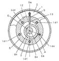
ここで、クランク軸中心6aはシリンダ中心8bとは一致せず、仕切り板9の軸線に対して高圧の圧縮室側に変位されている。つまり、クランク軸中心6aとシリンダ中心8bの中心を結んだ延長線上に位置するAの部位において、ローラ7とシリンダ内径8aの隙間Sが他の部分の隙間Sに対して最小となるよう組み立てられている(以下最小隙間はSminと称す)。最小隙間位置Aはクランク軸の回転方向に対して180°〜270°の範囲の中に設けられている(ここで、クランク軸の偏心部が仕切り板の軸線方向に一致する位置、すなわちクランク軸の偏心が最大である位置が仕切り板106に接している状態の位置を0°とする)。一方、主端板10や補助端板11はシリンダ8に設けられたネジ部14に複数(本実施例では5本)のボルト15を用いて締結されている。そこでこれらのうち最小隙間位置A付近を締結するねじ部14aの締結力を他の箇所のねじ部14bの締結力より小さくして組み立てられている。
【0018】
ボルト15aの締結力はシリンダの材質、厚み寸法などに応じて決められ、主端板10と補助端板11とによりシリンダ8が十分に締め付け固定される締結力であること、締結によりローラ7がシリンダ内径8aと干渉しない締結力であることは勿論、締結によるシリンダ内径8aの歪みを最小にするか、または隙間が圧縮効率の低下に影響を与えない程度の予め設計されたSminになるように決定されるとよい。
【0019】
上記の構成によって、圧縮機の効率に大きく影響する最小隙間Sminに対してその付近のボルト15の締結による歪みを減少することが出来るため最小隙間Sminを更に小さく設定してもローラ7とシリンダ内径8aが干渉することがないため高効率で信頼性の高い圧縮機を提供することができる。
【0020】
(実施例2)
図5は主端板10や補助端板11はシリンダ8に設けられたネジ部14に数本のボルト15によって締結されており、このボルト15の中でローラ7と隙間が最小となる位置付近を締結するボルトのねじの呼び径は他の箇所のボルトのねじの呼び径より小さくして組み立てられている。例えば、最小隙間位置付近の15eのボルト及びねじのみM4の呼び径のものを用いて100kg・cmのトルクで締め付け、その他の4本のボルト15fを通常のM6の呼び径のものを用いて150kg・cmのトルクで締め付ける。
【0021】
上記の構成によって、圧縮機の効率に大きく影響する最小隙間Sminに対してその付近のシリンダ内径8aとネジ部14の最小肉厚が大きくなることでボルト15の締結による歪みを減少することが出来るため最小隙間Sminを更に小さく設定してもローラ7とシリンダ内径8aが干渉することが無くなり高効率で信頼性の高い圧縮機を提供することができる。
【0022】
なお、シリンダ内径8aからねじ部までの距離を確保するために、最小隙間位置付近のねじのみ、他の位置のねじよりもシリンダ内径から遠い位置に配設するようにすれば、ねじの呼び径を小さくすることによる締結力の低下を招くことなく、しかも最小隙間位置での締結による歪みをより小さくすることができる。
【0023】
また、ローラとシリンダ内径の隙間が最小となる位置を、仕切り板の軸線に対して高圧の圧縮室側、すなわち、仕切り板9の中心線9aよりも吐出口を有する側に設けることが圧縮効率向上の点で好ましい。さらには、実施例1に示した範囲に設定するのが更に好ましい。
【0024】
【発明の効果】
上記実施例から明らかなように、本願発明は、密閉容器内に電動機と、この電動機によって駆動されるクランク軸と、クランク軸にて駆動されるローラと、このローラを収納するシリンダと、このシリンダとローラに当接しシリンダ内を仕切る仕切板と、シリンダの両端面を数本のボルトにて締結され閉塞するとともにクランク軸を保持する軸受けを兼ねる主端板と補助端板とを有し、これら締結ボルトのうちローラとシリンダ内径の隙間が最小となる位置付近を締結するボルトの締結力を他の箇所のボルトの締結力より小さくしたもので、この構成によれば圧縮機の効率に大きく影響する最小隙間Sminに対してその付近のボルト15の締結による歪みを減少することができるため最小隙間Sminを更に小さく設定してもローラ7とシリンダ内径8aが干渉することがないため高効率で信頼性の高い圧縮機を提供することができるものである。
【0025】
また、本願発明は、締結ボルトのうちローラとシリンダ内径の隙間が最小となる位置付近を締結するボルトのねじの呼び径を他の箇所のボルトのねじの呼び径より小さくしたもので、この構成によれば圧縮機の効率に大きく影響する最小隙間Sminに対してその付近のボルト15の締結による歪みを減少することができるため最小隙間Sminを更に小さく設定してもローラ7とシリンダ内径8aが干渉することがないため高効率で信頼性の高い圧縮機を提供することができるものである。
【0026】
また、本願発明は、は最小隙間位置付近のボルトのみ、ねじの位置を他のボルトに対するねじ位置よりもシリンダ内径から遠い位置に配置したものである。これにより、同じ呼び径のねじを用いて、同じトルクで締め付けるとしても、最小隙間位置付近のボルトはシリンダ内径からより遠い位置に配置されているため、締め付けによるシリンダの歪みはより多方向に分散され、最小隙間位置での締結による歪みをより小さくすることができる。
【図面の簡単な説明】
【図1】 本発明の実施例を示す圧縮機の縦断面図
【図2】 主端板側からみた圧縮機構部の締結状態の概要を示す平面図
【図3】 本発明の第一の実施例の圧縮機構部の構成概要を示す横断面図
【図4】 第3図のローラの回転位置違いの状態を示す横断面図
【図5】 本発明の第二の実施例の圧縮機構部の構成概要を示す横断面図
【図6】 従来の圧縮機の縦断面図
【図7】 第6図の圧縮機構部の構成概要を示す平面図
【符号の説明】
1 密閉容器
3 電動機
6 クランク軸
7 ローラ
8 シリンダ
9 仕切板
10 主端板
11 補助端板
15 ボルト[0001]
BACKGROUND OF THE INVENTION
The present invention relates to an improvement in compression efficiency of a hermetic compressor.
[0002]
[Prior art]
In a conventional rotary type compressor, as shown in FIGS. 6 to 7 , an
[0003]
On the other hand, the
[0004]
However, when the
[0005]
[Problems to be solved by the invention]
In the conventional compressor described above, the gas during the compression stroke leaks into the suction stroke through the gap, which is a cause of a decrease in compression efficiency.
[0006]
On the other hand, if the minimum gap is designed to be small in order to improve the compression efficiency, the
[0007]
In view of the above problems, the present invention can provide a highly efficient hermetic compressor by designing the minimum gap to be smaller by reducing the influence of local distortion of the cylinder inner diameter in the vicinity of the minimum gap due to bolt fastening. It is something that can be done.
[0008]
[Means for Solving the Problems]
In order to solve the above problems, the present invention makes at least one bolt fastening force near the minimum gap position smaller than bolt fastening forces at other locations.
[0009]
In another invention of the present application, the nominal diameter of the screw of the bolt near the minimum gap position is made smaller than the nominal diameter of the screw of the bolt at another location.
[0010]
In another invention of the present application, only the bolt in the vicinity of the minimum gap position is arranged such that the screw position is farther from the cylinder inner diameter than the screw position with respect to the other bolts.
[0011]
DETAILED DESCRIPTION OF THE INVENTION
In the present invention, at least one bolt fastening force in the vicinity of the minimum gap position is made smaller than bolt fastening forces at other locations. Thereby, even if the gap size is made smaller at the beginning, interference between the cylinder inner diameter and the roller can be prevented, and the amount of gas in the compression stroke leaking into the suction stroke through the gap between the roller and the cylinder inner diameter is reduced. It is possible to improve the compression efficiency during the operation of the compressor.
[0012]
Moreover, the nominal diameter of the screw of the bolt in the vicinity of the minimum gap is made smaller than the nominal diameter of the screw of the bolt in other places. Thereby, even if the gap size is initially reduced, interference between the cylinder inner diameter and the roller can be prevented, and the amount of gas in the compression stroke leaking into the suction stroke through the gap can be reduced.
[0013]
In another invention of the present application, only the bolt in the vicinity of the minimum gap position is arranged such that the screw position is farther from the cylinder inner diameter than the screw position with respect to the other bolts. As a result, even if the same nominal diameter screws are used and tightened with the same torque, the bolts near the minimum clearance position are located farther from the cylinder inner diameter, so the cylinder distortion due to tightening is distributed in more directions. Thus, distortion due to fastening at the minimum gap position can be further reduced.
[0014]
【Example】
Embodiments of the present invention will be described below with reference to the drawings.
[0015]
Example 1
As shown in FIGS. 1 to 4, in the rotary type hermetic compressor, the
[0016]
The
[0017]
Here, the
[0018]
The fastening force of the bolt 15a is determined according to the material and thickness of the cylinder, and the fastening force is such that the
[0019]
With the above configuration, distortion due to fastening of the
[0020]
(Example 2 )
In FIG. 5, the
[0021]
With the above configuration, distortion due to fastening of the
[0022]
In order to secure the distance from the cylinder
[0023]
Further, the compression efficiency is such that the position where the gap between the roller and the cylinder inner diameter is minimum is provided on the side of the compression chamber having a high pressure with respect to the axis of the partition plate, that is, on the side having the discharge port from the
[0024]
【The invention's effect】
As is apparent from the above embodiments, the present invention includes an electric motor in a sealed container, a crankshaft driven by the electric motor, a roller driven by the crankshaft, a cylinder for storing the roller, and the cylinder A partition plate that comes into contact with the roller and partitions the inside of the cylinder, and a main end plate and an auxiliary end plate that serve as bearings for fastening and closing the both end surfaces of the cylinder with several bolts and holding the crankshaft. Among the fastening bolts, the fastening force of the bolts that fasten the vicinity of the position where the gap between the roller and the cylinder inner diameter is minimum is made smaller than the fastening force of the bolts at other locations, and this configuration greatly affects the efficiency of the compressor. Therefore, even if the minimum clearance Smin is set to be smaller, the
[0025]
Further, the present invention has a configuration in which the nominal diameter of the screw of the bolt that fastens the vicinity of the position where the gap between the roller and the cylinder inner diameter becomes the smallest among the fastening bolts is smaller than the nominal diameter of the screw of the bolt in other places. According to the above, since the distortion due to the fastening of the
[0026]
In the present invention, only the bolts near the minimum gap position are arranged such that the screw positions are farther from the cylinder inner diameter than the screw positions for the other bolts. As a result, even if the same nominal diameter screws are used and tightened with the same torque, the bolts near the minimum clearance position are located farther from the cylinder inner diameter, so the cylinder distortion due to tightening is distributed in more directions. Thus, distortion due to fastening at the minimum gap position can be further reduced.
[Brief description of the drawings]
FIG. 1 is a longitudinal sectional view of a compressor showing an embodiment of the present invention. FIG. 2 is a plan view showing an outline of a fastening state of a compression mechanism section viewed from the main end plate side. FIG. 4 is a cross-sectional view showing an outline of the configuration of the compression mechanism portion of the example. FIG. 4 is a cross-sectional view showing a state of the rotational position difference of the roller of FIG. Cross-sectional view showing the configuration outline
FIG. 6 is a longitudinal sectional view of a conventional compressor
7 is a plan view showing a schematic configuration of a compression mechanism portion of FIG. 6 [Description of symbols]
DESCRIPTION OF
Claims (5)
Priority Applications (1)
| Application Number | Priority Date | Filing Date | Title |
|---|---|---|---|
| JP2000288355A JP4019620B2 (en) | 2000-09-22 | 2000-09-22 | Hermetic compressor |
Applications Claiming Priority (1)
| Application Number | Priority Date | Filing Date | Title |
|---|---|---|---|
| JP2000288355A JP4019620B2 (en) | 2000-09-22 | 2000-09-22 | Hermetic compressor |
Publications (2)
| Publication Number | Publication Date |
|---|---|
| JP2002098075A JP2002098075A (en) | 2002-04-05 |
| JP4019620B2 true JP4019620B2 (en) | 2007-12-12 |
Family
ID=18771949
Family Applications (1)
| Application Number | Title | Priority Date | Filing Date |
|---|---|---|---|
| JP2000288355A Expired - Fee Related JP4019620B2 (en) | 2000-09-22 | 2000-09-22 | Hermetic compressor |
Country Status (1)
| Country | Link |
|---|---|
| JP (1) | JP4019620B2 (en) |
Families Citing this family (4)
| Publication number | Priority date | Publication date | Assignee | Title |
|---|---|---|---|---|
| JP5033391B2 (en) * | 2006-10-20 | 2012-09-26 | 日立アプライアンス株式会社 | Rotary compressor |
| JP2009281305A (en) * | 2008-05-23 | 2009-12-03 | Daikin Ind Ltd | Compressor |
| JP2013092134A (en) * | 2011-10-27 | 2013-05-16 | Mitsubishi Electric Corp | Rotary compressor |
| WO2013179677A1 (en) * | 2012-06-01 | 2013-12-05 | パナソニック株式会社 | Rotary compressor |
-
2000
- 2000-09-22 JP JP2000288355A patent/JP4019620B2/en not_active Expired - Fee Related
Also Published As
| Publication number | Publication date |
|---|---|
| JP2002098075A (en) | 2002-04-05 |
Similar Documents
| Publication | Publication Date | Title |
|---|---|---|
| CN1045486C (en) | Sealed electric compressor with two cylinders and method for assembly of same | |
| US6336799B1 (en) | Multi-cylinder rotary compressor | |
| EP3926171B1 (en) | Scroll compressor, vehicle air conditioner and vehicle | |
| JPS63205486A (en) | Two-cylinder rotary compressor | |
| US20190093649A1 (en) | Reciprocating type compressor | |
| JP4019620B2 (en) | Hermetic compressor | |
| JP2000087889A (en) | Rotary compressor | |
| JP3319026B2 (en) | Rotary compressor | |
| KR101115260B1 (en) | Connection member and rotary compressor | |
| JP2000220590A (en) | Rotary compressor | |
| KR20030037834A (en) | Bearing plate structure for compressor | |
| JP2633336B2 (en) | Horizontal rotary compressor | |
| WO2020166430A1 (en) | Compressor | |
| JPH0133831Y2 (en) | ||
| JPH041356Y2 (en) | ||
| JP2008057394A (en) | Rotary compressor and refrigeration cycle apparatus | |
| JP2009047017A (en) | Compressor | |
| JPH08200262A (en) | Closed type rotary compressor | |
| JPH10169585A (en) | Rotary compressor | |
| KR20010046225A (en) | Discharge valve assembly for rotary compressor | |
| JPH07103166A (en) | Multi-cylinder type rotary compressor | |
| KR100202881B1 (en) | Hermetic Compressor Stator Assembly Fixture | |
| JPS62243984A (en) | Rotary compressor | |
| JP2003336584A (en) | Scroll compressor | |
| JP2006233883A (en) | Method for manufacturing hermetic type rotary compressor |
Legal Events
| Date | Code | Title | Description |
|---|---|---|---|
| A621 | Written request for application examination |
Free format text: JAPANESE INTERMEDIATE CODE: A621 Effective date: 20050411 |
|
| RD01 | Notification of change of attorney |
Free format text: JAPANESE INTERMEDIATE CODE: A7421 Effective date: 20050630 |
|
| A131 | Notification of reasons for refusal |
Free format text: JAPANESE INTERMEDIATE CODE: A131 Effective date: 20070327 |
|
| A977 | Report on retrieval |
Free format text: JAPANESE INTERMEDIATE CODE: A971007 Effective date: 20070330 |
|
| A521 | Written amendment |
Free format text: JAPANESE INTERMEDIATE CODE: A523 Effective date: 20070516 |
|
| A131 | Notification of reasons for refusal |
Free format text: JAPANESE INTERMEDIATE CODE: A131 Effective date: 20070619 |
|
| A521 | Written amendment |
Free format text: JAPANESE INTERMEDIATE CODE: A523 Effective date: 20070808 |
|
| TRDD | Decision of grant or rejection written | ||
| A01 | Written decision to grant a patent or to grant a registration (utility model) |
Free format text: JAPANESE INTERMEDIATE CODE: A01 Effective date: 20070904 |
|
| A61 | First payment of annual fees (during grant procedure) |
Free format text: JAPANESE INTERMEDIATE CODE: A61 Effective date: 20070917 |
|
| FPAY | Renewal fee payment (event date is renewal date of database) |
Free format text: PAYMENT UNTIL: 20101005 Year of fee payment: 3 |
|
| R151 | Written notification of patent or utility model registration |
Ref document number: 4019620 Country of ref document: JP Free format text: JAPANESE INTERMEDIATE CODE: R151 |
|
| FPAY | Renewal fee payment (event date is renewal date of database) |
Free format text: PAYMENT UNTIL: 20101005 Year of fee payment: 3 |
|
| FPAY | Renewal fee payment (event date is renewal date of database) |
Free format text: PAYMENT UNTIL: 20111005 Year of fee payment: 4 |
|
| FPAY | Renewal fee payment (event date is renewal date of database) |
Free format text: PAYMENT UNTIL: 20121005 Year of fee payment: 5 |
|
| FPAY | Renewal fee payment (event date is renewal date of database) |
Free format text: PAYMENT UNTIL: 20131005 Year of fee payment: 6 |
|
| LAPS | Cancellation because of no payment of annual fees |