JP4008629B2 - Semiconductor device, design method thereof, and computer-readable recording medium storing the design program - Google Patents
Semiconductor device, design method thereof, and computer-readable recording medium storing the design program Download PDFInfo
- Publication number
- JP4008629B2 JP4008629B2 JP25797999A JP25797999A JP4008629B2 JP 4008629 B2 JP4008629 B2 JP 4008629B2 JP 25797999 A JP25797999 A JP 25797999A JP 25797999 A JP25797999 A JP 25797999A JP 4008629 B2 JP4008629 B2 JP 4008629B2
- Authority
- JP
- Japan
- Prior art keywords
- wiring
- layer
- via contact
- main
- main wiring
- Prior art date
- Legal status (The legal status is an assumption and is not a legal conclusion. Google has not performed a legal analysis and makes no representation as to the accuracy of the status listed.)
- Expired - Fee Related
Links
- 239000004065 semiconductor Substances 0.000 title claims description 57
- 238000000034 method Methods 0.000 title claims description 32
- 239000002184 metal Substances 0.000 claims description 73
- 239000010410 layer Substances 0.000 description 331
- 238000004519 manufacturing process Methods 0.000 description 9
- 230000003287 optical effect Effects 0.000 description 4
- 230000010354 integration Effects 0.000 description 3
- 230000008054 signal transmission Effects 0.000 description 3
- 235000004522 Pentaglottis sempervirens Nutrition 0.000 description 2
- 239000004020 conductor Substances 0.000 description 2
- 230000000694 effects Effects 0.000 description 2
- 239000011229 interlayer Substances 0.000 description 2
- 238000001459 lithography Methods 0.000 description 2
- 239000000463 material Substances 0.000 description 2
- 239000000758 substrate Substances 0.000 description 2
- 240000004050 Pentaglottis sempervirens Species 0.000 description 1
- 239000000470 constituent Substances 0.000 description 1
- 230000007423 decrease Effects 0.000 description 1
- 230000007547 defect Effects 0.000 description 1
- 238000010586 diagram Methods 0.000 description 1
- 238000004904 shortening Methods 0.000 description 1
Images


Classifications
-
- H—ELECTRICITY
- H01—ELECTRIC ELEMENTS
- H01L—SEMICONDUCTOR DEVICES NOT COVERED BY CLASS H10
- H01L21/00—Processes or apparatus adapted for the manufacture or treatment of semiconductor or solid state devices or of parts thereof
- H01L21/70—Manufacture or treatment of devices consisting of a plurality of solid state components formed in or on a common substrate or of parts thereof; Manufacture of integrated circuit devices or of parts thereof
- H01L21/71—Manufacture of specific parts of devices defined in group H01L21/70
- H01L21/768—Applying interconnections to be used for carrying current between separate components within a device comprising conductors and dielectrics
-
- H—ELECTRICITY
- H01—ELECTRIC ELEMENTS
- H01L—SEMICONDUCTOR DEVICES NOT COVERED BY CLASS H10
- H01L23/00—Details of semiconductor or other solid state devices
- H01L23/52—Arrangements for conducting electric current within the device in operation from one component to another, i.e. interconnections, e.g. wires, lead frames
- H01L23/522—Arrangements for conducting electric current within the device in operation from one component to another, i.e. interconnections, e.g. wires, lead frames including external interconnections consisting of a multilayer structure of conductive and insulating layers inseparably formed on the semiconductor body
- H01L23/5226—Via connections in a multilevel interconnection structure
-
- G—PHYSICS
- G06—COMPUTING; CALCULATING OR COUNTING
- G06F—ELECTRIC DIGITAL DATA PROCESSING
- G06F30/00—Computer-aided design [CAD]
- G06F30/30—Circuit design
- G06F30/39—Circuit design at the physical level
- G06F30/394—Routing
-
- H—ELECTRICITY
- H01—ELECTRIC ELEMENTS
- H01L—SEMICONDUCTOR DEVICES NOT COVERED BY CLASS H10
- H01L23/00—Details of semiconductor or other solid state devices
- H01L23/52—Arrangements for conducting electric current within the device in operation from one component to another, i.e. interconnections, e.g. wires, lead frames
- H01L23/522—Arrangements for conducting electric current within the device in operation from one component to another, i.e. interconnections, e.g. wires, lead frames including external interconnections consisting of a multilayer structure of conductive and insulating layers inseparably formed on the semiconductor body
- H01L23/528—Layout of the interconnection structure
-
- H—ELECTRICITY
- H01—ELECTRIC ELEMENTS
- H01L—SEMICONDUCTOR DEVICES NOT COVERED BY CLASS H10
- H01L2924/00—Indexing scheme for arrangements or methods for connecting or disconnecting semiconductor or solid-state bodies as covered by H01L24/00
- H01L2924/0001—Technical content checked by a classifier
- H01L2924/0002—Not covered by any one of groups H01L24/00, H01L24/00 and H01L2224/00
Landscapes
- Engineering & Computer Science (AREA)
- Physics & Mathematics (AREA)
- Computer Hardware Design (AREA)
- General Physics & Mathematics (AREA)
- Condensed Matter Physics & Semiconductors (AREA)
- Power Engineering (AREA)
- Microelectronics & Electronic Packaging (AREA)
- Geometry (AREA)
- Theoretical Computer Science (AREA)
- Evolutionary Computation (AREA)
- General Engineering & Computer Science (AREA)
- Computer Networks & Wireless Communication (AREA)
- Manufacturing & Machinery (AREA)
- Design And Manufacture Of Integrated Circuits (AREA)
- Preparing Plates And Mask In Photomechanical Process (AREA)
- Internal Circuitry In Semiconductor Integrated Circuit Devices (AREA)
Description
【0001】
【発明の属する技術分野】
本発明は半導体装置、その設計方法、及びその設計プログラムを格納したコンピュータ読み取り可能な記録媒体に係わり、特に、多層配線構造を有する半導体装置に関わる。さらに特に、配線層間を接続するヴィアコンタクトにカバレッジ配線を含ませることにより、金属配線の微細化及び集積度の向上を図った半導体装置の設計方法に関する。
【0002】
【従来の技術】
近年、半導体集積回路において、微細加工技術は急速に進歩しており、半導体集積回路のパターン寸法が縮小されている。しかし、このパターン寸法の縮小により、パターン形状に現れる弊害要素が顕在化するようになってきている。
【0003】
例えば、金属配線の微細化においては、マスクの精度を上げたとしても、リソグラフィ工程において、光近接効果により金属配線の終端で丸めが生じる。この丸めが生じた金属配線の終端において異なる配線層とヴィアコンタクトを介して接続する場合、ヴィアコンタクトとの接続面積が減ってしまうか、無くなってしまうために、金属配線とヴィアコンタクトとの接触抵抗が増大するか、信号線となる金属配線のオープン不良の可能性が出てくる。
【0004】
図11は、従来技術に係わる金属配線の設計パターンを示す平面図である。上層の金属配線(53、54)の終端でヴィアコンタクト(51、52)を介して下層の金属配線(55、56)と接続されている。図12は、図1の設計図に従って製造された金属配線を示す平面図である。図13は、図12の設計グリッドV2に沿った断面図である。設計グリッドは、各層の金属配線同士が隣り合うことのできる最小の間隔を示す。図12に示すように、金属配線(53、54)の製造工程(リソグラフィ工程)において、金属配線(53、54)の終端で丸めが生じてしまう。そして図13に示すように、矢印に示す方向に金属配線(53、54)の終端が移動していき、ヴィアコンタクト(51、52)との接続面積が減少していく。図13中における点線は設計図面上での配線の終端を示している。
【0005】
そこで一般に、金属配線とヴィアコンタクトとの接続面積を増やすために、OPC(Optical Proximity Correction)と呼ばれる、マスク描画データの作成段階でデータ補正を金属配線の終端に入れる方法が用いられる。その一つの方法としてヴィアコンタクトに対して全方向に金属配線のカバレッジを増やす補助パターンを付与する方法がある。図14は、ヴィアコンタクトに対して金属配線のカバレッジを全方向に入れた補正パターン(58、59)を付与した設計パターンを示す。図3に示す設計パターンに従って金属配線を形成することで、金属配線の終端の丸めが解消され、ヴィアコンタクトとの接続面積を増やすことができる。
【0006】
【課題が解決しようとする課題】
しかし、図14に示す補正パターン(58、59)を付与する方法では、ヴィアコンタクト(51、52)があるところの上下の配線層の両方の金属配線の終端部が、全方向に対して広くなる。したがって、図14に示すように、ヴィアコンタクト(51、52)を設計グリッドH2を空けて配置する必要が生じる。また、ヴィアコンタクト(51、52)に隣接する設計グリッド上に他の金属配線及び他のヴィアコンタクトを配置することもできなくなる。もしくは、設計グリッドの間隔を補正パターン(58、59)の分だけ広げることで上記問題点は解決する。しかし、いづれにしても補正パターン(58、59)により金属配線の集積度は落ちてしまう。
【0007】
また、補正パターンを付与することで、設計パターンのデータ量が増加するため、マスク描画データの作製で時間がかかり、半導体集積回路の開発期間の短縮に大きな障害となっている。
【0008】
本発明は上記問題点を解決するために成されたものであり、本発明の目的は、金属配線とヴィアコンタクトの接触不良が少なく、且つ、集積度の高い半導体装置及びその設計方法を提供することである。
【0009】
本発明の他の目的は、開発期間を短くした半導体装置及びその設計方法を提供することである。
【0010】
【課題を解決するための手段】
上記目的を達成するため、本発明の態様によれば、ヴィアコンタクトと、終端においてヴィアコンタクトを介して接続されたN配線層及びN+1配線層の主配線とを有する半導体装置において、主配線のそれぞれの配線方向に対して垂直な方向にのみ主配線の終端に続けてヴィアコンタクトから張り出して配置された、線幅が主配線と同じあるいは主配線より狭いカバレッジ配線をさらに有する半導体装置が提供される。
【0011】
ここで、「ヴィアコンタクト」は、半導体装置の多層配線構造において、上下に隣接する金属配線層間を電気的に接続するために層間膜中に形成された導体プラグである。ヴィアコンタクトの平面形状は問わない。方形状、円形状あるいはその他の平面形状であっても構わない。また、「主配線」は、半導体装置においてチップ上の機能ブロックあるいは素子間を電気的に接続し、信号の伝達のために機能する金属配線である。さらに、「カバレッジ配線」は、「主配線」の終端に続けて配置されているので主配線に電気的に接続されているが、信号伝達の機能は有していない金属配線である。カバレッジ配線は、構成材料、製造方法、及び製造工程が主配線と同じであることが望ましい。カバレッジ配線は、ヴィアコンタクトの周辺のうち、主配線の配線方向に平行な方向にのみ配置されており、従来のようにヴィアコンタクト周辺全体にわたってカバレッジされた補正パターンとは異なるものである。また、カバレッジ配線の平面形状は問わない。方形状、円形状あるいはその他の形状であっても構わない。
【0014】
本発明の態様によれば、主配線の配線方向に対して垂直な方向にのみ配線の終端に続けて配置された、線幅が主配線と同じあるいは狭いカバレッジ配線を設けることで、金属配線の終端において丸めが発生しても、その丸めはカバレッジ配線で発生し、主配線の終端においては発生を抑えることができるため、ヴィアコンタクトと主配線との接触不良あるいはオープン不良を防ぐことができる。
【0015】
本発明の他の態様によれば、N+1配線層とN配線層の主配線と、N+1配線層とN配線層間を電気的に接続するN層ヴィアコンタクトのパターン情報を作成するステップと、自動配置ツールを用いて、機能ブロックあるいは素子をチップ上に配置するステップと、自動配線ツール及びパターン情報を用いて、N+1配線層とN配線層の主配線と、N層ヴィアコンタクトを配置して、機能ブロックあるいは素子間を接続する金属配線を形成するステップとを有するX層配線構造からなる半導体装置の設計方法において、N層ヴィアコンタクトのパターン情報が、N層ヴィアコンタクトの上及びN+1配線層の配線方向に対して0度方向及び180度方向にのみN層ヴィアコンタクトから張り出して配置された、線幅が主配線と同じあるいは主配線よりも狭いN+1層カバレッジ領域と、N層ヴィアコンタクト下及びN配線層の配線方向に対して0度方向及び180度方向にのみN層ヴィアコンタクトから張り出して配置された、線幅が主配線と同じあるいは主配線よりも狭いN層カバレッジ領域とを含む半導体装置の設計方法が提供される。
【0016】
ここで、「N」は、X層多層配線構造を有する半導体装置において、0≦N≦X−1の条件を満たす任意の自然数である。ただし、N=0の場合、N配線層は基板を示し、N+1配線層は第1の配線層を示す。
【0017】
本発明の他の態様によれば、主配線の配線方向に対して0度及び180度方向にのみ配線の終端に続けて配置された、線幅が主配線と同じあるいは狭いカバレッジ領域をヴィアコンタクトに含ませることで、自動配線ツールにより形成された金属配線において、主配線が終端においてヴィアコンタクトと接続する場合に、金属配線の終端において丸めが発生しても、その丸めはカバレッジ配線で発生し、主配線の終端においては発生を抑えることができる。したがって、ヴィアコンタクトと主配線との接触不良あるいはオープン不良を防ぐことができる。また、ヴィアコンタクト周辺において主配線の線幅の広がりを抑えることができるため、ヴィアコンタクトに隣接する設計グリッドあるいはグリッド点上に、他の主配線あるいは他のヴィアコンタクトをデザインルールに違反することなく、配置することができる。したがって、金属配線及びヴィアコンタクトを高密度に配置することができ、集積度の高い金属配線のレイアウトを行うことができる。また、金属配線のレイアウト作業において、自動配線ツールにかけるヴィアコンタクトの情報に、カバレッジ領域を予め含ませることにより、マスク描画データの作成時にカバレッジ領域を補正パターンとして主配線に付与することがないので、設計パターンのデータ量が増加することなく、マスク描画データの作製で時間を短縮し、半導体装置の開発期間を短縮することができる。
【0018】
本発明の他の態様によれば、N+1配線層とN配線層の主配線と、N+1配線層とN配線層間を電気的に接続するN層ヴィアコンタクトのパターン情報を作成するステップと、自動配置ツールを用いて、機能ブロックあるいは素子をチップ上に配置するステップと、自動配線ツール及びパターン情報を用いて、N+1配線層とN配線層の主配線と、N層ヴィアコンタクトを配置して、機能ブロックあるいは素子間を接続する金属配線を形成するステップとを有するX層配線構造からなる半導体装置の設計方法において、N層ヴィアコンタクトのパターン情報が、N層ヴィアコンタクトの上及びN+1配線層の配線方向に対して90度方向及び270度方向にのみN層ヴィアコンタクトから張り出して配置された、線幅が主配線と同じあるいは主配線よりも狭いN+1層カバレッジ領域と、N層ヴィアコンタクト下及びN配線層の配線方向に対して90度方向及び270度方向にのみN層ヴィアコンタクトから張り出して配置された、線幅が主配線と同じあるいは主配線よりも狭いN層カバレッジ領域とを含む半導体装置の設計方法が提供される。
【0019】
本発明の他の態様によれば、主配線の配線方向に対して90度及び270度方向にのみ配線の終端に続けて配置された、線幅が主配線と同じあるいは狭いカバレッジ領域をヴィアコンタクトに含ませることで、自動配線ツールにより形成された金属配線において、主配線が終端においてヴィアコンタクトと接続する場合に、金属配線の終端において丸めが発生しても、その丸めはカバレッジ配線で発生し、主配線の終端においては発生を抑えることができる。したがって、ヴィアコンタクトと主配線との接触不良あるいはオープン不良を防ぐことができる。また、金属配線のレイアウト作業において、自動配線ツールにかけるヴィアコンタクトの情報に、カバレッジ領域を予め含ませることにより、マスク描画データの作成時にカバレッジ領域を補正パターンとして主配線に付与することがないので、設計パターンのデータ量が増加することなく、マスク描画データの作製で時間を短縮し、半導体装置の開発期間を短縮することができる。
【0020】
本発明の他の態様によれば、N+1配線層とN配線層の主配線と、N+1配線層とN配線層間を電気的に接続するN層ヴィアコンタクトのパターン情報を作成するステップと、自動配置ツールを用いて、機能ブロックあるいは素子をチップ上に配置するステップと、自動配線ツール及びパターン情報を用いて、N+1配線層とN配線層の主配線と、N層ヴィアコンタクトを配置して、機能ブロックあるいは素子間を接続する金属配線を形成するステップとを有するX層配線構造からなる半導体装置の設計プログラムにおいて、N層ヴィアコンタクトのパターン情報が、N層ヴィアコンタクトの上及びN+1配線層の配線方向に対して0度方向及び180度方向にのみN層ヴィアコンタクトから張り出して配置された、線幅が主配線と同じあるいは主配線よりも狭いN+1層カバレッジ領域と、N層ヴィアコンタクト下及びN配線層の配線方向に対して0度方向及び180度方向にのみN層ヴィアコンタクトから張り出して配置された、線幅が主配線と同じあるいは主配線よりも狭いN層カバレッジ領域とを含む半導体装置の設計プログラムを格納したコンピュータ読み取り可能な記録媒体が提供される。
【0021】
本発明の他の態様によれば、N+1配線層とN配線層の主配線と、N+1配線層とN配線層間を電気的に接続するN層ヴィアコンタクトのパターン情報を作成するステップと、自動配置ツールを用いて、機能ブロックあるいは素子をチップ上に配置するステップと、自動配線ツールを用いて、N+1配線層とN配線層の主配線と、N層ヴィアコンタクトを配置して、機能ブロックあるいは素子間を接続する金属配線を形成するステップとを有するX層配線構造からなる半導体装置の設計プログラムにおいて、N層ヴィアコンタクトのパターン情報が、N層ヴィアコンタクトの上及びN+1配線層の配線方向に対して90度方向及び270度方向にのみN層ヴィアコンタクトから張り出して配置された、線幅が主配線と同じあるいは主配線よりも狭いN+1層カバレッジ領域と、N層ヴィアコンタクト下及びN配線層の配線方向に対して90度方向及び270度方向にのみN層ヴィアコンタクトから張り出して配置された、線幅が主配線と同じあるいは主配線よりも狭いN層カバレッジ領域とを含む半導体装置の設計プログラムを格納したコンピュータ読み取り可能な記録媒体が提供される。
【0022】
【発明の実施の形態】
以下、図面を参照して本発明の実施の形態について説明する。図面の記載において従来技術と類似な部分には類似な符号を付している。図1は、本発明の第1の実施の形態に係わる半導体装置の金属配線を示す。
【0023】
(第1の実施の形態)
図1に示すように、本発明の第1の実施の形態に係わる半導体装置は、ヴィアコンタクト(1、2)と、終端においてヴィアコンタクト(1、2)に接続する主配線(3〜6)とを有する半導体装置において、主配線(3〜6)の配線方向に対して平行な方向にのみ主配線(3〜6)の終端に続けてヴィアコンタクト(1、2)から張り出して配置された、線幅が主配線(3〜6)と同じあるいは主配線(3〜6)より狭いカバレッジ配線(7〜10)を有している。
【0024】
ヴィアコンタクト(1、2)は、半導体装置の多層配線構造において、上下に隣接する金属配線層間を電気的に接続するために層間膜中に形成された導体プラグである。図1に示すように、第1の実施の形態においてヴィアコンタクトは、第1のヴィアコンタクト1と、第2のヴィアコンタクト2からなる。第1及び第2のヴィアコンタクト(1、2)は、設計グリッド上に配置されている。設計グリッドは、各層の金属配線同士が隣り合うことのできる最小の間隔を示し、図1では、垂直方向の設計グリッド(V1〜V4)及び水平方向の設計グリッド(H1〜H4)が格子状に配列されている。垂直方向の設計グリッドと水平方向の設計グリッドの交差する点をグリッド点と定義すると、第1のヴィアコンタクト1は、グリッド点(V2−H3)の上に配置され、第2のヴィアコンタクト2は、グリッド点(V2−H1)の上に配置されている。また、第1の実施の形態においては、第1及び第2のヴィアコンタクトの口径が主配線(3〜6)の線幅と同じである場合について述べるが、本発明はヴィアコンタクトの口径が、主配線の線幅よりも狭い場合についても適用可能である。さらに図面中では、簡略的に方形状の平面形状で記載されているが、円形あるいはその他の平面形状であっても構わない。
【0025】
主配線(3〜6)は、半導体装置においてチップ上の機能ブロックあるいは素子間を電気的に接続し、信号の伝達のために機能する金属配線である。図1に示すように、第1の実施の形態において主配線(3〜6)は、第1のN層ヴィアコンタクト1にN+1配線層において接続する第1のN+1層主配線3と、N配線層において接続する第1のN層主配線5と、第2のN層ヴィアコンタクト2にN+1配線層において接続する第2のN+1層主配線4と、N配線層において接続する第2のN層主配線6とからなる。総ての主配線(3〜6)は終端においてN層ヴィアコンタクト(1、2)に接続されている。また、総ての主配線(3〜6)は設計グリッド上に配置されている。なお、第1の実施の形態において、Nは、X層多層配線構造を有する半導体装置において、0≦N≦X−1の条件を満たす任意の自然数である。ただし、N=0の場合、N配線層は基板を示し、N+1配線層は第1の配線層を示す。また、N配線層とN+1配線層を接続するヴィアコンタクトをN層ヴィアコンタクト(1、2)と定義する。
【0026】
カバレッジ配線(7〜10)は、金属配線の終端に丸めが生じても、その丸めがカバレッジ配線内のみで生じさせるための金属配線である。主配線(3〜6)の終端に続けて配置されているため、主配線(3〜6)に電気的に接続されているが、信号伝達の機能は有していない。また、カバレッジ配線(7〜10)は、構成材料、製造方法、及び製造工程が主配線(3〜6)と同じであることが望ましい。カバレッジ配線(7〜10)は、ヴィアコンタクト(1、2)の周辺のうち、主配線(3〜6)の配線方向に平行な方向にのみ配置されており、従来のようにヴィアコンタクト周辺全体にわたってカバレッジする補正パターンとは異なるものである。また、図1においてカバレッジ配線(7〜10)の平面形状を方形状に記載しているが、この形状に限られるわけではない。円形あるいはその他の形状であっても構わない。
【0027】
また、カバレッジ配線(7〜10)は、図1に示すように、第1の実施の形態において、第1のN+1層主配線3の終端に続けて配置された第1のN+1層カバレッジ配線8と、第2のN+1層主配線4の終端に続けて配置された第2のN+1層カバレッジ配線10と、第1のN層主配線5の終端に続けて配置された第1のN層カバレッジ配線7と、第2のN層主配線6の終端に続けて接続された第2のN層カバレッジ配線9とからなる。図1においては、N層ヴィアコンタクト(1、2)に接続する主配線(3〜6)の終端を総てN層ヴィアコンタクト(1、2)上に配置したが、本発明は、総ての主配線の終端がN層ヴィアコンタクト(1、2)上に配置される場合に限定されるわけではない。図1中の4つの主配線(3〜6)には、主配線の途中にヴィアコンタクトが形成されているものも含まれていても構わない。途中にヴィアコンタクトが形成されている主配線にはカバレッジ配線は配置されない。
【0028】
図2は、図1の設計グリッドV2に沿った断面図である。図2に示すように、第1のN層ヴィアコンタクト1の上に、第1のN+1層主配線3の終端が配置され、第1のN層ヴィアコンタクト1の下に、第1のN層主配線5が配置されている。同様に、第2のN層ヴィアコンタクト2の上に、第2のN+1層主配線4の終端が配置され、第2のN層ヴィアコンタクト2の下に、第2のN層主配線6が配置されている。図2は、N+1配線層の配線方向に沿った切断面であるため、第1のN+1層主配線3の終端に続けて第1のN+1層カバレッジ配線8が第1のN層ヴィアコンタクト1から張り出して配置されている。同様に、第2のN+1層主配線4の終端に続けて第2のN+1層カバレッジ配線10が第2のN層ヴィアコンタクト2から張り出して配置されている。
【0029】
図3(a)は、図1の設計グリッドH3に沿った断面図である。また、図3(b)は、図2のH1グリッドに沿った断面図である。図3(a)及び図3(b)はN配線層の配線方向に沿った断面であるため、第1のN層ヴィアコンタクト1の下に配置された第1のN層主配線5の終端に続けて第1のN層カバレッジ配線7が第1のN層ヴィアコンタクト1から張り出して配置されている。また、第2のN層ヴィアコンタクト2の下に配置された第2のN層主配線6の終端に続けて第2のN層カバレッジ配線9が第2のN層ヴィアコンタクト2から張り出して配置されている。
【0030】
次に、上記の半導体装置の設計方法について説明する。
【0031】
(1)まず、ステップS1において、通常のLSIの自動配置ツールを用いて、LSIを構成する機能ブロックあるいは素子をデザインルールに違反することなく、チップ上にコンパクトに配置する。この時、各機能ブロックなどを電気的に接続する金属配線を配置するための所定の配線スペースが各機能ブロックなどの間に確保されている。
【0032】
(2)次に、ステップS2において、通常の自動配線ツールを用いて、所定の配線スペース上に、N+1配線層及びN配線層の主配線及びN+1配線層とN配線層間を電気的に接続するN層ヴィアコンタクトを配置して、各機能ブロックなどを接続する金属配線、また入力信号及び出力信号を入出力パッドに送るための配線パターンを形成する。
【0033】
ここで、通常のLSIの金属配線は、予め配線方向が各配線層ごとに垂直方向あるいは水平方向のいずれかに決まって配線される。つまり、配線層が決まればその配線層に形成される金属配線の配線方向は自動的に決まることになる。したがって、自動配線ツールを用いて配置するN層ヴィアコンタクトは、N+1配線層とN配線層間を接続するヴィアコンタクトであるため、接続される主配線の配線方向も自動的に決まる。そこで、ステップS2において、N層ヴィアコンタクトに、接続されるN配線層及びN+1配線層の主配線の配線方向に平行な方向にカバレッジ領域を予め含ませておくことにより、図1に示したようなカバレッジ配線を含んだ金属配線を自動配線ツールにより作成することができる。
【0034】
図4は、本発明に係わる半導体装置の設計方法により作成された金属配線の平面パターンを示す。図4に示すように、N+1配線層とN配線層間を接続するN層ヴィアコンタクト(1、2)は、N層ヴィアコンタクト(1、2)上及びN+1配線層の配線方向に対して0度方向及び180度方向にのみN層ヴィアコンタクト(1、2)から張り出して配置された、線幅が主配線(3、4)と同じあるいは主配線(3、4)よりも狭いN+1層カバレッジ領域(12、14)と、N層ヴィアコンタクト(1、2)下及びN配線層の配線方向に対して0度方向及び180度方向にのみN層ヴィアコンタクト(1、2)から張り出して配置された、線幅が主配線(5、6)と同じあるいは主配線(3、4)よりも狭いN層カバレッジ領域(11、13)を含んでいる。
【0035】
第1の実施の形態においては、N層ヴィアコンタクトは、第1のN層ヴィアコンタクト1と、第2のN層ヴィアコンタクト2とからなる。第1のN層ヴィアコンタクト1の上には、第1のN+1層カバレッジ領域12がN+1配線層の配線方向に張り出して配置され、第1のN層ヴィアコンタクト1の下には、第1のN層カバレッジ領域11がN配線層の配線方向に張り出して配置されている。同様に、第2のN層ヴィアコンタクト2の上には、第2のN+1層カバレッジ領域14がN+1配線層の配線方向に張り出して配置され、第2のN層ヴィアコンタクト2の下には、第2のN層カバレッジ領域13がN配線層の配線方向に張り出して配置されている。また、第1のN+1層主配線3及び第1のN層主配線5がその終端において第1のN層ヴィアコンタクト1にそれぞれ接続しており、第2のN+1層主配線4及び第2のN層主配線6がその終端において第2のN層ヴィアコンタクト2にそれぞれ接続している。
【0036】
図5は図4の設計グリッドV2に沿った断面図である。図5に示すように、第1のN層ヴィアコンタクト1の上に第1のN+1層カバレッジ領域12が配置され、第1のN層ヴィアコンタクト1の下に第1のN層カバレッジ領域11が配置されている。同様に、第2のN層ヴィアコンタクト2の上に第2のN+1層カバレッジ領域14が配置され、第2のN層ヴィアコンタクト2の下に第2のN層カバレッジ領域13が配置されている。N+1配線層の配線方向の沿った断面図である図5においては、第1及び第2のN+1層カバレッジ領域(12、14)が第1及び第2のN層ヴィアコンタクト(1、2)の両側に張り出して形成されているが、第1及び第2のN層カバレッジ領域(11、13)は張り出して形成れていない。また、第1のN+1層カバレッジ領域12の右側の張り出した部分は第1のN+1層主配線3と重なり、第2のN+1層カバレッジ領域14の左側の張り出した部分は第2のN+1層主配線4と重なっている。したがって、N+1配線層の配線構造は、結果的に図2に示したものと同じになる。
【0037】
図6(a)は、図4の設計グリッドH3に沿った断面図である。また、図6(b)は、図4のH1グリッドに沿った断面図である。図6(a)に示すように、第1のN層ヴィアコンタクト1の下に第1のN層カバレッジ領域11が配置され、第1のN層ヴィアコンタクト1の上に第1のN+1層カバレッジ領域12が配置されている。また、図6(b)に示すように、第2のN層ヴィアコンタクト2の下に第2のN層カバレッジ領域13が配置され、第2のN層ヴィアコンタクト2の上に第2のN+1層カバレッジ領域14が配置されている。図6(a)及び図6(b)は、N配線層の配線方向に沿った断面図であるため、第1及び第2のN層カバレッジ領域(11、13)は第1及び第2のN層ヴィアコンタクトの両側に張り出して形成されているが、第1の及び第2のN+1層カバレッジ領域(12、14)は張り出して形成されていない。また、第1のN層カバレッジ領域11の左側の張り出した部分は第1のN層主配線と重なり、第2のN層カバレッジ領域13の右側の張り出した部分は第2のN層主配線6と重なっている。したがって、N配線層の配線構造は、結果的に図3(a)及び図3(b)に示したものと同じになる。
【0038】
この半導体装置の設計方法を実行するためのプログラムは、コンピュータ読み取り可能な記録媒体に保存しておいてもよい。この記録媒体をコンピュータシステムによって読み込ませ、このプログラムを実行して、第1の実施の形態に係わる半導体装置の設計方法を実現することもできる。ここで、記録媒体とは、例えば半導体メモリ、磁気ディスク、光ディスク、光磁気ディスク、磁気テープなどのプログラムを記録することが可能な種々の媒体である。
【0039】
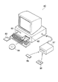
図7は、これらの記録媒体に記録されたプログラムを読み取り、そこに記述された手順に従って、一連の設計方法を実現するコンピュータシステム80の概観を示す鳥瞰図である。コンピュータシステム80の本体前面には、フロッピーディスクドライブ81、およびCD−ROMドライブ82が設けられており、磁気ディスクとしてのフロッピーディスク83、または光ディスクとしてのCD−ROM84を各ドライブ入り口から挿入し、所定の読み出し操作を行うことにより、これらの記録媒体に格納されたプログラムをシステム内にインストールすることができる。また、所定のドライブ装置87を接続することにより、例えばゲームパックなどに使用されている半導体メモリとしてのROM85や、磁気テープとしてのカセットテープ86を用いることもできる。
【0040】
第1の実施の形態によれば、N+1層及びN層カバレッジ配線(7〜10)あるいはN+1層及びN層カバレッジ領域(11〜14)がそれぞれN+1層主配線(3、4)及びN層主配線(5、6)の終端に続いて配置され、N層ヴィアコンタクト(1、2)よりも張り出して形成されているため、金属配線の終端に丸めが生じてもN+1層及びN層カバレッジ領域(11〜14)で丸めが生じるため、N+1層主配線(3、4)及びN層主配線(5、6)の終端で発生する丸めを抑えることができる。
【0041】
また、N+1層カバレッジ配線(8、10)あるいはN+1層カバレッジ領域(12、14)は、設計グリッドH2側に向かってN層ヴィアコンタクト(1、2)より張り出して形成されているため、第1のN層主配線5と第2のN層主配線6は、設計グリッドH2を空けて、設計グリッドH1及び設計グリッドH3の上にそれぞれ配置する必要がある。しかし、第1及び第2のN層主配線(5、6)の線幅は第1及び第2のN層ヴィアコンタクト(1、2)上においても広がりがないため、このグリッドH2には他のN層主配線を通すことができる。同様に設計グリッドH4にも、他の第N層主配線を通すことができる。
【0042】
さらに、第1及び第2のN+1層主配線(3、4)の線幅は第1及び第2のN層ヴィアコンタクト(1、2)上においても広がりがないため、第1及び第2のN+1層主配線(3、4)が配置された設計グリッドV2に隣接する設計グリッド(V1、V3)に、他のN+1層主配線を通すことができる。
【0043】
さらに、カバレッジ配線(7〜10)あるいはカバレッジ領域(11、14)がN層ヴィアコンタクトから張り出して配置されているので、3つのグリッド点(V1−H1、V2−H2、V3−H3)に他のN層ヴィアコンタクトを配置することができない。しかし、ヴィアコンタクトのカバレッジは配線方向のみであるため、N層ヴィアコンタクト(1、2)が配置されたグリッド点(V2−H1、V2−H3)の斜め隣りのグリッド点(V1−H2、V3−H2、V1−H4、V3−H4)に他のヴィアコンタクトを配置することができる。
【0044】
このように、主配線の配線方向に対して平行な方向にのみ配線の終端に続けて配置された、線幅が主配線と同じあるいは狭いカバレッジ配線を設けることで、金属配線の終端において丸めが発生しても、その丸めはカバレッジ配線で発生し、主配線の終端においては発生を抑えることができるため、ヴィアコンタクトと主配線との接触不良あるいはオープン不良を防ぐことができる。また、ヴィアコンタクト周辺において主配線の線幅の広がりを抑えることができるため、ヴィアコンタクトに隣接する設計グリッドあるいはグリッド点上に、他の主配線あるいは他のヴィアコンタクトをデザインルールに違反することなく、配置することができる。したがって、金属配線及びヴィアコンタクトを高密度に配置することができ、集積度の高い金属配線のレイアウトを行うことができる。また、金属配線のレイアウト作業において、自動配線ツールにかけるヴィアコンタクトの情報に、カバレッジ領域を予め含ませることにより、マスク描画データ作成時にカバレッジ領域を補正パターンとして主配線に付与することがないので、設計パターンのデータ量が増加することなく、マスク描画データの作製で時間を短縮し、半導体装置の開発期間を短縮することができる。
【0045】
(第2の実施の形態)
本発明の第1の実施に形態においては、カバレッジ配線あるいはカバレッジ領域は主配線の配線方向に対して平行な方向にのみ配置した場合について述べたが、主配線の配線方向に対して垂直な方向にのみカバレッジを配置しても構わない。図8は本発明の第2の実施の形態に係わる半導体装置の金属配線を示す平面図である。
【0046】
図8に示すように、本発明の第2の実施の形態に係わる半導体装置は、ヴィアコンタクト(1、2)と、終端においてヴィアコンタクト(1、2)に接続する主配線(3〜6)とを有する半導体装置において、主配線(3〜6)の配線方向に対して垂直な方向にのみ主配線(3〜6)の終端に続けてヴィアコンタクト(1、2)から張り出して配置された、線幅が主配線(3〜6)と同じあるいは主配線(3〜6)より狭いカバレッジ配線(15〜18)を有している。
【0047】
第2の実施の形態において、ヴィアコンタクト(1、2)は、第1のN層ヴィアコンタクト1及び第2のN層ヴィアコンタクト2とからなり、主配線(3〜6)は、第1及び第2のN+1層主配線(3、4)及び第1及び第2のN層主配線(5、6)とからなる。ヴィアコンタクト(1、2)及び主配線(3〜6)については第1の実施の形態と同じものを用いているため、説明を省略する。
【0048】
また、カバレッジ配線(15〜18)は、第1のN+1層主配線3の終端に続けて配置された第1のN+1層カバレッジ配線16と、第2のN+1層主配線4の終端に続けて配置された第2のN+1層カバレッジ配線18と、第1のN層主配線5の終端に続けて配置された第1のN層カバレッジ配線15と、第2のN層主配線6の終端に続けて接続された第2のN層カバレッジ配線17とからなる。図8においては、N層ヴィアコンタクト(1、2)に接続する主配線(3〜6)の終端を総てN層ヴィアコンタクト(1、2)上に配置したが、本発明は、総ての主配線の終端がN層ヴィアコンタクト(1、2)上に配置される場合に限定されるわけではない。図8中の4つの主配線(3〜6)には、主配線の途中にヴィアコンタクトが形成されているものも含まれていても構わない。主配線(3〜6)の途中でヴィアコンタクト(1、2)が形成されている場合に、主配線(3〜6)の配線方向に垂直な方向にヴィアコンタクト(1、2)から張り出してカバレッジ配線(15〜18)を形成しても構わない。また、図8においてカバレッジ配線(15〜18)の平面形状を方形状に記載しているが、この形状に限られるわけではない。円形あるいはその他の形状であっても構わない。
【0049】
図9は、図8の設計グリッドV2に沿った断面図である。図9に示すように、第1のN層ヴィアコンタクト1の上に、第1のN+1層主配線3の終端が配置され、第1のN層ヴィアコンタクト1の下に、第1のN層主配線5が配置されている。同様に、第2のN層ヴィアコンタクト2の上に、第2のN+1層主配線4の終端が配置され、第2のN層ヴィアコンタクト2の下に、第2のN層主配線6が配置されている。設計グリッドV2は、N配線層の配線方向に対して垂直な方向の設計グリッドであり、同時にN層主配線(5、6)の終端が配置されたヴィアコンタクト(1、2)上の設計グリッドである。したがって、第1のN層主配線5の終端に続けて第1のN層カバレッジ配線15が第1のN層ヴィアコンタクト1から張り出して配置されている。同様に、第2のN層主配線6の終端に続けて第2のN層カバレッジ配線17が第2のN層ヴィアコンタクト2から張り出して配置されている。
【0050】
図10(a)は、図8の設計グリッドH3に沿った断面図である。また、図10(b)は、図8の設計グリッドH1に沿った断面図である。設計グリッドH1は、N+1配線層の配線方向に対して垂直な方向の設計グリッドであり、同時に第1のN+1層主配線3の終端が配置された第1のN層ヴィアコンタクト1上の設計グリッドである。したがって、第1のN+1層主配線3の終端に続けて第1のN+1層カバレッジ配線16が第1のN層ヴィアコンタクト1から張り出して配置されている。同様に、設計グリッドH1は、N+1配線層の配線方向に対して垂直な方向の設計グリッドであり、同時に第2の第1のN+1層主配線4の終端が配置された第2のN層ヴィアコンタクト2上の設計グリッドである。したがって、第2のN+1層主配線4の終端に続けて第2のN+1層カバレッジ配線18が第2のN層ヴィアコンタクト2から張り出して配置されている。
【0051】
また、第2の実施の形態においても、第1の実施の形態と同様に、N層ヴィアコンタクト(1、2)の情報に、接続される金属配線の配線方向に垂直な方向にカバレッジ領域を予め含ませておくことにより、図8に示したようなカバレッジ配線(15〜18)を含んだ金属配線を有する半導体装置を自動配線ツールにより設計することができる。つまり、図8に示すように、第2の実施の形態に係わる半導体装置の設計方法において、N+1配線層とN配線層間を接続するN層ヴィアコンタクト(1、2)は、N層ヴィアコンタクト(1、2)上及びN+1配線層の配線方向に対して90度方向及び270度方向にのみN層ヴィアコンタクト(1、2)から張り出して配置された、線幅が主配線(3、4)と同じあるいは主配線(3、4)よりも狭いN+1層カバレッジ領域(16、18)と、N層ヴィアコンタクト(1、2)下及びN配線層の配線方向に対して90度方向及び270度方向にのみN層ヴィアコンタクト(1、2)から張り出して配置された、線幅が主配線(5、6)と同じあるいは主配線(3、4)よりも狭いN層カバレッジ領域(15、17)を含んでいる。ここで、第2の実施の形態においては、カバレッジ領域とはカバレッジ配線と同義である。
【0052】
また、第2の実施の形態に係わる半導体装置の設計方法を実行するためのプログラムは、第1の実施の形態と同様に、コンピュータ読み取り可能な記録媒体に保存しておいてもよい。この記録媒体をコンピュータシステムによって読み込ませ、このプログラムを実行して、第2の実施の形態に係わる半導体装置の設計方法を実現することができる。また、これらの記録媒体に記録されたプログラムを読み取り、そこに記述された手順に従って、一連の設計方法を実現するコンピュータシステムについても、図7に示したものを使用することができる。
【0053】
第2の実施の形態によれば、第1の実施の形態と同様に、N+1層及びN層カバレッジ配線(15〜18)がそれぞれN+1層主配線(3、4)及びN層主配線(5、6)の終端に続いて配置され、N層ヴィアコンタクト(1、2)よりも張り出して形成されているため、金属配線の終端に丸めが生じても、N+1層及びN層カバレッジ領域(15〜18)で丸めが生じるため、N+1層主配線(3、4)及びN層主配線(5、6)の終端で発生する丸めを抑えることができる。したがって、ヴィアコンタクトと主配線との接触不良あるいはオープン不良を抑えることができる。また、金属配線のレイアウト作業において、自動配線ツールにかけるヴィアコンタクトの情報に、カバレッジ領域を予め含ませることにより、マスク描画データ作成時にカバレッジ領域を補正パターンとして主配線に付与することがないので、設計パターンのデータ量が増加することなく、マスク描画データの作製で時間を短縮し、半導体装置の開発期間を短縮することができる。
【0054】
【発明の効果】
以上説明したように本発明によれば、金属配線とヴィアコンタクトの接触不良が少なく、且つ、集積度の高い半導体装置、その設計方法、及びその設計プログラムを格納したコンピュータ読み取り可能な記録媒体を提供することができる。
【0055】
また本発明によれば、開発期間を短くした半導体装置、その設計方法、及びその設計プログラムを格納したコンピュータ読み取り可能な記録媒体を提供することができる。
【図面の簡単な説明】
【図1】本発明の第1の実施の形態に係わる半導体装置の金属配線を示す平面図である。
【図2】図1の設計グリッドV2に沿った断面図である。
【図3】図3(a)は、図1の設計グリッドH3に沿った断面図であり、図3(b)は、図1の設計グリッドH1に沿った断面図である。
【図4】本発明の第1の実施の形態に係わる半導体装置の設計方法を示す平面図である。
【図5】図4の設計グリッドV2に沿った断面図である。
【図6】図6(a)は、図4の設計グリッドH3に沿った断面図であり、図6(b)は、図4の設計グリッドH1に沿った断面図である。
【図7】本発明の第1の実施の形態に係わる半導体装置の設計方法を実現するコンピュータシステムの概観を示す鳥瞰図である。
【図8】本発明の第2の実施の形態に係わる半導体装置の金属配線を示す平面図である。
【図9】図8の設計グリッドV2に沿った断面図である。
【図10】図10(a)は、図8の設計グリッドH3に沿った断面図であり、図10(b)は、図8の設計グリッドH1に沿った断面図である。
【図11】従来技術に係わる金属配線の設計パターンを示す平面図である。
【図12】図11に従って製造された金属配線パターンを示す平面図である。
【図13】図12の設計グリッドV2に沿った断面図である。
【図14】ヴィアコンタクト周辺全体にカバレッジが形成された金属配線を示す平面図である。
【符号の説明】
1 第1のN層ヴィアコンタクト
2 第2のN層ヴィアコンタクト
3 第1のN+1層主配線
4 第2のN+1層主配線
5 第1のN層主配線
6 第2のN層主配線
7、15 第1のN層カバレッジ配線
8、16 第1のN+1層カバレッジ配線
9、17 第2のN層カバレッジ配線
10、18 第2のN+1層カバレッジ配線
11 第1のN層カバレッジ領域
12 第1のN+1層カバレッジ領域
13 第2のN層カバレッジ領域
14 第2のN+1層カバレッジ領域[0001]
BACKGROUND OF THE INVENTION
The present invention relates to a semiconductor device, a design method thereof, and a computer-readable recording medium storing the design program, and more particularly to a semiconductor device having a multilayer wiring structure. More particularly, the present invention relates to a semiconductor device design method in which metal wiring is miniaturized and the degree of integration is improved by including a coverage wiring in a via contact connecting wiring layers.
[0002]
[Prior art]
In recent years, in semiconductor integrated circuits, microfabrication technology has advanced rapidly, and the pattern dimensions of semiconductor integrated circuits have been reduced. However, due to the reduction of the pattern dimension, harmful elements appearing in the pattern shape are becoming apparent.
[0003]
For example, in miniaturization of metal wiring, even if the accuracy of the mask is increased, rounding occurs at the end of the metal wiring due to the optical proximity effect in the lithography process. When connecting to a different wiring layer via a via contact at the end of this rounded metal wiring, the contact area between the metal wiring and the via contact is reduced or eliminated because the connection area with the via contact is reduced or eliminated. Or the open defect of the metal wiring serving as the signal line may occur.
[0004]
FIG. 11 is a plan view showing a metal wiring design pattern according to the prior art. The upper metal wiring (53, 54) is connected to the lower metal wiring (55, 56) via via contacts (51, 52) at the end of the upper metal wiring (53, 54). FIG. 12 is a plan view showing metal wiring manufactured according to the design diagram of FIG. FIG. 13 is a cross-sectional view taken along the design grid V2 of FIG. The design grid indicates the minimum distance at which the metal wirings of each layer can be adjacent to each other. As shown in FIG. 12, in the manufacturing process (lithography process) of the metal wiring (53, 54), rounding occurs at the end of the metal wiring (53, 54). As shown in FIG. 13, the end of the metal wiring (53, 54) moves in the direction indicated by the arrow, and the connection area with the via contact (51, 52) decreases. The dotted line in FIG. 13 indicates the end of the wiring on the design drawing.
[0005]
Therefore, in general, in order to increase the connection area between the metal wiring and the via contact, a method called OPC (Optical Proximity Correction), in which data correction is performed at the end of the metal wiring at the stage of creating mask drawing data, is used. As one of the methods, there is a method of providing an auxiliary pattern for increasing the coverage of the metal wiring in all directions with respect to the via contact. FIG. 14 shows a design pattern in which a correction pattern (58, 59) in which metal wiring coverage is provided in all directions is given to a via contact. By forming the metal wiring according to the design pattern shown in FIG. 3, the rounding of the end of the metal wiring is eliminated, and the connection area with the via contact can be increased.
[0006]
[Problem to be solved]
However, in the method of applying the correction pattern (58, 59) shown in FIG. 14, there are via contacts (51, 52).Both upper and lower wiring layersMetal wiringTerminationBut,For all directionsBecome wider. Therefore, as shown in FIG. 14, it is necessary to arrange the via contacts (51, 52) with the design grid H2 therebetween. Further, it becomes impossible to dispose other metal wirings and other via contacts on the design grid adjacent to the via contacts (51, 52). Alternatively, the above problem can be solved by widening the design grid interval by the correction pattern (58, 59). However, in any case, the degree of integration of the metal wiring is reduced by the correction pattern (58, 59).
[0007]
Further, since the amount of design pattern data is increased by applying a correction pattern, it takes time to produce mask drawing data, which is a major obstacle to shortening the development period of a semiconductor integrated circuit.
[0008]
The present invention has been made to solve the above problems, and an object of the present invention is to provide a highly integrated semiconductor device and a method for designing the same, in which there are few contact failures between metal wirings and via contacts. That is.
[0009]
Another object of the present invention is to provide a semiconductor device with a short development period and a design method thereof.
[0010]
[Means for Solving the Problems]
In order to achieve the above object, the present inventionAccording to an aspectVia contacts and via contacts at the endOf connected N wiring layer and N + 1 wiring layerIn a semiconductor device having a main wiring, the main wiringeachA semiconductor device further including a coverage wiring that is arranged to extend from the via contact following the end of the main wiring only in a direction perpendicular to the wiring direction and has the same line width as the main wiring or narrower than the main wiringIs provided.
[0011]
Here, the “via contact” is a conductor plug formed in the interlayer film to electrically connect the upper and lower adjacent metal wiring layers in the multilayer wiring structure of the semiconductor device. The planar shape of the via contact is not limited. It may be rectangular, circular or other planar shape. In addition, the “main wiring” is a metal wiring that electrically connects between functional blocks or elements on a chip in a semiconductor device and functions for signal transmission. Further, the “coverage wiring” is a metal wiring that is arranged after the end of the “main wiring” and is therefore electrically connected to the main wiring, but does not have a signal transmission function. It is desirable that the coverage wiring has the same material, manufacturing method, and manufacturing process as the main wiring. The coverage wiring is arranged only in the direction parallel to the wiring direction of the main wiring in the periphery of the via contact, and is different from the correction pattern covered over the entire periphery of the via contact as in the prior art. Further, the planar shape of the coverage wiring is not limited. It may be rectangular, circular or other shapes.
[0014]
Of the present inventionAspectAccording to the present invention, by providing a coverage wiring having a line width that is the same as or narrower than that of the main wiring and arranged in the direction perpendicular to the wiring direction of the main wiring, rounding is performed at the end of the metal wiring. Even if it occurs, the rounding occurs in the coverage wiring and can be suppressed at the end of the main wiring, so that a contact failure or an open failure between the via contact and the main wiring can be prevented.
[0015]
According to another aspect of the present invention, creating pattern information of the N + 1 wiring layer and the N wiring layer main wiring, and the N layer via contact electrically connecting the N + 1 wiring layer and the N wiring layer;Using an automatic placement tool, placing functional blocks or elements on the chip, and an automatic wiring toolAnd pattern information, A semiconductor device having an X-layer wiring structure including a step of forming a main wiring of an N + 1 wiring layer and an N wiring layer, and forming a metal wiring for connecting functional blocks or elements by arranging an N-layer via contact Design method of N layer via contactPattern information isThe line width is the same as that of the main wiring or narrower than that of the main wiring, and is arranged so as to protrude from the N layer via contact only in the direction of 0 ° and 180 ° with respect to the wiring direction of the N layer via contact and the N + 1 wiring layer. The N + 1 layer coverage region and the N + 1 layer coverage area are arranged so as to protrude from the N layer via contact only in directions of 0 degrees and 180 degrees with respect to the wiring direction of the N wiring layer and the N wiring layer. Method for designing semiconductor device including N layer coverage region narrower than wiringIs provided.
[0016]
Here, “N” is an arbitrary natural number satisfying the condition of 0 ≦ N ≦ X−1 in the semiconductor device having the X-layer multilayer wiring structure. However, when N = 0, the N wiring layer indicates a substrate, and the N + 1 wiring layer indicates a first wiring layer.
[0017]
Of the present inventionOther aspectsAccording to the present invention, the via contact includes a coverage region that is arranged following the end of the wiring only in the directions of 0 degrees and 180 degrees with respect to the wiring direction of the main wiring, and whose line width is the same as or narrower than that of the main wiring. In the metal wiring formed by the automatic wiring tool, when the main wiring is connected to the via contact at the end, even if rounding occurs at the end of the metal wiring, the rounding occurs at the coverage wiring, and at the end of the main wiring Can suppress the occurrence. Therefore, contact failure or open failure between the via contact and the main wiring can be prevented. In addition, since it is possible to suppress the expansion of the line width of the main wiring around the via contact, other main wiring or other via contact is not violated on the design grid or grid point adjacent to the via contact. Can be arranged. Therefore, the metal wiring and the via contacts can be arranged with high density, and a highly integrated metal wiring can be laid out. Also, in the layout work of metal wiring, by including the coverage area in the via contact information applied to the automatic wiring tool in advance, the coverage area is not given to the main wiring as a correction pattern when creating mask drawing data. Without increasing the amount of design pattern data, it is possible to reduce the time required for the production of mask drawing data and the development period of the semiconductor device.
[0018]
According to another aspect of the present invention, creating pattern information of the N + 1 wiring layer and the N wiring layer main wiring, and the N layer via contact electrically connecting the N + 1 wiring layer and the N wiring layer;Using an automatic placement tool, placing functional blocks or elements on the chip, and an automatic wiring toolAnd pattern information, A semiconductor device having an X-layer wiring structure including a step of forming a main wiring of an N + 1 wiring layer and an N wiring layer, and forming a metal wiring for connecting functional blocks or elements by arranging an N-layer via contact N-layer via contact in the design method ofPattern informationThe line width is the same as that of the main wiring or narrower than that of the main wiring, and is arranged so as to protrude from the N layer via contact only in the directions of 90 ° and 270 ° with respect to the wiring direction of the N layer via contact and the N + 1 wiring layer. The N + 1 layer coverage region and the N + 1 layer coverage area are arranged so as to protrude from the N layer via contact only in the direction of 90 ° and 270 ° with respect to the wiring direction of the N wiring layer and the N wiring layer. Method for designing semiconductor device including N layer coverage region narrower than wiringIs provided.
[0019]
Of the present inventionOther aspectsAccording to the present invention, the via contact includes a coverage area that is arranged following the end of the wiring only in the directions of 90 degrees and 270 degrees with respect to the wiring direction of the main wiring and whose line width is the same as or narrower than that of the main wiring. In the metal wiring formed by the automatic wiring tool, when the main wiring is connected to the via contact at the end, even if rounding occurs at the end of the metal wiring, the rounding occurs at the coverage wiring, and at the end of the main wiring Can suppress the occurrence. Therefore, contact failure or open failure between the via contact and the main wiring can be prevented. Also, in the layout work of metal wiring, by including the coverage area in the via contact information applied to the automatic wiring tool in advance, the coverage area is not given to the main wiring as a correction pattern when creating mask drawing data. Without increasing the amount of design pattern data, it is possible to reduce the time required for the production of mask drawing data and the development period of the semiconductor device.
[0020]
According to another aspect of the present invention, creating pattern information of the N + 1 wiring layer and the N wiring layer main wiring, and the N layer via contact electrically connecting the N + 1 wiring layer and the N wiring layer;Steps to place functional blocks or elements on a chip using an automatic placement tool, and an automatic wiring toolAnd pattern information, A semiconductor device having an X-layer wiring structure including a step of forming a main wiring of an N + 1 wiring layer and an N wiring layer, and forming a metal wiring for connecting functional blocks or elements by arranging an N-layer via contact N layer via contact in the design programPattern informationThe line width is the same as that of the main wiring or narrower than that of the main wiring, and is arranged so as to protrude from the N layer via contact only in the direction of 0 ° and 180 ° with respect to the wiring direction of the N layer via contact and the N + 1 wiring layer. The N + 1 layer coverage region and the N + 1 layer coverage area are arranged so as to protrude from the N layer via contact only in directions of 0 degrees and 180 degrees with respect to the wiring direction of the N wiring layer and the N wiring layer. Computer-readable recording medium storing semiconductor device design program including N layer coverage area narrower than wiringIs provided.
[0021]
According to another aspect of the present invention, creating pattern information of the N + 1 wiring layer and the N wiring layer main wiring, and the N layer via contact electrically connecting the N + 1 wiring layer and the N wiring layer;Using an automatic placement tool, placing functional blocks or elements on the chip, and using an automatic wiring tool, placing the N + 1 wiring layer, the main wiring of the N wiring layer, and the N layer via contact, Or an N layer via contact in a design program of a semiconductor device having an X layer wiring structure having a step of forming a metal wiring for connecting elements.Pattern informationThe line width is the same as that of the main wiring or narrower than that of the main wiring, and is arranged so as to protrude from the N layer via contact only in the directions of 90 ° and 270 ° with respect to the wiring direction of the N layer via contact and the N + 1 wiring layer. The N + 1 layer coverage region and the N + 1 layer coverage area are arranged so as to protrude from the N layer via contact only in the direction of 90 ° and 270 ° with respect to the wiring direction of the N wiring layer and the N wiring layer. Computer-readable recording medium storing semiconductor device design program including N layer coverage area narrower than wiringIs provided.
[0022]
DETAILED DESCRIPTION OF THE INVENTION
Embodiments of the present invention will be described below with reference to the drawings. In the description of the drawings, parts similar to those of the prior art are denoted by like reference numerals. FIG. 1 shows metal wiring of a semiconductor device according to the first embodiment of the present invention.
[0023]
(First embodiment)
As shown in FIG. 1, the semiconductor device according to the first embodiment of the present invention includes a via contact (1, 2) and a main wiring (3-6) connected to the via contact (1, 2) at the end. Are arranged so as to protrude from the via contact (1, 2) following the end of the main wiring (3-6) only in a direction parallel to the wiring direction of the main wiring (3-6). The coverage wiring (7 to 10) is the same as the main wiring (3 to 6) or narrower than the main wiring (3 to 6).
[0024]
The via contacts (1, 2) are conductor plugs formed in the interlayer film for electrically connecting the upper and lower adjacent metal wiring layers in the multilayer wiring structure of the semiconductor device. As shown in FIG. 1, in the first embodiment, the via contact includes a first via
[0025]
The main wirings (3 to 6) are metal wirings that function to transmit signals by electrically connecting functional blocks or elements on a chip in a semiconductor device. As shown in FIG. 1, in the first embodiment, the main wirings (3 to 6) are the first N + 1 layer
[0026]
The coverage wiring (7 to 10) is a metal wiring for causing the rounding to occur only in the coverage wiring even if the metal wiring is rounded at the end. Since it is arranged following the end of the main wiring (3-6), it is electrically connected to the main wiring (3-6), but does not have a signal transmission function. Further, it is desirable that the coverage wiring (7 to 10) is the same as the main wiring (3 to 6) in the constituent material, the manufacturing method, and the manufacturing process. The coverage wiring (7 to 10) is arranged only in the direction parallel to the wiring direction of the main wiring (3 to 6) out of the periphery of the via contact (1, 2). This is different from the correction pattern that covers the entire area. Moreover, although the planar shape of coverage wiring (7-10) is described in FIG. 1 in the square shape, it is not necessarily restricted to this shape. It may be circular or other shapes.
[0027]
Further, as shown in FIG. 1, the coverage wiring (7 to 10) is a first N + 1 layer coverage wiring 8 arranged subsequent to the end of the first N + 1 layer
[0028]
FIG. 2 is a cross-sectional view taken along the design grid V2 of FIG. As shown in FIG. 2, the termination of the first N + 1 layer
[0029]
FIG. 3A is a cross-sectional view along the design grid H3 of FIG. FIG. 3B is a cross-sectional view taken along the H1 grid in FIG. 3A and 3B are cross-sections along the wiring direction of the N wiring layer, and therefore the termination of the first N-layer
[0030]
Next, a method for designing the semiconductor device will be described.
[0031]
(1) First, in step S1, using a normal LSI automatic placement tool, functional blocks or elements constituting the LSI are compactly placed on the chip without violating the design rule. At this time, a predetermined wiring space for arranging metal wirings for electrically connecting the functional blocks and the like is secured between the functional blocks and the like.
[0032]
(2) Next, in step S2, the N + 1 wiring layer, the main wiring of the N wiring layer, and the N + 1 wiring layer and the N wiring layer are electrically connected in a predetermined wiring space using a normal automatic wiring tool. N-layer via contacts are arranged to form a metal wiring for connecting each functional block and a wiring pattern for sending input signals and output signals to the input / output pads.
[0033]
Here, the metal wiring of a normal LSI is wired with the wiring direction determined in advance in either the vertical direction or the horizontal direction for each wiring layer. That is, when the wiring layer is determined, the wiring direction of the metal wiring formed in the wiring layer is automatically determined. Therefore, since the N layer via contact arranged using the automatic wiring tool is a via contact connecting the N + 1 wiring layer and the N wiring layer, the wiring direction of the main wiring to be connected is automatically determined. Therefore, in step S2, the coverage area is previously included in the N layer via contact in a direction parallel to the wiring direction of the main wiring of the N wiring layer and the N + 1 wiring layer to be connected as shown in FIG. A metal wiring including an appropriate coverage wiring can be created by an automatic wiring tool.
[0034]
FIG. 4 shows a planar pattern of metal wiring created by the method for designing a semiconductor device according to the present invention. As shown in FIG. 4, the N layer via contact (1, 2) connecting the N + 1 wiring layer and the N wiring layer is 0 degree on the N layer via contact (1, 2) and the wiring direction of the N + 1 wiring layer. N + 1 layer coverage area which is arranged to protrude from the N layer via contact (1, 2) only in the direction and 180 degrees direction and whose line width is the same as that of the main wiring (3, 4) or narrower than the main wiring (3, 4) (12, 14) and the N-layer via contact (1, 2) and the N-layer via contact (1, 2) projecting from the N-layer via contact (1, 2) only in the direction of 0 degrees and 180 degrees with respect to the wiring direction of the N wiring layer. Further, the N-layer coverage region (11, 13) having the same line width as the main wiring (5, 6) or narrower than the main wiring (3, 4) is included.
[0035]
In the first embodiment, the N-layer via contact includes a first N-layer via
[0036]
FIG. 5 is a cross-sectional view taken along the design grid V2 of FIG. As shown in FIG. 5, the first N + 1
[0037]
FIG. 6A is a cross-sectional view along the design grid H3 of FIG. FIG. 6B is a cross-sectional view taken along the H1 grid in FIG. As shown in FIG. 6A, a first N-
[0038]
A program for executing this semiconductor device design method may be stored in a computer-readable recording medium. It is also possible to realize the semiconductor device design method according to the first embodiment by reading this recording medium by a computer system and executing this program. Here, the recording medium is various media capable of recording a program such as a semiconductor memory, a magnetic disk, an optical disk, a magneto-optical disk, and a magnetic tape.
[0039]
FIG. 7 is a bird's-eye view showing an overview of a
[0040]
According to the first embodiment, the N + 1 layer and the N layer coverage wiring (7 to 10) or the N + 1 layer and the N layer coverage region (11 to 14) are the N + 1 layer main wiring (3, 4) and the N layer main, respectively. Since it is arranged following the end of the wiring (5, 6) and extends beyond the N layer via contact (1, 2), the N + 1 layer and the N layer coverage region even if the metal wiring ends are rounded. Since rounding occurs at (11-14), rounding that occurs at the ends of the N + 1 layer main wirings (3, 4) and the N layer main wirings (5, 6) can be suppressed.
[0041]
Further, the N + 1 layer coverage wiring (8, 10) or the N + 1 layer coverage region (12, 14) is formed so as to protrude from the N layer via contact (1, 2) toward the design grid H2 side. The N-layer
[0042]
Further, since the line width of the first and second N + 1 layer main wirings (3, 4) does not spread on the first and second N layer via contacts (1, 2), the first and second N + 1 layer main wirings (3, 4) Another N + 1 layer main wiring can be passed through the design grid (V1, V3) adjacent to the design grid V2 in which the N + 1 layer main wiring (3, 4) is arranged.
[0043]
Further, since the coverage wiring (7 to 10) or the coverage area (11, 14) is arranged so as to protrude from the N layer via contact, there are three grid points (V1-H1, V2-H2, V3-H3) and others. N-layer via contact cannot be arranged. However, since the via contact coverage is only in the wiring direction, the grid points (V1-H2, V3) diagonally adjacent to the grid points (V2-H1, V2-H3) where the N-layer via contacts (1, 2) are arranged. -V2, V1-H4, V3-H4) other via contacts can be arranged.
[0044]
In this way, by providing coverage wiring that is arranged following the end of the wiring only in a direction parallel to the wiring direction of the main wiring and having the same or narrow line width as the main wiring, rounding is performed at the end of the metal wiring. Even if it occurs, the rounding occurs in the coverage wiring and can be suppressed at the end of the main wiring, so that a contact failure or an open failure between the via contact and the main wiring can be prevented. In addition, since it is possible to suppress the expansion of the line width of the main wiring around the via contact, other main wiring or other via contact is not violated on the design grid or grid point adjacent to the via contact. Can be arranged. Therefore, the metal wiring and the via contacts can be arranged with high density, and a highly integrated metal wiring can be laid out. Also, in the layout work of the metal wiring, by including the coverage area in advance in the information of the via contact applied to the automatic wiring tool, the coverage area is not given to the main wiring as a correction pattern when creating mask drawing data. Without increasing the amount of design pattern data, it is possible to reduce the time required for the production of mask drawing data and the development period of the semiconductor device.
[0045]
(Second Embodiment)
In the first embodiment of the present invention, the case where the coverage wiring or the coverage area is arranged only in the direction parallel to the wiring direction of the main wiring has been described, but the direction perpendicular to the wiring direction of the main wiring is described. Coverage may be arranged only in FIG. 8 is a plan view showing the metal wiring of the semiconductor device according to the second embodiment of the present invention.
[0046]
As shown in FIG. 8, the semiconductor device according to the second embodiment of the present invention includes a via contact (1, 2) and a main wiring (3-6) connected to the via contact (1, 2) at the end. Are disposed so as to protrude from the via contact (1, 2) following the end of the main wiring (3-6) only in a direction perpendicular to the wiring direction of the main wiring (3-6). The coverage wiring (15-18) is the same as the main wiring (3-6) or narrower than the main wiring (3-6).
[0047]
In the second embodiment, the via contacts (1, 2) are composed of a first N-layer via
[0048]
Further, the coverage wirings (15 to 18) follow the first N + 1
[0049]
FIG. 9 is a cross-sectional view taken along the design grid V2 of FIG. As shown in FIG. 9, the termination of the first N + 1 layer
[0050]
FIG. 10A is a cross-sectional view along the design grid H3 of FIG. FIG. 10B is a cross-sectional view along the design grid H1 of FIG. The design grid H1 is a design grid in a direction perpendicular to the wiring direction of the N + 1 wiring layer, and at the same time, the design grid on the first N-layer via
[0051]
Also in the second embodiment, as in the first embodiment, the coverage area is set in the direction perpendicular to the wiring direction of the metal wiring to be connected to the information on the N-layer via contact (1, 2). By including in advance, a semiconductor device having metal wiring including coverage wiring (15 to 18) as shown in FIG. 8 can be designed by an automatic wiring tool. That is, as shown in FIG. 8, in the method of designing a semiconductor device according to the second embodiment, the N layer via contact (1, 2) connecting the N + 1 wiring layer and the N wiring layer is an N layer via contact ( 1, 2) The line width is extended from the N layer via contact (1, 2) only in the direction of 90 degrees and 270 degrees with respect to the wiring direction of the upper and N + 1 wiring layers, and the line width is the main wiring (3, 4) N + 1 layer coverage region (16, 18) that is the same as or narrower than the main wiring (3, 4), and 90 degrees and 270 degrees below the N layer via contact (1, 2) and the wiring direction of the N wiring layer An N layer coverage region (15, 17) which is arranged to protrude from the N layer via contact (1, 2) only in the direction and whose line width is the same as that of the main wiring (5, 6) or narrower than the main wiring (3, 4). ) Is included. Here, in the second embodiment, the coverage area is synonymous with coverage wiring.
[0052]
The program for executing the semiconductor device design method according to the second embodiment may be stored in a computer-readable recording medium, as in the first embodiment. By reading this recording medium with a computer system and executing this program, the semiconductor device design method according to the second embodiment can be realized. The computer system shown in FIG. 7 can also be used as a computer system that reads a program recorded in these recording media and implements a series of design methods according to the procedure described therein.
[0053]
According to the second embodiment, as in the first embodiment, the N + 1 layer and the N layer coverage wiring (15 to 18) are respectively the N + 1 layer main wiring (3, 4) and the N layer main wiring (5). , 6) and the N + 1 layer and N layer coverage region (15) even if rounding occurs at the end of the metal wiring. Since rounding occurs in (18) to (18), rounding that occurs at the ends of the N + 1 layer main wirings (3, 4) and the N layer main wirings (5, 6) can be suppressed. Therefore, contact failure or open failure between the via contact and the main wiring can be suppressed. Also, in the layout work of the metal wiring, by including the coverage area in advance in the information of the via contact applied to the automatic wiring tool, the coverage area is not given to the main wiring as a correction pattern when creating mask drawing data. Without increasing the amount of design pattern data, it is possible to reduce the time required for the production of mask drawing data and the development period of the semiconductor device.
[0054]
【The invention's effect】
As described above, according to the present invention, there is provided a semiconductor device having a low degree of contact failure between a metal wiring and a via contact and having a high degree of integration, a design method thereof, and a computer-readable recording medium storing the design program. can do.
[0055]
In addition, according to the present invention, it is possible to provide a semiconductor device with a short development period, a design method thereof, and a computer-readable recording medium storing the design program.
[Brief description of the drawings]
FIG. 1 is a plan view showing metal wiring of a semiconductor device according to a first embodiment of the present invention.
FIG. 2 is a cross-sectional view taken along the design grid V2 of FIG.
3A is a cross-sectional view taken along the design grid H3 of FIG. 1, and FIG. 3B is a cross-sectional view taken along the design grid H1 of FIG.
FIG. 4 is a plan view showing a method for designing a semiconductor device according to the first embodiment of the present invention;
FIG. 5 is a cross-sectional view taken along the design grid V2 of FIG.
6A is a cross-sectional view taken along the design grid H3 of FIG. 4, and FIG. 6B is a cross-sectional view taken along the design grid H1 of FIG.
FIG. 7 is a bird's eye view showing an overview of a computer system that realizes the semiconductor device design method according to the first embodiment of the present invention;
FIG. 8 is a plan view showing metal wiring of a semiconductor device according to a second embodiment of the present invention.
9 is a cross-sectional view taken along the design grid V2 of FIG.
10A is a cross-sectional view taken along the design grid H3 of FIG. 8, and FIG. 10B is a cross-sectional view taken along the design grid H1 of FIG.
FIG. 11 is a plan view showing a metal wiring design pattern according to the prior art.
12 is a plan view showing a metal wiring pattern manufactured according to FIG. 11. FIG.
13 is a cross-sectional view taken along the design grid V2 of FIG.
FIG. 14 is a plan view showing metal wiring in which coverage is formed around the entire periphery of the via contact;
[Explanation of symbols]
1 First N-layer via contact
2 Second N layer via contact
3 First N + 1 layer main wiring
4 Second N + 1 layer main wiring
5 First N layer main wiring
6 Second N layer main wiring
7, 15 First N-layer coverage wiring
8, 16 First N + 1 layer coverage wiring
9, 17 Second N-layer coverage wiring
10, 18 Second N + 1 layer coverage wiring
11 First N-layer coverage area
12 First N + 1 layer coverage area
13 Second N-layer coverage area
14 Second N + 1 layer coverage area
Claims (5)
前記主配線のそれぞれの配線方向に対して垂直な方向にのみ該主配線の終端に続けて前記ヴィアコンタクトから張り出して配置された、線幅が該主配線と同じあるいは該主配線より狭いカバレッジ配線をさらに有することを特徴とする半導体装置。In a semiconductor device having a via contact and a main wiring of an N wiring layer and an N + 1 wiring layer connected via the via contact at a terminal end,
Coverage wiring that is arranged to extend from the via contact following the end of the main wiring only in a direction perpendicular to the wiring direction of each of the main wiring, and has the same line width as the main wiring or narrower than the main wiring The semiconductor device further comprising:
自動配置ツールを用いて、機能ブロックあるいは素子をチップ上に配置するステップと、
自動配線ツール及び前記パターン情報を用いて、前記N+1配線層とN配線層の主配線と、前記N層ヴィアコンタクトを配置して、前記機能ブロックあるいは素子間を接続する金属配線を形成するステップと
を有するX層配線構造からなる半導体装置の設計方法において、
前記N層ヴィアコンタクトのパターン情報が、
前記N層ヴィアコンタクトの上及び前記N+1配線層の配線方向に対して0度方向及び180度方向にのみ該N層ヴィアコンタクトから張り出して配置された、線幅が前記主配線と同じあるいは該主配線よりも狭いN+1層カバレッジ領域と、
前記N層ヴィアコンタクト下及び前記N配線層の配線方向に対して0度方向及び180度方向にのみ該N層ヴィアコンタクトから張り出して配置された、線幅が前記主配線と同じあるいは該主配線よりも狭いN層カバレッジ領域と
を含むことを特徴とする半導体装置の設計方法。 Creating pattern information of the N + 1 wiring layer and the main wiring of the N wiring layer, and the N layer via contact that electrically connects the N + 1 wiring layer and the N wiring layer ;
Placing functional blocks or elements on a chip using an automatic placement tool;
Using an automatic routing tool and the pattern information, and the (N + 1) main wiring of the wiring layer and the N wiring layer, by arranging the N layer via contact, and forming a metal wiring connecting between the functional blocks or elements In a method for designing a semiconductor device having an X-layer wiring structure having
The pattern information of the N layer via contact is
The line width is the same as that of the main wiring or the main wiring, and is arranged so as to protrude from the N layer via contact only on the N layer via contact and in the 0 degree direction and 180 degree direction with respect to the wiring direction of the N + 1 wiring layer. N + 1 layer coverage area narrower than the wiring,
The line width is the same as that of the main wiring, or the main wiring is arranged to protrude from the N layer via contact only under the N layer via contact and in the direction of 0 degrees and 180 degrees with respect to the wiring direction of the N wiring layer. And a narrower N-layer coverage region.
自動配置ツールを用いて、機能ブロックあるいは素子をチップ上に配置するステップと、
自動配線ツール及び前記パターン情報を用いて、前記N+1配線層とN配線層の主配線と、前記N層ヴィアコンタクトを配置して、前記機能ブロックあるいは素子間を接続する金属配線を形成するステップと
を有するX層配線構造からなる半導体装置の設計方法において、
前記N層ヴィアコンタクトのパターン情報が、
前記N層ヴィアコンタクトの上及び前記N+1配線層の配線方向に対して90度方向及び270度方向にのみ該N層ヴィアコンタクトから張り出して配置された、線幅が前記主配線と同じあるいは該主配線よりも狭いN+1層カバレッジ領域と、
前記N層ヴィアコンタクト下及び前記N配線層の配線方向に対して90度方向及び270度方向にのみ該N層ヴィアコンタクトから張り出して配置された、線幅が前記主配線と同じあるいは該主配線よりも狭いN層カバレッジ領域と
を含むことを特徴とする半導体装置の設計方法。 Creating pattern information of the N + 1 wiring layer and the main wiring of the N wiring layer, and the N layer via contact that electrically connects the N + 1 wiring layer and the N wiring layer ;
Placing functional blocks or elements on a chip using an automatic placement tool;
Using an automatic routing tool and the pattern information, and the (N + 1) main wiring of the wiring layer and the N wiring layer, by arranging the N layer via contact, and forming a metal wiring connecting between the functional blocks or elements In a method for designing a semiconductor device having an X-layer wiring structure having
The pattern information of the N layer via contact is
The line width is the same as that of the main wiring or the main wiring, and is arranged so as to protrude from the N layer via contact only on the N layer via contact and in the 90 ° direction and 270 ° direction with respect to the wiring direction of the N + 1 wiring layer. N + 1 layer coverage area narrower than the wiring,
The line width is the same as that of the main wiring, or the main wiring is arranged to protrude from the N layer via contact only in directions of 90 ° and 270 ° with respect to the wiring direction of the N wiring layer and under the N wiring layer. And a narrower N-layer coverage region.
自動配置ツールを用いて、機能ブロックあるいは素子をチップ上に配置するステップと、
自動配線ツール及び前記パターン情報を用いて、前記N+1配線層とN配線層の主配線と、前記N層ヴィアコンタクトを配置して、前記機能ブロックあるいは素子間を接続する金属配線を形成するステップと
を有するX層配線構造からなる半導体装置の設計プログラムにおいて、
前記N層ヴィアコンタクトのパターン情報が、
前記N層ヴィアコンタクトの上及び前記N+1配線層の配線方向に対して0度方向及び180度方向にのみ該N層ヴィアコンタクトから張り出して配置された、線幅が前記主配線と同じあるいは該主配線よりも狭いN+1層カバレッジ領域と、
前記N層ヴィアコンタクト下及び前記N配線層の配線方向に対して0度方向及び180度方向にのみ該N層ヴィアコンタクトから張り出して配置された、線幅が前記主配線と同じあるいは該主配線よりも狭いN層カバレッジ領域と
を含むことを特徴とする半導体装置の設計プログラムを格納したコンピュータ読み取り可能な記録媒体。 Creating pattern information of the N + 1 wiring layer and the main wiring of the N wiring layer, and the N layer via contact that electrically connects the N + 1 wiring layer and the N wiring layer;
Placing functional blocks or elements on a chip using an automatic placement tool;
Using an automatic routing tool and the pattern information, and the (N + 1) main wiring of the wiring layer and the N wiring layer, by arranging the N layer via contact, and forming a metal wiring connecting between the functional blocks or elements In a design program for a semiconductor device having an X-layer wiring structure having
The pattern information of the N layer via contact is
The line width is the same as that of the main wiring or the main wiring, and is arranged so as to protrude from the N layer via contact only on the N layer via contact and in the 0 degree direction and 180 degree direction with respect to the wiring direction of the N + 1 wiring layer. N + 1 layer coverage area narrower than the wiring,
The line width is the same as that of the main wiring, or the main wiring is arranged to protrude from the N layer via contact only under the N layer via contact and in the direction of 0 degrees and 180 degrees with respect to the wiring direction of the N wiring layer. And a narrower N-layer coverage area. A computer-readable recording medium storing a semiconductor device design program.
自動配置ツールを用いて、機能ブロックあるいは素子をチップ上に配置するステップと、
自動配線ツールを用いて、前記N+1配線層とN配線層の主配線と、前記N層ヴィアコンタクトを配置して、前記機能ブロックあるいは素子間を接続する金属配線を形成するステップと
を有するX層配線構造からなる半導体装置の設計プログラムにおいて、
前記N層ヴィアコンタクトのパターン情報が、
前記N層ヴィアコンタクトの上及び前記N+1配線層の配線方向に対して90度方向及び270度方向にのみ該N層ヴィアコンタクトから張り出して配置された、線幅が前記主配線と同じあるいは該主配線よりも狭いN+1層カバレッジ領域と、
前記N層ヴィアコンタクト下及び前記N配線層の配線方向に対して90度方向及び270度方向にのみ該N層ヴィアコンタクトから張り出して配置された、線幅が前記主配線と同じあるいは該主配線よりも狭いN層カバレッジ領域と
を含むことを特徴とする半導体装置の設計プログラムを格納したコンピュータ読み取り可能な記録媒体。 Creating pattern information of the N + 1 wiring layer and the main wiring of the N wiring layer, and the N layer via contact that electrically connects the N + 1 wiring layer and the N wiring layer;
Placing functional blocks or elements on a chip using an automatic placement tool;
Using an automatic routing tool, and the main wiring of the N + 1 interconnection layer and the N wiring layer, by arranging the N layer via contact, X layer and a step of forming a metal wiring connecting between the functional blocks or elements In a design program for a semiconductor device having a wiring structure,
The pattern information of the N layer via contact is
The line width is the same as that of the main wiring or the main wiring, and is arranged so as to protrude from the N layer via contact only on the N layer via contact and in the 90 ° direction and 270 ° direction with respect to the wiring direction of the N + 1 wiring layer. N + 1 layer coverage area narrower than the wiring,
The line width is the same as that of the main wiring, or the main wiring is arranged to protrude from the N layer via contact only in directions of 90 ° and 270 ° with respect to the wiring direction of the N wiring layer and under the N wiring layer. And a narrower N-layer coverage area. A computer-readable recording medium storing a semiconductor device design program.
Priority Applications (7)
| Application Number | Priority Date | Filing Date | Title |
|---|---|---|---|
| JP25797999A JP4008629B2 (en) | 1999-09-10 | 1999-09-10 | Semiconductor device, design method thereof, and computer-readable recording medium storing the design program |
| TW092217566U TW576544U (en) | 1999-09-10 | 2000-09-05 | Semiconductor device |
| TW092113344A TWI223322B (en) | 1999-09-10 | 2000-09-05 | Design method of semiconductor device and recording medium for storing its design program |
| US09/658,452 US6753611B1 (en) | 1999-09-10 | 2000-09-08 | Semiconductor device, designing method thereof, and recording medium storing semiconductor designing program |
| KR10-2000-0053998A KR100384805B1 (en) | 1999-09-10 | 2000-09-14 | Semiconductor device, design method and recording media storing design program of the same |
| US10/675,957 US6826742B2 (en) | 1999-09-10 | 2003-10-02 | Semiconductor device, designing method thereof, and recording medium storing semiconductor designing program |
| US10/968,925 US7444614B2 (en) | 1999-09-10 | 2004-10-21 | Computer-readable recording medium storing semiconductor designing program for improving both integration and connection of via-contact and metal |
Applications Claiming Priority (1)
| Application Number | Priority Date | Filing Date | Title |
|---|---|---|---|
| JP25797999A JP4008629B2 (en) | 1999-09-10 | 1999-09-10 | Semiconductor device, design method thereof, and computer-readable recording medium storing the design program |
Publications (2)
| Publication Number | Publication Date |
|---|---|
| JP2001085614A JP2001085614A (en) | 2001-03-30 |
| JP4008629B2 true JP4008629B2 (en) | 2007-11-14 |
Family
ID=17313872
Family Applications (1)
| Application Number | Title | Priority Date | Filing Date |
|---|---|---|---|
| JP25797999A Expired - Fee Related JP4008629B2 (en) | 1999-09-10 | 1999-09-10 | Semiconductor device, design method thereof, and computer-readable recording medium storing the design program |
Country Status (4)
| Country | Link |
|---|---|
| US (3) | US6753611B1 (en) |
| JP (1) | JP4008629B2 (en) |
| KR (1) | KR100384805B1 (en) |
| TW (2) | TW576544U (en) |
Families Citing this family (34)
| Publication number | Priority date | Publication date | Assignee | Title |
|---|---|---|---|---|
| JP4008629B2 (en) * | 1999-09-10 | 2007-11-14 | 株式会社東芝 | Semiconductor device, design method thereof, and computer-readable recording medium storing the design program |
| US6780696B1 (en) * | 2000-09-12 | 2004-08-24 | Alien Technology Corporation | Method and apparatus for self-assembly of functional blocks on a substrate facilitated by electrode pairs |
| US7076750B1 (en) * | 2001-02-06 | 2006-07-11 | Advanced Micro Devices, Inc. | Method and apparatus for generating trenches for vias |
| JP4387654B2 (en) * | 2002-10-10 | 2009-12-16 | パナソニック株式会社 | Semiconductor device and manufacturing method thereof |
| JP3977246B2 (en) | 2002-12-27 | 2007-09-19 | 富士通株式会社 | Semiconductor device and manufacturing method thereof |
| JP3924550B2 (en) * | 2003-05-22 | 2007-06-06 | Necエレクトロニクス株式会社 | Semiconductor device, layout device and method, and program |
| JP2005093575A (en) * | 2003-09-16 | 2005-04-07 | Nec Electronics Corp | Semiconductor integrated circuit device and wiring layout method |
| JP4509521B2 (en) * | 2003-10-01 | 2010-07-21 | 東芝マイクロエレクトロニクス株式会社 | Automatic design method, automatic design apparatus, reticle set, semiconductor integrated circuit, and design program |
| JP4481731B2 (en) * | 2004-06-07 | 2010-06-16 | 株式会社東芝 | Automatic design method and semiconductor integrated circuit |
| JP4768980B2 (en) * | 2004-10-28 | 2011-09-07 | ルネサスエレクトロニクス株式会社 | Exposure mask and wiring layer mask pattern design method |
| JP2006165376A (en) * | 2004-12-09 | 2006-06-22 | Fujitsu Ltd | Electronic device and design method thereof |
| JP4377342B2 (en) * | 2005-01-18 | 2009-12-02 | Necエレクトロニクス株式会社 | Semiconductor integrated circuit, layout method, layout apparatus, and layout program |
| JP4602112B2 (en) * | 2005-02-17 | 2010-12-22 | 株式会社東芝 | Manufacturing method of semiconductor integrated circuit and semiconductor integrated circuit |
| US7332812B2 (en) * | 2005-04-14 | 2008-02-19 | Infineon Technologies Ag | Memory card with connecting portions for connection to an adapter |
| JPWO2007066411A1 (en) * | 2005-12-09 | 2009-05-14 | 富士通株式会社 | Circuit design apparatus such as semiconductor device, design method thereof, and program |
| JP4986114B2 (en) * | 2006-04-17 | 2012-07-25 | ルネサスエレクトロニクス株式会社 | Semiconductor integrated circuit and design method of semiconductor integrated circuit |
| WO2008020266A1 (en) * | 2006-08-16 | 2008-02-21 | Freescale Semiconductor, Inc. | Method and apparatus for designing an integrated circuit |
| JP2008078467A (en) * | 2006-09-22 | 2008-04-03 | Toshiba Corp | Application specific semiconductor integrated circuit and manufacturing method thereof |
| JP2008205122A (en) * | 2007-02-19 | 2008-09-04 | Nec Electronics Corp | Semiconductor device and its manufacturing method |
| US20080312845A1 (en) * | 2007-05-14 | 2008-12-18 | Abbott Diabetes Care, Inc. | Method and apparatus for providing data processing and control in a medical communication system |
| WO2009025015A1 (en) * | 2007-08-17 | 2009-02-26 | Fujitsu Microelectronics Limited | Method for forming photomask and method for manufactruring semiconductor device |
| WO2009084092A1 (en) * | 2007-12-27 | 2009-07-09 | Fujitsu Limited | Macro layout verifying device and method |
| US7902613B1 (en) * | 2008-01-28 | 2011-03-08 | Cadence Design Systems, Inc. | Self-alignment for semiconductor patterns |
| CN102160465A (en) * | 2008-10-10 | 2011-08-17 | 夏普株式会社 | Illuminating apparatus and liquid crystal display apparatus provided with same |
| JP5364093B2 (en) * | 2009-02-17 | 2013-12-11 | パナソニック株式会社 | Semiconductor device, basic cell and semiconductor integrated circuit device |
| JP2011014576A (en) * | 2009-06-30 | 2011-01-20 | Renesas Electronics Corp | Semiconductor chip, semiconductor wafer and method of manufacturing semiconductor chip |
| JP2010187005A (en) * | 2010-03-30 | 2010-08-26 | Fujitsu Semiconductor Ltd | Component for terminal extension, used for terminal layer setting of semiconductor circuit having plurality of wiring layers |
| EP2684180B1 (en) | 2011-03-07 | 2023-04-12 | Intelligent Imaging Systems, Inc. | Vehicle traffic and vehicle related transaction control system |
| US8421237B2 (en) * | 2011-07-07 | 2013-04-16 | Cisco Technology, Inc. | Stacked memory layers having multiple orientations and through-layer interconnects |
| US10741489B2 (en) * | 2011-09-19 | 2020-08-11 | Texas Instruments Incorporated | Rectangular via for ensuring via yield in the absence of via redundancy |
| US20130320451A1 (en) | 2012-06-01 | 2013-12-05 | Taiwan Semiconductor Manufacturing Company, Ltd., ("Tsmc") | Semiconductor device having non-orthogonal element |
| KR102029645B1 (en) * | 2013-01-14 | 2019-11-18 | 삼성전자 주식회사 | Fabricating method for customized mask and fabricating method for semiconductor device using customized mask |
| KR102661932B1 (en) | 2016-12-16 | 2024-04-29 | 삼성전자주식회사 | Integrated circuit for multiple patterning lithography, computing system and computer-implemented method for designing integrated circuit |
| US10964639B2 (en) | 2017-10-20 | 2021-03-30 | Samsung Electronics Co., Ltd. | Integrated circuits including via array and methods of manufacturing the same |
Family Cites Families (35)
| Publication number | Priority date | Publication date | Assignee | Title |
|---|---|---|---|---|
| JPS5651827A (en) * | 1979-10-05 | 1981-05-09 | Seiko Epson Corp | Preparation of semiconductor device |
| JPS6072257A (en) * | 1983-09-28 | 1985-04-24 | Nec Corp | Semiconductor ic |
| US4722060A (en) * | 1984-03-22 | 1988-01-26 | Thomson Components-Mostek Corporation | Integrated-circuit leadframe adapted for a simultaneous bonding operation |
| IL86162A (en) * | 1988-04-25 | 1991-11-21 | Zvi Orbach | Customizable semiconductor devices |
| JPS63237436A (en) * | 1987-03-26 | 1988-10-03 | Toshiba Corp | Wiring of semiconductor integrated circuit device |
| US5119313A (en) * | 1987-08-04 | 1992-06-02 | Texas Instruments Incorporated | Comprehensive logic circuit layout system |
| US5014110A (en) * | 1988-06-03 | 1991-05-07 | Mitsubishi Denki Kabushiki Kaisha | Wiring structures for semiconductor memory device |
| JPH03188650A (en) * | 1989-12-18 | 1991-08-16 | Hitachi Ltd | Routing method, routing system and semiconductor integrated circuit |
| DE4115909C1 (en) * | 1991-05-15 | 1992-11-12 | Siemens Ag, 8000 Muenchen, De | |
| JPH05226331A (en) | 1991-10-04 | 1993-09-03 | Toshiba Corp | Semiconductor integrated circuit device |
| JPH06314692A (en) | 1993-04-27 | 1994-11-08 | Intel Corp | Method for improving viahole / contact coating range in integrated circuit |
| JPH0737979A (en) * | 1993-07-19 | 1995-02-07 | Mitsubishi Electric Corp | Semiconductor device and its manufacture |
| US5581475A (en) * | 1993-08-13 | 1996-12-03 | Harris Corporation | Method for interactively tailoring topography of integrated circuit layout in accordance with electromigration model-based minimum width metal and contact/via rules |
| US5510999A (en) * | 1993-10-06 | 1996-04-23 | Nsoft Systems, Inc. | Multiple source equalization design for gate arrays and embedded arrays |
| JPH07245343A (en) * | 1994-03-03 | 1995-09-19 | Toshiba Corp | Semiconductor device and its manufacture |
| JPH08330434A (en) * | 1994-12-09 | 1996-12-13 | Mitsubishi Electric Corp | Semiconductor integrated circuit device, layout and wiring method thereof, and layout method |
| JPH08213576A (en) * | 1995-02-03 | 1996-08-20 | Kawasaki Steel Corp | Semiconductor device |
| US5506450A (en) * | 1995-05-04 | 1996-04-09 | Motorola, Inc. | Semiconductor device with improved electromigration resistance and method for making the same |
| US5861673A (en) | 1995-11-16 | 1999-01-19 | Taiwan Semiconductor Manufacturing Company | Method for forming vias in multi-level integrated circuits, for use with multi-level metallizations |
| JP2798049B2 (en) | 1996-03-28 | 1998-09-17 | 日本電気株式会社 | Semiconductor device |
| TW345739B (en) * | 1996-04-19 | 1998-11-21 | Matsushita Electron Co Ltd | Semiconductor apparatus |
| JP3093692B2 (en) * | 1996-09-12 | 2000-10-03 | 松下電器産業株式会社 | Semiconductor integrated circuit, design method thereof, and recording medium |
| JP3352895B2 (en) | 1996-12-25 | 2002-12-03 | 株式会社東芝 | Semiconductor integrated circuit, method of designing and manufacturing semiconductor integrated circuit |
| JP3634596B2 (en) * | 1997-10-31 | 2005-03-30 | 三洋電機株式会社 | Semiconductor device |
| JPH11145137A (en) * | 1997-11-07 | 1999-05-28 | Fujitsu Ltd | Semiconductor device and manufacturing method thereof |
| DE19824400C2 (en) * | 1998-05-30 | 2000-05-18 | Bosch Gmbh Robert | Conductor contacting arrangement |
| US6262487B1 (en) * | 1998-06-23 | 2001-07-17 | Kabushiki Kaisha Toshiba | Semiconductor integrated circuit device, semiconductor integrated circuit wiring method, and cell arranging method |
| US6343369B1 (en) * | 1998-09-15 | 2002-01-29 | Microconnect, Inc. | Methods for making contact device for making connection to an electronic circuit device and methods of using the same |
| JP3628541B2 (en) * | 1999-03-01 | 2005-03-16 | 沖電気工業株式会社 | Semiconductor device and manufacturing method of semiconductor device |
| JP4008629B2 (en) * | 1999-09-10 | 2007-11-14 | 株式会社東芝 | Semiconductor device, design method thereof, and computer-readable recording medium storing the design program |
| JP3390393B2 (en) * | 1999-12-21 | 2003-03-24 | エヌイーシーマイクロシステム株式会社 | Wiring method of automatic placement and routing system and recording medium recording wiring method of automatic placement and routing system |
| JP2001306640A (en) * | 2000-04-17 | 2001-11-02 | Mitsubishi Electric Corp | Method and device for automatic arrangement and wiring and semiconductor integrated circuit |
| US6507930B1 (en) * | 2000-06-30 | 2003-01-14 | International Business Machines Corporation | Method and system for improving yield of semiconductor integrated circuits |
| JP3998169B2 (en) * | 2000-09-14 | 2007-10-24 | 株式会社ルネサステクノロジ | Circuit design method, circuit design support program, and circuit design apparatus |
| JP4112244B2 (en) * | 2002-03-04 | 2008-07-02 | 富士通株式会社 | Semiconductor integrated circuit element design system, program, recording medium, and semiconductor integrated circuit element design method |
-
1999
- 1999-09-10 JP JP25797999A patent/JP4008629B2/en not_active Expired - Fee Related
-
2000
- 2000-09-05 TW TW092217566U patent/TW576544U/en not_active IP Right Cessation
- 2000-09-05 TW TW092113344A patent/TWI223322B/en not_active IP Right Cessation
- 2000-09-08 US US09/658,452 patent/US6753611B1/en not_active Expired - Lifetime
- 2000-09-14 KR KR10-2000-0053998A patent/KR100384805B1/en active IP Right Grant
-
2003
- 2003-10-02 US US10/675,957 patent/US6826742B2/en not_active Expired - Lifetime
-
2004
- 2004-10-21 US US10/968,925 patent/US7444614B2/en not_active Expired - Fee Related
Also Published As
| Publication number | Publication date |
|---|---|
| TW200304667A (en) | 2003-10-01 |
| US6753611B1 (en) | 2004-06-22 |
| TW576544U (en) | 2004-02-11 |
| KR20010030379A (en) | 2001-04-16 |
| US20060012050A1 (en) | 2006-01-19 |
| US7444614B2 (en) | 2008-10-28 |
| JP2001085614A (en) | 2001-03-30 |
| US20040065907A1 (en) | 2004-04-08 |
| KR100384805B1 (en) | 2003-05-22 |
| TWI223322B (en) | 2004-11-01 |
| US6826742B2 (en) | 2004-11-30 |
Similar Documents
| Publication | Publication Date | Title |
|---|---|---|
| JP4008629B2 (en) | Semiconductor device, design method thereof, and computer-readable recording medium storing the design program | |
| US6779167B2 (en) | Automated wiring pattern layout method | |
| JP3311244B2 (en) | Basic cell library and method of forming the same | |
| JP4274814B2 (en) | Semiconductor integrated circuit design method, design apparatus, cell library data structure, and automatic layout program | |
| GB2344436A (en) | Method of manufacture of a semiconductor device | |
| US5952684A (en) | Chip layout of semiconductor integrated circuit | |
| US8418109B2 (en) | Semiconductor integrated circuit with multi-cut via and automated layout method for the same | |
| US6177294B1 (en) | Wiring layout method for semiconductor device and recording medium on which wiring layout program for semiconductor device is recorded | |
| JP3340267B2 (en) | Wiring forming method in semiconductor memory device | |
| US6094812A (en) | Dishing avoidance in wide soft metal wires | |
| EP0982774A2 (en) | Avoidance of cross-sectional surface reduction in wide soft metal wires | |
| JP3204381B2 (en) | Automatic placement and routing of semiconductor devices | |
| JP3137072B2 (en) | Automatic wiring layout method for semiconductor integrated circuit | |
| JP2006253498A (en) | Semiconductor integrated circuit device | |
| JP3184132B2 (en) | Hierarchical layout design method | |
| JP3064925B2 (en) | Layout method | |
| JP3532873B2 (en) | Semiconductor integrated circuit device and method of manufacturing the same | |
| JP2002134621A (en) | Mask data synthesis method, mask data verification method, and semiconductor integrated device | |
| JP4734049B2 (en) | Master slice type semiconductor integrated circuit device | |
| JP3017169B2 (en) | Semiconductor integrated circuit device and layout method thereof | |
| JPH0485933A (en) | Semiconductor integrated circuit device and its manufacture | |
| JPH11297831A (en) | Contact cell, through hole cell, multilayer wiring cell and creation of art work data | |
| JPH0589203A (en) | Semiconductor device and wiring layout design method | |
| JP2002368106A (en) | Semiconductor device, wiring method and wiring apparatus | |
| JPH04155833A (en) | Manufacture of element |
Legal Events
| Date | Code | Title | Description |
|---|---|---|---|
| A131 | Notification of reasons for refusal |
Free format text: JAPANESE INTERMEDIATE CODE: A131 Effective date: 20070522 |
|
| A521 | Written amendment |
Free format text: JAPANESE INTERMEDIATE CODE: A523 Effective date: 20070720 |
|
| TRDD | Decision of grant or rejection written | ||
| A01 | Written decision to grant a patent or to grant a registration (utility model) |
Free format text: JAPANESE INTERMEDIATE CODE: A01 Effective date: 20070821 |
|
| A61 | First payment of annual fees (during grant procedure) |
Free format text: JAPANESE INTERMEDIATE CODE: A61 Effective date: 20070830 |
|
| FPAY | Renewal fee payment (event date is renewal date of database) |
Free format text: PAYMENT UNTIL: 20100907 Year of fee payment: 3 |
|
| R151 | Written notification of patent or utility model registration |
Ref document number: 4008629 Country of ref document: JP Free format text: JAPANESE INTERMEDIATE CODE: R151 |
|
| FPAY | Renewal fee payment (event date is renewal date of database) |
Free format text: PAYMENT UNTIL: 20100907 Year of fee payment: 3 |
|
| FPAY | Renewal fee payment (event date is renewal date of database) |
Free format text: PAYMENT UNTIL: 20110907 Year of fee payment: 4 |
|
| FPAY | Renewal fee payment (event date is renewal date of database) |
Free format text: PAYMENT UNTIL: 20110907 Year of fee payment: 4 |
|
| FPAY | Renewal fee payment (event date is renewal date of database) |
Free format text: PAYMENT UNTIL: 20120907 Year of fee payment: 5 |
|
| FPAY | Renewal fee payment (event date is renewal date of database) |
Free format text: PAYMENT UNTIL: 20120907 Year of fee payment: 5 |
|
| FPAY | Renewal fee payment (event date is renewal date of database) |
Free format text: PAYMENT UNTIL: 20130907 Year of fee payment: 6 |
|
| LAPS | Cancellation because of no payment of annual fees |