JP3973459B2 - Battery-powered power tool and method of using battery-powered power tool - Google Patents
Battery-powered power tool and method of using battery-powered power tool Download PDFInfo
- Publication number
- JP3973459B2 JP3973459B2 JP2002072890A JP2002072890A JP3973459B2 JP 3973459 B2 JP3973459 B2 JP 3973459B2 JP 2002072890 A JP2002072890 A JP 2002072890A JP 2002072890 A JP2002072890 A JP 2002072890A JP 3973459 B2 JP3973459 B2 JP 3973459B2
- Authority
- JP
- Japan
- Prior art keywords
- battery
- motor
- main body
- driving
- power supply
- Prior art date
- Legal status (The legal status is an assumption and is not a legal conclusion. Google has not performed a legal analysis and makes no representation as to the accuracy of the status listed.)
- Expired - Lifetime
Links
Images


Classifications
-
- B—PERFORMING OPERATIONS; TRANSPORTING
- B25—HAND TOOLS; PORTABLE POWER-DRIVEN TOOLS; MANIPULATORS
- B25B—TOOLS OR BENCH DEVICES NOT OTHERWISE PROVIDED FOR, FOR FASTENING, CONNECTING, DISENGAGING OR HOLDING
- B25B21/00—Portable power-driven screw or nut setting or loosening tools; Attachments for drilling apparatus serving the same purpose
-
- B—PERFORMING OPERATIONS; TRANSPORTING
- B25—HAND TOOLS; PORTABLE POWER-DRIVEN TOOLS; MANIPULATORS
- B25F—COMBINATION OR MULTI-PURPOSE TOOLS NOT OTHERWISE PROVIDED FOR; DETAILS OR COMPONENTS OF PORTABLE POWER-DRIVEN TOOLS NOT PARTICULARLY RELATED TO THE OPERATIONS PERFORMED AND NOT OTHERWISE PROVIDED FOR
- B25F5/00—Details or components of portable power-driven tools not particularly related to the operations performed and not otherwise provided for
- B25F5/02—Construction of casings, bodies or handles
-
- H—ELECTRICITY
- H02—GENERATION; CONVERSION OR DISTRIBUTION OF ELECTRIC POWER
- H02H—EMERGENCY PROTECTIVE CIRCUIT ARRANGEMENTS
- H02H3/00—Emergency protective circuit arrangements for automatic disconnection directly responsive to an undesired change from normal electric working condition with or without subsequent reconnection ; integrated protection
- H02H3/02—Details
- H02H3/021—Details concerning the disconnection itself, e.g. at a particular instant, particularly at zero value of current, disconnection in a predetermined order
-
- H—ELECTRICITY
- H02—GENERATION; CONVERSION OR DISTRIBUTION OF ELECTRIC POWER
- H02H—EMERGENCY PROTECTIVE CIRCUIT ARRANGEMENTS
- H02H5/00—Emergency protective circuit arrangements for automatic disconnection directly responsive to an undesired change from normal non-electric working conditions with or without subsequent reconnection
- H02H5/12—Emergency protective circuit arrangements for automatic disconnection directly responsive to an undesired change from normal non-electric working conditions with or without subsequent reconnection responsive to undesired approach to, or touching of, live parts by living beings
Landscapes
- Engineering & Computer Science (AREA)
- Mechanical Engineering (AREA)
- Portable Power Tools In General (AREA)
- Drilling And Boring (AREA)
- Control Of Direct Current Motors (AREA)
- Battery Mounting, Suspending (AREA)
Description
【0001】
【発明の属する技術分野】
本発明は、バッテリ駆動式電動工具に装着されたバッテリを作業中に取り外すことに起因する機材への悪影響等を抑制し、ひいては作業時の防爆を徹底することが可能な技術に関する。
【0002】
【従来の技術】
バッテリ駆動式電動工具では、バッテリによって工具ビット駆動用モータに駆動電流が供給される。例えば、バッテリ駆動式電動工具の一例である従来のスクリュードライバでは、モータハウジングとハンドグリップからなる本体部に、バッテリが着脱自在に装着される。具体的には、ドライバビット駆動用のモータを収容したモータハウジングにハンドグリップが連接されて本体部が形成されるとともに、バッテリは該ハンドグリップの下端部に着脱自在に装着される。このときバッテリは、接続端子を介して、モータ駆動のための電源回路を構成することになる。これによってバッテリは当該電源回路を介してモータへ駆動電流を供給する。
【0003】
上記のように構成された従来のバッテリ駆動式電動工具では、バッテリは本体部に着脱自在に装着されるため、電動工具を用いて作業を遂行する際にバッテリを本体部から取り外してしまう場合が生じ得る。この場合、上記のようにバッテリは接続端子を介してモータ駆動用電源回路を形成するとともに、運転中のモータに対して駆動電流を供給している状態であるため、バッテリが本体部(ハンドグリップ下端部)から取り外されることによって電源回路が突然遮断される可能性がある。モータが駆動された状態において当該モータ駆動のための電源回路が遮断されると、接点間に発生するアークが発生し、機材に対し対腐蝕性低下等の悪影響等を及ぼし得るため、かかるアーク発生防止に向けた対策を講じる必要性が高い。
【0004】
【発明が解決しようとする課題】
本発明は、かかる点に鑑みてなされたものであり、バッテリ駆動式電動工具に装着されたバッテリを取り外す場合の機材への悪影響防止に有効な技術を提供することを目的とする。
【0005】
【課題を解決するための手段】
上記課題を達成するため、各請求項記載の発明が構成される。
請求項1に記載の発明では、本体部とバッテリと駆動制御手段と電源回路とを有するバッテリ駆動式電動工具が構成される。本体部は、被加工材に所定の加工作業を行う工具ビットと、該工具ビットを駆動するモータを有する。バッテリは本体部に着脱自在に係止されてモータを駆動する。駆動制御手段は、バッテリによるモータの駆動を制御する。電源回路は、バッテリからモータへ駆動電流を供給する。
【0006】
本発明における駆動制御手段は、バッテリが電源回路を通じて駆動電流をモータに供給している最中に、本体部に対するバッテリの係止が解除される場合に、電源回路の遮断に先立ってモータの駆動を停止する。なお「本体部に対するバッテリの係止が解除」には、本体部からバッテリが離脱する状態はもちろん、本体部に対するバッテリの係止が不完全な状態、すなわち外観上はバッテリが正しく本体部に係止されているように見えるにもかかわらず、実際には係止がなされていない状態、すなわちバッテリの不正装着状態を広く包含する趣旨である。
【0007】
さて、バッテリの本体部への係止が解除される場合、駆動制御手段は電源回路の遮断よりも先にモータの駆動を停止する。これによりバッテリが電源回路を通じて駆動電流をモータに供給している最中にバッテリを本体部から離脱し、電源回路が遮断される事態が生じたとしても、電源回路の遮断に先立つ形でモータは駆動停止されているので、モータ駆動用の大電流によって機材の耐久性が低下し、あるいは接続端子にアークが発生することを防止することが可能となる。安全性の見地より、モータの駆動を停止してから電源回路が遮断されるまでには、アークが発生しない程度の十分な時間差を設定するのが好ましい。
【0008】
なお本発明において、「所定の加工作業を行う工具ビット」としては、バッテリ式のドリル・ノコ・グラインダ・インパクトドライバ・インパクトレンチ・カッタ・トリマ・丸鋸・レシプロソー等に用いられるものが広く包含される。また工具ビットを駆動するモータとしては、典型的に直流モータないし直流ブラシレスモータが該当する。本体部は、設定された加工作業の態様に応じてモータハウジングとハンドグリップを適宜有することが好ましい。この場合、本発明は、モータハウジングないしハンドグリップ部のいずれにバッテリを取付ける形態をも包含する。バッテリとしては、典型的には充電式の蓄電池が該当する。またバッテリからモータへ駆動電流を供給する電源回路は、その途中に駆動制御手段を含む形態、あるいは含まない形態のいずれも採用可能とされている。さらに本発明における「モータの駆動を停止」する態様としては、本体部に対するバッテリの係止状態解除に基づいてモータの駆動制御回路等を物理的に切断して停止する態様や、係止状態解除に基づくモータ駆動停止信号等を生成し、この信号に基づいてモータ駆動を停止するといった構成態様が可能である。
【0009】
(請求項2に記載の発明)
上記したバッテリ駆動式電動工具につき、バッテリを本体部に着脱自在にロックするべく係止フックを設定する構成が好ましい。この場合、当該係止フックによるバッテリの本体部へのロックが解除される場合に、駆動制御手段が、電源回路の遮断に先立って前記モータの駆動を停止する構成とすることが好ましい。係止フックによるロックの解除として、係止フックによるロック解除が完全になされる態様はもちろん、外観上は係止フックによるロックがなされているように見えるにも拘わらず実際には当該ロックが不完全な態様も包含される。これにより、本体部に対するバッテリの不正装着状態を検知および報知するという作用も併せて奏されることになる。すなわちバッテリが係止フックを介して本体部に不正に装着された状態では、モータの駆動が停止される構成ゆえ、作業者にバッテリの装着が不正であることを迅速に察知させることが可能となる。なお係止フックは、バッテリ側ないし本体側のいずれにも設定が可能である。
【0010】
(請求項3に記載の発明)
またバッテリ駆動式電動工具につき、バッテリと本体部との間に、電源回路を構成する第1の接続端子部と、バッテリの装着状態に応じて断続(接続ないし接続解除)される第2の接続端子部とを設定することが好ましい。そして前記第1の接続端子部の接続が解除される前に、前記第2の接続端子部の接続が解除されることによって前記モータの駆動が停止されるように設定することが好ましい。なおモータの駆動停止の態様としては、第2の接続端子部の接続が解除されることによって、モータの駆動制御回路等を物理的に切断して停止する態様や、第2の接続端子部の接続解除に基づいてモータ駆動停止信号等を生成するとともに、この信号に基づいてモータの駆動を停止するといった各種の構成態様が可能である。
【0011】
(請求項4に記載の発明)
上記した請求項3に記載のバッテリ駆動式電動工具につき、第2の接続端子部の端子長を、第1の接続端子部の端子長よりも短い寸法に構成するのが好ましい。すなわちバッテリが本体部から離脱しようとする場合に、まず端子長の短い第2接続部側の端子が離脱し、続いてこれよりも端子長を長く設定した第1接続端子部側の端子が離脱する構成が好ましい。この場合、第1接続端子の接続解除によりモータを駆動するための電源回路が遮断される際には、すでに第1接続端子の接続解除によりモータの駆動が停止した状態が得られるため、モータ駆動用の大電流によって機材や作業環境への悪影響が抑制されるとともに、当該作用を、各端子部の端子寸法に長短を設定するという簡便な構成によって奏することが可能となる。
【0012】
(請求項5に記載の発明)
請求項5に記載の発明によれば、バッテリが電源回路を通じて駆動電流をモータに供給している最中に、バッテリの本体部への係止が解除される場合に、モータの駆動を制御する駆動制御手段によってモータへの駆動電流の遮断に先立ってモータの駆動を停止するという特徴を有するバッテリ駆動式電動工具の使用方法に関する構成が示される。これによりバッテリが本体部から離脱する際には、既にモータの駆動が停止されているため、モータ駆動用の大電流によってバッテリと本体部との間にアークが発生することが効果的に抑制され、バッテリ駆動式電動工具を作業に供する際の防爆が図られることになる。もちろん、請求項2から4までに記載のバッテリ駆動式電動工具の各特徴を適宜組み合わせた使用方法を構成することも可能である。
【0013】
(請求項6に記載の発明)
請求項6に記載の発明では付設手段を介してバッテリが本体部に付設される。「付設」ないし「付設手段」には、バッテリを本体部に接続する形態が広く包含されるものとする。具体的には、バッテリを本体部に確定的に係止する形態のみならず、バッテリと本体部間に配設された付設手段を解除しないとバッテリを本体部から離脱させることが困難ないし不可能となるような接続形態を広く包含するものとする。
【0014】
本発明では、バッテリが電源回路を通じて駆動電流をモータに供給している最中に、付設手段によるバッテリの本体部への付設が解除される場合に、駆動制御手段は、電源回路の遮断に先立ってモータの駆動を停止する。従ってバッテリが電源回路を通じて駆動電流をモータに供給している最中にバッテリを本体部から離脱する事態が生じるとしても、バッテリの本体部への付設解除により電源回路の遮断に先立つ形でモータは駆動停止されているので、モータ駆動用の大電流によって機材の耐久性が低下し、あるいは接続端子にアークが発生することを防止することが可能となる。なお本発明の構成は、上記各発明の構成、例えば係止フックないし接続端子部の解除に基づきモータの駆動を停止する構成とは別に、あるいはこれらと組み合わせて設定することが可能である。
【0015】
(請求項7に記載の発明)
請求項6に記載のバッテリ駆動式電動工具における付設手段として、例えばバッテリを本体部に覆蓋するバッテリカバーを採用することができる。この場合には、バッテリカバーによる覆蓋が解除されることにより、電源回路の遮断に先立ってモータの駆動が停止されるよう構成するのが好ましい。なおバッテリカバーがバッテリを覆蓋するとともに当該バッテリを本体部に止着保持する形態、およびバッテリカバーによって単にバッテリを覆蓋するだけの形態のいずれもが本発明に包含されるものとする。
【0016】
(請求項8に記載の発明)
あるいは、請求項6に記載のバッテリ駆動式電動工具における付設手段として、例えばバッテリおよび本体部間に配設されるアダプタを採用することができる。この場合には、アダプタのバッテリおよび本体部間の配設が解除される場合に、電源回路の遮断に先立ってモータの駆動が停止されるよう構成するのが好ましい。
【0017】
(請求項9に記載の発明)
請求項9に記載の発明によれば、バッテリが電源回路を通じて駆動電流をモータに供給している最中に、付設手段によるバッテリの本体部への付設が解除される場合に、モータの駆動を制御する駆動制御手段によってモータへの駆動電流の遮断に先立ってモータの駆動を停止するという特徴を有するバッテリ駆動式電動工具の使用方法に関する構成が示される。これにより付設手段の解除に基づき、バッテリが本体部から離脱する際には既にモータの駆動が停止されているため、モータ駆動用の大電流によってバッテリと本体部との間にアークが発生することが効果的に抑制され、バッテリ駆動式電動工具を作業に供する際の防爆が図られることになる。
【0018】
【発明の実施の形態】
以下、本発明の実施の形態につき、図面を参照しつつ、詳細に説明する。
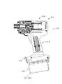
図1に、本発明の実施の形態の一例である電動スクリュードライバ101が示される。電動スクリュードライバ101は、モータハウジング101aとグリップ部101bとを有し、モータハウジング101a内には、直流ブラシレスモータ121、モータ駆動軸123、遊星歯車103を主体とする変速機構部105、スピンドル107が収納され、さらにスピンドル107の先端部にはビット取付用チャック109およびドライバビット111が配される。
【0019】
ドライバビット111は、本発明における「被加工材への所定の加工作業を行う工具」に対応する。一方、グリップ部101bの上端側にはトリガースイッチ113が設けられ、下端側にはバッテリ141が着脱自在に取り付けられる。モータハウジング101aとグリップ部101bとは、電動スクリュードライバ101の本体部103を構成する。
【0020】
本実施の形態にかかるバッテリ141の全体構成が図2に示される。バッテリ141は、バッテリハウジングの機能を奏するバッテリパック142に収容されて構成されている。バッテリパック142(バッテリ141)上部には、フック143および一対の装着ガイド145が配置されている。フック143は、バッテリパック142から上方に向かって出没自在に突出する。なお本実施の形態では、フック143の突出動作ないしバッテリパック142内への没入動作に連動して断続されるバッテリパック装着確認スイッチ144が設定されている。装着ガイド145は、バッテリパック142をグリップ部101b(図1参照)に装着する際、グリップ部101bの底部と係合する。
【0021】
具体的には、図1に示す電動スクリュードライバー101のグリップ部101bに対し、装着ガイド145を水平方向に係合させる。図2では、バッテリパック142のグリップ101b底部に対する装着方向が符号「S」を用いて示されている。当該装着ガイド145を用いて、更にバッテリパック141を水平方向に押し込むことにより、フック143は、装着方向に形成されたテーパー部143aがグリップ部101bの底部に押圧されることにより、バッテリパック142内に没入し、バッテリパック142の押し込みを許容する。これによりバッテリパック142がグリップ部101bに装着されることになる。なお本実施の形態では、当該フック143の移動動作に基づき、後述するバッテリパック装着確認スイッチ144が「バッテリ装着状態」を検出および出力する構成とされている。
【0022】
図3に示すように、本発明の実施の形態に係る電動スクリュードライバ101は、本体部103に設定されて直流ブラシレスモータ121の駆動制御を行う制御回路151、バッテリ141の駆動電流を直流ブラシレスモータ121へ供給する電源回路153、位置検出回路155、FETブリッジ157およびバッテリパック装着確認スイッチ144を主体として構成される。バッテリパック142内に収容されたバッテリ141は、接続端子部147を介して本体部103側の電源回路153に電気的に接続される。本実施の形態における制御回路151は、本発明における「駆動制御手段」に対応する要素である。また接続端子部147は、本発明における「第1の接続端子部」に対応する要素である。
【0023】
本実施の形態における直流ブラシレスモータ121は、接続端子部147および電源回路153を介してバッテリ141に接続されて駆動電流の供給を受けるとともに、制御回路151および当該制御回路151に連接されたFETブリッジ157に接続されて駆動制御を受ける。なお、本実施の形態にかかる直流ブラシレスモータ121は、三相式のバイポーラ駆動回路方式によって駆動される。
【0024】
特に図示しないもののFETブリッジ157には、直流ブラシレスモータ121を矩形波駆動するための6つのFET(電界効果型トランジスタ)が設定されており、これらのFETは、直流ブラシレスモータ121のロータ(便宜上特に図示しない)を駆動するための3つのコイル(電機子巻線)125U・125V・125Wに接続されている。そして、矩形波駆動用FETそれぞれのゲートに対する選択的な電圧印加により、コイル125U,125V,125Wに対し120度通電矩形波による駆動制御が行われる。
【0025】
位置検出回路155はホール素子を主体として構成されるとともに制御回路151に接続される。位置検出回路155は、直流ブラシレスモータ121のロータの回転位置を検出し、各コイル125U・125V・125Wへの通電に際しての相順を切り換えるために用いられる。
【0026】
バッテリパック装着確認スイッチ144は、本発明における「第2の接続端子部」に対応する要素であり、フック143(図2参照)に連動して断続されるよう構成されている。具体的には、フック143によりバッテリパック142がグリップ部101bに確定的に係止されていない状態にある場合には、バッテリパック装着確認スイッチ144は遮断されて、「バッテリパック装着解除状態」を検出し、制御回路151に出力する。一方、フック143によりバッテリパック142がグリップ部に係止された状態にある場合には、バッテリパック装着確認スイッチ144がON接続されて、「バッテリパック装着状態」を検出し、制御回路151に出力する。なお図3ではバッテリパック装着確認スイッチ144が接続された状態を示している。
【0027】
さらに図3に示すように、バッテリ141はバッテリパック142内に収容されるとともに、接続端子部147を介して本体部103側の電源回路153に接続される。バッテリパック142には、サーミスタを主体として構成される過熱防止部146が更に設けられており、バッテリ141放電中の異常加熱を防止する。
【0028】
接続端子部147は、雌形状のバッテリ側端子部147aと、当該バッテリ側端子部147aに嵌合係止される雄形状の本体側端子部147bによって構成されている。図3では、端子本体側部147bがバッテリ側端子部147aに嵌合された状態を示す。
【0029】
次に本実施の形態の作用について説明する。作業者が図1に示すトリガスイッチ113を操作すると、直流ブラシレスモータ121はバッテリ141を駆動源として回転駆動される。直流ブラシレスモータ121の回転運動は、変速機構部105において減速されつつ、モータ駆動軸123を介してスピンドル107へ伝達される。直流ブラシレスモータ121によってスピンドル107が回転駆動されることにより、スピンドル107先端のビット取付用チャック109に取り付けられたドライバビット111が回転駆動され、これによって被加工材に対するネジ締付作業が遂行される。
【0030】
ところで、電動スクリュードライバ101を使用するにあたり、バッテリパック142を図1に示すグリップ部101b下端部から取り外し、放電したバッテリ141を充電しあるいは交換する必要が生じてくる。このような場合、バッテリパック142は図2に示す装着ガイド145を介して、装着方向(符号S)とは反対向きにグリップ部101bから取り外される。その際、フック143によるバッテリパック142の係止が解除されて、バッテリパック装着確認スイッチ144が遮断されることになる。
【0031】
ところで、バッテリパック142が取り外され、再度バッテリパック142をグリップ部101に装着する場合、バッテリパック142の係止が不完全な場合が生じる。これにより、作業者がバッテリパック142をグリップ101bから不用意に取り外してしまう場合が生じ得る。電動スクリュードライバ101使用時であって直流ブラシレスモータ121駆動用の大電流が電源回路153を流れている状態において、バッテリパック142がグリップ部101から取り外すと、接続端子部147周辺にアーク(火花)が発生する可能性がある。
【0032】
この点、本実施の形態では、バッテリパック142のグリップ部101b(本体部103)への装着が不完全な場合、図4に示すようにバッテリパック装着確認スイッチ144が遮断され、制御回路151がバッテリ装着解除状態を検出する。すると制御回路151は、直流ブラシレスモータ121の駆動停止信号を出力し、図3に示すFETブリッジ157を介して直流ブラシレスモータ121の駆動を停止する。すなわち図4では、接続端子部147の接続が維持されているものの、バッテリ装着確認スイッチ144が遮断されているため直流ブラシレスモータ121の駆動は停止された状態が示される。
【0033】
一方、バッテリパック142が本体部103から離脱した状態が図5に示される。図5における接続端子部147では、バッテリ側端子部147aから本体側端子部147bが離脱した状態が示される。このとき既に直流ブラシレスモータ121の駆動が停止されているため、電源回路に駆動用大電流が流れることがなく、更に接続端子部147におけるアーク発生を効果的に防止することが可能となる。
【0034】
とりわけ本実施の形態では、フック143に設定されたバッテリパック装着確認スイッチ144の断続によって直流ブラシレスモータ121の駆動制御を行う構成としているため、バッテリパック142が不正に本体部103に装着された段階で、フック143に設定されたバッテリパック装着確認スイッチ144が遮断され、既に直流ブラシレスモータ121の駆動が停止されることになる。従って、直流ブラシレスモータ121の駆動を停止してから電源回路153の遮断までに十分な時間差が設定されるため、アーク発生防止および防爆対策に万全を期すことができる。
【0035】
さらに本実施の形態では、外観上はバッテリパック142がグリップ部101bに正しく装着されているように見えるにも拘わらず実際には装着が不完全な場合に、フック143に設定されたバッテリパック装着確認スイッチ144を介してモータ駆動が停止されるため、作業者にバッテリパック142の不正装着を迅速に察知させることが可能である。
【0036】
(第1の変更例)
本実施の形態の第1の変更例が図6ないし図9に示される。図6では、本発明の実施の携帯の変更例に係る電動スクリュードライバ201につき、直流ブラシレスモータ121を駆動するための回路構成例が示される。なお図6以降において、本発明の実施の形態と同等の構成を有する部材要素については同一符号を用いて説明することとする。図6に示すように、第1の変更例に係る電動スクリュードライバ201では、図3に示すバッテリパック装着確認スイッチ144に代えて、バッテリパック142の本体部103への装着状態を検出するための装着検出端子部149が設けられている。装着検出端子部149は、バッテリパック142側に設定された雌形状のバッテリ側端子部149aと、本体部103側に設定されてバッテリ側端子部149aに嵌合係止される雄形状の本体側端子部149bとを有する。
【0037】
本変更例においては、装着検出端子部149における本体側端子部149bの長さは、接続端子部147における本体側端子部147bの長さよりも短く構成されている。一方、装着検出端子部149におけるバッテリ側端子部149aは、本体側端子部149aに対応して、接続端子部147のバッテリ側端子部147aよりも浅く形成されている。
【0038】
第1の変更例における直流ブラシレスモータ121の構成、制御回路151、電源回路153、位置検出回路155、FETブリッジ157、接続端子部147、過熱防止部146については、上述の実施形態と同等の構成・機能とされているため、便宜上その詳細な説明を省略する。
【0039】
図7ないし図9には、本変更例における本体部103へのバッテリパック142の各種装着状態が示される。このうち図7では、バッテリパック142が本体部103に正常に装着された状態(以下「正常装着状態」という)が示される。図8では、バッテリパック142が本体部103から離脱し始めた状態(以下「離脱開始状態」という)が示される。図9では、バッテリパック142が本体部103から完全に離脱した状態(以下「バッテリ離脱状態」という)が示される。
【0040】
図7に示す正常装着状態においては、接続端子部147および装着検出端子部149ともに接続状態が維持される。従って、バッテリ141は接続端子部147を通じて本体部103側に電気的に接続されて駆動電流を供給するとともに、制御回路151は、装着検出端子部149を介してバッテリパック142の正常装着状態を検出する。
【0041】
バッテリパック142の本体部103への装着が不完全であった場合、作業時にバッテリパック142を不用意に本体部から取り外してしまう場合が生じ得る。バッテリパック142が本体部103から離脱を開始し始めた状態では、装着検出端子部149の本体側端子部149bが、接続端子部147の本体側端子部147bよりも短寸法とされているため、図8に示すように、装着検出端子部149が遮断される一方、接続端子部147では接続状態が維持される。
【0042】
この状態では、バッテリ141は接続端子部147を通じて本体部103側に電気的に接続されるのに対し、装着検出端子部149が遮断されることによって制御回路151は、バッテリパック142が離脱開始状態にあることを検出する。これにより制御回路151は直流ブラシレスモータ121の駆動を停止するよう制御信号を出力する。
【0043】
さらにバッテリパック142が本体部103から完全に離脱する場合、図9に示すように、装着検出端子部149のみならず接続端子部147も遮断されることになる。この場合、接続端子部147が遮断される時点では、既に直流ブラシレスモータ121は駆動停止される。これにより、当該変更例において、直流ブラシレスモータ121の駆動が停止された後で電源回路が遮断される構成が得られ、アーク発生を効果的に防止し、防爆状態にて電動スクリュードライバを使用することが可能となる。
【0044】
(第2の変更例)
次に図10から12を参照しつつ本実施の形態の第2の変更例について説明する。図10には第2の変更例に係る電動スクリュードライバ201の全体構造が示される。なお第2の変更例の各構成要素のうち上記実施の形態ないし第1の変更例と同等の構成要素については便宜上同一の符号を用い、かつ詳細な説明を省略するものとする。
【0045】
図10に示すように、第2の変更例に係る電動スクリュードライバ201は、モータハウジング101aとグリップ部101bとからなる本体部103と、バッテリ141を収容したバッテリパック142とを有する。バッテリパック142はグリップ部101bの下端側に取り付けられるとともに、バッテリカバー210によって覆蓋されている。
【0046】
バッテリカバー210の詳細な構造が図11に示される。バッテリカバー210は、回転中心211回りに回動可能に、グリップ部101bの後端側に取り付けられている。また回転中心211と対向する側の端部には、バッテリカバー210を本体部103に係止保持するための係止部213が設けられている。バッテリパック142を本体部103に装着するには、バッテリパック142の両側面部に形成されたレール状の装着ガイド145を用いて、バッテリパック142をグリップ部101bにセットする。図11では、バッテリパック142の装着方向が符号Sで示される。装着ガイド145に案内されてグリップ部101bに装着されたバッテリパック142は、特に図示しないものの当該バッテリパック142に設けられたフック143を介してグリップ部101b下端に係止される。
この状態でバッテリカバー210をグリップ部101b側へ回転し、バッテリパック142を覆蓋した状態のバッテリカバー210を、係止部213を用いて本体部103に係止保持させる。図10はこの状態を示す。
【0047】
反対にバッテリパック142を取り外す場合には、係止部213の係止を解除してバッテリカバー210を回転中心211周りに回転させて、バッテリパック142を露出させる。そして図示しないフックを解除しつつ装着ガイド145を用いてバッテリパック142を水平に引き出す(図11では符号Sで示される方向)。これによってバッテリパック142が本体部103から取り外される。
【0048】
第2の変更例に係る電動スクリュードライバ201には、バッテリカバー210の装着状況に応じて断続されるバッテリカバー装着確認スイッチ220が設定されている。このバッテリカバー装着確認スイッチ220は、バッテリカバー210によるバッテリパック142(ないしバッテリ141)の覆蓋動作に応じて断続される構成とされている。
【0049】
第2の変更例における電動スクリュードライバ201の駆動用回路図が図12に示される。電動スクリュードライバ201は、概略的に見て本体部103とバッテリパック142を有するとともに、本体部103内には直流ブラシレスモータ121、制御回路を有する駆動制御手段151、電源回路153、位置検出回路155、FETブリッジ157が配置されている。これらの要素の詳細については上記実施の形態と同等である。さらに第2の変更例では、バッテリカバー210によるバッテリ141の覆蓋動作に応じて作動されるバッテリカバー装着スイッチ220が駆動制御手段151内の制御回路に電気的に接続される。
【0050】
バッテリパック142内には、バッテリ141、加熱防止部146、接続端子部147、装着検出端子部149が配置されている。これらの要素の詳細については上記実施の形態と同等である。
【0051】
第2の変更例では、バッテリパック装着確認スイッチ144が遮断された場合あるいは装着検出端子部149において本体側端子部149bがバッテリ側端子部149aから離脱した場合のみならず、バッテリカバー装着確認スイッチ220が遮断された場合にも、電源回路153の遮断に先立つ形で、駆動制御手段151は直流ブラシレスモータ121の駆動を停止する。すなわちバッテリカバー210の装着が解除された場合、換言すればバッテリカバー210によるバッテリパック142の覆蓋が解除された場合には、直流ブラシレスモータ121の駆動を迅速に停止する構成とされる。従って、その後バッテリパック142が本体部103から取り外されて電源回路153が遮断されたとしても、バッテリパック142が本体部103から離脱することによる接続端子部147でのアーク発生が防止され、電動スクリュードライバ201を防爆状態において使用することが可能となる。
【0052】
なおバッテリカバー210によるバッテリパック142(バッテリ141)の覆蓋解除の態様として、バッテリカバー210の係止部213による本体部103への係止保持が解除された場合に覆蓋が解除されたとする態様、回転中心211においてバッテリカバー210が回転した場合に覆蓋が解除されたとする態様、バッテリカバー210のグリップ部101bへの近接状態を磁石等を用いて検出し、近接状態が検出されなくなった場合に覆蓋が解除されたとする態様など、様々な形態が可能である。
【0053】
上記した変更例の更なる変更形態として、バッテリパック142と本体部103(グリップ部101b)との間にアダプタが配置されるような場合には、このアダプタの装着状態に応じて断続されるスイッチを設け、当該アダプタ装着確認スイッチが切断された場合には、電源回路153の遮断に先立つ形で、直流ブラシレスモータ121の駆動を停止する形態が採用可能である。
【0054】
あるいは本体部103(グリップ部101b)側にバッテリパック142を係止保持するためのロックダイヤル式フック等が設置されるような場合には、このロックダイヤルの位置に基づいて、バッテリパック142が本体部103側に係止されているか否かを検出可能なスイッチを設け、当該ロックダイヤル位置検出スイッチが切断された場合には、電源回路153の遮断に先立つ形で、直流ブラシレスモータ121の駆動を停止する形態が採用可能である。
【0055】
なお上記アダプタないしロックダイヤルに関連してスイッチを設ける場合、マグネットと、当該マグネットの近接に感応する磁気センサーを適宜組み合わせる等の具体的構成が採用可能である。
【0056】
上記した実施の形態および各変更例においては、接続端子部147および装着検出端子部149につき、バッテリパック142側に雄形状の端子部を設定し、本体部103側に雌形状の端子部を設定する構成も可能である。またドライバビット111駆動のため、直流ブラシレスモータ以外のモータを使用してもよい。
もちろん本発明は、上記実施の形態で説明した電動スクリュードライバのみならず、広くバッテリ駆動式電動工具一般に適用が可能である。
【0057】
またフック143に連動して作動するバッテリパック装着確認スイッチ144を採用した実施の形態、接続端子部147よりも短い雄形状端子を有する装着検出端子149を採用した変更例、さらにバッテリカバー装着確認スイッチ220を採用した変更例については、これらを全て採用した形態ないしこれらの一部を採用した形態等、自在に構成することが可能である。組み合わせて構成することも可能である。このように構成すれば、バッテリ装着確認スイッチ144、装着検出端子149およびバッテリーカバー装着確認スイッチ220のうちのいずれかが作動不良を起こした場合であっても、バッテリ141による駆動電流遮断に先立って、直流ブラシレスモータ121の駆動を確実に停止することが可能となる。
【0058】
またバッテリの残量表示部が設定されたタイプの場合には、当該残量表示部用の接続端子の長さを、電源回路用の接続端子の長さよりも短く形成するといった変更例が可能である。このように構成することで、バッテリパック142のグリップ部101bに対する装着が不完全で、バッテリパック142を不用意に取り外す場合、残量表示部側の接続端子が電源回路側の接続端子よりも先に遮断されることになる。これにより直流ブラシレスモータ121の駆動が停止された後で、電源回路が遮断される構成が得られ、アーク発生を効果的に防止し、防爆状態にて電動スクリュードライバを使用することが可能となる。
【0059】
【発明の効果】
本発明によれば、バッテリ駆動式電動工具に装着されたバッテリを取り外す場合の機材等への悪影響防止に有効な技術が提供されることとなった。
【図面の簡単な説明】
【図1】 本発明の実施の形態に係る電動スクリュードライバの全体構成を示す。
【図2】 本発明の実施の形態として用いられるバッテリおよびバッテリパックの構成を示す。
【図3】 本発明の実施の形態に係る電動スクリュードライバにおけるモータ駆動のための回路構成を示す。
【図4】 図3に示すモータ駆動回路構成につき、バッテリパックの本体部へのフック係止が解除された状態を示す。
【図5】 同じく図3に示すモータ駆動回路構成につき、バッテリパックが本体部から離脱した状態を示す。
【図6】 本実施の形態の第1の変更例を示す図である。
【図7】 第1の変更例において、バッテリパックが本体部に装着されている状態を示す。
【図8】 図6に示す第1の変更例につき、バッテリパックが本体部から離脱し始めた状態を示す。
【図9】 同じく図6に示す第1の変更例につき、バッテリパックが本体部から完全に離脱した状態を示す。
【図10】 本実施の形態の第2の変更例を示す図である。
【図11】 第2の変更例におけるバッテリとバッテリカバーの関係を示す図である。
【図12】 第2の変更例におけるモータ駆動のための回路構成を示す。
【符号の説明】
101 電動スクリュードライバ
101a モータハウジング
101b グリップ部
103 本体部
105 変速機構部
107 スピンドル
111 ドライバビット
121 直流ブラシレスモータ
125U,V,W コイル
141 バッテリ
142 バッテリパック
143 フック
144 バッテリパック装着確認スイッチ
145 装着ガイド
146 加熱防止部
147 接続端子部
149 装着検出端子部
151 駆動制御手段
153 電源回路
155 位置検出回路
157 FETブリッジ
210 バッテリカバー
211 回転中心
213 係止部
220 バッテリカバー装着確認スイッチ[0001]
BACKGROUND OF THE INVENTION
The present invention relates to a technique capable of suppressing adverse effects on equipment caused by removing a battery mounted on a battery-powered electric tool during work, and thus thorough explosion-proof during work.
[0002]
[Prior art]
In a battery-driven electric tool, a driving current is supplied to a tool bit driving motor by a battery. For example, in a conventional screw driver that is an example of a battery-driven electric tool, a battery is detachably attached to a main body portion that includes a motor housing and a hand grip. Specifically, a hand grip is connected to a motor housing that houses a motor for driving a driver bit to form a main body portion, and a battery is detachably attached to a lower end portion of the hand grip. At this time, the battery constitutes a power supply circuit for driving the motor via the connection terminal. As a result, the battery supplies a drive current to the motor via the power supply circuit.
[0003]
In the conventional battery-driven electric tool configured as described above, since the battery is detachably attached to the main body, the battery may be removed from the main body when performing an operation using the electric tool. Can occur. In this case, as described above, the battery forms a motor drive power supply circuit via the connection terminal and supplies a drive current to the motor in operation. There is a possibility that the power supply circuit is suddenly cut off by being removed from the lower end. If the power supply circuit for driving the motor is cut off while the motor is driven, an arc is generated between the contacts, which may adversely affect the corrosion resistance of the equipment. There is a high need to take preventive measures.
[0004]
[Problems to be solved by the invention]
The present invention has been made in view of this point, and an object of the present invention is to provide a technique effective in preventing adverse effects on equipment when a battery mounted on a battery-driven electric tool is removed.
[0005]
[Means for Solving the Problems]
In order to achieve the above object, the invention described in each claim is configured.
According to the first aspect of the present invention, a battery-driven electric tool having a main body, a battery, a drive control unit, and a power supply circuit is configured. The main body includes a tool bit that performs a predetermined processing operation on the workpiece, and a motor that drives the tool bit. The battery is detachably locked to the main body to drive the motor. The drive control means controls driving of the motor by the battery. The power supply circuit supplies drive current from the battery to the motor.
[0006]
The drive control means in the present invention is While the battery is supplying drive current to the motor through the power circuit, When the battery is unlocked from the main body, the motor is stopped before the power supply circuit is shut off. Note that “unlocking the battery with respect to the main body” includes not only the state in which the battery is detached from the main body, but also the state in which the battery is not completely locked with the main body, that is, the battery is correctly engaged with the main body. Although it seems to have stopped, it is the meaning which includes the state which is not actually latched, ie, the unauthorized mounting state of a battery widely.
[0007]
When the latch of the battery to the main body is released, the drive control means stops driving the motor before the power supply circuit is shut off. As a result, even if the battery is disconnected from the main body while the battery is supplying drive current to the motor through the power circuit, and the power circuit is shut off, the motor will Since the driving is stopped, it is possible to prevent the durability of the equipment from being reduced due to a large current for driving the motor or to prevent an arc from being generated at the connection terminal. From the viewpoint of safety, it is preferable to set a sufficient time difference so that no arc is generated after the motor driving is stopped until the power supply circuit is shut off.
[0008]
In the present invention, “tool bits for performing predetermined machining operations” widely include those used for battery-type drills, saws, grinders, impact drivers, impact wrenches, cutters, trimmers, circular saws, reciprocating saws, etc. The The motor for driving the tool bit typically corresponds to a DC motor or a DC brushless motor. The main body preferably has a motor housing and a hand grip as appropriate in accordance with the set processing operation. In this case, the present invention includes a form in which the battery is attached to either the motor housing or the hand grip portion. Typically, a battery is a rechargeable storage battery. Further, the power supply circuit that supplies the drive current from the battery to the motor can adopt either a form including the drive control means in the middle or a form not including it. Further, in the present invention, “stopping the driving of the motor” includes a mode in which the motor drive control circuit and the like are physically disconnected and stopped based on the release of the locked state of the battery from the main body, A configuration in which a motor drive stop signal or the like based on is generated and motor drive is stopped based on this signal is possible.
[0009]
(Invention of Claim 2)
In the battery-driven electric tool described above, a configuration in which a locking hook is set to detachably lock the battery to the main body is preferable. In this case, it is preferable that the drive control means stop driving the motor prior to shutting off the power supply circuit when the lock to the main body of the battery by the locking hook is released. As a way to release the lock by the locking hook, the lock is not completely unlocked by the locking hook. Complete embodiments are also encompassed. Thereby, the effect | action of detecting and alert | reporting the unauthorized mounting state of the battery with respect to a main-body part is also show | played together. In other words, in a state where the battery is illegally attached to the main body via the locking hook, the driving of the motor is stopped, so that the operator can quickly detect that the battery is illegally attached. Become. The locking hook can be set on either the battery side or the main body side.
[0010]
(Invention of Claim 3)
In addition, for the battery-driven electric tool, a first connection terminal portion that constitutes a power circuit between the battery and the main body portion, and a second connection that is intermittently connected (connected or disconnected) depending on the battery mounting state. It is preferable to set the terminal portion. And it is preferable to set so that the driving of the motor is stopped by releasing the connection of the second connection terminal part before the connection of the first connection terminal part is released. In addition, as a mode of stopping the driving of the motor, a mode in which the driving control circuit of the motor is physically disconnected and stopped by releasing the connection of the second connecting terminal unit, or the second connecting terminal unit Various configuration modes are possible such as generating a motor drive stop signal or the like based on the disconnection and stopping the motor drive based on this signal.
[0011]
(Invention of Claim 4)
In the battery-driven electric tool described in claim 3, it is preferable that the terminal length of the second connection terminal portion is configured to be shorter than the terminal length of the first connection terminal portion. That is, when the battery is about to be detached from the main body, the terminal on the second connection part side having a short terminal length is first removed, and then the terminal on the first connection terminal part side having a longer terminal length is detached. The structure which does is preferable. In this case, when the power supply circuit for driving the motor is disconnected by disconnecting the first connection terminal, the motor drive is already stopped by disconnecting the first connection terminal. The large current for use prevents the adverse effects on the equipment and the working environment, and this effect can be achieved with a simple configuration in which the length of the terminal of each terminal portion is set to be long or short.
[0012]
(Invention of Claim 5)
According to the invention of claim 5, While the battery is supplying drive current to the motor through the power circuit, When the battery lock is released, By drive control means for controlling the drive of the motor A configuration relating to a method of using a battery-powered electric tool having a feature of stopping driving of a motor prior to interruption of driving current to the motor is shown. As a result, when the battery is detached from the main body, since the driving of the motor has already been stopped, the generation of an arc between the battery and the main body due to a large current for driving the motor is effectively suppressed. Thus, explosion-proofing when the battery-driven electric tool is used for work is achieved. Of course, it is also possible to constitute a usage method in which the features of the battery-powered electric tool according to claims 2 to 4 are appropriately combined.
[0013]
(Invention of Claim 6)
In the invention described in claim 6, the battery is attached to the main body through the attaching means. The “attachment” or “attachment means” widely includes a mode in which the battery is connected to the main body. Specifically, it is difficult or impossible to remove the battery from the main body unless the attachment means disposed between the battery and the main body is released as well as a mode in which the battery is definitely locked to the main body. Such a connection form is widely included.
[0014]
In the present invention, While the battery is supplying drive current to the motor through the power circuit, When the attachment of the battery to the main body by the attachment means is released, the drive control means stops driving the motor prior to the interruption of the power supply circuit. Therefore, even if a situation occurs in which the battery is detached from the main body while the battery is supplying drive current to the motor through the power supply circuit, the motor is removed in the form prior to the interruption of the power supply circuit by releasing the attachment to the main body of the battery. Since the driving is stopped, it is possible to prevent the durability of the equipment from being reduced due to a large current for driving the motor or to prevent an arc from being generated at the connection terminal. The configuration of the present invention can be set separately from, or in combination with, the configuration of each of the above-described inventions, for example, the configuration in which the driving of the motor is stopped based on the release of the locking hook or the connection terminal portion.
[0015]
(Invention of Claim 7)
As the attachment means in the battery-driven electric tool according to claim 6, for example, a battery cover that covers the battery on the main body can be employed. In this case, it is preferable that the driving of the motor is stopped prior to the interruption of the power supply circuit by releasing the cover by the battery cover. It should be noted that both the form in which the battery cover covers the battery and the battery is fixedly held on the main body and the form in which the battery cover simply covers the battery are included in the present invention.
[0016]
(Invention of Claim 8)
Alternatively, for example, an adapter disposed between the battery and the main body can be employed as the attachment means in the battery-driven electric tool according to claim 6. In this case, when the arrangement between the battery of the adapter and the main body is released, it is preferable that the driving of the motor is stopped before the power supply circuit is shut off.
[0017]
(Invention of Claim 9)
According to the invention of claim 9, While the battery is supplying drive current to the motor through the power circuit, When the attachment to the main body of the battery by the attachment means is released, By drive control means for controlling the drive of the motor A configuration relating to a method of using a battery-powered electric tool having a feature of stopping driving of a motor prior to interruption of driving current to the motor is shown. As a result, the motor is already stopped when the battery is detached from the main body based on the release of the attachment means, so that an arc is generated between the battery and the main body due to a large current for driving the motor. Is effectively suppressed, and explosion-proofing when the battery-powered electric tool is used for work is achieved.
[0018]
DETAILED DESCRIPTION OF THE INVENTION
Hereinafter, embodiments of the present invention will be described in detail with reference to the drawings.
FIG. 1 shows an
[0019]
The driver bit 111 corresponds to “a tool for performing a predetermined machining operation on a workpiece” in the present invention. On the other hand, a
[0020]
The entire configuration of the
[0021]
Specifically, the mounting
[0022]
As shown in FIG. 3, the
[0023]
The
[0024]
Although not shown, the
[0025]
The
[0026]
The battery pack attachment confirmation switch 144 is an element corresponding to the “second connection terminal portion” in the present invention, and is configured to be intermittently connected to the hook 143 (see FIG. 2). Specifically, when the
[0027]
Further, as shown in FIG. 3, the
[0028]
The
[0029]
Next, the operation of this embodiment will be described. When the operator operates the
[0030]
By the way, when using the
[0031]
By the way, when the
[0032]
In this regard, in the present embodiment, when the
[0033]
On the other hand, a state where the
[0034]
In particular, in the present embodiment, since the drive control of the
[0035]
Further, in the present embodiment, when the
[0036]
(First change example)
A first modification of the present embodiment is shown in FIGS. FIG. 6 shows a circuit configuration example for driving the
[0037]
In the present modification, the length of the main body side terminal portion 149b in the attachment
[0038]
The configuration of the
[0039]
7 to 9 show various attachment states of the
[0040]
In the normal mounting state shown in FIG. 7, the connection state is maintained for both the
[0041]
If the
[0042]
In this state, the
[0043]
Further, when the
[0044]
(Second modification)
Next, a second modification of the present embodiment will be described with reference to FIGS. FIG. 10 shows the overall structure of the
[0045]
As shown in FIG. 10, the
[0046]
The detailed structure of the
In this state, the
[0047]
On the contrary, when removing the
[0048]
In the
[0049]
A circuit diagram for driving the
[0050]
In the
[0051]
In the second modified example, not only when the battery pack attachment confirmation switch 144 is interrupted or when the main body side terminal portion 149b is detached from the battery
[0052]
In addition, as an aspect of releasing the cover of the battery pack 142 (battery 141) by the
[0053]
As a further modification of the above-described modification example, when an adapter is arranged between the
[0054]
Alternatively, when a lock dial type hook or the like for locking and holding the
[0055]
When a switch is provided in association with the adapter or the lock dial, a specific configuration such as a combination of a magnet and a magnetic sensor sensitive to the proximity of the magnet can be adopted.
[0056]
In the above-described embodiment and each modified example, for the
Of course, the present invention can be widely applied not only to the electric screw driver described in the above embodiment but also to battery-driven electric tools in general.
[0057]
Also, an embodiment employing a battery pack attachment confirmation switch 144 that operates in conjunction with the hook 143, a modification employing an
[0058]
In the case of the type in which the battery remaining amount display portion is set, a modification example is possible in which the length of the connection terminal for the remaining amount display portion is formed shorter than the length of the connection terminal for the power supply circuit. is there. With this configuration, when the
[0059]
【The invention's effect】
ADVANTAGE OF THE INVENTION According to this invention, the technique effective in preventing the bad influence to the equipment etc. at the time of removing the battery with which the battery drive type electric tool was mounted | worn was provided.
[Brief description of the drawings]
FIG. 1 shows an overall configuration of an electric screwdriver according to an embodiment of the present invention.
FIG. 2 shows a configuration of a battery and a battery pack used as an embodiment of the present invention.
FIG. 3 shows a circuit configuration for driving a motor in the electric screwdriver according to the embodiment of the present invention.
4 shows a state in which the hook engagement with the main body of the battery pack is released in the motor drive circuit configuration shown in FIG.
5 shows a state in which the battery pack is detached from the main body in the motor drive circuit configuration shown in FIG.
FIG. 6 is a diagram showing a first modification example of the present embodiment.
FIG. 7 shows a state in which the battery pack is attached to the main body in the first modification.
FIG. 8 shows a state in which the battery pack starts to be detached from the main body according to the first modification shown in FIG.
FIG. 9 shows a state in which the battery pack is completely detached from the main body according to the first modification shown in FIG. 6;
FIG. 10 is a diagram showing a second modification of the present embodiment.
FIG. 11 is a diagram showing a relationship between a battery and a battery cover in a second modified example.
FIG. 12 shows a circuit configuration for driving a motor in a second modification.
[Explanation of symbols]
101 Electric screwdriver
101a motor housing
101b Grip part
103 Main body
105 Transmission mechanism
107 spindle
111 driver bits
121 DC brushless motor
125U, V, W coil
141 battery
142 battery pack
143 hook
144 Battery pack installation confirmation switch
145 wearing guide
146 Heating prevention part
147 Connection terminal
149 Wear detection terminal
151 Drive control means
153 Power supply circuit
155 Position detection circuit
157 FET bridge
210 Battery cover
211 Center of rotation
213 Locking part
220 Battery cover installation confirmation switch
Claims (9)
前記本体部に着脱自在に係止されて前記モータを駆動するバッテリと、
前記バッテリによる前記モータの駆動を制御する駆動制御手段と、
前記バッテリから前記モータへ駆動電流を供給する電源回路を有するバッテリ駆動式電動工具であって、
前記駆動制御手段は、前記バッテリが前記電源回路を通じて駆動電流を前記モータに供給している最中に、前記バッテリの前記本体部への係止が解除される場合に、前記電源回路の遮断に先立って前記モータの駆動を停止することを特徴とするバッテリ駆動式電動工具。A main body having a tool bit for performing a predetermined machining operation on a workpiece and a motor for driving the tool bit;
A battery that is detachably locked to the main body and drives the motor;
Drive control means for controlling driving of the motor by the battery;
A battery-driven electric tool having a power supply circuit for supplying a drive current from the battery to the motor,
The drive control means shuts off the power supply circuit when the battery is released from being locked to the main body while the battery is supplying drive current to the motor through the power supply circuit. A battery-powered electric tool characterized by stopping driving of the motor in advance.
前記バッテリを前記本体部に着脱自在にロックするための係止フックを有し、
前記駆動制御手段は、前記係止フックによる前記バッテリの前記本体部へのロックが解除される場合に、前記電源回路の遮断に先立って前記モータの駆動を停止することを特徴とするバッテリ駆動式電動工具。The battery-powered electric tool according to claim 1,
A locking hook for detachably locking the battery to the main body,
The drive control means stops driving the motor prior to shutting off the power supply circuit when the lock of the battery to the main body by the locking hook is released. Electric tool.
前記バッテリと前記本体部との間には、前記電源回路を構成する第1の接続端子部と、前記バッテリの装着状態に応じて断続される第2の接続端子部とを有し、前記バッテリが前記本体部から離脱する場合に、前記第1の接続端子部の接続が解除される前に、前記第2の接続端子部の接続が解除されることによって前記モータの駆動が停止されることを特徴とするバッテリ駆動式電動工具。The battery-powered electric tool according to claim 1,
Between the battery and the main body portion, there is a first connection terminal portion that constitutes the power supply circuit, and a second connection terminal portion that is interrupted according to a mounting state of the battery, and the battery Is detached from the main body, the drive of the motor is stopped by releasing the connection of the second connection terminal before the connection of the first connection terminal is released. A battery-powered electric tool characterized by
前記バッテリが電源回路を通じて駆動電流を前記モータに供給している最中に、前記バッテリの前記本体部への係止が解除される場合に、前記モータの駆動を制御する駆動制御手段によって前記モータへの駆動電流の遮断に先立って前記モータの駆動を停止し、これによって前記バッテリと本体部との間のアーク発生を抑制し防爆状態とすることを特徴とするバッテリ駆動式電動工具の使用方法。A battery-driven electric tool in which a battery for supplying a driving current to the motor is detachably locked to a main body having a motor and a tool bit driven by the motor.
While the battery is supplying a drive current to the motor through a power supply circuit , the motor is controlled by a drive control means for controlling the drive of the motor when the battery is released from being locked to the main body. Prior to interruption of the drive current to the battery, the driving of the motor is stopped, thereby suppressing the generation of arc between the battery and the main body and making it in an explosion-proof state. .
前記本体部に着脱自在に係止されて前記モータを駆動するバッテリと、
前記バッテリを前記本体部に付設する付設手段と、
前記バッテリによる前記モータの駆動を制御する駆動制御手段と、
前記バッテリから前記モータへ駆動電流を供給する電源回路を有するバッテリ駆動式電動工具であって、
前記駆動制御手段は、前記バッテリが前記電源回路を通じて駆動電流を前記モータに供給している最中に、前記付設手段による付設が解除される場合に、前記電源回路の遮断に先立って前記モータの駆動を停止することを特徴とするバッテリ駆動式電動工具。A main body having a tool bit for performing a predetermined machining operation on a workpiece and a motor for driving the tool bit;
A battery that is detachably locked to the main body and drives the motor;
Attaching means for attaching the battery to the main body,
Drive control means for controlling driving of the motor by the battery;
A battery-driven electric tool having a power supply circuit for supplying a drive current from the battery to the motor,
The drive control means is configured to release the power supply circuit prior to shutting off the power supply circuit when the attachment by the attachment means is released while the battery is supplying drive current to the motor through the power supply circuit . A battery-driven electric tool characterized by stopping driving.
前記モータへ駆動電流を供給するバッテリが付設手段を介して着脱自在に付設されてなるバッテリ駆動式電動工具につき、
前記バッテリが前記電源回路を通じて駆動電流を前記モータに供給している最中に、前記付設手段による前記バッテリの前記本体部への付設が解除される場合に、前記モータの駆動を制御する駆動制御手段によって前記モータへの駆動電流の遮断に先立って前記モータの駆動を停止し、これによって前記バッテリと本体部との間のアーク発生を抑制し防爆状態とすることを特徴とするバッテリ駆動式電動工具の使用方法。For a body having a motor and a tool bit driven by the motor,
Regarding a battery-driven electric tool in which a battery for supplying a driving current to the motor is detachably attached via attachment means,
While said battery is supplying a driving current through the power supply circuit to the motor, when attached to the main body of the battery by the attaching device is released, the drive control for controlling the driving of the motor The drive of the motor is stopped prior to the interruption of the drive current to the motor by means, thereby suppressing the generation of arc between the battery and the main body, and making it an explosion-proof state. How to use the tool.
Priority Applications (4)
| Application Number | Priority Date | Filing Date | Title |
|---|---|---|---|
| JP2002072890A JP3973459B2 (en) | 2002-03-15 | 2002-03-15 | Battery-powered power tool and method of using battery-powered power tool |
| US10/386,876 US7053567B2 (en) | 2002-03-15 | 2003-03-12 | Power tools |
| DE10311070A DE10311070B4 (en) | 2002-03-15 | 2003-03-13 | Power tool with a battery |
| CA002432512A CA2432512C (en) | 2002-03-15 | 2003-06-17 | Power tools |
Applications Claiming Priority (2)
| Application Number | Priority Date | Filing Date | Title |
|---|---|---|---|
| JP2002072890A JP3973459B2 (en) | 2002-03-15 | 2002-03-15 | Battery-powered power tool and method of using battery-powered power tool |
| CA002432512A CA2432512C (en) | 2002-03-15 | 2003-06-17 | Power tools |
Publications (2)
| Publication Number | Publication Date |
|---|---|
| JP2003266334A JP2003266334A (en) | 2003-09-24 |
| JP3973459B2 true JP3973459B2 (en) | 2007-09-12 |
Family
ID=34227253
Family Applications (1)
| Application Number | Title | Priority Date | Filing Date |
|---|---|---|---|
| JP2002072890A Expired - Lifetime JP3973459B2 (en) | 2002-03-15 | 2002-03-15 | Battery-powered power tool and method of using battery-powered power tool |
Country Status (4)
| Country | Link |
|---|---|
| US (1) | US7053567B2 (en) |
| JP (1) | JP3973459B2 (en) |
| CA (1) | CA2432512C (en) |
| DE (1) | DE10311070B4 (en) |
Cited By (1)
| Publication number | Priority date | Publication date | Assignee | Title |
|---|---|---|---|---|
| KR20180119030A (en) * | 2017-04-24 | 2018-11-01 | 엘지전자 주식회사 | Cleaner |
Families Citing this family (26)
| Publication number | Priority date | Publication date | Assignee | Title |
|---|---|---|---|---|
| EP1805863B1 (en) * | 2004-10-18 | 2013-06-26 | Black & Decker, Inc. | Cordless power system |
| US20060112570A1 (en) * | 2004-11-04 | 2006-06-01 | Serdynski David P | Power tools, battery chargers and batteries |
| US7492125B2 (en) * | 2004-11-04 | 2009-02-17 | Milwaukee Electric Tool Corporation | Power tools, battery chargers and batteries |
| US7317290B2 (en) * | 2004-12-29 | 2008-01-08 | Sauer-Danfoss Inc. | Tandem battery powered inverter and method of implementing the same |
| JP4993404B2 (en) * | 2006-06-21 | 2012-08-08 | 日立工機株式会社 | Portable power tools |
| JP5192674B2 (en) * | 2006-09-07 | 2013-05-08 | 日立工機株式会社 | Electric tool |
| US8253285B2 (en) * | 2007-04-27 | 2012-08-28 | Hitachi Koki Co., Ltd. | Power tool |
| US20090033286A1 (en) * | 2007-07-31 | 2009-02-05 | Dean La Rosa | Cell and Supercapacitor Battery Pack |
| JP5114171B2 (en) * | 2007-11-28 | 2013-01-09 | 伊東電機株式会社 | Electric mower |
| US7990005B2 (en) * | 2008-02-07 | 2011-08-02 | Atlas Dynamic Devices, Llc | Power transmission tool and system |
| JP4582177B2 (en) * | 2008-03-31 | 2010-11-17 | パナソニック電工株式会社 | Electric tool |
| JP5354363B2 (en) * | 2009-06-16 | 2013-11-27 | 日立工機株式会社 | Electric tool |
| DE102010001372A1 (en) * | 2010-01-29 | 2011-08-04 | Robert Bosch GmbH, 70469 | Restart protection for battery operated electrical appliances |
| CN102958651B (en) * | 2010-07-02 | 2016-04-20 | 胡斯华纳有限公司 | Battery-powered tools |
| CN103347658B (en) | 2011-02-10 | 2016-01-06 | 株式会社牧田 | Electric tool |
| JP6154328B2 (en) | 2011-02-14 | 2017-06-28 | コーニンクレッカ フィリップス エヌ ヴェKoninklijke Philips N.V. | Electrical means to limit leakage current in battery-operated patient-connected medical devices |
| JP2014525840A (en) | 2011-07-24 | 2014-10-02 | 株式会社マキタ | Power tool adapter, power tool system, and method for wirelessly communicating maintenance information thereof |
| EP2815500A2 (en) * | 2012-02-15 | 2014-12-24 | Hitachi Koki Co., Ltd. | Electric working machine |
| JP5722976B2 (en) * | 2013-10-04 | 2015-05-27 | 株式会社マキタ | Work tools |
| JP6345510B2 (en) * | 2014-06-30 | 2018-06-20 | 株式会社マキタ | Nut tightening machine |
| EP3970175A4 (en) | 2019-05-13 | 2023-01-11 | Milwaukee Electric Tool Corporation | Contactless trigger with rotational magnetic sensor for a power tool |
| CN114641599B (en) * | 2019-11-07 | 2024-08-06 | 工机控股株式会社 | Handheld power equipment |
| CN113467277A (en) * | 2020-03-31 | 2021-10-01 | 苏州宝时得电动工具有限公司 | Control system of electric control bag |
| USD947636S1 (en) | 2020-10-14 | 2022-04-05 | Black & Decker Inc. | Impact tool |
| USD956501S1 (en) | 2020-11-06 | 2022-07-05 | Black & Decker Inc. | Impact tool |
| JPWO2023286849A1 (en) * | 2021-07-15 | 2023-01-19 |
Family Cites Families (17)
| Publication number | Priority date | Publication date | Assignee | Title |
|---|---|---|---|---|
| US5277261A (en) * | 1992-01-23 | 1994-01-11 | Makita Corporation | Tightening tool |
| JP3126571B2 (en) | 1993-11-12 | 2001-01-22 | 帝人製機株式会社 | Fluid circuit for working cylinder of civil engineering construction machinery |
| JPH07173549A (en) | 1993-12-17 | 1995-07-11 | Kawasaki Steel Corp | Method for recovering metallic zinc and iron from dust containing zinc and iron |
| US5738177A (en) * | 1995-07-28 | 1998-04-14 | Black & Decker Inc. | Production assembly tool |
| DE19626731A1 (en) * | 1996-07-03 | 1998-01-08 | Wagner Gmbh J | Handwork tool, especially electric screwdriver |
| US6012622A (en) * | 1998-04-20 | 2000-01-11 | Illinois Tool Works Inc. | Fastener driving tool for trim applications |
| US6007373A (en) * | 1998-05-22 | 1999-12-28 | Chew; William E. | Apparatuses and methods for coupling DC power tools to external DC power sources |
| AU751720B2 (en) * | 1998-09-18 | 2002-08-22 | Stanley Fastening Systems, L.P. | Multi-stroke fastening device |
| US6296065B1 (en) * | 1998-12-30 | 2001-10-02 | Black & Decker Inc. | Dual-mode non-isolated corded system for transportable cordless power tools |
| US6536536B1 (en) * | 1999-04-29 | 2003-03-25 | Stephen F. Gass | Power tools |
| JP3032529B2 (en) * | 1999-04-30 | 2000-04-17 | 株式会社マキタ | Battery mounting structure for power tools |
| US6503949B1 (en) * | 1999-05-17 | 2003-01-07 | Noro Nordisk A/S | Glucagon antagonists/inverse agonists |
| DE60135166D1 (en) * | 2000-03-16 | 2008-09-11 | Makita Corp | machine tools |
| US6729413B2 (en) * | 2001-08-24 | 2004-05-04 | Black & Decker Inc. | Power tool with battery pack ejector |
| JP3765081B2 (en) * | 2002-04-26 | 2006-04-12 | 株式会社マキタ | Battery powered power tools |
| US6729415B1 (en) * | 2003-04-18 | 2004-05-04 | Techway Industrial Co., Ltd. | Portable electric tool with bi-directionally mountable battery holder |
| US6913087B1 (en) * | 2004-01-30 | 2005-07-05 | Black & Decker Inc. | System and method for communicating over power terminals in DC tools |
-
2002
- 2002-03-15 JP JP2002072890A patent/JP3973459B2/en not_active Expired - Lifetime
-
2003
- 2003-03-12 US US10/386,876 patent/US7053567B2/en not_active Expired - Lifetime
- 2003-03-13 DE DE10311070A patent/DE10311070B4/en not_active Expired - Lifetime
- 2003-06-17 CA CA002432512A patent/CA2432512C/en not_active Expired - Lifetime
Cited By (2)
| Publication number | Priority date | Publication date | Assignee | Title |
|---|---|---|---|---|
| KR20180119030A (en) * | 2017-04-24 | 2018-11-01 | 엘지전자 주식회사 | Cleaner |
| KR101985525B1 (en) | 2017-04-24 | 2019-06-03 | 엘지전자 주식회사 | Cleaner |
Also Published As
| Publication number | Publication date |
|---|---|
| JP2003266334A (en) | 2003-09-24 |
| CA2432512A1 (en) | 2004-12-17 |
| CA2432512C (en) | 2009-11-10 |
| DE10311070A1 (en) | 2003-11-13 |
| US7053567B2 (en) | 2006-05-30 |
| DE10311070B4 (en) | 2011-12-01 |
| US20030174449A1 (en) | 2003-09-18 |
Similar Documents
| Publication | Publication Date | Title |
|---|---|---|
| JP3973459B2 (en) | Battery-powered power tool and method of using battery-powered power tool | |
| JP3765081B2 (en) | Battery powered power tools | |
| JP5418821B2 (en) | Electric tool | |
| JP5408416B2 (en) | Electric tool | |
| US9114519B2 (en) | Electric rotating tool | |
| JP5112956B2 (en) | Rechargeable power tool | |
| JP5182562B2 (en) | Electric tool | |
| EP3235600B1 (en) | Electric power tool | |
| WO2018097194A1 (en) | Electric working machine | |
| EP2934820A1 (en) | Impact tool and method of controlling impact tool | |
| WO2009145205A1 (en) | Electric power tool | |
| EP2532489B1 (en) | Electrical power tool | |
| CN110744503B (en) | Electric tool, combination of electric tool and battery pack | |
| JP6764255B2 (en) | Electric work machine | |
| CN113726229A (en) | Electric tool | |
| WO2019111632A1 (en) | Stationary sawing machine for metal work | |
| CN110900502A (en) | Impact wrench and electric tool | |
| JP5170624B2 (en) | Flat cable protection structure | |
| JP7593479B2 (en) | Electrical Equipment | |
| EP4385668A1 (en) | Cooling electronics of power tools | |
| JP5122889B2 (en) | Electric tool | |
| CN115816358A (en) | Electric drill torsion-prevention control device and control method |
Legal Events
| Date | Code | Title | Description |
|---|---|---|---|
| A621 | Written request for application examination |
Free format text: JAPANESE INTERMEDIATE CODE: A621 Effective date: 20040924 |
|
| A977 | Report on retrieval |
Free format text: JAPANESE INTERMEDIATE CODE: A971007 Effective date: 20060927 |
|
| A131 | Notification of reasons for refusal |
Free format text: JAPANESE INTERMEDIATE CODE: A131 Effective date: 20061025 |
|
| A521 | Request for written amendment filed |
Free format text: JAPANESE INTERMEDIATE CODE: A523 Effective date: 20061221 |
|
| TRDD | Decision of grant or rejection written | ||
| A01 | Written decision to grant a patent or to grant a registration (utility model) |
Free format text: JAPANESE INTERMEDIATE CODE: A01 Effective date: 20070604 |
|
| A61 | First payment of annual fees (during grant procedure) |
Free format text: JAPANESE INTERMEDIATE CODE: A61 Effective date: 20070612 |
|
| R150 | Certificate of patent or registration of utility model |
Free format text: JAPANESE INTERMEDIATE CODE: R150 Ref document number: 3973459 Country of ref document: JP Free format text: JAPANESE INTERMEDIATE CODE: R150 |
|
| FPAY | Renewal fee payment (event date is renewal date of database) |
Free format text: PAYMENT UNTIL: 20100622 Year of fee payment: 3 |
|
| FPAY | Renewal fee payment (event date is renewal date of database) |
Free format text: PAYMENT UNTIL: 20100622 Year of fee payment: 3 |
|
| FPAY | Renewal fee payment (event date is renewal date of database) |
Free format text: PAYMENT UNTIL: 20100622 Year of fee payment: 3 |
|
| FPAY | Renewal fee payment (event date is renewal date of database) |
Free format text: PAYMENT UNTIL: 20110622 Year of fee payment: 4 |
|
| R250 | Receipt of annual fees |
Free format text: JAPANESE INTERMEDIATE CODE: R250 |
|
| FPAY | Renewal fee payment (event date is renewal date of database) |
Free format text: PAYMENT UNTIL: 20110622 Year of fee payment: 4 |
|
| FPAY | Renewal fee payment (event date is renewal date of database) |
Free format text: PAYMENT UNTIL: 20120622 Year of fee payment: 5 |
|
| R250 | Receipt of annual fees |
Free format text: JAPANESE INTERMEDIATE CODE: R250 |
|
| FPAY | Renewal fee payment (event date is renewal date of database) |
Free format text: PAYMENT UNTIL: 20120622 Year of fee payment: 5 |
|
| FPAY | Renewal fee payment (event date is renewal date of database) |
Free format text: PAYMENT UNTIL: 20130622 Year of fee payment: 6 |
|
| R250 | Receipt of annual fees |
Free format text: JAPANESE INTERMEDIATE CODE: R250 |
|
| FPAY | Renewal fee payment (event date is renewal date of database) |
Free format text: PAYMENT UNTIL: 20130622 Year of fee payment: 6 |
|
| R250 | Receipt of annual fees |
Free format text: JAPANESE INTERMEDIATE CODE: R250 |
|
| R250 | Receipt of annual fees |
Free format text: JAPANESE INTERMEDIATE CODE: R250 |
|
| R250 | Receipt of annual fees |
Free format text: JAPANESE INTERMEDIATE CODE: R250 |
|
| R250 | Receipt of annual fees |
Free format text: JAPANESE INTERMEDIATE CODE: R250 |
|
| R250 | Receipt of annual fees |
Free format text: JAPANESE INTERMEDIATE CODE: R250 |
|
| R250 | Receipt of annual fees |
Free format text: JAPANESE INTERMEDIATE CODE: R250 |
|
| R250 | Receipt of annual fees |
Free format text: JAPANESE INTERMEDIATE CODE: R250 |
|
| R250 | Receipt of annual fees |
Free format text: JAPANESE INTERMEDIATE CODE: R250 |
|
| R250 | Receipt of annual fees |
Free format text: JAPANESE INTERMEDIATE CODE: R250 |
|
| EXPY | Cancellation because of completion of term |