JP3940876B2 - Sheet feeding device - Google Patents
Sheet feeding device Download PDFInfo
- Publication number
- JP3940876B2 JP3940876B2 JP34127499A JP34127499A JP3940876B2 JP 3940876 B2 JP3940876 B2 JP 3940876B2 JP 34127499 A JP34127499 A JP 34127499A JP 34127499 A JP34127499 A JP 34127499A JP 3940876 B2 JP3940876 B2 JP 3940876B2
- Authority
- JP
- Japan
- Prior art keywords
- sheet
- opening
- nozzle
- air blowing
- sheets
- Prior art date
- Legal status (The legal status is an assumption and is not a legal conclusion. Google has not performed a legal analysis and makes no representation as to the accuracy of the status listed.)
- Expired - Fee Related
Links
Images


Landscapes
- Sheets, Magazines, And Separation Thereof (AREA)
Description
【0001】
【発明の属する技術分野】
本発明は、積載されたシートを供給するシート供給装置に関し、特にシート間の密着性の高いシートを分離・給送する供給装置に関する。
【0002】
【従来の技術】
プリンタや複写機等の画像形成装置においては、一般に、画像が形成される媒体として、連続的な給紙を可能とするカットシートが用いられており、これらのシートは、従来、複写機メーカー指定の普通紙や上質紙が用いられていた。これらの用紙は表面平滑度が低いことから用紙間密着力が低く、給紙トレイ等の用紙積載部から用紙を1枚ずつ繰り出す際にも、複数枚の用紙が密着して供給される重送を防ぐことが比較的容易であった。しかしながら、近年では、記録媒体の多様化に伴い、表面平滑度の高いものも含めて多種シートの搬送が要求されるようになってきており、特に、カラー化技術の進展に伴い白色度を上昇させ光沢を出した塗工紙や、OHPシート、トレーシングペーパー等の他、特別に坪量の高い厚紙に対しても同一の機種による搬送要求が高くなっている。この塗工紙や、OHPシート、トレーシングペーパー等はシート間の密着力が強いことから重送を防ぐことが難しく、シート供給には特別な対策が必要となる。
【0003】
例えば塗工紙を例にとって説明すると、この塗工紙は、上質になるほど塗工量が増して光学的性質である白色光沢度が上昇すると共に、原紙表面の凹凸が減って表面平滑度が高くなる。一方で、表面平滑度が高くなると、接したときの紙同士の間隔が狭くなり、その間隔に空気を通さない状態となって生じた負圧が維持され、シート間(用紙間)の密着が強くなる。特に高湿の環境下で塗工紙等の平滑シートが積載されている場合には、シート同士が吸着して密着度がより高くなる。OHPシート等も表面平滑度が高く、シート間密着力が高い。
【0004】
このような用紙間の密着が強い平滑シートを、そのシートが積載された給紙トレイから1枚ずつ繰り出す際には、通常の普通紙を給紙する装置のままでは1枚ずつ分離して搬送することが非常に難しくなる。特に、シートの表面に所定の押圧力にて接触回転してシートを引き込む引込ロールと、シートを捌くときに供給ロールと分離ロールを一定圧にて押圧して分離する方式を用いた給紙装置では、平滑シートを分離搬送する際に通常の普通紙の分離搬送に比べて約30倍もの押圧力が必要となる。このような平滑シートに対する密着を事前に解消する方法として、本出願人は特開平11―5643号公報にて、積載されたシートの側面からエアーを吹き付ける技術について提案している。かかる技術によれば、平滑シートにおける密着力の解消に大きな効果を上げることが出来る。
【0005】
【発明が解決しようとする課題】
このように用紙側面からエアーを吹き付けて密着を解いてから給紙する技術により平滑シートの搬送性能を格段に上昇させることが可能となるが、一方で、シートの浮揚し易さやシートの分離し易さはシートの種類によって一律ではないことが問題となる。即ち、エアー吹き付け手段を用いたシート搬送装置では、シートを浮揚させることでシート間の密着を解くことを特徴としているが、シートの浮揚し易さやシートの分離し易さは、シート同士の密着度合いや剛性によって決定されるものである。例えば、薄紙と厚紙を例にとって説明すると、薄紙はエアーによって浮揚し易いが分離はし難い一方、厚紙は浮揚し難いが浮いてしまえば分離が容易である。このように、例えば薄紙から厚紙まで等の性質の異なる多種のシートを、同一の装置を用いてエアーを吹き付け、浮揚させて分離させることは困難であった。
【0006】
更に、発明者等により繰り返しの研究がなされた結果、搬送されるシートの収容された環境状況によって、シートの浮揚と分離の状態が異なることが発見された。例えば、温度28℃湿度85%では、密着したシートを捌くのに10〜30Nが必要となるのに対し、温度20℃湿度55%、温度10℃湿度15%の下では5〜10Nにて捌くことが可能であった。この結果は、温度を上げても同様であり、湿度の低い低湿下ではシートの密着が弱く、高湿下ではシートの密着が高いことが明らかとなり、シートの密着には湿度が大きく影響していることを発見するに至った。
【0007】
以上の技術的課題を解決するために、本発明のシート供給装置は、図1(a)、(b)((b)は(a)のA-A断面図)に示すように、シートPを収容するシート収容手段1と、このシート収容手段1からシートPを供給するシート供給手段2と、前記シート収容手段1に収容されたシートPの端面に対向して開口されたノズル3を有すると共に、このノズル3からエアーを吹き付けるエアー吹き付け手段4とを備え、このエアー吹き付け手段4は、少なくとも上部の開口幅が狭まる開口を含む複数の異なる形状の開口5、6が予め設定されたノズル3を有し、所定の開口のノズル3を選択または交換可能とし、かつ、シートPに対するノズル3の開口位置を固定配置するように構成されたことを特徴としている。
【0008】
このエアー吹き付け手段4は、シートPの種類に応じて開口幅が異なるノズル3を選択または交換可能となるように構成されたことを特徴とすれば、シートPの種類毎に異なるシート間の密着度、シート剛性に応じて適切な開口5、6形状を選択することが可能となり、適切な風量分布を得ることができる点から好ましい。
【0009】
特に、エアー吹き付け手段4におけるノズル3は、厚手のシートPに対しては上部の開口幅が狭まるように構成された開口を具備することを特徴とし、図1(b)にて符号5に示されるような開口形状を選択すれば、剛性が強く浮揚し難い反面、浮揚は1枚毎に行われるような厚手のシートPに対しては、浮揚させるために十分な風量を与えると共に、浮揚した後のシートPに対しては風量を少なく調整することが可能となり、厚手のシートPに対して安定したシート供給が可能となる。
更に、前記エアー吹き付け手段4におけるノズル3は、厚手のシートPよりも薄いシートPに対しては図1 ( b ) にて符号6に示されるような開口形状(開口幅が一定の開口)を具備するようにすることが好ましい。
【0010】
このノズル3の選択としては、図1(a)、(b)の矢印Qに示す如く、シートの種類に応じて図示しないソレノイド等の動力源を用いて上下に切り替え可能に構成することができ、また、特別な動力源を設けずともシート供給装置を使用する使用者により上下等に切り替えられるように構成することができる。更に、ノズル3の交換が使用者や装置のサービス技術者により適宜実施できるように構成すれば、使用者により主に使用する紙種が定まっているような場合に、安定したシート供給を行うことができる点で好ましい。
【0011】
また更に、シート供給装置を使用する使用者によりシートPの種類を指定することを可能とする指定手段を更に具備し、この指定手段による指定結果に基づいてノズル3を選択することを特徴とすれば、シートPの種類を認識するための特別な機構等を設ける必要がなく、使用者の選択に基づいて最適なノズル形状を選択することが可能となる。この指定手段としては、例えば装置本体のコントロールパネルに設けられたボタン等が該当し、指定するシートPの種類としては、シートPの坪量等を指定できれば、簡易にシートPの厚さを指示することが可能となる。
【0012】
また更に、エアー吹き付け手段4は、シート収容手段1に収容されたシートPが収容される環境下における湿度条件に応じて開口形状5,6が異なるノズル3を選択または交換可能となるように構成すれば、湿度の違いによるシートP間の密着度に応じて最適な開口形状を選択することが可能となり、シートPの捌き性能を更に向上させることができる点で好ましい。ここで、ノズル3を選択または交換可能とする手段としては、例えば湿度センサによる湿度認識に基づいて自動的に切り替える構成の他、装置が常時使用される環境条件に基づいて予め交換する方法等が挙げられる。
【0013】
また、エアー吹き付け手段4におけるノズル3の開口形状の切り替えスペースを狭くするという観点からすれば、エアー吹き付け手段4のノズル3として、開口形状の異なる複数の開口部材を重合配置し、複数の開口部材の位置関係を変更することで開口形状を変更するようにした態様が好ましい。
この態様において、開口部材の形態についてはブロック、プレート等適宜選定して差し支えなく、開口部材の数としては二つ以上であればよい。また、複数の重合配置された開口部材からなるノズル3の開口領域が閉じた開口になっていれば、個々の開口部材の開口自体は孔に限られるものではなく、切り欠きをも含むものである。更に、複数の開口部材については、少なくとも一つの開口部材を可動構成として開口部材の位置を変化させるようにすればよい。
【0014】
次に、上述した技術的手段の作用について説明する。
シート収容手段1に積載されたシートPに対してそのシートPの側面からエアーを吹き付けるエアー吹き付け手段4が設けられ、このエアー吹き付け手段4には、例えば図1に示すような異なった開口5、6形状を有するノズル3が備えられている。このノズル3は切り替え可能に構成され、シート収容手段1に積載されたシートPの種類、例えばシートPの厚さを装置使用者が認識すると、シートPの厚さ等に応じて最適な開口形状を選択して切り替えることが可能である。例えば、シートPの坪量が大きく、厚いシートである場合には、開口形状として上部の幅が狭くなる図1(b)の開口5のような開口形状を選択する。ここで、厚いシートの特徴として、シートPを持ち上げる為に十分な揚力が必要となる反面、持ち上げられたシートPは、ほぼ1枚ごとに分離された状態にあり、その後は強い揚力が不要となる。そのため、この開口5のような開口形状を選択すると、上部へ行くほど開口幅が狭められる形状であることから、全体としては流速が高められ、開口幅の広い部分では、更に十分な開口により十分な揚力が作用することとなる。一方、持ち上げられた位置では開口幅が狭まることにより揚力が少なくなる。このエアー作用により、厚いシートであっても適切に捌いて供給することが可能となる。
【0015】
一方、薄いシートの特徴として、積載された状態から浮き上がるのは容易であるが、複数枚のシートPが同時に浮いた状態となり、その状態で未だ複数枚のシートPが分離されていない場合がある。そのために、極端に強い揚力は不要であるが、浮いた状態でも一定の揚力が必要となる。そこで、薄いシートが積載された場合には、開口形状として一定の幅を有する図1(b)の開口6のような開口形状を選択できるように構成される。この開口6のような開口形状が選択されると、浮いた状態で未だ2枚以上が束となった薄いシートにおいても、その浮いた状態にて所定の揚力が作用するために、更に1枚毎に捌くことが可能であり、その結果、薄いシートであっても適切に捌いて供給することが可能となる。
【0016】
【発明の実施の形態】
◎ 実施の形態1
以下、添付図面に示す好適な実施の形態に基づいてこの発明を詳細に説明する。
図2は、本発明が適用された画像形成装置の実施の形態を示している。同図において、シート供給装置としての画像形成装置21は、原稿画像を読み取る画像読み取り装置(IIT)23及びパーソナルコンピュータ(PC)等からなる外部機器25と通信回線27を介して接続される受信部29が備えられ、この受信部29からの画像情報に基づいて画像書込装置31を制御する画像記録制御部33が設けられている。この画像記録制御部33は、画像書込装置31の制御の他、後述するシート供給部60の制御や他のシート搬送系の制御をも実行している。また、画像形成装置21は、画像書込装置31によって静電潜像が書込まれる像担持体35と、この像担持体35の円周方向に沿って配設されて像担持体35を帯電する帯電器37と、帯電された像担持体35上にトナーを用いて現像する現像装置39が設けられ、転写ロール43により搬送されたシートに対して像担持体35上のトナー像を転写している。更に、シートに転写された画像を定着させる定着装置45と、定着されたシートを排出する排出ロール47と、この排出ロール47によって排出されたシートを積載する排出トレイ49と、転写に用いられずに余ったトナーを回収するクリーナ41とが備えられている。
【0017】
更に、この画像形成装置21には、シートをサイズ別あるいは給紙方向別に収容する複数(本実施の形態では4つ)のシート供給トレイ59が上下段に設けられており、これらのシート供給トレイ59には、その内部に設けられた図示しないボトムプレートが、図示しないモータの駆動により昇降するように構成されている。このシート供給トレイ59の上方にはシート供給部60が設けられ、ボトムプレートにより上昇されたシートの上面に接触してシートを分離搬送し、分離搬送されたシートはシート搬送部51を介して像担持体35等からなる画像形成部に搬送される。また、各シート供給トレイ59にはシートの側面に対向させてエアーを吹き付けるエアー吹出装置71が設けられている。
【0018】
図3は、シート供給部60を示す斜視図である。シート供給部60には、積載されたシートPの上面に摩擦接触してシートPを順に繰り出す引込ロール(ピックアップロール)61、引込ロール61から繰り出されたシートPを捌くと共に下流部へ向けて搬送する搬送ロール(フィードロール)62、搬送ロール62に押圧された状態でシートPを1枚ごとに捌く捌きロール(リタードロール)63が備えられている。本実施の形態では、この引込ロール61、搬送ロール62及び捌きロール63は、互いに同一形状および同一サイズのロールで構成され、シートPに対して摩擦接触することによりシートPの搬送作用を実行するように構成される。
【0019】
この搬送ロール62は、図示しない駆動ギアとフィードクラッチを介して図示しないフィードモータからの動力を受け取ることで駆動される。一方、引込ロール61は、搬送ロール62の軸62aを回動中心としてアーム81を介して回動するように構成され、ギア類82により搬送ロール62の駆動に連動して回転する。更に、引込ロール61は、画像記録制御部33からの駆動信号を受けて動作するソレノイド83の作動により、リンク84を介してシートPの上面に落下し、所定の押圧力を持った状態で回転駆動することによりシートPを繰り出すことを可能としている。また、アーム81の動きは、フォトセンサ85によって検出され、所定枚数のシートPが搬送されたことによりシートPの上面高さが低くなった場合には、シート供給トレイ59におけるボトムプレートが上昇し、シートPの高さが一定範囲に収まるように構成されている。
【0020】
本実施の形態における引込ロール61は、シートPを下流側の搬送ロール62及び捌きロール63のニップ部まで搬送した後、所定時間経過後にシートPから離間するように構成される。シートPの引き込みが終了した後もそのままシートPに押圧した状態でおくと、回転駆動を切ってもその圧力で連れ回り、2枚目以降のシートPに対して搬送力を与えてしまい過剰供給による重送が生じてしまう。そこで、シートPを供給していない非給紙時には、引込ロール61を一旦、引き上げ、シート上面から離間するように構成されている。
また、捌きロール63は、ピボット87を回動中心とするサポート88を介し、スプリング89により弱い圧力をもって搬送ロール62に接せられる。更に、捌きロール63は、トルクリミッタ90を介して第1ギア91及び固定された第2ギア92に連結されている。ここで、搬送ロール62に対して捌きロール63が連れ回ると、トルクリミッタ90の滑りトルクがリタード軸63aを介して第1ギア91に伝達され、第1ギア91は時計回りに回ろうとするが、第2ギア92が固定されていることから、第1ギア91は第2ギア92に乗り上げようと作動し、その結果、搬送ロール62に対する圧力であるリタード圧が増すように構成されている。
【0021】
図4は、シート供給トレイ59の平面図である。シート供給トレイ59の給紙方向上流側には、シートPの給紙方向の後端面を規制するエンドガイド65が設けられ、給紙方向に直交する方向の側面には側面固定式ガイド67と、その対向した位置にはシートPのサイズによって移動可能に構成された側面可動式ガイド69が配設されている。この側面固定式ガイド67の近傍にはエアー吹出装置71が配設され、側面固定式ガイド67に設けられたノズル73を介してシートPにエアーが吹き付けられるように構成されている。このエアー吹出装置71は、図の矢印方向に回転するFANが設けられて、ダクト72を経由して高圧のエアーを供給できるように構成されている。
【0022】
図5は、シート供給トレイ59を側面から示した概略説明図である。前述のとおり、シート供給部60における引込ロール61は、シート供給トレイ59に積載されたシートPの上面に接触し、シートPを順に繰り出すように作用する。更に、引込ロール61から繰り出されたシートPは、搬送ロール62及び捌きロール63によって構成される捌き部を通過し、シートPが2枚以上重なって繰り出された場合でも下流側には1枚毎に捌いた状態にて搬送される。一般の普通紙やコピー用紙を搬送する場合では、引込ロール61による用紙上面への接触圧は100gf程度に設定されており、搬送ロール62と捌きロール63間のリタード圧は搬送時に400gf程度となるように設定されている。
【0023】
このような設定状態のままで用紙間密着力が高い塗工紙(シートPの両面または片面に印刷適正の改良を目的として塗料の一種である塗工カラーを塗布した複合シート)や、坪量の高い厚紙等を搬送しようとすると、複数枚のシートPがまとめて搬送され、重送となって下流側に搬送されてしまう。
このとき、ただ単純に接触圧を上げて塗工紙や厚紙を捌こうとすると、一般の普通紙やコピー用紙に対する接触圧に対して非常に高い接触圧が必要となることが発明者による実験で明確になった。そこで、本実施の形態では、塗工紙等の密着性の高いシートPに対する密着解消手段の1つとして、また、厚紙による供給性能を向上させるために、エアー吹出装置71を設け、高圧のエアーをシートPに吹き付けることにより、シートPの密着を解消させ、各ロールの接触圧を増すことなくシートPの供給を可能としている。
【0024】
ここで、図4に示したエアー吹出装置71のダクト72のエアー吹出し口には、後に詳述するノズル73が設けられ、その開口下端が積載された最上位のシートPより下方となり、その開口上端は最上位のシートPより上方となるように構成されている。このノズル73から例えば断続的にエアーを吹き付けることで、図5に矢印で示すような揚力がシートPに対して作用し、シートPは1枚毎に捌かれた状態となる。この状態で引込ロール61を駆動することにより、シートPは略1枚毎に繰り出され、安定した状態にて下流側へと搬送される。
【0025】
図6(a)、(b)は、本実施の形態におけるノズル73の開口形状を説明するための説明図である。本実施の形態では、ノズル73は厚紙用の開口101と薄紙用の開口102とを有しており、この厚紙用の開口101と薄紙用の開口102とは、幅が約40mm、高さ約20mmにて構成されている。これらの開口は、使用者により選択可能に構成され、より具体的には、ノズル73は上下にスライドすることが可能であると共に、スライドして上下動した位置にて停止できるように、例えば板バネ構造(図示せず)等の固定部材と、ラッチ部材等(図示せず)の位置決め構造により、図4に示した側面固定式ガイド67に位置決め固定できるように構成されている。ここで、シートPが例えば坪量120gsm以下の薄紙と認識された場合に、使用者は、図6(a)に示す矢印Q1方向にノズル73を引っ張り、位置決め構造によりシートPの積載上面と薄紙用の開口102の略中央高さとを一致させる。このとき、図4に示すエアー吹出装置71のダクト72は、そのエアー吹出し口がシートPの積載上面の略中央高さに一致するように構成されており、その結果、エアー吹出装置71によるエアーは、薄紙用の開口102から吹き出され、厚紙用の開口101からはエアーが吹き出されることはない。
【0026】
この薄紙用の開口102から吹き出されたエアーは、積載されたシートPを浮揚させる。前述のように、シートPの上面における標準ポジションは、高さ約20mmである薄紙用の開口102の略中央高さに一致していることから、浮揚したシートPは、開口の上辺まで約10mm上昇することとなる。このシートPは薄紙であるために、2枚以上のシートPが束となって上昇する可能性が高く、開口の上辺までの約10mm上昇した時点でも更に揚力を与える必要がある。本実施の形態における薄紙用の開口102は、略長方形の形状をしており、開口の上辺近傍においても開口の中央部分と同様なエアーが吹き付けられている。その結果、開口の上辺近傍まで束となって上昇したシートPは、その開口上辺においても必要な揚力が維持され、更にエアー吹き付けによる分離作用を得ることができる。その結果、束となって上昇した薄紙からなるシートPは、開口の上辺近傍にて1枚ごとに捌かれ、安定した状態にて下流側へと供給される。
【0027】
次に、シートPが例えば坪量約200gsm程度の厚紙と認識された場合に、使用者は、図6(b)に示す矢印Q2方向へとノズル73を押し下げ、シートPの積載上面と厚紙用の開口101の略中央高さとを一致させる。このとき、前述のように、図4に示すエアー吹出装置71のダクト72は、そのエアー吹出し口がシートPの積載上面の略中央高さに一致するように構成されており、その結果、エアー吹出装置71によるエアーは、厚紙用の開口101から吹き出され、薄紙用の開口102からはエアーが吹き出されることはない。
【0028】
この厚紙用の開口101から吹き出されたエアーは、積載されたシートPを浮揚させる。前述のように、シートPの上面における標準ポジションは、高さ約20mmである厚紙用の開口101の略中央高さに一致していることから、浮揚したシートPは、開口の上端まで約10mm上昇することとなる。このシートPは厚紙であるために、浮揚させるためには薄紙に比べて強い揚力が必要となる。本実施の形態では、厚紙用の開口101は、その上端に向かうに連れて開口幅が細くなるように構成されており、細くなった分だけ薄紙用の開口102に比べて全体の開口面積が小さくなっている。その結果、エアーの流速が高くなり揚力が増すように作用する。一般に、厚紙からなるシートPでは、シートPを上昇させるために強い揚力が必要となる一方で、上昇したシートPは、束となって上昇する可能性が低く、ほぼ1枚毎に捌かれた状態となっている。その為、開口の上端近傍までシートPが上昇した段階においては強い揚力は必要とされない。本実施の形態における厚紙用の開口101では、その開口上端が次第に狭くなるように構成されていることから、上昇するに連れて揚力が次第に弱くなり、上昇したシートPに対して必要以上の揚力が与えられることはない。その結果、坪量の大きな厚紙であっても安定した供給が可能となる。
【0029】
尚、以上の説明では、単にシートPが薄紙か厚紙かの条件によってノズルの形状を変えていたが、かかる条件に加えて、密着度に対する影響が強い湿度等の環境条件に基づいてノズルの形状を変えるように構成することも可能である。これは、本発明者等の研究により、第1のゾーンである温度28℃湿度85%ではシートPを捌くのに10〜30Nが必要となるのに対し、第2のゾーンである温度20℃湿度55%、第3のゾーンである温度10℃湿度15%の下では5〜10Nにて捌くことが可能となることが明らかとなったことによる。この結果を受け、更に詳細に実験を行った結果、シートPの種類として特に塗工紙では、温度条件には殆ど影響なく湿度が60%以上の高湿の場合にシート間の密着が非常に高く、逆に低湿である湿度60%以下の場合にはシート間の密着が弱いことが明らかとなった。かかる傾向は厚紙も同様であり、単なる厚紙であっても低湿環境下では浮上し易くなる。
そこで、通常のシートPを搬送する時には図6に示した薄紙用の開口102を用い、高湿下において厚紙を給紙する場合や、高湿下において塗工紙を給紙する場合に、厚紙用の開口101を選択するようにすれば、シートPの種類に応じて開口形状、開口幅が異なるノズルを選択することが可能となり、シートPをその種類を問わずに安定して給紙することが可能となる。
【0030】
図7(a)、(b)は、図6に示したノズル73の開口形状を変えたものである。図7(a)に示す符号103は、厚紙用の開口であり、上に凸形状となる三角形を形成している。この三角形状により、図6(b)に示した厚紙用の開口101と同様に、その上端に向かうに連れて開口幅が細くなり、細くなった分だけ薄紙用の開口102に比べて全体の開口面積が小さくなっている。その結果、エアーの流速が高くなり揚力が増すように作用する。また、その開口上端が次第に狭くなるように構成されていることから、上昇するに連れて揚力が次第に弱くなり、上昇したシートPに対して必要以上の揚力が与えられることはない。その結果、坪量の大きな厚紙であっても安定した供給が可能となる。この厚紙用の開口103を採用することで、図6(b)に示した厚紙用の開口101に比べて更に全体の開口面積が小さくなることから、エアーの流速がより高くなり、シートPの上面部におけるより強い揚力を得ることが可能となる。
【0031】
また、図7(b)では、ノズル73の開口形状として、図7(a)における薄紙用の開口102に変えて、下に凸形状となる三角形からなる薄紙用の開口104を設けている。この下に凸となる三角形状の開口からエアーが吹き出されることにより、シートPが上昇するにつれて揚力が増すように作用する。即ち、三角形状の開口の上辺部である薄紙用の開口104の上辺部近傍に達すると、シートPは最も大きな揚力を受けることとなり、例えば坪量の低い薄紙に対して、浮き上がり当初は重なった状態であっても、薄紙用の開口104の上辺部近傍にて、その大きな揚力により更に1枚毎に捌かれる。その結果、薄紙に対しても重送を防止して、安定した給紙が可能となる。
【0032】
このように、本実施の形態によれば、シートPの種類、特にシートPの坪量に応じて、ノズル73の開口形状を切り替えることで、より広範囲なシートPを安定して供給することが可能となる。
【0033】
以上の説明では、ノズル73の開口形状を切り替えるものとして、画像形成装置21の使用者によるノズルの引っ張りや押し付け動作を可能とする構成について説明してきたが、かかるノズル73の切り替え動作を、自動的に切り替えられるように構成することも可能である。例えば、ノズル73の上端または下端に、リンク(図示せず)等を介してソレノイド(図示せず)を連結させ、図2にて説明した画像記録制御部33の指示に基づいて上下に切り替える等である。より具体的には、図2に示したシート搬送部51の所定の位置に、例えばシートPの厚さを検知する変位センサ(図示せず)を設け、この変位センサからの出力を受けて画像記録制御部33からの指示によりソレノイドを動作させれば良い。この変位センサから出力される変位量によりシートPの厚さをほぼ正確に測定することが可能であり、この測定された結果に基づいて、シートPが厚い時にはノズル73を厚紙用の開口101、103に、薄い時にはノズル73を薄紙用の開口102、104に切り替えるのである。このように構成すれば、略1回のシートPの搬送にてシートの厚さを認識し、自動的にノズル73の開口形状を切り替えることができるので、使用者を惑わすことなく、種類の異なるシートPを安定して搬送することが可能となる。
【0034】
また、例えばソレノイドによるノズル73の切り替えを、例えば画像形成装置21のコントロールパネル(図示せず)に設けられた坪量選択ボタン(図示せず)の押下により実施するように構成することもできる。即ち、画像形成装置21の使用者がシートPの種類に応じた坪量を選択できるように構成し、この使用者の選択を認識した画像記録制御部33の指示に基づいて、ソレノイド等により厚紙の時には厚紙用の開口101、103に、薄紙の時にはノズル73を薄紙用の開口102、104に切り替えるのである。このように構成することで、使用者は、実際にノズル73を上下動させる動作が省けると共に、シートPの種類を指定する簡単な作業により種類の異なるシートPを安定して搬送することができる。尚、コントロールパネルに設けられたシートPの種類を選択する選択手段としては、坪量の選択に限らず、塗工紙等のシートの種類を選択するものであっても良く、更には、画像形成装置21の設置されている環境下における湿度情報を入力できるように構成することも可能である。
【0035】
◎ 実施の形態2
実施の形態1では、ノズル73に厚紙用の開口101又は103、薄紙用の開口102又は104を設け、これらを手動又は自動で切り替えることができるように構成したが、本実施の形態では切り替えではなく、シートPの種類に応じて交換可能に構成するものである。
尚、実施の形態1と同様な構成要素については、実施の形態1と同様の符号を付し、ここではその詳細な説明を省略する。
【0036】
図8(a)、(b)、(c)は、それぞれ厚紙用のノズルを交換した状態を示している。図8(a)に示すノズル105は、長方形の開口に対してその上端部に向けて開口幅を徐々に狭くした5角形状の開口を有している。また、図8(b)に示すノズル106は、上に凸となる三角形状の開口を有しており、更に、図8(c)に示すノズル107は、段階的(2段)に開口幅が変化し上部の開口幅が狭い凸状の開口を有している。これらのノズル105、106、107は、板厚0.5mm程度の薄板にて構成され、その開口は、高さが約20mm、最大幅が約40mmである。本実施の形態では、これらのノズル105、106、107を、例えば図4に示した側面固定式ガイド67に設けられた板バネ構造(図示せず)等により固定できるように構成されており、側面固定式ガイド67に対して固定した際に、エアー吹出装置71のダクト72に接続されて、ノズル105、106、107の開口からエアーを吹き出すことが可能となるように構成されている。
【0037】
これらのノズル105、106、107は、厚紙用のノズルとして、その上端部に向かって開口幅が狭くなるように構成される。そのために、前述のごとく、積載されたシートPの上面では高い流速により強い揚力が与えられ、上端部近傍では揚力が押さえられる。その結果、浮き上がらせるのが難しく、浮き上がったときは1枚毎に捌かれた状態にある厚紙に対し、安定した状態にてシートPを供給することが可能となる。
【0038】
図9(a)、(b)、(c)は、それぞれ薄紙用のノズルを交換した状態を示している。図9(a)に示すノズル108は、長方形の開口に対してその下端部に向けて開口幅を徐々に狭くした5角形状の開口を有している。また、図9(b)に示すノズル109は、下に凸となる三角形状の開口を有しており、更に、図9(c)に示すノズル110は、段階的(2段)に開口幅が変化し下部の開口幅が狭い逆凸状の開口を有している。これらのノズル108、109、110も同様に板厚0.5mm程度の薄板にて構成され、その開口は、高さが約20mm、最大幅が約40mmであり、側面固定式ガイド67に対して板バネ構造(図示せず)等により固定できるように構成され、更にエアー吹出装置71のダクト72に接続されて開口からエアーを吹き出すことが可能となるように構成されている。
【0039】
これらのノズル108、109、110は、薄紙用のノズルとして、その上端部にあっても開口幅が広くとられ、前述の薄紙用の開口102又は104と同様に、浮き上がった後のシートPをさらに1枚毎に捌けるように配慮されている。ここで、本実施の形態によるノズル108、109、110は、単なる長方形の形状である薄紙用の開口102に比べ、その開口面積が狭くなっていることから、高い流速が得られるものであり、同じ薄紙であっても、その坪量の違いやトレーシングペーパー等のシート種類に応じて適当なノズルを選択することが可能である。更に、画像形成装置21が設置された環境下における湿度条件等に基づいても任意にノズルを選択することができる。
【0040】
◎実施の形態3
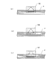
図10は、エアー吹出装置71におけるノズル73の開口形状の切り替えスペースを小スペースで実現するシート供給部(シート供給装置)の実施の形態を示す。尚、図10(a)はシート供給部のエアー吹出装置71部分を縦方向にて切断した断面説明図、同図(b)は(a)中B−B線断面図である。
同図において、シート供給部は、実施の形態1,2と同様に、シート供給トレイ59の側方にエアー吹出装置71を設け、このエアー吹出装置71のダクト72のエアー吹出し口にノズル73を設けたものであるが、このノズル73の構成が実施の形態1,2と異なっている。
【0041】
すなわち、本実施の形態において、ノズル73は、開口形状の異なる2枚のプレート201,202を重合配置した構造になっている。
ここで、プレート201はエアー吹出装置71のダクト72に固定されている。一方、プレート202はエアー吹出装置71の上部に設けられたレバー203にフィルム等の弾性部材204を介して連結されており、レバー203を操作することによりプレート201の表面を摺動するように取り付けられている。尚、プレート202はスプリング205にて常時下方向へ引っ張り付勢されているため、レバー203操作に連動して安定して摺動するようになっている。
また、レバー203はラッチ構造を有し、▲1▼と▲2▼の2ヶ所で保持されるようになっている。
【0042】
更に、本実施の形態では、プレート201の開口形状は、例えば図11(a)に示すように、幅が約40mm、高さが約20mmの長方形状であり、一方、プレート202の開口形状は、例えば図11(b)に示すように、プレート201の開口と同じ幅寸法を有しているが、開口上端部が上に凸となる三角形状に形成されて上方に向かって次第に狭くなるように構成され、かつ、開口下縁部がプレート201の開口と同一の幅寸法で切り欠かれている。
【0043】
更にまた、レバー203の操作については、手動は勿論のこと、シートの種類、環境条件等の情報取得手段により得られた情報を元に、ソレノイド、モータ等を用いて自動的に操作することも可能である。
【0044】
次に、本実施の形態に係るシート供給部の作動について説明する。
今、シートの種類や、環境条件等によってノズル73の開口形状を切り替える際には、レバー203を▲1▼又は▲2▼に移動させるようにすればよい。
このとき、レバー203を▲1▼の位置に設定した場合には、プレート201,202は図12(a)に示すように重合配置されるため、ノズル73の開口形状は長方形状になり、厚紙用などのノズル73として使用される。一方、レバー203を▲2▼の位置に設定した場合には、プレート201,202は図12(b)に示すように重合配置されるため、ノズル73の開口形状は開口上端部が次第に狭くなる形態になり、薄紙用などのノズル73として使用される。
このようなノズル73の開口形状の切り替えに当たっては、ノズル73の開口部2個分以下の上下スペースがあればよく、例えば図6に示すノズル73にあっては、ノズル73の開口形状を切り替える際に、ノズル73の開口部3個分のスペースの上下寸法を要することからすれば、ノズル73の開口形状の切り替えスペースを小スペースで実現することが可能である。
【0045】
また、レバー203位置を3ヶ所以上で保持できるようなラッチ構造を用いるようにすれば、切り替えられるノズル73の開口形状を3以上に設定することが可能である。
更に、ノズル73を複数ヶ所に具備させ、それらを全て同じ設定にする必要がある態様においては、ノズル73の開口形状の設定ミスを有効に防止するという観点からすれば、夫々のレバーを連結し、一つの操作で各レバーが一斉に操作できるような構成にすることが好ましい。
【0046】
【発明の効果】
以上説明したように、本発明によれば、エアー吹き付け手段を用いてシートを分離する際に、シートの種類、環境条件に応じて開口形状の異なるノズルを選択、交換することができるので、より広範なシートを安定して供給することが可能となる。
【図面の簡単な説明】
【図1】 (a)、(b)は、本発明に係るシート供給装置の概要を示す説明図である。
【図2】 実施の形態に係る画像形成装置の概要を示す説明図である。
【図3】 本実施の形態におけるシート供給部を説明するための斜視図である。
【図4】 本実施の形態におけるシート供給トレイの平面図である。
【図5】 本実施の形態におけるシート供給トレイを側面から示した概略説明図である。
【図6】 (a)、(b)は、本実施の形態におけるノズルの開口形状を示す説明図である。
【図7】 (a)、(b)は、本実施の形態における他のノズルの開口形状を示す説明図である。
【図8】 (a)、(b)、(c)は、実施の形態2における厚紙用のノズルを交換した状態を示すための説明図である。
【図9】 (a)、(b)、(c)は、実施の形態2における薄紙用のノズルを交換した状態を示すための説明図である。
【図10】 (a)は実施の形態3におけるシート供給部の概要を示す説明図、(b)は(a)中のB−B線断面図である。
【図11】 (a)(b)はノズルを構成する2枚のプレート構造を示す説明図である。
【図12】 (a)(b)はノズルの開口形状変化を示す説明図である。
【符号の説明】
1…シート収容手段、2…シート供給手段、3…ノズル、4…エアー吹き付け手段、5、6…開口、21…画像形成装置、31…画像書込装置、33…画像記録制御部、35…像担持体、37…帯電器、39…現像装置、43…転写ロール、45…定着装置、59…シート供給トレイ、60…シート供給部、61…引込ロール、62…搬送ロール、63…捌きロール、65…エンドガイド、67…側面固定式ガイド、69…側面可動式ガイド、71…エアー吹出装置、72…ダクト、73…ノズル、101…厚紙用の開口、102…薄紙用の開口、103…厚紙用の開口、104…薄紙用の開口、105、106、107、108、109、110…ノズル、201,202…プレート、203…レバー、204…弾性部材、205…スプリング、P…シート [0001]
BACKGROUND OF THE INVENTION
The present invention relates to a sheet feeding apparatus that feeds stacked sheets, and more particularly to a feeding apparatus that separates and feeds sheets having high adhesion between sheets.
[0002]
[Prior art]
In image forming apparatuses such as printers and copiers, generally, cut sheets that enable continuous paper feeding are used as media on which images are formed, and these sheets are conventionally designated by the copier manufacturer. Plain paper and high-quality paper were used. Since these sheets have low surface smoothness, the inter-sheet adhesion is low, and even when sheets are fed one by one from a sheet stacking unit such as a paper feed tray, multiple sheets are fed in close contact with each other. It was relatively easy to prevent. However, in recent years, with the diversification of recording media, it has become necessary to transport various types of sheets, including those with high surface smoothness. In particular, whiteness has increased as colorization technology has advanced. In addition to coated paper, glossy coated paper, OHP sheet, tracing paper, and the like, as well as thick paper with a particularly high basis weight, there is a high demand for conveyance by the same model. The coated paper, OHP sheet, tracing paper, and the like have strong adhesion between the sheets, so that it is difficult to prevent double feeding, and special measures are required for sheet supply.
[0003]
For example, a coated paper will be described as an example. As the coated paper becomes higher in quality, the coating amount increases and the white glossiness, which is an optical property, increases, and the surface roughness of the base paper decreases and the surface smoothness increases. Become. On the other hand, when the surface smoothness becomes high, the gap between the papers when they come into contact with each other becomes narrower, and the negative pressure generated in a state where air does not pass through the gap is maintained, and the adhesion between the sheets (between the sheets) is maintained. Become stronger. In particular, when smooth sheets such as coated paper are stacked in a high-humidity environment, the sheets are adsorbed and the degree of adhesion becomes higher. An OHP sheet or the like also has high surface smoothness and high adhesion between sheets.
[0004]
When such smooth sheets with strong adhesion between sheets are fed out one by one from the paper feed tray on which the sheets are stacked, they are separated and conveyed one by one with the normal plain paper feeding device. It becomes very difficult to do. In particular, a sheet feeding device using a pull-in roll that pulls a sheet by rotating in contact with the surface of the sheet with a predetermined pressing force, and a system that presses and separates a supply roll and a separation roll at a constant pressure when the sheet is rolled. Then, when the smooth sheet is separated and conveyed, a pressing force that is about 30 times that of normal plain paper is required. As a method for eliminating such adhesion to a smooth sheet in advance, the present applicant has proposed a technique for blowing air from the side surface of a stacked sheet in Japanese Patent Application Laid-Open No. 11-5643. According to this technique, a great effect can be achieved in eliminating the adhesion force in the smooth sheet.
[0005]
[Problems to be solved by the invention]
In this way, it is possible to dramatically improve the conveyance performance of the smooth sheet by feeding the air from the side of the paper and releasing the adhesion, but on the other hand, it is possible to raise the sheet easily and to separate the sheet. The problem is that the ease is not uniform depending on the type of sheet. That is, the sheet conveying apparatus using the air blowing means is characterized by releasing the close contact between the sheets by levitating the sheets. However, the ease of floating of the sheets and the ease of separation of the sheets are the close contact between the sheets. It is determined by the degree and rigidity. For example, a thin paper and a thick paper will be described as an example. A thin paper is easy to float by air but is difficult to separate. On the other hand, a thick paper is difficult to float but is easy to separate if it floats. As described above, it has been difficult to separate various sheets having different properties such as thin paper to thick paper by blowing air using the same device and floating the sheets.
[0006]
Furthermore, as a result of repeated studies by the inventors, it has been discovered that the state of sheet floating and separation differs depending on the environmental conditions in which the conveyed sheet is accommodated. For example, at a temperature of 28 ° C. and a humidity of 85%, 10 to 30 N is required to spread the adhered sheet, whereas at a temperature of 20 ° C. and a humidity of 55% and at a temperature of 10 ° C. and a humidity of 15%, it is spread at 5 to 10 N. It was possible. This result is the same even when the temperature is increased, and it is clear that the sheet adhesion is weak under low humidity and low humidity, and that the sheet adhesion is high under high humidity. The humidity greatly affects the sheet adhesion. It came to discover that.
[0007]
In order to solve the above technical problem, the sheet feeding apparatus according to the present invention has a sheet P as shown in FIGS. 1 (a) and 1 (b) ((b) is an AA sectional view of (a)). A
[0008]
If the air blowing means 4 is configured so that the
[0009]
In particular, the
Further, the
[0010]
The
[0011]
Still further, it is characterized by further comprising designation means for allowing the user who uses the sheet supply apparatus to designate the type of the sheet P, and selecting the
[0012]
Still further, the air blowing means 4 is configured such that the
[0013]
From the viewpoint of narrowing the switching space of the opening shape of the
In this aspect, the shape of the opening member may be appropriately selected such as a block or a plate, and the number of opening members may be two or more. Moreover, if the opening area | region of the
[0014]
Next, the operation of the technical means described above will be described.
Air blowing means 4 for blowing air from the side surface of the sheet P loaded on the sheet storing means 1 is provided, and the air blowing means 4 has different openings as shown in FIG.5, 6 shapesIs provided. The
[0015]
On the other hand, although it is easy to float from the stacked state as a feature of thin sheets, there are cases where a plurality of sheets P are in a floating state at the same time, and the plurality of sheets P are not yet separated in that state. . Therefore, an extremely strong lift is not required, but a certain lift is required even in a floating state. Therefore, when thin sheets are stacked, the opening shape shown in FIG.OpeningAn opening shape such as 6 can be selected. thisOpeningWhen an opening shape such as 6 is selected, even in a thin sheet in which two or more sheets are still bundled in a floating state, a predetermined lift acts in the floating state. As a result, even a thin sheet can be appropriately wound and supplied.
[0016]
DETAILED DESCRIPTION OF THE INVENTION
◎
Hereinafter, the present invention will be described in detail based on preferred embodiments shown in the accompanying drawings.
FIG. 2 shows an embodiment of an image forming apparatus to which the present invention is applied. In FIG. 1, an
[0017]
Furthermore, the
[0018]
FIG. 3 is a perspective view showing the
[0019]
The
[0020]
The pull-in
Further, the winding
[0021]
FIG. 4 is a plan view of the
[0022]
FIG. 5 is a schematic explanatory view showing the
[0023]
Coated paper with high adhesion between sheets in such a set state (composite sheet with a coating color applied as a kind of paint for the purpose of improving printability on both sides or one side of sheet P), basis weight When a thick cardboard or the like is transported, a plurality of sheets P are transported together and are transported downstream as a double feed.
At this time, an experiment by the inventor that the contact pressure on plain paper or copy paper would be very high if the contact pressure was simply increased to try to coat coated paper or cardboard. It became clear. Therefore, in the present embodiment, as one means for eliminating adhesion to the sheet P having high adhesion, such as coated paper, and in order to improve the supply performance with thick paper, an
[0024]
Here, a
[0025]
FIGS. 6A and 6B are explanatory views for explaining the opening shape of the
[0026]
The air blown out from the
[0027]
Next, when the sheet P is recognized as thick paper having a basis weight of about 200 gsm, for example, the user pushes down the
[0028]
The air blown out from the
[0029]
In the above description, the shape of the nozzle is simply changed depending on whether the sheet P is thin paper or thick paper, but in addition to this condition, the shape of the nozzle is based on environmental conditions such as humidity that has a strong influence on the degree of adhesion. It is also possible to configure to change. According to the study by the present inventors, the temperature of 28 ° C., which is the first zone, requires 10 to 30 N to roll the sheet P at the humidity of 85%, whereas the temperature of the second zone is 20 ° C. This is because it has become clear that it is possible to run at 5 to 10 N under a humidity of 55% and a temperature of 10 ° C. and a humidity of 15% as the third zone. As a result of conducting experiments in more detail based on this result, as the type of sheet P, in particular, with coated paper, there is almost no effect on the temperature condition, and the adhesion between the sheets is very high when the humidity is 60% or higher. On the contrary, when the humidity is 60% or less, which is low humidity, the adhesion between the sheets is weak. This tendency is the same for cardboard, and even simple cardboard is likely to float in a low humidity environment.
Therefore, when the normal sheet P is conveyed, the
[0030]
7A and 7B are diagrams in which the opening shape of the
[0031]
Further, in FIG. 7B, the opening shape of the
[0032]
Thus, according to the present embodiment, a wider range of sheets P can be stably supplied by switching the opening shape of the
[0033]
In the above description, the configuration that enables the user of the
[0034]
Further, for example, the switching of the
[0035]
◎
In the first embodiment, the
In addition, about the component similar to
[0036]
FIGS. 8A, 8B, and 8C show states in which the thick paper nozzles are respectively replaced. The
[0037]
These
[0038]
FIGS. 9A, 9B, and 9C show states in which the thin paper nozzles are respectively replaced. The
[0039]
These
[0040]
FIG. 10 shows an embodiment of a sheet supply unit (sheet supply device) that realizes a switching space for the opening shape of the
In the same figure, the sheet supply unit is provided with an
[0041]
That is, in the present embodiment, the
Here, the
The
[0042]
Furthermore, in the present embodiment, the opening shape of the
[0043]
Furthermore, the
[0044]
Next, the operation of the sheet supply unit according to the present embodiment will be described.
Now, when switching the opening shape of the
At this time, when the
In switching the opening shape of the
[0045]
If a latch structure that can hold the
Further, in an aspect in which the
[0046]
【The invention's effect】
As described above, according to the present invention, when separating sheets using air blowing means, depending on the type of sheet and environmental conditions.Nozzles with different opening shapesSince it can be selected and exchanged, a wider range of sheets can be stably supplied.
[Brief description of the drawings]
FIGS. 1A and 1B are explanatory views showing an outline of a sheet feeding apparatus according to the present invention.
FIG. 2 is an explanatory diagram showing an overview of an image forming apparatus according to an embodiment.
FIG. 3 is a perspective view for explaining a sheet supply unit in the present embodiment.
FIG. 4 is a plan view of a sheet supply tray in the present embodiment.
FIG. 5 is a schematic explanatory view showing a sheet supply tray from the side according to the present embodiment.
FIGS. 6A and 6B show the nozzle opening shape in the present embodiment.ShowIt is explanatory drawing.
FIGS. 7A and 7B show the opening shapes of other nozzles in the present embodiment.ShowIt is explanatory drawing.
FIGS. 8A, 8B, and 8C are explanatory diagrams for illustrating a state in which a thick paper nozzle in the second embodiment is replaced.
FIGS. 9A, 9B, and 9C are explanatory views for illustrating a state in which a thin paper nozzle in the second embodiment is replaced.
10A is an explanatory diagram showing an outline of a sheet supply unit in
FIGS. 11A and 11B are explanatory views showing a structure of two plates constituting a nozzle.
FIGS. 12A and 12B are explanatory diagrams showing changes in the shape of the nozzle opening. FIGS.
[Explanation of symbols]
DESCRIPTION OF
Claims (7)
前記シート収容手段からシートを供給するシート供給手段と、
前記シート収容手段に収容されたシートの端面に対向して開口されたノズルを有すると共に、当該ノズルからエアーを吹き付けるエアー吹き付け手段とを備え、
前記エアー吹き付け手段は、少なくとも上部の開口幅が狭まる開口を含む複数の異なる形状の開口が予め設定されたノズルを有し、所定の開口のノズルを選択または交換可能とし、かつ、シートに対するノズルの開口位置を固定配置するように構成されたことを特徴とするシート供給装置。Sheet storage means for storing the sheet;
Sheet supply means for supplying a sheet from the sheet storage means;
The nozzle having an opening facing the end face of the sheet accommodated in the sheet accommodating means, and air blowing means for blowing air from the nozzle,
The air blowing means includes a nozzle in which a plurality of differently shaped openings including at least an opening whose upper opening width is narrowed is set in advance, can select or replace a nozzle with a predetermined opening , A sheet feeding apparatus configured to fix and arrange an opening position.
前記指定手段による指定結果に基づいて前記ノズルを選択することを特徴とする請求項1記載のシート供給装置。The apparatus further comprises a designation unit that allows a user who uses the sheet feeding apparatus to designate the type of sheet,
The sheet feeding apparatus according to claim 1, wherein the nozzle is selected based on a designation result by the designation unit.
Priority Applications (1)
| Application Number | Priority Date | Filing Date | Title |
|---|---|---|---|
| JP34127499A JP3940876B2 (en) | 1999-07-19 | 1999-11-30 | Sheet feeding device |
Applications Claiming Priority (3)
| Application Number | Priority Date | Filing Date | Title |
|---|---|---|---|
| JP11-205342 | 1999-07-19 | ||
| JP20534299 | 1999-07-19 | ||
| JP34127499A JP3940876B2 (en) | 1999-07-19 | 1999-11-30 | Sheet feeding device |
Publications (3)
| Publication Number | Publication Date |
|---|---|
| JP2001088964A JP2001088964A (en) | 2001-04-03 |
| JP2001088964A5 JP2001088964A5 (en) | 2005-04-07 |
| JP3940876B2 true JP3940876B2 (en) | 2007-07-04 |
Family
ID=26515014
Family Applications (1)
| Application Number | Title | Priority Date | Filing Date |
|---|---|---|---|
| JP34127499A Expired - Fee Related JP3940876B2 (en) | 1999-07-19 | 1999-11-30 | Sheet feeding device |
Country Status (1)
| Country | Link |
|---|---|
| JP (1) | JP3940876B2 (en) |
Cited By (1)
| Publication number | Priority date | Publication date | Assignee | Title |
|---|---|---|---|---|
| US7744080B2 (en) | 2007-09-14 | 2010-06-29 | Ricoh Company, Ltd. | Sheet feed device and image forming apparatus |
Families Citing this family (11)
| Publication number | Priority date | Publication date | Assignee | Title |
|---|---|---|---|---|
| JP2003165641A (en) * | 2001-11-28 | 2003-06-10 | Fuji Xerox Co Ltd | Sheet feeder |
| JP4613782B2 (en) * | 2005-10-07 | 2011-01-19 | 富士ゼロックス株式会社 | Paper feeding device and image forming apparatus |
| JP4631695B2 (en) * | 2005-12-20 | 2011-02-16 | 富士ゼロックス株式会社 | Sheet supply apparatus and image forming apparatus |
| US7445205B2 (en) * | 2006-01-06 | 2008-11-04 | Xerox Corporation | Automatically variably heated airflow for separation of humid coated paper print media |
| JP5194830B2 (en) * | 2007-05-28 | 2013-05-08 | 株式会社リコー | Recording medium feeding device and image forming apparatus provided with the same |
| JP5194831B2 (en) * | 2007-09-04 | 2013-05-08 | 株式会社リコー | Recording medium feeding device and image forming apparatus provided with the same |
| US8141864B2 (en) | 2007-05-28 | 2012-03-27 | Ricoh Company, Limited | Recording-medium feeding device |
| CN101348196B (en) * | 2007-05-28 | 2012-06-27 | 株式会社理光 | Recording-medium feeding device |
| JP5058927B2 (en) * | 2008-09-22 | 2012-10-24 | 京セラドキュメントソリューションズ株式会社 | Paper feeding device and image forming apparatus having the same |
| JP2010202372A (en) * | 2009-03-04 | 2010-09-16 | Ricoh Co Ltd | Paper feeder and image forming device |
| JP5280383B2 (en) * | 2010-01-26 | 2013-09-04 | 富士フイルム株式会社 | Printing paper seasoning apparatus and method, and inkjet recording apparatus |
-
1999
- 1999-11-30 JP JP34127499A patent/JP3940876B2/en not_active Expired - Fee Related
Cited By (1)
| Publication number | Priority date | Publication date | Assignee | Title |
|---|---|---|---|---|
| US7744080B2 (en) | 2007-09-14 | 2010-06-29 | Ricoh Company, Ltd. | Sheet feed device and image forming apparatus |
Also Published As
| Publication number | Publication date |
|---|---|
| JP2001088964A (en) | 2001-04-03 |
Similar Documents
| Publication | Publication Date | Title |
|---|---|---|
| JP3940876B2 (en) | Sheet feeding device | |
| JP2006008380A (en) | Sheet feeder | |
| US10144599B2 (en) | Sheet feeding device and image forming apparatus incorporating the sheet feeding device | |
| JP2010111477A (en) | Recording material storing and processing device, post-processing device using the same, and recording material processing device | |
| JP4131325B2 (en) | Sheet supply apparatus and image forming apparatus | |
| JP2003165641A (en) | Sheet feeder | |
| US20060157914A1 (en) | Sheet feeding apparatus and image forming apparatus | |
| JP3854431B2 (en) | Sheet feeding device | |
| JP3891244B2 (en) | Sheet feeding device | |
| JP2006001699A (en) | Sheet feeder | |
| JP2006027797A (en) | Paper feeding device, and image forming device with the same | |
| JP2009078920A (en) | Media feeding device and image forming device | |
| JP4995668B2 (en) | Medium supply apparatus, image forming apparatus, and paper sheet processing apparatus | |
| JP4609264B2 (en) | Sheet feeding device | |
| JP2021120328A (en) | Sheet conveying device and image forming apparatus | |
| JP2000327174A (en) | Sheet feeding device and image forming device using it | |
| US5951005A (en) | Air corrugated stacking | |
| JP4862352B2 (en) | Recording medium discharge apparatus and image forming apparatus | |
| JP2001122490A (en) | Image forming device | |
| JP4692286B2 (en) | Sheet supply apparatus and image forming apparatus | |
| JP4400354B2 (en) | Sheet feeding device | |
| JP4600255B2 (en) | Image forming apparatus and paper feeding apparatus | |
| JP2007308285A (en) | Sheet supply apparatus and image forming apparatus | |
| JP7526380B2 (en) | SHEET STACKING DEVICE, POST-TREATING DEVICE, AND IMAGE FORMING SYSTEM | |
| JP4631695B2 (en) | Sheet supply apparatus and image forming apparatus |
Legal Events
| Date | Code | Title | Description |
|---|---|---|---|
| A521 | Written amendment |
Free format text: JAPANESE INTERMEDIATE CODE: A523 Effective date: 20040426 |
|
| A621 | Written request for application examination |
Free format text: JAPANESE INTERMEDIATE CODE: A621 Effective date: 20040426 |
|
| A977 | Report on retrieval |
Free format text: JAPANESE INTERMEDIATE CODE: A971007 Effective date: 20051205 |
|
| A131 | Notification of reasons for refusal |
Free format text: JAPANESE INTERMEDIATE CODE: A131 Effective date: 20051221 |
|
| A521 | Written amendment |
Free format text: JAPANESE INTERMEDIATE CODE: A523 Effective date: 20060209 |
|
| A131 | Notification of reasons for refusal |
Free format text: JAPANESE INTERMEDIATE CODE: A131 Effective date: 20060426 |
|
| A521 | Written amendment |
Free format text: JAPANESE INTERMEDIATE CODE: A523 Effective date: 20060626 |
|
| A02 | Decision of refusal |
Free format text: JAPANESE INTERMEDIATE CODE: A02 Effective date: 20060913 |
|
| A521 | Written amendment |
Free format text: JAPANESE INTERMEDIATE CODE: A523 Effective date: 20061108 |
|
| A911 | Transfer of reconsideration by examiner before appeal (zenchi) |
Free format text: JAPANESE INTERMEDIATE CODE: A911 Effective date: 20061121 |
|
| TRDD | Decision of grant or rejection written | ||
| A01 | Written decision to grant a patent or to grant a registration (utility model) |
Free format text: JAPANESE INTERMEDIATE CODE: A01 Effective date: 20070307 |
|
| A61 | First payment of annual fees (during grant procedure) |
Free format text: JAPANESE INTERMEDIATE CODE: A61 Effective date: 20070320 |
|
| R150 | Certificate of patent or registration of utility model |
Free format text: JAPANESE INTERMEDIATE CODE: R150 |
|
| FPAY | Renewal fee payment (event date is renewal date of database) |
Free format text: PAYMENT UNTIL: 20110413 Year of fee payment: 4 |
|
| FPAY | Renewal fee payment (event date is renewal date of database) |
Free format text: PAYMENT UNTIL: 20120413 Year of fee payment: 5 |
|
| FPAY | Renewal fee payment (event date is renewal date of database) |
Free format text: PAYMENT UNTIL: 20130413 Year of fee payment: 6 |
|
| FPAY | Renewal fee payment (event date is renewal date of database) |
Free format text: PAYMENT UNTIL: 20130413 Year of fee payment: 6 |
|
| FPAY | Renewal fee payment (event date is renewal date of database) |
Free format text: PAYMENT UNTIL: 20140413 Year of fee payment: 7 |
|
| LAPS | Cancellation because of no payment of annual fees |