JP3936142B2 - Blood component collection device - Google Patents
Blood component collection device Download PDFInfo
- Publication number
- JP3936142B2 JP3936142B2 JP2001027256A JP2001027256A JP3936142B2 JP 3936142 B2 JP3936142 B2 JP 3936142B2 JP 2001027256 A JP2001027256 A JP 2001027256A JP 2001027256 A JP2001027256 A JP 2001027256A JP 3936142 B2 JP3936142 B2 JP 3936142B2
- Authority
- JP
- Japan
- Prior art keywords
- collection
- blood
- platelet
- plasma
- platelet collection
- Prior art date
- Legal status (The legal status is an assumption and is not a legal conclusion. Google has not performed a legal analysis and makes no representation as to the accuracy of the status listed.)
- Expired - Fee Related
Links
Images


Classifications
-
- B—PERFORMING OPERATIONS; TRANSPORTING
- B04—CENTRIFUGAL APPARATUS OR MACHINES FOR CARRYING-OUT PHYSICAL OR CHEMICAL PROCESSES
- B04B—CENTRIFUGES
- B04B5/00—Other centrifuges
- B04B5/04—Radial chamber apparatus for separating predominantly liquid mixtures, e.g. butyrometers
- B04B5/0442—Radial chamber apparatus for separating predominantly liquid mixtures, e.g. butyrometers with means for adding or withdrawing liquid substances during the centrifugation, e.g. continuous centrifugation
- B04B2005/0464—Radial chamber apparatus for separating predominantly liquid mixtures, e.g. butyrometers with means for adding or withdrawing liquid substances during the centrifugation, e.g. continuous centrifugation with hollow or massive core in centrifuge bowl
Landscapes
- Medical Preparation Storing Or Oral Administration Devices (AREA)
- External Artificial Organs (AREA)
- Centrifugal Separators (AREA)
Description
【0001】
【発明の属する技術分野】
本発明は、血液中から所定の血液成分を分離する血液成分採取装置に関する。
【0002】
【従来の技術】
採血を行う場合、現在では、血液の有効利用および供血者の負担軽減などの理由から、採血血液を遠心分離などにより各血液成分に分離し、輸血者に必要な成分だけを採取し、その他の成分は供血者に返還する成分採血が行われている。
このような成分採血において、血小板製剤を得る場合、供血者から採血した血液を血液成分採取回路に導入し、該血液成分採取回路に設置された遠心ボウルと呼ばれる遠心分離器により、血漿、白血球、血小板および赤血球の4成分に分離し、その内の血小板を容器に回収して血小板製剤とし、血漿を容器に回収して血漿製剤もしくは血漿分画製剤の原料とし、残りの白血球および赤血球は、供血者に返血することが行われる。
【0003】
血小板採取方法として、例えば、特表平8−509403号公報に開示されている方法がある。この特表平8−509403号公報には、液体を全血に既定流速で加えて希釈しながら遠心ボウルに送るという第1の方式、遠心ボウルに全血を送り込み、遠心分離して低密度成分、中密度成分および高密度成分に分離し、低密度成分を第一の容器に取り出した後、回路を切り替えてその低密度成分を第一流速(定速)で循環させて遠心ボウル内の中密度成分領域を広げ、第二流速(加速)で再循環している間に中密度成分を取り出すという第2の方式が開示されている。そして、この血液成分採取装置では、血小板採取終了タイミングを遠心分離器の流出口付近のラインに取り付けられたラインセンサ(濁度センサ)により検知される信号の変化を利用して行っている。正常状態の場合、血小板採取時における濁度センサにより検知される信号の変化パターンは、図9に示すように、濁度センサ基準値より急激に降下し変曲点(下限ピーク)より再び上昇し、基準値より低い値にて再び変曲点を有する。特表平8−509403号の血液成分採取装置では、このパターンを利用して、血小板採取終了タイミングを決めている。
しかし、本発明者が多くの採血例について検討したところ、濁度センサにより検知される信号の変化パターンは、上記のような正常パターンのみではなく、複数の例外パターンが存在することがわかった。これは、供血者の血液性状(ヘマトクリット値)のバラツキまたは供血者の血流状態のバラツキによって生じるものと考える。このような例外パターンの場合に、正常パターンを想定した判断において血小板採取終了タイミングを決めると、目標とする血小板採取数に到達しない場合や、逆に血小板をより多く採取し同時に採取したくない白血球や赤血球まで採取してしまう場合などが発生する。
【0004】
【発明が解決しようとする課題】
ヘマトクリット値の低い供血者や低い採血流量の供血者であっても、白血球や赤血球の混入が少ない良好な血小板含有血漿の採取を行うことができる血液成分採取装置を提供する。
【0005】
【課題を解決するための手段】
上記目的を達成するものは、内部に貯血空間を有する遠心分離器により血液を複数の血液成分に分離し、特定の血液成分をバッグに採取するための血液成分採取装置であって、該血液成分採取装置は、採血手段と前記遠心分離器の流入口とを接続するための第1のラインと、前記遠心分離器の流出口に接続された第2のラインと、前記第1のラインの途中に接続された第1チューブおよび前記第2のラインと接続された第2チューブを有する血漿採取バッグと、前記第2のラインに接続された血小板採取バッグとからなる血液成分採取回路と、前記遠心分離器の流出口もしくは前記第2のラインに取り付けられた濁度センサと、血小板採取時に、前記濁度センサにより検知される信号および該信号より算出される信号変化パターンを利用して、血小板採取過程が、記憶している正常パターンもしくは複数の例外パターンのいずれかであるか判断する血小板採取過程パターン判断機能と、血小板採取過程パターン判断機能により判断されたパターンに適した時点において、血小板採取ステップを終了させる血小板採取ステップ終了時調整機能と、前記血小板採取過程パターン判断機能により、複数の例外パターンのうちのいずれかであると判断された場合に、次回の血小板採取ステップにおける血小板採取条件を血小板採取ステップ時における濁度センサにより検知される信号の変化パターンが、記憶している正常パターンに近づくように、血小板採取条件を調整する血小板採取条件調整機能とを備える血液成分採取装置である。
【0006】
そして、前記血小板採取過程パターン判断機能は、前記血小板採取ステップ時において、前記濁度センサにより検知される信号および該信号より算出される信号変化パターンならびに血小板採取時の循環速度を利用して、血小板採取過程が、記憶している正常パターンもしくは複数の例外パターンのいずれかであるか判断するものであることが好ましい。
【0007】
また、前記血液成分採取回路は、前記第1のラインに接続された抗凝固剤注入のための第3のラインを備え、前記血液成分採取装置は、前記遠心分離器のローターを回転させるための遠心分離器駆動装置と、前記第1のラインと前記第1チューブとの接続部より遠心分離器側に配置され、前記第1のラインのための第1の送液ポンプと、前記第3のラインのための第2の送液ポンプと、前記血液成分採取回路の流路の開閉を行うための複数の流路開閉手段と、前記遠心分離器駆動装置、前記第1の送液ポンプ、前記第2の送液ポンプおよび前記複数の流路開閉手段を制御するための制御部を備え、該制御部は、抗凝固剤が添加された血液の採取、採取された血液の分離および分離された血漿を前記血漿採取バッグ内に採取する血漿採取ステップと、該血漿採取ステップにより採取された前記血漿採取バッグ内の血漿を前記遠心分離器に循環させる血漿循環ステップとからなる少なくとも1回の血漿採取・循環ステップと、該血漿採取・循環ステップの終了後に、前記第1の送液ポンプによる血漿循環速度を加速させて、前記遠心分離器内より血小板を流出させ血小板を前記血小板採取バッグに採取する血小板採取ステップを行わせ、該血小板採取ステップの終了後、前記遠心分離器内の血液を返血する返血ステップを行わせる血小板採取操作が行われるように、前記遠心分離器駆動装置、前記第1の送液ポンプ、前記第2の送液ポンプおよび前記複数の流路開閉手段を制御するものであり、かつ、前記血小板採取過程パターン判断機能および前記血小板採取終了時調整機能を備えているものであることが好ましい。
【0008】
そして、前記制御部は、前記血小板採取操作が少なくとも2回行われるように、前記遠心分離器駆動装置、前記第1の送液ポンプ、前記第2の送液ポンプおよび前記複数の流路開閉手段を制御するものであることが好ましい。また、前記制御部は、前記血漿採取・循環ステップの終了後であって、前記第1の送液ポンプによる血漿循環速度を加速させる前に、前記第1の送液ポンプ、第2の送液ポンプを作動させて抗凝固剤が添加された血液を採取し、前記遠心分離器駆動装置を作動させて、血液より前記血漿採取バッグ内に所定量の血漿を採取する血漿採取ステップを行わせるものであることが好ましい。さらに、前記制御部は、前記血漿採取・循環ステップが2回行われるように制御するものであり、初回の血漿採取・循環ステップでは、前記血漿採取バッグ内の血漿を前記遠心分離器に定速にて循環させる血漿採取・定速循環ステップが行われ、2回目の血漿採取・循環ステップでは、前記血漿採取バッグ内の血漿を前記遠心分離器に加速させながら循環させる血漿採取・加速循環ステップが行われるように制御するものであることが好ましい。
【0009】
また、前記血液成分採取回路は、前記第2のラインに接続されたバフィーコート採取バッグを備え、前記制御部は、前記血小板採取ステップ終了後であって、前記返血ステップ前に、前記遠心分離器内よりバフィーコートを流出させバフィーコートを前記バフィーコート採取バッグに採取するバフィーコート採取ステップを行うものであることが好ましい。
さらに、前記制御部は、前記バフィーコート採取ステップの終了後さらに血小板採取操作が行われる場合には、採取されたバフィーコートを次の血漿採取・循環ステップ前に前記遠心分離器内に返還するバフィーコート返還ステップを行わせるように、前記第1の送液ポンプおよび前記複数の流路開閉手段を制御するものであることが好ましい。
【0010】
そして、前記血小板採取装置は、抗凝固剤が添加された血液の採取、採取された血液の分離および分離された血漿を前記血漿採取バッグ内に採取する血漿採取ステップと、該血漿採取ステップにより採取された前記血漿採取バッグ内の血漿を前記遠心分離器に循環させる血漿循環ステップとからなる少なくとも1回の血漿採取・循環ステップと、該血漿採取・循環ステップの終了後に、前記第1の送液ポンプによる血漿循環速度を加速させて、前記遠心分離器内より血小板を流出させ血小板を前記血小板採取バッグに採取する血小板採取ステップを行わせ、該血小板採取ステップの終了後、前記遠心分離器内の血液を返血する返血ステップを行わせる血小板採取操作が少なくとも2回行われるよう制御する機能を備えていることが好ましい。
【0011】
そして、前記血小板採取過程パターン判断機能は、前記血小板採取ステップ時において、前記濁度センサにより検知される信号および該信号より算出される信号変化パターンならびに血小板採取時の循環速度を利用して、血小板採取過程が、記憶している正常パターンもしくは複数の例外パターンのいずれかであるか判断するものであり、さらに、前記血漿採取装置は、初回の血小板採取過程が正常パターンであると判断した場合に、当該初回血小板採取過程に関するデータを記憶する初回血小板採取過程データ記憶部と、次回以降の血小板採取ステップにおける血小板採取過程におけるデータを前記初回血小板採取過程データと比較するためのデータ比較機能を有し、前記血小板採取ステップ終了時調整機能は、前記データ比較機能により初回血小板採取過程データと比較対象血小板採取過程データ間に所定以上の相違が検出された場合に血小板採取ステップを終了させる機能を有するものであることが好ましい。
さらに、前記血液成分採取装置は、前記データ比較機能により初回血小板採取過程データと比較対象血小板採取過程データ間に所定以上の相違が検出された場合に作動する警告機能を備えていることが好ましい。
【0012】
そして、前記制御部は、第1回目の血小板採取操作時における前記血小板採取ステップ開始から前記濁度センサによる下限ピーク電圧検出までのピーク時間の計測および記憶ならびに下限ピーク電圧の記憶機能と、第2回目以降の血小板採取操作時における血小板採取ステップ開始から前記ピーク時間到達時における前記濁度センサ電圧と前記下限ピーク電圧との差が所定値より大きいかどうか比較する比較機能を有し、前記血小板採取ステップ終了時調整機能は、該比較機能により前記第2回目以降の血小板採取操作時における血小板採取ステップ開始から前記ピーク時間到達時における前記濁度センサ電圧と前記下限ピーク電圧との差が所定値より大きいことが判断された場合に、所定秒間における濁度センサ電圧変化率を演算し、演算された電圧変化率が所定値より小さい場合に血小板採取ステップを終了させるものであることが好ましい。
さらに、前記制御部の前記血小板採取ステップ終了時調整機能は、電圧変化率演算機能により演算された前記所定秒間における電圧変化率が前記所定値より大きい場合に、再度電圧変化率演算機能により所定秒間における第2の電圧変化率を演算させ、演算された第2の電圧変化率が所定値より小さい場合に血小板採取ステップを終了させるものであることが好ましい。
【0013】
また、本発明の目的を達成するものは、内部に貯血空間を有する遠心分離器により血液を複数の血液成分に分離し、特定の血液成分をバッグに採取するための血液成分採取装置であって、該血液成分採取装置は、採血手段と前記遠心分離器の流入口とを接続するための第1のラインと、前記遠心分離器の流出口に接続された第2のラインと、前記第1のラインの途中に接続された第1チューブおよび前記第2のラインと接続された第2チューブを有する血漿採取バッグと、前記第2のラインに接続された血小板採取バッグとからなる血液成分採取回路と、前記遠心分離器の流出口もしくは前記第2のラインに取り付けられた濁度センサと、前記遠心分離器のローターを回転させるための遠心分離器駆動装置と制御部を備え、該制御部は、抗凝固剤が添加された血液の採取、採取された血液の分離および分離された血漿を前記血漿採取バッグ内に採取する血漿採取ステップと、該血漿採取ステップにより採取された前記血漿採取バッグ内の血漿を前記遠心分離器に循環させる血漿循環ステップとからなる少なくとも1回の血漿採取・循環ステップと、該血漿採取・循環ステップの終了後に、前記第1の送液ポンプによる血漿循環速度を加速させて、前記遠心分離器内より血小板を流出させ血小板を前記血小板採取バッグに採取する血小板採取ステップを行わせ、該血小板採取ステップの終了後、前記遠心分離器内の血液を返血する返血ステップを行わせる血小板採取操作が少なくとも2回行われるように制御するものであり、さらに、該制御部は、第1回目の血小板採取操作時における前記血小板採取ステップ開始から前記濁度センサによる下限ピーク検出までのピーク時間の計測および記憶ならびに当該下限ピーク電圧の記憶機能と、第2回目以降の血小板採取操作時における血小板採取ステップ開始から前記ピーク時間到達時における前記濁度センサ電圧と前記下限ピーク電圧との差が所定値より大きいかどうか比較する比較機能と、該比較機能により前記第2回目以降の血小板採取操作時における血小板採取ステップ開始から前記ピーク時間到達時における前記濁度センサ電圧と前記下限ピーク電圧との差が所定値より大きいことが判断された場合に、所定秒間における濁度センサ電圧変化率を演算する電圧変化率演算機能と、該電圧変化率演算機能により演算された電圧変化率が所定値より小さい場合に血小板採取ステップを終了させる血小板採取ステップ終了時調整機能を備えている血液成分採取装置である。そして、前記制御部の前記血小板採取ステップ終了時調整機能は、電圧変化率演算機能により演算された前記所定秒間における電圧変化率が前記所定値より大きい場合に、再度電圧変化率演算機能により所定秒間における第2の電圧変化率を演算させ、演算された第2の電圧変化率が所定値より小さい場合に血小板採取ステップを終了させるものであることが好ましい。
【0014】
【発明の実施の形態】
本発明の血液成分採取装置を図面に示した実施例を用いて説明する。
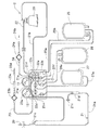
図1は、本発明の血液成分採取装置に使用される血液成分採取回路の構成例を示す平面図であり、図2は、図1の血液成分採取回路のカセットハウジング部分の平面図であり、図3は、血液成分採取回路に使用される遠心分離器に駆動装置が装着された状態の部分破断断面図であり、図4は、血液成分採取回路を装着した状態の本発明の血液成分採取装置の一実施例の概念図である。
本発明の血液成分採取装置1は、内部に貯血空間を有する遠心分離器20により血液を複数の血液成分に分離し、特定の血液成分をバッグに採取するための血液成分採取装置である。血液成分採取装置1には、採血手段(採血針29もしくは血液プールへの接続部)と遠心分離器20の流入口とを接続するための第1のライン21と、遠心分離器20の流出口に接続された第2のライン22と、第1のラインの途中に接続された第1チューブ25aおよび第2のラインと接続された第2チューブ25bを有する血漿採取バッグ25と、第2のラインに接続された血小板採取バッグ26とからなる血液成分採取回路2が装着される。血液成分採取装置1は、遠心分離器20の流出口もしくは第2のラインに取り付けられた濁度センサ14と、血小板採取時に、濁度センサにより検知される信号およびこの信号より算出される信号変化パターンを利用して、血小板採取過程が記憶している正常パターンもしくは複数の例外パターンのいずれかであるか判断する血小板採取過程パターン判断機能と、血小板採取過程パターン判断機能により判断されたパターンに適した時点において、血小板採取ステップを終了させる血小板採取ステップ終了時調整機能を備えている。
【0015】
血液成分採取装置1は、内部に貯血空間を有するローター142と、貯血空間に連通する流入口143および流出口144とを有し、ローター142の回転により流入口143より導入された血液を貯血空間内で遠心分離する遠心分離器20と、採血針29もしくは血液プールへの接続部と遠心分離器20の流入口143とを接続するための第1のライン21と、遠心分離器20の流出口144に接続された第2のライン22と、第1のライン21に接続され、抗凝固剤注入のための第3のライン23と、第1のライン21に接続された第1チューブ25aおよび第2のライン22と接続された第2チューブ25bを有する血漿採取バッグ25と、第2のライン22に接続された血小板採取バッグ26とを備える血液成分採取回路2のための血液成分採取装置である。
血液成分採取装置1は、遠心分離器20のローター142を回転させるための遠心分離器駆動装置10と、第1のライン21のための第1の送液ポンプ11と、第3のライン23のための第2の送液ポンプ12と、血液成分採取回路2の流路の開閉を行うための複数の流路開閉手段81,82,83,84,85,86,87と、遠心分離器駆動装置10、第1の送液ポンプ11、第2の送液ポンプ12および複数の流路開閉手段を制御するための制御部13を備える。
この血液成分採取装置は、2つのポンプにより構成されているので、装置が小型化できる。
【0016】
そこで、最初に血液成分採取回路2について説明する。
この血液成分採取回路2は、血液成分、特に血小板を採取するための回路である。血小板採取回路2は、採血針29のような採血器具、もしくは採血針または血液プール接続部を有する採血器具への接続部(採血器具接続部)、採血針29もしくは採血器具接続部と遠心分離器20の流入口143とを接続し、第1のポンプチューブ21gを備える第1のライン21(採血および返血ライン)、遠心分離器20の流出口144と第1のライン21とを接続するための第2のライン22、第1のライン21の採血針29の近くに接続され、第2のポンプチューブ23aを備える第3のライン23(抗凝固剤注入ライン)、第1のライン21のポンプチューブ21gより採血針側に位置する分岐コネクター21fに接続された第1チューブ25aおよび第2のライン22と接続された第2チューブ25bを有する血漿採取バッグ25、第2のライン22に接続された第3チューブ26aを備える血小板採取バッグ26、第2のライン22に接続された第4チューブ27aを備えるバフィーコート採取バッグ27、第2のライン22に接続された液体(生理食塩水)注入用の第4のライン24を備える。血液成分採取回路2としては、採血針ではなく、血液バッグなどの血液プールに接続するための接続部(例えば、金属もしくは合成樹脂針)を備えるものでもよい。
【0017】
採血針29として、公知の金属針が使用される。第1のライン21は、採血針29が接続された採血針側第1ライン21aと遠心分離器20の流入口143とを接続された遠心分離器側第1ライン21bとからなる。採血針側第1ライン21aは、軟質樹脂製チューブが複数接続されて形成されている。採血針側第1ライン21aは、採血針側より、第3のライン23との接続用分岐コネクター21c、気泡およびマイクロアグリゲート除去のためのチャンバー21d、第2のライン22との接続用分岐コネクター21e、血漿採取バッグ25の第1チューブ25aとの接続用分岐コネクター21fを備える。チャンバー21dには、通気性かつ菌不透過性のフィルター21iが接続されている。遠心分離器側第1ライン21bは、第1チューブ25aとの接続用分岐コネクター21fに接続されており、その付近に形成されたポンプチューブ21gを有する。
【0018】
遠心分離器20の流出口144と第1のライン21とを接続する第2のライン22は、一端が遠心分離器20の流出口144に接続され、他端が第1のライン21の接続用分岐コネクター21eに接続されている。第2のライン22は、遠心分離器側から、血漿採取バッグ25の第2チューブ25bならびに血小板採取バッグ26の第3チューブ26aとの接続用分岐コネクター22a、第4のライン24との接続用分岐コネクター22b、気泡除去用フィルター22fを備えるチューブとの接続用分岐コネクター22c、バフィーコート採取バッグ27の第4チューブ27aとの接続用分岐コネクター22dを備える。
第3のライン23は、一端が第1のライン21に設けられた接続用分岐コネクター21cに接続されている。第3のライン23は、コネクター21c側より、ポンプチューブ23a、異物除去用フィルター23b、気泡除去用チャンバー23c、抗凝固剤容器接続用針23dを備えている。
第4のライン24は、一端が第2のライン22の接続用分岐コネクター22bに接続されている。第4のライン24は、コネクター22b側より、異物除去用フィルター24a、生理食塩水容器接続用針24bを備えている。
【0019】
血漿採取バッグ25は、第1のライン21のポンプチューブ21gより採血針側に位置する分岐コネクター21fに接続された第1チューブ25a、第2のライン22の分岐コネクター22aに接続された第2チューブ25bを有する。血小板採取バッグ26は、第2のライン22の分岐コネクター22aに接続された第3チューブ26aを備える。バフィーコート採取バッグ27は、第2のライン22の分岐コネクター22dに接続された第4チューブ27aを備える。
上述した第1から第4のライン21,22,23,24の形成に使用されるチューブ、ポンプチューブ、さらに、バッグに接続されているチューブの構成材料としては、例えば、ポリ塩化ビニル、ポリエチレン、ポリプロピレン、PETやPBTのようなポリエステル、エチレン−酢酸ビニル共重合体、ポリウレタン、ポリエステルエラストマー、スチレン−ブタジエン−スチレン共重合体等の熱可塑性エラストマー等が挙げられるが、その中でも特に、ポリ塩化ビニルが好ましい。各チューブがポリ塩化ビニル製であれば、十分な可撓性、柔軟性が得られるので取り扱いがし易く、また、クレンメ等による閉塞にも適するからである。また、上述した分岐コネクターの構成材料についても、前記チューブの構成材料と同様のものを用いることができる。なお、ポンプチューブとしては、ローラーポンプにより押圧されても損傷を受けない程度の強度を備えるものが使用されている。
【0020】
血漿採取バッグ25、血小板採取バッグ26、バフィーコート採取バッグ27は、それぞれ、樹脂製の可撓性を有するシート材を重ね、その周縁部を融着(熱融着、高周波融着等)または接着して袋状にしたものが使用される。各バッグ25,26,27に使用される材料としては、例えば、軟質ポリ塩化ビニルが好適に使用される。この軟質ポリ塩化ビニルにおける可塑剤としては、例えば、ジ(エチルヘキシル)フタレート(DEHP)、ジ−(n−デシル)フタレート(DnDP)等が使用される。なお、このような可塑剤の含有量は、ポリ塩化ビニル100重量部に対し、30〜70重量部程度とするのが好ましい。
また、上記各バッグ25,26,27のシート材料としては、ポリオレフィン、すなわちエチレン、プロピレン、ブタジエン、イソプレン等のオレフィンあるいはジオレフィンを重合または共重合した重合体を用いてもよい。具体的には、例えば、ポリエチレン、ポリプロピレン、エチレン−酢酸ビニル共重合体(EVA)、EVAと各種熱可塑性エラストマーとのポリマーブレンド等、あるいは、これらを任意に組み合わせたものが挙げられる。さらには、ポリエチレンテレフタレート(PET)、ポリブチレンテレフタレート(PBT)、ポリ−1,4−シクロヘキサンジメチルテレフタレート(PCHT)のようなポリエステル、ポリ塩化ビニリデンを用いることもできる。
【0021】
なお、血小板採取バッグ26に使用されるシート材としては、血小板保存性を向上するためにガス透過性に優れるものを用いることがより好ましい。そのようなシート材としては、例えば、上述したポリオレフィンやDnDP可塑化ポリ塩化ビニル等を用いること、また、このような素材を用いることなく、上述したような材料のシート材を用い、厚さを比較的薄く(例えば、0.1〜0.5mm程度、特に、0.1〜0.3mm程度)したものが好適である。また、血小板採取バッグには、例えば、生理食塩水、GAC、PAS、PSM−1のような血小板保存液があらかじめ入れられていてもよい。
【0022】
そして、血液成分採取回路2の主要部分は、図2に示すように、カセット式となっている。血液成分採取回路2は、すべてのライン(第1のライン、第2のライン、第3のライン、第4のライン)およびすべてのチューブ(第1チューブ、第2チューブ、第3チューブ、第4チューブ)を部分的に収納しかつ部分的にそれらを保持し、言い換えれば、部分的にそれらが固定されたカセットハウジング28を備える。カセットハウジング28には、第1のポンプチューブ21gの両端および第2のポンプチューブ23aの両端が固定され、これらポンプチューブ21g,23aは、カセットハウジング28より、ローラーポンプの形状に対応したループ状に突出している。このため、第1および第2のポンプチューブ21g,23aは、ローラーポンプへの装着が容易である。
【0023】
さらに、カセットハウジング28は、カセットハウジング28内に位置する複数の開口部を備えている。具体的には、ポンプチューブ21gより採血針側部分の第1のライン21を露出させかつ、血液成分採取装置1の第1の流路開閉手段81の侵入が可能な第1の開口部91、血漿採取バッグ25の第1チューブ25aを露出させかつ血液成分採取装置1の第2の流路開閉手段82の侵入が可能な第2の開口部92、血漿採取バッグ25の第2チューブ25bを露出させかつ血液成分採取装置1の第3の流路開閉手段83の侵入が可能な第3の開口部93、血小板採取バッグ26の第3チューブ26aを露出させかつ血液成分採取装置1の第4の流路開閉手段84の侵入が可能な第4の開口部94、第2のライン22とバフィーコート採取バッグ27の第4チューブ27aとの接続部より遠心分離器側(上流側)の位置の第2のライン22を露出させかつ血液成分採取装置1の第5の流路開閉手段85の侵入が可能な第5の開口部95、第1のライン21との接続部とバフィーコート採取バッグ27の第4チューブ27aとの接続部との間(第2のライン22と第4チューブ27aとの接続部より下流側)の第2のライン22を露出させかつ血液成分採取装置1の第6の流路開閉手段86の侵入が可能な第6の開口部96、第4のライン24を露出させかつ血液成分採取装置1の第7の流路開閉手段87の侵入が可能な第7の開口部97を備えている。
【0024】
また、カセットハウジング28の内面には、上述した分岐コネクターが固定されている。さらに、カセットハウジング28の側面付近には、ハウジングの側面より突出するラインおよびチューブを保持し、かつハウジング部分での折れ曲がりを防止するための補強チューブが設けられている。カセットハウジング28は、内部に図2において破線で示す部分を収納可能な箱状体となっている。そして、カセットハウジング28は、ある程度の剛性を有する合成樹脂により形成されている。
血液成分採取装置1は、このカセットハウジング装着部(図示せず)を備えている。このため、カセットハウジング28を血液成分採取装置1のカセットハウジング装着部に装着することにより、カセットハウジング28の開口部より露出する部分の各ラインおよび各チューブが、自動的に対応する流路開閉手段に装着される。これにより回路の装着が容易であるとともに、血液成分採取準備も迅速に行われる。また、血液成分採取装置1には、カセットハウジング装着部に近接して2つのポンプが設けられている。このため、カセットハウジング28より露出するポンプチューブのポンプへの装着も容易である。
【0025】
血液成分採取回路2に設けられている遠心分離器20は、通常遠心ボウルと呼ばれており、遠心力により血液成分を分離する。遠心分離器20は、図3に示すように、上端に流入口143が形成された鉛直方向に伸びる管体141と、管体141の周りで回転し、上部145に対し液密にシールされた中空のローター142とで構成されている。ローター142には、その底部および周壁内面に沿って流路(貯血空間)が形成され、この流路の上部に連通するように流出口144が形成されている。この場合、ローター142の容積は、例えば、100〜350ml程度とされる。
ローター142は、血液成分採取装置1が備えるローター回転駆動装置10によりあらかじめ設定された所定の遠心条件(回転速度および回転時間)で回転される。この遠心条件により、ローター142内の血液の分離パターン(例えば、分離する血液成分数)を設定することができる。本実施例では、図3に示すように、血液がローター142の流路内で内層より血漿層131、バフィーコート層132および赤血球層133に分離されるように遠心条件が設定される。
【0026】
次に、図4に示す本発明の血液成分採取装置1について説明する。
血液成分採取装置1は、遠心分離器20のローター142を回転させるための遠心分離器駆動装置10と、第1のライン21のための第1の送液ポンプ11と、第3のライン23のための第2の送液ポンプ12と、血液成分採取回路2の流路の開閉を行うための複数の流路開閉手段81,82,83,84,85,86,87と、遠心分離器駆動装置10、第1の送液ポンプ11、第2の送液ポンプ12および複数の流路開閉手段を制御するための制御部13を備える。さらに、血液成分採取装置1は、第2チューブ25bとの接続部22aより遠心分離器側(上流側)の第2のライン22に装着される濁度センサ14、遠心分離器20の上方に取り付けられた光学式センサ15と、血漿採取バッグ25の重量を検知するための重量センサ16を備える。
また、流路開閉手段81,82,83,84,85,86,87も、すべて制御部13に接続され、それらの開閉は制御部13により制御されている。さらに、濁度センサ14、遠心分離器20の上方に取り付けられた光学式センサ15、血漿採取バッグ25の重量を検知するための重量センサ16も、制御部13と電気的に接続され、それらより出力される信号は制御部13に入力される。制御部13は、例えばマイクロコンピュータで構成される制御機構およびローター回転数演算機能を有し、上述した重量センサ16、光学式センサ15、濁度センサ14からの検出信号は、制御部13へ随時入力される。制御部13は、濁度センサ14、光学式センサ15、重量センサ16からの信号に基づき、各ポンプの回転、停止、回転方向(正転/逆転)を制御するとともに、必要に応じ、各流路開閉手段の開閉および遠心分離器回転駆動装置10の作動(ローターの回転)を制御する。
【0027】
第1の流路開閉手段81は、ポンプチューブ21gより採血針側において第1のライン21を開閉するために設けられている。第2の流路開閉手段82は、血漿採取バッグ25の第1チューブ25aを開閉するために設けられている。第3の流路開閉手段83は、血漿採取バッグ25の第2チューブ25bを開閉するために設けられている。第4の流路開閉手段84は、血小板採取バッグ26の第3チューブ26aを開閉するために設けられている。第5の流路開閉手段85は、第2のライン22とバフィーコート採取バッグ27の第4チューブ27aとの接続部22dより遠心分離器側(上流側)の位置にて、第2のライン22を開閉するために設けられている。第6の流路開閉手段86は、第1のライン21との接続部21eと第4チューブ27aとの接続部との間(第2のライン22と第4チューブ27aとの接続部より下流側)の位置にて、第2のライン22を開閉するために設けられている。第7の流路開閉手段87は、第4のライン24を開閉するために設けられている。流路開閉手段は、ラインもしくはチューブの挿入部を備え、挿入部には、例えば、ソレノイド、電動モータ、シリンダ(油圧または空気圧)等の駆動源で作動するクランプを有する。具体的には、空気圧で作動する空圧シリンダクランプが好適である。流路開閉手段のクランプは、制御部13からの信号に基づいて作動する。
【0028】
ローター駆動装置10は、図3に示すように、遠心分離器20を収納するローター回転駆動装置ハウジング151と、脚部152と、駆動源であるモータ153と、遠心分離器20を保持する円盤状の固定台155とで構成されている。ハウジング151は、脚部152の上部に載置、固定されている。また、ハウジング151の下面には、ボルト156によりスペーサー157を介してモータ153が固定されている。モータ153の回転軸154の先端部には、固定台155が回転軸154と同軸でかつ一体的に回転するように嵌入されており、固定台155の上部には、ローター142の底部が嵌合する凹部が形成されている。また、遠心分離器20の上部145は、図示しない固定部材によりハウジング151に固定されている。ローター回転駆動装置10では、モータ153を駆動すると、固定台155およびそれに固定されたローター142が、例えば、回転数3000〜6000rpmで回転する。
【0029】
また、ローター回転駆動装置ハウジング151の内壁には、遠心分離器内の分離された血液成分の界面(例えば、血漿層131とバフィーコート層132との界面B、バフィーコート層132と赤血球層133との界面)の位置を光学的に検出する光学式センサ(界面センサ)15が、取付部材158により設置、固定されている。この界面センサ15としては、遠心分離器20の外周面に沿って上下方向に走査し得る光学式センサが用いられる。このセンサは、遠心分離器20の肩の部分に向けて光を照射する光源と、遠心ボウルから反射して戻ってくる光を受光する受光部で構成されている。つまり、LEDまたはレーザーのような発光素子と受光素子とが列状に配置され、発光素子から発せられた光の血液成分での反射光を受光素子により受光し、その受光光量を光電変換するように構成されている。分離された血液成分(例えば、血漿層131とバフィーコート層132)により反射光の強度が異なるため、受光光量が変化した受光素子に対応する位置が、界面Bの位置として検出される。より具体的には、遠心分離器20の光が通過する位置が透明な液体(血漿や水)で充填されている時と、バフィーコート層で充填されている時の、受光部での受光量の差から、バフィーコート層が光通過部に到達したことが検知される。バフィーコート層を検出する位置は、光がボウル内を通過する位置を変えることで調節され、通常は、光線通過位置を決めたら、そこで固定する。
【0030】
濁度センサ14は、第2のライン22中を流れる流体の濁度を検知するためのものであり、濁度に応じた電圧値を出力する。具体的には、濁度が高い時には低電圧値、濁度が低い時には高電圧値を出力する。
第1のライン21のポンプチューブ21gが装着される第1の送液ポンプ11ならびに第3のライン23のポンプチューブ23aが装着される第2の送液ポンプ12としては、ローラーポンプ、ペリスタリックポンプなどの非血液接触型ポンプが好適である。また、第1の送液ポンプ11(血液ポンプ)としては、いずれの方向にも血液を送ることができるものが使用される。具体的には、正回転と逆回転が可能なローラーポンプが用いられている。
【0031】
制御部13は、抗凝固剤が添加された血液の採取、採取された血液の分離および分離された血漿を血漿採取バッグ内に採取する血漿採取ステップと、この血漿採取ステップにより採取された血漿採取バッグ内の血漿を遠心分離器に循環させる血漿循環ステップとからなる少なくとも1回の血漿採取・循環ステップと、この血漿採取・循環ステップの終了後に、第1の送液ポンプによる血漿循環速度を加速させて、遠心分離器内より血小板を流出させ血小板を血小板採取バッグに採取する血小板採取ステップと、この血小板採取ステップの終了後、遠心分離器内の血液を返血する返血ステップを行わせるものである。
具体的には、制御部13は、第1の送液ポンプ11、第2の送液ポンプ12を作動させて抗凝固剤が添加された血液を採取し、遠心分離器駆動装置10を作動させて(上述した演算値もしくは設定値にて、ローターを回転させて)、血液より血漿採取バッグ25内に第1の所定量の血漿を採取する第1の血漿採取ステップを行わせ、次に、採血を一時中断し、かつ、遠心分離器駆動装置10を作動させて(上述した演算値もしくは設定値にて、ローターを回転させて)、血漿採取バッグ内の血漿を遠心分離器20に定速にて循環させる定速血漿循環ステップ(定速サーキュレーション)からなる血漿採取・定速循環ステップを行わせ、次に、第1の送液ポンプ11、第2の送液ポンプ12を作動させて抗凝固剤が添加された血液を採取し、遠心分離器駆動装置10を作動させて(上述した演算値もしくは設定値にて、ローターを回転させて)、界面センサにより所定位置(例えば、バフィーコート層)を検出するまで血漿を採取する第2の血漿採取ステップと、この第2の血漿採取ステップ終了後に、採血を一時中断し、かつ、遠心分離器駆動装置10を作動させて(上述した演算値もしくは設定値にて、ローターを回転させて)、血漿採取バッグ25内の血漿を遠心分離器20に加速させながら循環させる加速血漿循環ステップ(加速サーキュレーション)とからなる血漿採取・加速循環ステップ、この血漿採取・循環ステップの終了後に、第1の送液ポンプ11による血漿循環速度を加速させて、遠心分離器20内より血小板を流出させ血小板を血小板採取バッグに採取する血小板採取ステップと、この血小板採取ステップの終了後、遠心分離器20内の血液を返血する返血ステップを行わせるものである。なお、第2の血漿採取ステップでは、界面センサで検出するため、血漿バッグの重量検知を行わない。
【0032】
このように、1回の血小板採取操作中に、採血を一時中止しそして採取された血漿を遠心分離器に再循環する血漿再循環ステップが少なくとも2回行われ、かつ、後半の血漿再循環ステップが加速循環となっているため、遠心分離器内での血球層、バフィーコート層(BC層)が過剰圧縮されることを抑制し、赤血球層に埋もれた血小板を舞上げ、BC層に取り込むことができる。また、BC層自体も舞い上がるため、BC層内の血小板と白血球との分離と整列を促進する。このため、白血球の混入が少なく、かつ血小板の採取効率も高い血小板含有液(濃厚血小板血漿)を得ることができる。
【0033】
さらに、この実施例の血液成分採取装置1の制御部13は、上述した血漿採取・定速循環ステップ、血漿採取・加速循環ステップ、血小板採取ステップ、返血ステップからなる血小板採取操作が2回行われるように、遠心分離器駆動装置10、第1の送液ポンプ11、第2の送液ポンプ12および複数の流路開閉手段を制御するものである。
さらに、この実施例の血液成分採取装置1の制御部13は、血小板採取ステップ終了後であって、返血ステップ前に、第1の送液ポンプ11による血漿循環速度を血小板採取ステップにおける最終速度よりも高くし、遠心分離器20内よりバフィーコートを流出させバフィーコートをバフィーコート採取バッグ27に採取するバフィーコート採取ステップを行うように制御する。なお、バフィーコート採取ステップは、上記の方法に限定されるものではなく、例えば、第1の送液ポンプ11による血漿循環速度を血小板採取ステップにおける最終速度を維持し、かつ、遠心分離器20のローターの回転速度を下げることにより行ってもよい。さらに、バフィーコート採取ステップは、第1の送液ポンプによる血漿循環速度を血小板採取ステップにおける最終速度より高くするとともに、遠心分離器のローターの回転速度を下げることにより行ってもよい。
【0034】
そして、バフィーコート採取ステップの終了後、採取されたバフィーコートを次の採血ステップの前に遠心分離器20内に返還するバフィーコート返還ステップを行わせるように、第1の送液ポンプ11および複数の流路開閉手段を制御する。
そして、制御部13は、血小板採取ステップ時において、濁度センサ14により検知される信号およびこの信号より算出される信号変化パターンより、血小板採取過程が、記憶している正常パターンもしくは複数の例外パターンのいずれかであるか判断する血小板採取過程パターン判断機能と、血小板採取過程パターン判断機能により判断されたパターンに適した時点において、血小板採取ステップを終了させる血小板採取ステップ終了時調整機能を備えている。特に、この実施例の血液成分採取装置の制御部13では、血小板採取ステップ時において、濁度センサ14により検知される信号、経時的に入力される濁度センサ14により検知される信号より算出できる信号変化の傾き、血小板採取ステップ時における循環速度を利用して、血小板採取過程が、記憶している正常パターンもしくは複数(具体的には、A〜Eの5つ)の例外パターンのいずれかであるか判断する血小板採取過程パターン判断機能を備えている。そして、各パターンに適した時点において、血小板採取ステップを終了させる。
【0035】
本発明の血液成分採取装置は、上述した濁度センサ14と、濁度センサ14の電圧信号を制御部13の演算ユニットに変換伝達するためのアナログ/デジタル変換器(図示せず)を備え、制御部13は、信号処理するための演算ユニット、信号データの記憶およびパターン認識、判断を実行するプログラムの記憶のためのRAM、ROM等の記憶ユニットを備える。
図5ないし図10は、血小板採取時における濁度センサにより検知される信号の変化パターンを示す図である。図5は、血小板採取時における濁度センサにより検知される信号の正常な変化パターンを示す図である。図6は、血小板採取時における濁度センサにより検知される信号の例外パターンの1例(例外パターンA)を示す図である。図7は、血小板採取時における濁度センサにより検知される信号の例外パターンの他の例(例外パターンB)を示す図である。図8は、血小板採取時における濁度センサにより検知される信号の例外パターンの他の例(例外パターンC)を示す図である。図9は、血小板採取時における濁度センサにより検知される信号の例外パターンの他の例(例外パターンD)を示す図である。図10は、血小板採取時における濁度センサにより検知される信号の例外パターンの他の例(例外パターンE)を示す図である。
血小板が流出している状態では濁度センサ14の信号は時間と共に増加または減少を示す変化をしており、微小な時間間隔(1/1000秒〜2秒、好ましくは1/100秒〜1秒)での信号変化を見ると、血小板流出が開始した時点では「−」の傾きであり、血小板流出がピークを迎えた辺りでその傾きは「0」となる。その後血小板流出は徐々に減少するため傾きは「+」に変化する。血小板の流出が完全に終了するか、または白血球や赤血球の流出が始まるとこの傾きが再び「0」から「−」に変化する。従って、制御部13では、信号変化パターン判断は、この傾きを用いて行う。
【0036】
そして、制御部13は、信号変化パターン判断機能により判断されたパターンに適した時点において、血小板採取ステップを終了させる。
具体的には、図5に示す正常変化パターンでは、血小板流出開始とともに電圧が急激に低下し、赤血球検出電圧に到達しないところで下限ピークを迎え、今度は急激に電圧が上昇し、終了電圧を越える。正常パターンでは、傾きの変化は、血小板採取開始→「−」→「0」→「+」→「0」となる。そして、このようなパターンを取り、かつ、血小板採取が開始された時点の循環速度が200ml/min未満であれば、正常パターンであり、終了電圧に到達した時に、血小板採取を終了させる。
【0037】
また、図6に示す例外パターンの1例(例外パターンA)では、濁度センサ電圧が所定値Xに到達せず、血小板流出開始とともに電圧が徐々に低下し続けるというケースである。このパターンは、血小板は流出するが流出量が極めて少ない状態であり、目標血小板採取数に到達しない恐れのあるパターンである。この例外パターンAでは、傾きの変化は、血小板採取開始→「−」となる。このような例外パターンAの場合には、血小板濃度(PC濃度)が所定量(例えば、100万)に到達しない状態(濁度センサ電圧が所定値Xに到達しない)にて、血小板採取量が設定量に到達した時点において、血小板採取を終了させる。ここで終了させる理由は、血小板の流出量が極めて少なく、血小板採取量を増やしても、目標血小板数を採取できないためである。
【0038】
図7に示す例外パターンBでは、血小板流出開始とともに電圧が急激に低下し、赤血球検出電圧を越えても下限ピークを迎えず、電圧低下が継続するというケースである。このパターンは血小板採取条件が大幅にズレてしまい、白血球や赤血球が流出を始める状況を示すものである。例外パターンBでは、傾きの変化は、血小板採取開始→「−」となる。
このような例外パターンBの場合には、血小板濃度(PC濃度)が所定量(例えば、100万)に到達した状態(濁度センサ電圧が所定値Xに到達した)後、濁度センサ電圧が赤血球検出電圧に到達した時点において、血小板採取を終了させる。これにより、赤血球の混入を防止できる。
【0039】
図8に示す例外パターンCでは、血小板流出開始とともに電圧が急激に低下し、赤血球検出電圧を越えることはないものの継続して電圧低下するというケースである。このパターンは、パターンA程血小板の流出は少なくないものの、本来流出すべき値よりも少ない状況である。目標採取血小板数には達するものの血小板採取条件としてはまだ不十分なケースである。例外パターンCでは、傾きの変化は、血小板採取開始→「−」となる。
このような例外パターンCの場合には、血小板濃度(PC濃度)が所定量(例えば、100万)に到達した状態(濁度センサ電圧が所定値Xに到達した)後、濁度センサ電圧が赤血球検出電圧に到達せず、かつ、電圧の下限ピークを得ることなく、血小板採取量が設定量に到達した時点において、血小板採取を終了させる。ここで終了させる理由は、血小板の流出量が少なくなってきており、このまま血小板を採取し続けると、バッグ内の血小板濃度が低くなるためである。
【0040】
図9に示す例外パターンDでは、血小板流出開始とともに電圧が急激に低下し、下限ピークを迎えた後、電圧は上昇するものの終了電圧に到達しないというケースである。このパターンは、パターンA程血小板の流出は少なくないものの、本来流出すべき値よりも少ない状況である。目標血小板採取数には達するものの血小板採取条件としてはまだ不十分なケースである。例外パターンDでは、傾きの変化は、血小板採取開始→「−」→「0」→「+」となる。
このような例外パターンDの場合には、血小板濃度(PC濃度)が所定量(例えば、100万)に到達した状態(濁度センサ電圧が所定値Xに到達した)後、濁度センサ電圧が赤血球検出電圧に到達せず、かつ、電圧の下限ピークを得た後、濁度センサ電圧が終了電圧に到達することなく、血小板採取量が設定量に到達した時点において、血小板採取を終了させる。ここで終了させる理由は、電圧の下限ピークを得ており、ある程度の血小板数を確保しているが、このまま血小板採取を続けても、採取効率が悪くなるため(終了電圧に達するまで時間がかかり、バッグ内の血小板濃度が低くなるため)である。
【0041】
図10に示す例外パターンEでは、血小板流出開始とともに電圧が急激に低下し、赤血球検出電圧に到達しないところで下限ピークを迎え、今度は急激に電圧が上昇し、終了電圧を越えることなく、再び電圧の低下がするというケースである。このパターンでは、傾きの変化は、血小板採取開始→「−」→「0」→「+」→「0」→「−」となる。このケースでは、電圧の傾きの変化が、終了電圧に到達することなく、「−」となった時点にて、血小板採取を終了させる。このパターンEは、供給される血小板があまり多くなく、血小板流出に引き続いて白血球や赤血球の流出が生じるケースである。
以上述べたように濁度センサの信号を時間経過と共に解析する手法と濁度センサでの検出信号を組み合わせることなどによって、白血球や赤血球が流出する前に血小板採取を終了させることができる。
【0042】
さらに、制御部13は、血小板採取過程パターン判断機能により、例外パターンであると判断された場合に、次回の血小板採取ステップにおける血小板採取条件を調整する血小板採取条件調整機能を備えていることが好ましい。そして、制御部13の血小板採取条件調整機能は、血小板採取過程パターン判断機能により、複数の例外パターンのうちのいずれかであると判断した場合に、次回の血小板採取ステップにおける血小板採取条件を判断した例外パターンに適した条件に血小板採取条件を調整するものであることが好ましい。特に、血小板採取条件調整機能は、血小板採取ステップ時における濁度センサにより検知される信号の変化パターンが、記憶している正常パターンに近づくように、血小板採取条件を調整するものであることが好ましい。
【0043】
具体的には、血小板採取が終了した時点においては次のサイクルでの血小板採取条件を決定するため、そのサイクルでの血小板採取パターンから微調整すべきパラメータ[実際には第二血小板採取操作(次回血小板採取ステップ)]終了のためのBC界面センサの検出タイミング)の微調整量を自動選択(微調整量は事前に流出パターンに対応してテーブル値として設定しておく)させる。つまり、判断されたパターンに応じて、次回の血小板採取操作(血小板採取ステップ)終了のためのセンサ15によるBC界面の検出タイミングを変更させる。
より具体的には、図6に示すような例外パターンAの場合には、BC界面の検出設定を下げる。BC界面の検出設定を下げるということは、採血量を増やして、遠心ボウル内のBC界面位置を流出口方向に上げるための操作を示し、具体的にはBC界面センサの検出値(受光率%)を上げることである。BC界面の検出設定(検出率)の下げ幅としては、0.5〜5%程度が好ましく、より好ましくは、1〜2%程度である。
また、BC界面を下げることにより、濁度センサ14の信号変化が正常パターンに近づくので、血小板の採取効率が向上する。
【0044】
また、図7に示すような例外パターンBの場合には、BC界面の検出設定を上げる。BC界面を上げるということは、遠心ボウル内に供給する血液量を減らして(採血量を減らして)、遠心ボウル内のBC界面位置を流入口方向に下げるための操作を示し、BC界面センサの検出値(受光率%)を上げることである。BC界面の検出設定(検出率)の下げ幅としては、0.5〜5%程度が好ましく、より好ましくは、1〜2%程度である。
このように、BC界面を上げることにより、濁度センサ14の信号変化が正常パターンに近づくので、血小板の採取効率が向上する。
【0045】
また、図8に示す例外パターンCおよび図9に示す例外パターンDの場合には、BC界面の検出設定を下げる。BC界面の検出設定の下げ幅としては、0.5〜5%程度が好ましく、より好ましくは、1〜2%程度である。また、下げ幅は、血小板採取時の濁度センサの信号電圧(最終電圧)により調整することが好ましい。つまり、最終電圧が所定値より低い場合は、所定値より高い場合より、下げ幅を大きくすることが好ましい。
このようにBC界面を下げることにより、濁度センサ14の信号変化が正常パターンに近づくので、血小板の採取効率が向上する。
【0046】
また、図10に示す例外パターンEの場合には、BC界面の検出設定を上げる。
上げ幅は、血小板採取時の循環速度により調整することが好ましい。つまり、終了時の循環速度が、所定値(例えば、130ml/min)以下の場合は、所定値より高い場合より、上げ幅を大きくすることが好ましい。さらに、終了時の循環速度が、第2の所定値(例えば、200ml/min)以上の場合には、BC界面の検出設定変更を行わないものとしてもよい。
このようにBC界面を上げることにより、濁度センサ14の信号変化が正常パターンに近づくので、血小板の採取効率が向上する。
上記のように、調整することにより、血小板採取ステップ時における濁度センサにより検知される信号の変化パターンが、記憶している正常パターンに近づくようになる。
【0047】
また、供血者の中には、血小板採取が進む毎に血小板流出が減少する傾向を示す者がいる。このような供血者の場合には、2回目以降の血小板採取ステップ時に血小板流出のピークを示すことなく、血球流出に至るケースがある。そこで、正常であった第1回目の血小板採取操作時の血小板採取ステップにおけるデータを記憶させ、第2回目以降の血小板採取操作時の血小板採取ステップにおけるデータと比較し、両者間に所定値以上の差異がある場合に血小板採取を中断することにより、血球混入を防止するものである。
このために、制御部は、前記血小板採取ステップ時において、前記濁度センサにより検知される信号および該信号より算出される信号変化パターンならびに血小板採取時の循環速度を利用して、血小板採取過程が、記憶している正常パターンもしくは複数の例外パターンのいずれかであるか判断するものであり、さらに、血小板採取過程パターン判断機能は、初回の血小板採取過程が正常パターンであると判断した場合に、初回血小板採取ステップにおけるデータを記憶する初回血小板採取過程データ記憶部と、次回以降の血小板採取ステップにおける血小板採取過程におけるデータを前記初回血小板採取過程データと比較するためのデータ比較機能を有し、さらに、制御部の血小板採取ステップ終了時調整機能は、上記のデータ比較機能により初回血小板採取過程データと比較対象回の血小板採取過程データ間に所定以上の相違が検出された場合に血小板採取ステップを終了させる機能を有することが好ましい。
【0048】
さらに、血液成分採取装置は、上記のデータ比較機能により初回血小板採取過程データと比較対象回の血小板採取過程データ間に所定以上の相違が検出された場合に作動する警告機能を備えていることが好ましい。
具体的には、制御部は、第1回目の血小板採取操作時における前記血小板採取ステップ開始から前記濁度センサによる下限ピーク電圧検出までのピーク時間の計測および記憶ならびに下限ピーク電圧の記憶機能と、第2回目以降の血小板採取操作時における血小板採取ステップ開始から前記ピーク時間到達時における前記濁度センサ電圧と前記下限ピーク電圧との差が所定値より大きいかどうか比較する比較機能を有する。さらに、制御部は、血小板採取ステップ終了時調整機能の一部として、上記比較機能により第2回目以降の血小板採取操作時における血小板採取ステップ開始から上記ピーク時間到達時における濁度センサ電圧と第1回目の下限ピーク電圧との差が所定値より大きいことが判断された場合に、所定秒間における濁度センサ電圧変化率を演算し、演算された電圧変化率が所定値より小さい場合に血小板採取ステップを終了させるものである。
【0049】
そして、制御部の前記血小板採取ステップ終了時調整機能は、電圧変化率演算機能により演算された前記所定秒間における電圧変化率が前記所定値より大きい場合に、再度電圧変化率演算機能により所定秒間における第2の電圧変化率を演算させ、演算された第2の電圧変化率が所定値より小さい場合に血小板採取ステップを終了させるものであることが好ましい。さらに、血液成分採取装置は、前記データ比較機能により初回血小板採取過程データと比較対象血小板採取過程データ間に所定以上の相違が検出された場合に作動する警告機能を備えていることが好ましい。具体的には、演算された第2の電圧変化率が所定値より小さい場合に作動する警告機能を備えていることが好ましい。
具体的には、この血小板採取装置は、以下のような血小板採取ステップ終了時調整機能を備える。
【0050】
まず、第1回目の血小板採取操作時の血小板採取ステップにおける血小板採取開始から血小板流出ピークまでの時間(ピーク時間:Tpeek1)と濁度センサによるピーク電圧(Vpeek1)の計測および記憶を行う。そして、第2回目以降の血小板採取操作時の血小板採取ステップにおいて、血小板採取開始から第1回目のピーク時間(Tpeek1)到達時の濁度センサ電圧(V2)を記憶する。そして、濁度センサにより下限ピークが検出されていない場合には、V2が、Vpeek1+所定値(言い換えれば、許容値、例えば、0.1〜1.0v)より大きいかどうか比較する。言い換えれば、V2−Vpeek1が、所定値(許容値)より大きいかどうかを比較する。そして、差が、所定値より大きい場合には、「異常傾向あり」と判断する。
【0051】
そして、「異常傾向あり」の場合、所定秒間における濁度センサ電圧の変化率もしくは変化量を用いて、血小板採取ステップを終了するかどうかの判断を行う。具体的には、一定時間経過後(例えば、1〜5秒程度)における濁度センサ電圧(V2a)と第1回目のピーク時間(Tpeek1)到達時の濁度センサ電圧(V2)より所定時間(所定秒間)における濁度センサ電圧変化率を演算し、この濁度センサ電圧変化率が第1の許容値(例えば、−0.5〜+0.5v)より大きいかどうかを判断する。そして、濁度センサ電圧変化率が第1の許容値以下の場合には、血小板採取ステップを終了させる。また、濁度センサ電圧変化率が第1の許容値より大きい場合には、再度一定時間経過後(例えば、1〜5秒程度)における濁度センサ電圧(V2b)と上記の濁度センサ電圧(V2a)より所定時間(所定秒間)における濁度センサ電圧変化率を演算し、この濁度センサ電圧変化率が第2の許容値(例えば、−0.5〜+0.5v)より大きいかどうかを判断する。そして、濁度センサ電圧変化率が第2の許容値以下の場合には、血小板採取ステップを終了させる。また、濁度センサ電圧変化率が第2の許容値より大きい場合には、通常プログラムに戻り、血小板採取ステップを継続する。
このように、2回目以降の血漿採取操作時の血小板採取ステップにおいて、第1回目の血小板流出に関するデータを用いて、2回目以降の血小板採取ステップにおける状況を判断し、異常な状態の場合には、血小板採取ステップを終了させることにより、血球混入の少ない血小板採取を行うことができる。
なお、上記の機能は、血小板採取過程パターン判断機能およびその判断機能に基づいた血小板採取ステップ終了時調整機能を備えない血小板採取装置にも有効である。
【0052】
そのような血小板採取装置は、内部に貯血空間を有する遠心分離器により血液を複数の血液成分に分離し、特定の血液成分をバッグに採取するための血液成分採取装置であって、血液成分採取装置は、採血手段と前記遠心分離器の流入口とを接続するための第1のラインと、前記遠心分離器の流出口に接続された第2のラインと、前記第1のラインの途中に接続された第1チューブおよび前記第2のラインと接続された第2チューブを有する血漿採取バッグと、前記第2のラインに接続された血小板採取バッグとからなる血液成分採取回路と、前記遠心分離器の流出口もしくは前記第2のラインに取り付けられた濁度センサと、前記遠心分離器のローターを回転させるための遠心分離器駆動装置と制御部を備え、該制御部は、抗凝固剤が添加された血液の採取、採取された血液の分離および分離された血漿を前記血漿採取バッグ内に採取する血漿採取ステップと、該血漿採取ステップにより採取された前記血漿採取バッグ内の血漿を前記遠心分離器に循環させる血漿循環ステップとからなる少なくとも1回の血漿採取・循環ステップと、該血漿採取・循環ステップの終了後に、前記第1の送液ポンプによる血漿循環速度を加速させて、前記遠心分離器内より血小板を流出させ血小板を前記血小板採取バッグに採取する血小板採取ステップを行わせ、該血小板採取ステップの終了後、前記遠心分離器内の血液を返血する返血ステップを行わせる血小板採取操作が少なくとも2回行われるように制御するものであり、さらに、該制御部は、第1回目の血小板採取操作時における前記血小板採取ステップ開始から前記濁度センサによる下限ピーク検出までのピーク時間の計測および記憶ならびに当該下限ピーク電圧の記憶機能と、第2回目以降の血小板採取操作時における血小板採取ステップ開始から前記ピーク時間到達時における前記濁度センサ電圧と前記下限ピーク電圧との差が所定値より大きいかどうか比較する比較機能と、該比較機能により前記第2回目以降の血小板採取操作時における血小板採取ステップ開始から前記ピーク時間到達時における前記濁度センサ電圧と前記下限ピーク電圧との差が所定値より大きいことが判断された場合に、所定秒間における濁度センサ電圧変化率を演算する電圧変化率演算機能と、該電圧変化率演算機能により演算された電圧変化率が所定値より小さい場合に血小板採取ステップを終了させる血小板採取ステップ終了時調整機能を備えている。
なお、この血小板採取装置および血液成分採取装置としては、上述の血小板採取過程パターン判断機能およびその判断機能に基づく、血小板採取ステップ終了時調整機能を備えない以外は、上述したものと同じである。
【0053】
血小板採取操作をより具体的に説明する。
全血に抗凝固剤を所定(全血に対して、1/8〜1/20、具体的には1/10)比率で加え、所定速度(250ml/min以下;好ましくは、150から40ml/min以下、具体的には、60ml/min以下)で第1のライン21を介して遠心分離器20に送り、遠心分離器20を所定回転数(3000〜6000rpm、好ましくは、4400〜5800rpmの範囲で回転させて血液を血漿、バフィーコート、赤血球の各成分に分離し、血漿が遠心分離器20をオーバーフローしたら血漿バッグに採取し、血漿を所定量(10〜150ml、好ましくは、20〜30ml)採取した時点で送血を停止して、血漿を所定条件(採血量よりも大きい速度であり、60〜250ml/minで10〜90sec、具体的には、第1循環が200ml/min×30sec)で、第1のライン21および第2のライン22を通して遠心分離器20に戻す、定速血漿循環を行う。
【0054】
そして、再び、全血に抗凝固剤を所定(全血に対して、1/8〜1/20、具体的には1/10)比率で加え、所定速度(250ml/min以下;好ましくは、150〜40ml/min以下、具体的には、60ml/min以下)で第1のライン21を介して遠心分離器20に送り、遠心分離器20を所定回転数(3000〜6000rpm、好ましくは、4700〜4800rpm)で回転させて血液を血漿、バフィーコート、赤血球の各成分に分離し、遠心分離器20内部の血球界面位置をバフィーコート界面検出センサにて検出した時点で送血を停止して、血漿を所定条件(初速60〜80ml/min、最終到達速度(設定速度)150〜250 ml/min、加速条件(1秒間毎に)2〜10ml/minの速度上昇、循環時間10〜90sec)で、第1のライン21および第2のライン22を通して遠心分離器20に戻す、加速血漿循環を行う。
最後の採血が行われた後、血漿を所定条件で第1および第2のライン22を通して遠心分離器20に戻し、所定条件にて段階的に加速度を上昇させて(ステップワイズな加速;0.1〜99ml/min/sec,具体的には、2〜10ml/min/sec)血小板採取速度(60〜250ml/min)に到達させ、遠心分離器20より、流出してきた血小板を血小板採取バッグ26に採取するものである。特に、本発明の血液成分採取装置では、濁度センサ14により検知される信号およびこの信号より算出される信号変化パターンより、血小板採取過程が、記憶している正常パターンもしくは複数の例外パターンのいずれかであるか判断し、判断されたパターンに適した時点において、血小板採取ステップが終了する。
【0055】
さらに、この装置では、血小板採取後、血液循環速度を維持(60〜250ml/min、具体的には、200ml/min)し、かつ、遠心分離器20の回転数を下げる(今までの回転数より、100〜300rpm程度下げる)ことにより、流出してきたバフィーコートを採取し、次のサイクルの採血を行う前に、採取したバフィーコートを遠心分離器20に供給するようになっている。なお、バフィーコートの採取は、血小板採取後、血液循環速度を所定速度(血小板採取速度以上、好ましくは、60〜250ml/min、具体的には、205ml/min)に加速することにより行ってもよい。
【0056】
この実施例の血液成分採取装置4による血液成分採取工程(第1回目の血小板採取操作)を図11ないし図20のフローチャートを用いて説明する。この実施例では、血小板採取操作を繰り返して2回行い、さらに、最終回以外の血小板採取ステップ終了後であって、返血ステップ前に、バフィーコート採取ステップを行いかつ次の採血ステップの前に遠心分離器20にこれを返還するバフィーコート返還ステップを行うようになっている。なお、第7の流路開閉手段87は閉じた状態とし、流体注入用の第4のライン24は使用されない。
まず、最初に、第3のライン23と採血針29を抗凝固剤でプライミングし、その後ドナーに穿刺針を穿刺する。
そして、遠心分離器駆動装置10はローターを回転させて、血液より血漿採取バッグ25内に第1の所定量の血漿を採取する第1の血漿採取ステップを行う。
【0057】
最初の採血が開始されると、血液ポンプ11が所定速度(例えば、60ml/min)で採血を開始する。このとき、抗凝固剤ポンプである第2のポンプも同時に所定速度(例えば、血液ポンプ速度の1/10)で抗凝固剤(例えば、ACD−A液)を供給する。ドナーから採取された血液はACD−A液と混合され、第1のライン21を流れ、チャンバー、第1の流路開閉手段81を通過し、遠心分離器20に流入する。このとき、第6の流路開閉手段86、第5の流路開閉手段85、第2の流路開閉手段82,第3の流路開閉手段83は閉じており、第1の流路開閉手段81、第4の流路開閉手段84は開いている。遠心分離器20にACD−A液添加血液(ACD加血液)が供給されると、遠心分離器20に入っていた滅菌空気は第2のライン22を流れ、第4の流路開閉手段84を通過し、血小板採取バッグ26内に流入する。採血工程開始と同時に遠心分離器20が所定速度で回転を開始し、遠心分離器20は回転しながらACD加血液の供給を受けるので、分離器内では血液の遠心分離が行われ、血液は、内側から血漿層、バフィーコート層(BC層)、赤血球層の3層に分離され、分離器の容量を越えるACD加血液(約270ml)が供給されると、遠心分離器20内は完全に血液により満たされ、遠心分離器20の流出口から血漿が流出する。遠心分離器20の流出口と接続された第2のライン22に取り付けられた濁度センサ14は、ライン中を流れる流体が、空気から血漿に変わったことを検知し、制御部13は、この濁度センサ14の検知信号に基づき第4の流路開閉手段84を閉塞させ、かつ第3の流路開閉手段83を開放させて、血漿を血漿採取バッグ25内に採取する。血漿採取バッグ25は、その重量が重量センサ16により計測されており、計測された重量信号は制御部13に入力されている。このため、血漿採取バッグ25に採取された血漿重量が第1の所定量(10〜150g、例えば、30g)増加すると、制御部13は、第1の流路開閉手段81を閉塞させ、第2の流路開閉手段82を開放させて、定速血漿循環ステップに移行する。
【0058】
定速血漿循環ステップでは、採血を一時中断し、かつ、遠心分離器駆動装置10を作動させて、血漿採取バッグ25内に採取された血漿を遠心分離器20に定速にて循環させる。
定速血漿循環ステップに入ると、制御部13は、第1の流路開閉手段81の閉塞状態および第2の流路開閉手段82の開放状態を維持し、ACDポンプ12は停止し、血液ポンプ11は所定速度(60〜250ml/min、例えば、200ml/min)で作動し、血漿採取バッグ25の血漿は第2の流路開閉手段82を通って、所定速度で回転する遠心分離器20に送られる。同時に遠心分離器20から流出してきた血漿は濁度センサ14、第3の流路開閉手段83を通って血漿採取バッグ25に流入する。定速血漿循環ステップが始まって所定時間(10〜90秒、例えば、30秒)が経過すると、制御部13は、第2の流路開閉手段82を閉じ、第1の流路開閉手段81を開いて、第2の血漿採取ステップに移行する。第1の血漿循環は、少なくとも60ml/min以上の流速で、10秒以上行うことが好ましい。
【0059】
第2の血漿採取ステップでは、第1の送液ポンプ11、第2の送液ポンプ12を作動させて抗凝固剤が添加された血液を採取し、通常、バッグ内の血漿量の増加により、光学式センサ15が、分離器のバフィーコート層を検出すると、この信号が制御部13に送られ、制御部13は、第1の流路開閉手段81を閉塞させ、第2の流路開閉手段82を開放させて、加速血漿循環ステップに移行する。
具体的には、第1の送液ポンプ11が所定速度(例えば、60ml/min)で採血を開始する。このとき、抗凝固剤ポンプである第2のポンプも同時に所定速度(例えば、血液ポンプ速度の1/10)で抗凝固剤(例えば、ACD−A液)を供給する。ドナーから採取された血液はACD−A液と混合され、所定速度で回転する遠心分離器20に流入し、血漿を血漿採取バッグ25内に採取する。通常、バッグ内の血漿量の増加により、光学式センサ15が、分離器のバフィーコート層を検出すると、この信号が制御部13に送られ、制御部13は、第1の流路開閉手段81を閉塞させ、第2の流路開閉手段82を開放させて、加速血漿循環ステップに移行する。血漿採取ステップでは、センサ15がバフィーコート(BC界面:血漿層とバフィーコート層との界面)を検知するまで血漿を採取する。なお、この実施例の装置では、図11、図15および図18のフローチャートにも示されているように、各血漿採取ステップにおいて、BC界面の検知を行っており、もし、第1の血漿採取ステップ中にBC界面が検知されると、血漿採取を中断し、加速血漿循環ステップに移行する。
【0060】
加速血漿循環ステップでは、採血を一時中断し、かつ、遠心分離器駆動装置10を作動させて、血漿採取バッグ25内の血漿を遠心分離器20に加速させながら循環させる。このときの、血液ポンプ速度は、定速血漿循環ステップより遅く、例えば、60ml/minでスタートし、最終速度が150〜200ml/minに到達するまで、加速する。加速条件としては、1秒間毎に2〜10ml/min速度が上昇する、200ml/min到達時間約14〜70秒で行う。この循環ステップ終了後、図12の▲1▼に移行し、界面調整用の少量血漿採取ステップを行う。
【0061】
図12に示すように、界面調整用の少量血漿採取ステップでは、後に行う血小板採取工程でのバフィーコート層の位置をドナーによらず一定にするために、所定の赤血球供給量分だけ採血する。赤血球供給量は採血量をドナーのヘマトクリット値で除した値で定義され、採血量は、12ml程度が一般的である。この採血においても、第1の送液ポンプ11が所定速度(例えば、60ml/min)で採血を開始する。このとき、抗凝固剤ポンプである第2のポンプも同時に所定速度(例えば、血液ポンプ速度の1/10)で抗凝固剤(例えば、ACD−A液)を供給する。ドナーから採取された血液はACD−A液と混合され、所定速度で回転する遠心分離器20に流入され、少量の血漿採取が行われる。制御部13は、設定採取量とポンプ速度より採取時間を演算し、採取時間を経過した時に、採血を終了させる。そして、制御部13は、第1の流路開閉手段81を閉塞させ、第2の流路開閉手段82を開放させて、血小板採取ステップに移行する。
【0062】
上記ステップの終了後、第1の送液ポンプ11による血漿循環速度を加速させて、遠心分離器20内より血小板を流出させ血小板を血小板採取バッグ26に採取する血小板採取ステップを行う。血小板採取ステップは、いわゆる加速工程とも呼ばれる。このステップでは、図12に示すように当初、血液ポンプ速度が、60ml/minから200ml/minまで、所定時間(例えば、1秒間)毎に2ml/minずつ加速するように、制御部13は血液ポンプを操作し、200ml/minに到達したら、血小板採取工程が終了するまで、その速度を維持する。
【0063】
血小板採取ステップが始まると、濁度センサ14が通過する液の濁度を検知し、濁度はセンサにより電圧値として出力され、出力された信号は、制御部13に入力される。血液ポンプの速度が上昇し、120ml/minに到達後、濁度センサの電圧値より、PC濃度が30万以上であることが判断されるまで、所定時間(例えば、1秒間)毎に2ml/minずつ加速される。PC濃度が30万以上であることが判断されると、図13の▲2▼に移行する。また、循環速度が200ml/minに到達後、所定時間(例えば、10秒)経過しても、PC濃度が30万以上とならない場合には、異常パターンとして、血小板採取を終了し、図13の▲3▼に移行する。なお、血小板の流出時の循環速度を流出速度という。
【0064】
血小板が流出すると濁度センサ14部分を通過する液の濁度が大きくなり、センサより出力される電圧値より、PC濃度が100万以上であるかどうか判断し、この条件に該当せず、かつPC採取量(血小板採取重量)が設定値に到達した場合には、その時点にて、血小板採取を終了させるとともに、例外パターンAに該当したことを認識する。また、センサより出力される電圧値より、PC濃度が100万以上に到達し、その後、PC濃度(センサ電圧値)がRBCレベル(赤血球検出電圧)に到達した場合には、その時点にて、血小板採取を終了させるとともに、例外パターンBに該当したことを認識する。また、センサより出力される電圧値より、PC濃度が100万以上に到達し、その後、センサ電圧値が下限ピーク(PC濃度が最高値)を迎えることなく、PC採取量(血小板採取重量)が設定値に到達した場合には、その時点にて、血小板採取を終了させるとともに、例外パターンCに該当したことを認識する。また、センサより出力される電圧値より、PC濃度が100万以上に到達し、その後、センサ電圧値が下限ピーク(PC濃度が最高値)を迎えた場合には、それ以降はPC流出曲線の傾き(センサ電圧値変化の傾き)が連続的に計算される。そして、その後、PC採取量(血小板採取重量)が設定値に到達した場合には、その時点にて、血小板採取を終了させるとともに、例外パターンDに該当したことを認識する。また、PC流出曲線の傾き(センサ電圧値変化の傾き)が連続的に計算される状態にて、PC採取量(血小板採取重量)が設定値に到達した場合には、通常パターンに該当したことを認識させるとともに、その時点にて、血小板採取を終了させる。また、PC流出曲線の傾き(センサ電圧値変化の傾き)が連続的に計算される状態にて、PC採取量(血小板採取重量)が設定値に到達することなく、PC電圧(センサ電圧値)も終了電圧に到達することなく、PC流出曲線の傾き(センサ電圧値変化の傾き)が、「+」から「0」に変化した場合には、その時点にて、血小板採取を終了させるとともに、例外パターンEに該当したことを認識する。
なお、上記のいずれの場合においても、第3の流路開閉手段83が閉じて第4の流路開閉手段84が開き、遠心分離器20から流出してくる血小板リッチな血漿は血小板採取バッグ26に採取される。また、濁度センサ14から出力される電圧値は、制御部13により血小板濃度に換算され、血小板採取中の血小板採取バッグ26の血小板濃度を演算する。
【0065】
また、血小板採取終了とともに、バフィーコート採取ステップに移行するとともに、図14の▲4▼にも移行し、血小板採取過程において該当したパターンに応じた後処理が行われる。後処理判断に移行すると、血小板採取過程パターンのいずれに該当したか分析され、正常パターン以外の場合には、次のBC界面変更条件が決定される。具体的には、例外パターンAの場合には、BC界面の検出設定を2%下げる。例外パターンBの場合には、BC界面の検出設定を2%上げる。例外パターンCおよび例外パターンDの場合において、血小板採取時の濁度センサの信号電圧(最終電圧)が2V以上の場合には、2%下げ、1〜2Vの場合には、3%下げる。例外パターンEの場合には、循環速度(流出速度)が、所定値(例えば、130ml/min)以下の場合は、2%上げ、所定範囲内(例えば、130ml/minより200ml/min未満)の場合は、1%上げ、流出速度が、200ml/min以上の場合には、BC界面の検出設定変更を行わないものとする。そして、上記変更条件により、BC界面パラメータの自動書換が行われる。
【0066】
バフィーコート採取ステップでは、上述の血小板採取ステップが終了すると、制御部13は、第4の流路開閉手段84を閉じ、第5の流路開閉手段85を開放させる。血漿採取バッグ25内の血漿は、血液ポンプ11により、遠心分離器20に送られ、同時に遠心分離器20から流出した液(バフィーコート層が流出したもの)は、バフィーコート採取バッグ27に流入する。バフィーコート採取ステップでは、血液ポンプ11の速度が血小板採取ステップにおける最終速度のまま維持され、かつ、遠心分離器20が、所定速度または所定速度よりもわずかに高い回転速度(所定速度よりも50〜200rpm程度、例えば100rpm高い回転速度)に上げられ、これにより、遠心分離器20内よりバフィーコートを流出させバフィーコート採取バッグ27に採取する。ドナーのヘマトクリット値と血小板採取量から演算された量を採取した時点で、血液ポンプ11は停止し、全バルブが閉じ、遠心分離器20の回転が停止してバフィーコート採取ステップが終了する。
【0067】
次に、遠心分離器20内の血液を返血する返血ステップを行う。制御部13は、血液ポンプ11を逆回転させ、また、第1の流路開閉手段81を開放し、遠心分離器20内に残った赤血球層を、第1のライン21よりドナーに返血する。
これにより、1回目(初回)の血小板採取操作が終了すると、続いて、図15に示す▲5▼に移行し、2回目の血小板採取操作が行われる。
最初に、図15に示すように、第1回の血小板採取操作により採取されたバフィーコートを次の血漿採取ステップの前に遠心分離器20内に返還するバフィーコート返還ステップが行われる。バフィーコート返還ステップに移行すると、制御部13は、遠心分離器20を所定回転数(初期ローター回転数演算値)で回転させ、第5の流路開閉手段85、第4の流路開閉手段84を開放し、血液ポンプ11を所定速度(デフォルトは100ml/min)で作動させる。バフィーコート採取バッグ27に入っているバフィーコートは、第5の流路開閉手段85を通り、遠心分離器20に供給される。遠心分離器20の空気は、第2のライン22、第4の流路開閉手段84を通って血小板採取バッグ26に送られる。バフィーコート採取量分だけ血液ポンプ11が回転した後、バフィーコート返還ステップは終了する。
【0068】
そして、図16に示す▲6▼に移行し、少量血漿採取ステップ、血小板採取ステップ、バフィーコート採取ステップ、返血ステップを順次行い、2回目の血小板採取操作が終了する。なお、この血小板採取ステップでは、図16に示すように、第1回目の血小板採取ステップ時において、BC界面パラメータの自動書換が行われている場合には、修正条件で、行われていない場合には、初期条件で血小板の採取が行われる。また、加速開始後、濃度変化が適正な場合には、図17の▲7▼に移行し、(異常パターンの場合には、図17の▲8▼に移行)し、血小板の実際の採取が開始されるとともに、この2回目の血小板採取ステップにおいても、1回目と同様に、血小板採取過程パターンの判断、各パターンに適した時点での血小板採取の終了おび例外パターンと認識された場合のBC界面パラメータの自動書換が行われる。
【0069】
次に、図18に示す、最終回の血小板採取操作について説明する。なお、この実施例では、3回目が最終回となっているが、これに限らず、4回目以降が最終回の血小板採取操作となるものでもよい。この場合、最終回以外は、2回目の血小板採取操作(図16および図17)と同じである。
最初に、図18に示すように、第2回目の血小板採取操作により採取されたバフィーコートを次の血漿採取ステップの前に遠心分離器20内に返還するバフィーコート返還ステップを行う。
バフィーコート返還ステップに移行すると、制御部13は、遠心分離器20を所定回転数(例えば、4800rpm)で回転させ、第5の流路開閉手段85、第4の流路開閉手段84を開放し、血液ポンプ11を所定速度(デフォルトは100ml/min)で作動させる。バフィーコート採取バッグ27に入っているバフィーコートは、第5の流路開閉手段85を通り、遠心分離器20に供給される。遠心分離器20の空気は、第2のライン22、第4の流路開閉手段84を通って血小板採取バッグ26に送られる。バフィーコート採取量分だけ血液ポンプ11が回転した後、バフィーコート返還ステップは終了する。
【0070】
次に、第1の送液ポンプ11、第2の送液ポンプ12を作動させて抗凝固剤が添加された血液を採取し、遠心分離器駆動装置10を作動させて、血液より血漿採取バッグ25内に第1の所定量の血漿を採取する第1の血漿採取ステップを行う。
最初の採血が開始されると、第1の送液ポンプ11が所定速度(例えば、60ml/min)で採血を開始する。このとき、抗凝固剤ポンプである第2のポンプも同時に所定速度(例えば、血液ポンプ速度の1/10)で抗凝固剤(例えば、ACD−A液)を供給する。ドナーから採取された血液はACD液と混合され、第1のライン21を流れ、チャンバー、第1の流路開閉手段81を通過し、遠心分離器20に流入する。このとき、第6の流路開閉手段86、第5の流路開閉手段85、第2の流路開閉手段82,第3の流路開閉手段83,第7の流路開閉手段87は閉じており、第1の流路開閉手段81、第5の流路開閉手段85は開いており、遠心分離器20にACD加血液が供給されると、元々遠心分離器20に入っていた滅菌空気はラインセンサ、第5の流路開閉手段85を通ってバフィーコート採取バッグ27に流入する。採血工程開始と同時に遠心分離器20が所定速度(修正ローター回転数が演算されている場合にはその値、されていない場合には初期ローター回転数演算値)で回転を開始し、遠心分離器20は回転しながらACD加血の供給を受けるので、分離器内では血液の遠心分離が行われ、血液は、内側から血漿層、バフィーコート層(BC層)、赤血球層の3層に分離され、分離器の容量を越えるACD加血液(約270ml)が供給されると、遠心分離器20内は完全に血液により満たされ、遠心分離器20の流出口から血漿が流出する。遠心分離器20の流出口と接続された第2のライン22に取り付けられた濁度センサ14は、ライン中を流れる流体が、空気から血漿に変わったことを検知し、制御部13は、この濁度センサ14の検知信号に基づき、第5の流路開閉手段85を閉塞させ、かつ第3の流路開閉手段83を開放させて、血漿を血漿採取バッグ25内に採取する。血漿採取バッグ25は、その重量が重量センサ16により計測されており、計測された重量信号は制御部13に入力されている。このため、血漿採取バッグ25に採取された血漿重量が所定量(例えば、30g)増加すると、制御部13は、第1の流路開閉手段81を閉塞させ、第2の流路開閉手段82を開放させて、定速血漿循環ステップに移行する。
【0071】
そして、上述した定速血漿循環ステップ、第2の血漿採取ステップ、加速血漿循環ステップを行い、図19に示す▲9▼に移行し、界面調整用の少量血漿採取ステップ、血小板採取ステップ、返血ステップを順次行い、最終回の血小板採取操作が終了する。最終回と2回目との相違は、上述した定速血漿循環ステップにおける空気を流入させるバッグが相違する点と、最終回では、バフィーコート採取ステップを行うことなく返血ステップを行う点である。
【0072】
なお、最終回の血小板採取ステップでは、図19に示すように、第2回目の血小板採取ステップ時において、BC界面パラメータの自動書換が行われている場合には、修正条件で、行われていない場合には、前回条件で血小板の採取が行われる。また、加速開始後、濃度変化が適正な場合には、図20の[10]に移行し、(異常パターンの場合には、図20の[11]に移行)し、血小板の実際の採取が開始されるとともに、この2回目の血小板採取ステップにおいても、1回目と同様に、血小板採取過程パターンの判断および各パターンに適した時点での血小板採取を終了させるが、例外パターンと認識された場合のBC界面パラメータの自動書換は行わない。
【0073】
次に、2回目以降の血小板採取所操作時に初回の血小板採取ステップ時のデータを用いた血小板流出状態に関する判断機能を備えた実施例の血小板採取操作を具体的に説明する。
全血に抗凝固剤を所定(全血に対して、1/8〜1/20、具体的には1/10)比率で加え、所定速度(250ml/min以下;好ましくは、150から40ml/min以下、具体的には、60ml/min以下)で第1のライン21を介して遠心分離器20に送り、遠心分離器20を所定回転数(3000〜6000rpm、好ましくは、4400〜5800rpmの範囲で回転させて血液を血漿、バフィーコート、赤血球の各成分に分離し、血漿が遠心分離器20をオーバーフローしたら血漿バッグに採取し、血漿を所定量(10〜150ml、好ましくは、20〜30ml)採取した時点で送血を停止して、血漿を所定条件(採血量よりも大きい速度であり、60〜250ml/minで10〜90sec、具体的には、第1循環が200ml/min×30sec)で、第1のライン21および第2のライン22を通して遠心分離器20に戻す、定速血漿循環を行う。
【0074】
そして、再び、全血に抗凝固剤を所定(全血に対して、1/8〜1/20、具体的には1/10)比率で加え、所定速度(250ml/min以下;好ましくは、150〜40ml/min以下、具体的には、60ml/min以下)で第1のライン21を介して遠心分離器20に送り、遠心分離器20を所定回転数(3000〜6000rpm、好ましくは、4700〜4800rpm)で回転させて血液を血漿、バフィーコート、赤血球の各成分に分離し、遠心分離器20内部の血球界面位置をバフィーコート界面検出センサにて検出した時点で送血を停止して、血漿を所定条件(初速60〜80ml/min、最終到達速度(設定速度)150〜250 ml/min、加速条件(1秒間毎に)2〜10ml/minの速度上昇、循環時間10〜90sec)で、第1のライン21および第2のライン22を通して遠心分離器20に戻す、加速血漿循環を行う。
【0075】
最後の採血が行われた後、血漿を所定条件で第1および第2のライン22を通して遠心分離器20に戻し、所定条件にて段階的に加速度を上昇させて(ステップワイズな加速;0.1〜99ml/min/sec,具体的には、2〜10ml/min/sec)血小板採取速度(60〜250ml/min)に到達させ、遠心分離器20より、流出してきた血小板を血小板採取バッグ26に採取するものである。特に、本発明の血液成分採取装置では、濁度センサ14により検知される信号およびこの信号より算出される信号変化パターンより、血小板採取過程が、記憶している正常パターンもしくは複数の例外パターンのいずれかであるか判断し、判断されたパターンに適した時点において、血小板採取ステップが終了する。
【0076】
さらに、この装置では、血小板採取後、血液循環速度を維持(60〜250ml/min、具体的には、200ml/min)し、かつ、遠心分離器20の回転数を下げる(今までの回転数より、100〜300rpm程度下げる)ことにより、流出してきたバフィーコートを採取し、次のサイクルの採血を行う前に、採取したバフィーコートを遠心分離器20に供給するようになっている。なお、バフィーコートの採取は、血小板採取後、血液循環速度を所定速度(血小板採取速度以上、好ましくは、60〜250ml/min、具体的には、205ml/min)に加速することにより行ってもよい。
【0077】
この実施例の血液成分採取装置4による血液成分採取工程(第1回目の血小板採取操作)を図に示すフローチャートを用いて説明する。この実施例では、血小板採取操作を繰り返して2回行い、さらに、最終回以外の血小板採取ステップ終了後であって、返血ステップ前に、バフィーコート採取ステップを行いかつ次の採血ステップの前に遠心分離器20にこれを返還するバフィーコート返還ステップを行うようになっている。なお、第7の流路開閉手段87は閉じた状態とし、流体注入用の第4のライン24は使用されない。
【0078】
まず、最初に、第3のライン23と採血針29を抗凝固剤でプライミングし、その後ドナーに穿刺針を穿刺する。
そして、遠心分離器駆動装置10はローターを回転させて、血液より血漿採取バッグ25内に第1の所定量の血漿を採取する第1の血漿採取ステップを行う。最初の採血が開始されると、血液ポンプ11が所定速度(例えば、60ml/min)で採血を開始する。このとき、抗凝固剤ポンプである第2のポンプも同時に所定速度(例えば、血液ポンプ速度の1/10)で抗凝固剤(例えば、ACD−A液)を供給する。ドナーから採取された血液はACD−A液と混合され、第1のライン21を流れ、チャンバー、第1の流路開閉手段81を通過し、遠心分離器20に流入する。このとき、第6の流路開閉手段86、第5の流路開閉手段85、第2の流路開閉手段82,第3の流路開閉手段83は閉じており、第1の流路開閉手段81、第4の流路開閉手段84は開いている。遠心分離器20にACD−A液添加血液(ACD加血液)が供給されると、遠心分離器20に入っていた滅菌空気は第2のライン22を流れ、第4の流路開閉手段84を通過し、血小板採取バッグ26内に流入する。採血工程開始と同時に遠心分離器20が所定速度で回転を開始し、遠心分離器20は回転しながらACD加血液の供給を受けるので、分離器内では血液の遠心分離が行われ、血液は、内側から血漿層、バフィーコート層(BC層)、赤血球層の3層に分離され、分離器の容量を越えるACD加血液(約270ml)が供給されると、遠心分離器20内は完全に血液により満たされ、遠心分離器20の流出口から血漿が流出する。遠心分離器20の流出口と接続された第2のライン22に取り付けられた濁度センサ14は、ライン中を流れる流体が、空気から血漿に変わったことを検知し、制御部13は、この濁度センサ14の検知信号に基づき第4の流路開閉手段84を閉塞させ、かつ第3の流路開閉手段83を開放させて、血漿を血漿採取バッグ25内に採取する。血漿採取バッグ25は、その重量が重量センサ16により計測されており、計測された重量信号は制御部13に入力されている。このため、血漿採取バッグ25に採取された血漿重量が第1の所定量(10〜150g、例えば、30g)増加すると、制御部13は、第1の流路開閉手段81を閉塞させ、第2の流路開閉手段82を開放させて、定速血漿循環ステップに移行する。
【0079】
定速血漿循環ステップでは、採血を一時中断し、かつ、遠心分離器駆動装置10を作動させて、血漿採取バッグ25内に採取された血漿を遠心分離器20に定速にて循環させる。
定速血漿循環ステップに入ると、制御部13は、第1の流路開閉手段81の閉塞状態および第2の流路開閉手段82の開放状態を維持し、ACDポンプ12は停止し、血液ポンプ11は所定速度(60〜250ml/min、例えば、200ml/min)で作動し、血漿採取バッグ25の血漿は第2の流路開閉手段82を通って、所定速度で回転する遠心分離器20に送られる。同時に遠心分離器20から流出してきた血漿は濁度センサ14、第3の流路開閉手段83を通って血漿採取バッグ25に流入する。定速血漿循環ステップが始まって所定時間(10〜90秒、例えば、30秒)が経過すると、制御部13は、第2の流路開閉手段82を閉じ、第1の流路開閉手段81を開いて、第2の血漿採取ステップに移行する。第1の血漿循環は、少なくとも60ml/min以上の流速で、10秒以上行うことが好ましい。
【0080】
第2の血漿採取ステップでは、第1の送液ポンプ11、第2の送液ポンプ12を作動させて抗凝固剤が添加された血液を採取し、通常、バッグ内の血漿量の増加により、光学式センサ15が、分離器のバフィーコート層を検出すると、この信号が制御部13に送られ、制御部13は、第1の流路開閉手段81を閉塞させ、第2の流路開閉手段82を開放させて、加速血漿循環ステップに移行する。
具体的には、第1の送液ポンプ11が所定速度(例えば、60ml/min)で採血を開始する。このとき、抗凝固剤ポンプである第2のポンプも同時に所定速度(例えば、血液ポンプ速度の1/10)で抗凝固剤(例えば、ACD−A液)を供給する。ドナーから採取された血液はACD−A液と混合され、所定速度で回転する遠心分離器20に流入し、血漿を血漿採取バッグ25内に採取する。通常、バッグ内の血漿量の増加により、光学式センサ15が、分離器のバフィーコート層を検出すると、この信号が制御部13に送られ、制御部13は、第1の流路開閉手段81を閉塞させ、第2の流路開閉手段82を開放させて、加速血漿循環ステップに移行する。血漿採取ステップでは、センサ15がバフィーコート(BC界面:血漿層とバフィーコート層との界面)を検知するまで血漿を採取する。なお、この実施例の装置では、図11、図15および図18のフローチャートにも示されているように、各血漿採取ステップにおいて、BC界面の検知を行っており、もし、第1の血漿採取ステップ中にBC界面が検知されると、血漿採取を中断し、加速血漿循環ステップに移行する。
【0081】
加速血漿循環ステップでは、採血を一時中断し、かつ、遠心分離器駆動装置10を作動させて、血漿採取バッグ25内の血漿を遠心分離器20に加速させながら循環させる。このときの、血液ポンプ速度は、定速血漿循環ステップより遅く、例えば、60ml/minでスタートし、最終速度が150〜200ml/minに到達するまで、加速する。加速条件としては、1秒間毎に2〜10ml/min速度が上昇する、200ml/min到達時間約14〜70秒で行う。この循環ステップ終了後、図12の▲1▼に移行し、界面調整用の少量血漿採取ステップを行う。
【0082】
図12に示すように、界面調整用の少量血漿採取ステップでは、後に行う血小板採取工程でのバフィーコート層の位置をドナーによらず一定にするために、所定の赤血球供給量分だけ採血する。赤血球供給量は採血量をドナーのヘマトクリット値で除した値で定義され、採血量は、12ml程度が一般的である。この採血においても、第1の送液ポンプ11が所定速度(例えば、60ml/min)で採血を開始する。このとき、抗凝固剤ポンプである第2のポンプも同時に所定速度(例えば、血液ポンプ速度の1/10)で抗凝固剤(例えば、ACD−A液)を供給する。ドナーから採取された血液はACD−A液と混合され、所定速度で回転する遠心分離器20に流入され、少量の血漿採取が行われる。制御部13は、設定採取量とポンプ速度より採取時間を演算し、採取時間を経過した時に、採血を終了させる。そして、制御部13は、第1の流路開閉手段81を閉塞させ、第2の流路開閉手段82を開放させて、血小板採取ステップに移行する。
上記ステップの終了後、第1の送液ポンプ11による血漿循環速度を加速させて、遠心分離器20内より血小板を流出させ血小板を血小板採取バッグ26に採取する血小板採取ステップを行う。血小板採取ステップは、いわゆる加速工程とも呼ばれる。このステップでは、図12に示すように当初、血液ポンプ速度が、60ml/minから200ml/minまで、所定時間(例えば、1秒間)毎に2ml/minずつ加速するように、制御部13は血液ポンプを操作し、200ml/minに到達したら、血小板採取工程が終了するまで、その速度を維持する。
【0083】
血小板採取ステップが始まると、濁度センサ14が通過する液の濁度を検知し、濁度はセンサにより電圧値として出力され、出力された信号は、制御部13に入力される。血液ポンプの速度が上昇し、120ml/minに到達後、濁度センサの電圧値より、PC濃度が30万以上であることが判断されるまで、所定時間(例えば、1秒間)毎に2ml/minずつ加速される。PC濃度が30万以上であることが判断されると、図21の▲2▼に移行する。また、循環速度が200ml/minに到達後、所定時間(例えば、10秒)経過しても、PC濃度が30万以上とならない場合には、異常パターンとして、血小板採取を終了し、図21の▲3▼に移行する。なお、血小板の流出時の循環速度を流出速度という。
血小板採取を開始すると血小板採取時間計測も開始される。そして、血小板が流出することにより濁度センサ14部分を通過する液の濁度が大きくなり、センサより出力される電圧値より、PC濃度が100万以上であるかどうか判断し、この条件に該当せず、かつPC採取量(血小板採取重量)が設定値に到達した場合には、その時点にて、血小板採取を終了させるとともに、例外パターンAに該当したことを認識する。また、センサより出力される電圧値より、PC濃度が100万以上に到達し、その後、PC濃度(センサ電圧値)がRBCレベル(赤血球検出電圧)に到達した場合には、その時点にて、血小板採取を終了させるとともに、例外パターンBに該当したことを認識する。また、センサより出力される電圧値より、PC濃度が100万以上に到達し、その後、センサ電圧値が下限ピーク(PC濃度が最高値)を迎えることなく、PC採取量(血小板採取重量)が設定値に到達した場合には、その時点にて、血小板採取を終了させるとともに、例外パターンCに該当したことを認識する。また、センサより出力される電圧値より、PC濃度が100万以上に到達し、その後、センサ電圧値が下限ピーク(PC濃度が最高値)を迎えた場合には、制御部は、血小板流出下限ピーク時間(Tpeek1)および血小板流出下限ピーク電圧(Vpeek1)を記憶し、さらに、それ以降はPC流出曲線の傾き(センサ電圧値変化の傾き)が連続的に計算される。そして、その後、PC採取量(血小板採取重量)が設定値に到達した場合には、その時点にて、血小板採取を終了させるとともに、例外パターンDに該当したことを認識する。また、PC流出曲線の傾き(センサ電圧値変化の傾き)が連続的に計算される状態にて、PC採取量(血小板採取重量)が設定値に到達した場合には、通常パターンに該当したことを認識させるとともに、その時点にて、血小板採取を終了させる。また、PC流出曲線の傾き(センサ電圧値変化の傾き)が連続的に計算される状態にて、PC採取量(血小板採取重量)が設定値に到達することなく、PC電圧(センサ電圧値)も終了電圧に到達することなく、PC流出曲線の傾き(センサ電圧値変化の傾き)が、「+」から「0」に変化した場合には、その時点にて、血小板採取を終了させるとともに、例外パターンEに該当したことを認識する。
【0084】
なお、上記のいずれの場合においても、第3の流路開閉手段83が閉じて第4の流路開閉手段84が開き、遠心分離器20から流出してくる血小板リッチな血漿は血小板採取バッグ26に採取される。また、濁度センサ14から出力される電圧値は、制御部13により血小板濃度に換算され、血小板採取中の血小板採取バッグ26の血小板濃度を演算する。
【0085】
また、血小板採取終了とともに、バフィーコート採取ステップに移行するとともに、図14の▲4▼にも移行し、血小板採取過程において該当したパターンに応じた後処理が行われる。後処理判断に移行すると、血小板採取過程パターンのいずれに該当したか分析され、正常パターン以外の場合には、次のBC界面変更条件が決定される。具体的には、例外パターンAの場合には、BC界面の検出設定を2%下げる。例外パターンBの場合には、BC界面の検出設定を2%上げる。例外パターンCおよび例外パターンDの場合において、血小板採取時の濁度センサの信号電圧(最終電圧)が2V以上の場合には、2%下げ、1〜2Vの場合には、3%下げる。例外パターンEの場合には、循環速度(流出速度)が、所定値(例えば、130ml/min)以下の場合は、2%上げ、所定範囲内(例えば、130ml/minより200ml/min未満)の場合は、1%上げ、流出速度が、200ml/min以上の場合には、BC界面の検出設定変更を行わないものとする。そして、上記変更条件により、BC界面パラメータの自動書換が行われる。
【0086】
バフィーコート採取ステップでは、上述の血小板採取ステップが終了すると、制御部13は、第4の流路開閉手段84を閉じ、第5の流路開閉手段85を開放させる。血漿採取バッグ25内の血漿は、血液ポンプ11により、遠心分離器20に送られ、同時に遠心分離器20から流出した液(バフィーコート層が流出したもの)は、バフィーコート採取バッグ27に流入する。バフィーコート採取ステップでは、血液ポンプ11の速度が血小板採取ステップにおける最終速度のまま維持され、かつ、遠心分離器20が、所定速度または所定速度よりもわずかに高い回転速度(所定速度よりも50〜200rpm程度、例えば100rpm高い回転速度)に上げられ、これにより、遠心分離器20内よりバフィーコートを流出させバフィーコート採取バッグ27に採取する。ドナーのヘマトクリット値と血小板採取量から演算された量を採取した時点で、血液ポンプ11は停止し、全バルブが閉じ、遠心分離器20の回転が停止してバフィーコート採取ステップが終了する。
【0087】
次に、遠心分離器20内の血液を返血する返血ステップを行う。制御部13は、血液ポンプ11を逆回転させ、また、第1の流路開閉手段81を開放し、遠心分離器20内に残った赤血球層を、第1のライン21よりドナーに返血する。
これにより、1回目(初回)の血小板採取操作が終了すると、続いて、図15に示す▲5▼に移行し、2回目の血小板採取操作が行われる。
最初に、図15に示すように、第1回の血小板採取操作により採取されたバフィーコートを次の血漿採取ステップの前に遠心分離器20内に返還するバフィーコート返還ステップが行われる。バフィーコート返還ステップに移行すると、制御部13は、遠心分離器20を所定回転数(初期ローター回転数演算値)で回転させ、第5の流路開閉手段85、第4の流路開閉手段84を開放し、血液ポンプ11を所定速度(デフォルトは100ml/min)で作動させる。バフィーコート採取バッグ27に入っているバフィーコートは、第5の流路開閉手段85を通り、遠心分離器20に供給される。遠心分離器20の空気は、第2のライン22、第4の流路開閉手段84を通って血小板採取バッグ26に送られる。バフィーコート採取量分だけ血液ポンプ11が回転した後、バフィーコート返還ステップは終了する。
【0088】
そして、図16に示す▲6▼に移行し、少量血漿採取ステップ、血小板採取ステップ、バフィーコート採取ステップ、返血ステップを順次行い、2回目の血小板採取操作が終了する。なお、この血小板採取ステップでは、図16に示すように、第1回目の血小板採取ステップ時において、BC界面パラメータの自動書換が行われている場合には、修正条件で、行われていない場合には、初期条件で血小板の採取が行われる。また、加速開始後、濃度変化が適正な場合には、図22の▲7▼に移行し、(異常パターンの場合には、図22の▲8▼に移行)し、血小板の実際の採取が開始されるとともに、この2回目の血小板採取ステップにおいても、1回目と同様に、血小板採取過程パターンの判断、各パターンに適した時点での血小板採取の終了おび例外パターンと認識された場合のBC界面パラメータの自動書換が行われる。
【0089】
さらに、この2回目の血小板採取ステップでは、図22示すように、血小板採取開始とともに血小板採取時間(T)の測定を開始し、濁度センサが下限ピークを検出しない間、制御部は、血小板採取開始からの血小板採取時間が制御部が記憶する血小板流出下限ピーク時間(Tpeek1)に到達したかどうかを判断する。もし、到達した場合には、図23の[12]に移行し、血小板採取特例パターンに該当するかどうかを判断する。最初に、血小板流出下限ピーク時間(Tpeek1)到達時における濁度センサ電圧(V2)が記憶され、再度、濁度センサ電圧が下限ピーク(PC濃度が最高値)を迎えたかどうかを判断する。下限ピークを検出した場合には、図22の[13]に移行し、特例パターン判断プログラムより脱出し通常プログラムに復帰する。そして、下限ピークを検出しない場合には、濁度センサ電圧(V2)が、第1回目におけるピーク電圧(Vpeek1)+所定値(具体的には、0.5v)より大きいかどうか比較する。具体的には、V2−Vpeek1が、所定値(許容値)より大きいかどうかを比較する。そして、差が、所定値より大きい場合には、「異常傾向あり」と判断し、終了判断プログラムに移行する。
【0090】
終了判断プログラムでは、一定時間経過後(具体的には、2秒程度)における濁度センサ電圧(V2a)と第1回目のピーク時間(Tpeek1)到達時の濁度センサ電圧(V2)より所定時間(2秒間)における濁度センサ電圧変化率を演算し、この濁度センサ電圧変化率が第1の許容値(具体的には、−0.2v)より大きいかどうかを判断する。そして、濁度センサ電圧変化率が第1の許容値以下の場合には、異常と判断して血小板採取ステップを終了させる。また、濁度センサ電圧変化率が第1の許容値より大きい場合には、再度一定時間経過後(具体的には、2秒程度)における濁度センサ電圧(V2b)と上記の濁度センサ電圧(V2a)より所定時間(所定秒間)における濁度センサ電圧変化率を演算し、この濁度センサ電圧変化率が第2の許容値(例えば、−0.1v)より大きいかどうかを判断する。そして、濁度センサ電圧変化率が第2の許容値以下の場合には、異常と判断して血小板採取ステップを終了させる。また、濁度センサ電圧変化率が第2の許容値より大きい場合には、特例パターン判断プログラムより脱出し通常プログラムに戻り、血小板採取ステップを継続する。
【0091】
次に、図18に示す、最終回の血小板採取操作について説明する。なお、この実施例では、3回目が最終回となっているが、これに限らず、4回目以降が最終回の血小板採取操作となるものでもよい。この場合、最終回以外は、2回目の血小板採取操作(図16および図22)と同じである。
最初に、図18に示すように、第2回目の血小板採取操作により採取されたバフィーコートを次の血漿採取ステップの前に遠心分離器20内に返還するバフィーコート返還ステップを行う。
【0092】
バフィーコート返還ステップに移行すると、制御部13は、遠心分離器20を所定回転数(例えば、4800rpm)で回転させ、第5の流路開閉手段85、第4の流路開閉手段84を開放し、血液ポンプ11を所定速度(デフォルトは100ml/min)で作動させる。バフィーコート採取バッグ27に入っているバフィーコートは、第5の流路開閉手段85を通り、遠心分離器20に供給される。遠心分離器20の空気は、第2のライン22、第4の流路開閉手段84を通って血小板採取バッグ26に送られる。バフィーコート採取量分だけ血液ポンプ11が回転した後、バフィーコート返還ステップは終了する。
【0093】
次に、第1の送液ポンプ11、第2の送液ポンプ12を作動させて抗凝固剤が添加された血液を採取し、遠心分離器駆動装置10を作動させて、血液より血漿採取バッグ25内に第1の所定量の血漿を採取する第1の血漿採取ステップを行う。
最初の採血が開始されると、第1の送液ポンプ11が所定速度(例えば、60ml/min)で採血を開始する。このとき、抗凝固剤ポンプである第2のポンプも同時に所定速度(例えば、血液ポンプ速度の1/10)で抗凝固剤(例えば、ACD−A液)を供給する。ドナーから採取された血液はACD液と混合され、第1のライン21を流れ、チャンバー、第1の流路開閉手段81を通過し、遠心分離器20に流入する。このとき、第6の流路開閉手段86、第5の流路開閉手段85、第2の流路開閉手段82,第3の流路開閉手段83,第7の流路開閉手段87は閉じており、第1の流路開閉手段81、第5の流路開閉手段85は開いており、遠心分離器20にACD加血液が供給されると、元々遠心分離器20に入っていた滅菌空気はラインセンサ、第5の流路開閉手段85を通ってバフィーコート採取バッグ27に流入する。採血工程開始と同時に遠心分離器20が所定速度(修正ローター回転数が演算されている場合にはその値、されていない場合には初期ローター回転数演算値)で回転を開始し、遠心分離器20は回転しながらACD加血の供給を受けるので、分離器内では血液の遠心分離が行われ、血液は、内側から血漿層、バフィーコート層(BC層)、赤血球層の3層に分離され、分離器の容量を越えるACD加血液(約270ml)が供給されると、遠心分離器20内は完全に血液により満たされ、遠心分離器20の流出口から血漿が流出する。遠心分離器20の流出口と接続された第2のライン22に取り付けられた濁度センサ14は、ライン中を流れる流体が、空気から血漿に変わったことを検知し、制御部13は、この濁度センサ14の検知信号に基づき、第5の流路開閉手段85を閉塞させ、かつ第3の流路開閉手段83を開放させて、血漿を血漿採取バッグ25内に採取する。血漿採取バッグ25は、その重量が重量センサ16により計測されており、計測された重量信号は制御部13に入力されている。このため、血漿採取バッグ25に採取された血漿重量が所定量(例えば、30g)増加すると、制御部13は、第1の流路開閉手段81を閉塞させ、第2の流路開閉手段82を開放させて、定速血漿循環ステップに移行する。
【0094】
そして、上述した定速血漿循環ステップ、第2の血漿採取ステップ、加速血漿循環ステップを行い、図19に示す▲9▼に移行し、界面調整用の少量血漿採取ステップ、血小板採取ステップ、返血ステップを順次行い、最終回の血小板採取操作が終了する。最終回と2回目との相違は、上述した定速血漿循環ステップにおける空気を流入させるバッグが相違する点と、最終回では、バフィーコート採取ステップを行うことなく返血ステップを行う点である。
【0095】
なお、最終回の血小板採取ステップでは、図19に示すように、第2回目の血小板採取ステップ時において、BC界面パラメータの自動書換が行われている場合には、修正条件で、行われていない場合には、前回条件で血小板の採取が行われる。また、加速開始後、濃度変化が適正な場合には、図24の[10]に移行し、(異常パターンの場合には、図24の[11]に移行)し、血小板の実際の採取が開始されるとともに、この最終回の血小板採取ステップにおいても、1回目と同様に、血小板採取過程パターンの判断および各パターンに適した時点での血小板採取を終了させるが、例外パターンと認識された場合のBC界面パラメータの自動書換は行わない。また、この最終回の血小板採取ステップにおいても、1回目と同様に、図24に示すように、血小板採取開始とともに血小板採取時間(T)の測定を開始し、濁度センサが下限ピークを検出しない間、制御部は、血小板採取開始からの血小板採取時間が制御部が記憶する血小板流出下限ピーク時間(Tpeek1)に到達したかどうかを判断する。もし、到達した場合には、図25の[14]に移行し、血小板採取特例パターンに該当するかどうかを判断する。最初に、血小板流出下限ピーク時間(Tpeek1)到達時における濁度センサ電圧(Vn)が記憶され、再度、濁度センサ電圧が下限ピーク(PC濃度が最高値)を迎えたかどうかを判断する。下限ピークを検出した場合には、図24の[15]に移行し、特例パターン判断プログラムより脱出し通常プログラムに復帰する。そして、下限ピークを検出しない場合には、濁度センサ電圧(Vn)が、第1回目の血小板採取ステップにおけるピーク電圧(Vpeek1)+所定値(具体的には、0.5v)より大きいかどうか比較する。具体的には、Vn−Vpeek1が、所定値(許容値)より大きいかどうかを比較する。そして、差が、所定値より大きい場合には、「異常傾向あり」と判断し、終了判断プログラムに移行する。
【0096】
終了判断プログラムでは、一定時間経過後(具体的には、2秒程度)における濁度センサ電圧(Vna)と第1回目のピーク時間(Tpeek1)到達時の濁度センサ電圧(Vn)より所定時間(2秒間)における濁度センサ電圧変化率を演算し、この濁度センサ電圧変化率が第1の許容値(具体的には、−0.2v)より大きいかどうかを判断する。そして、濁度センサ電圧変化率が第1の許容値以下の場合には、異常と判断して血小板採取ステップを終了させる。また、濁度センサ電圧変化率が第1の許容値より大きい場合には、再度一定時間経過後(具体的には、2秒程度)における濁度センサ電圧(V2n)と上記の濁度センサ電圧(Vna)より所定時間(所定秒間)における濁度センサ電圧変化率を演算し、この濁度センサ電圧変化率が第2の許容値(例えば、−0.1v)より大きいかどうかを判断する。そして、濁度センサ電圧変化率が第2の許容値以下の場合には、異常と判断して血小板採取ステップを終了させる。また、濁度センサ電圧変化率が第2の許容値より大きい場合には、特例パターン判断プログラムより脱出し通常プログラムに戻り、血小板採取ステップを継続する。
【0097】
【実施例】
(実施例1)
図4に示すような回路構成で、ACDポンプと血液ポンプの2台で構成される装置を作製し、血小板採取性能を比較した。ドナーは同じドナーを用い、2週間以上間隔を開けて比較実験を行った。以下に評価した動作フローを比較したものを示した。n=2例で比較した。得られた濃厚血小板血漿の血小板数、白血球数をSysmex(R)NE−6000で測定した。但し、SysmexのWBC測定下限は0.1×10²[Cells/muL]なので、測定下限を下回ったサンプルではNageotte[1:9]法を用いて測定した。血小板採取量は40mlとした。
血小板採取操作は、3回とし、血小板採取ステップにおいて、上述した通常パターンおよび例外パターンA〜Eの判断、各パターンに適した時期での血小板採取の終了および例外パターンと認識された場合のBC界面パラメータの自動書換を行うものとした。なお、例外パターンAの場合には、BC界面の検出設定を2%下げ、例外パターンBの場合には、BC界面の検出設定を2%上げ、例外パターンCおよび例外パターンDの場合において、血小板採取時の濁度センサの信号電圧(最終電圧)が2V以上の場合には、2%下げ、1〜2Vの場合には、3%下げ、例外パターンEの場合には、BC界面の検出設定を2%上げ、例外パターンEの場合には、循環速度(流出速度)が、所定値(例えば、130ml/min)以下の場合は、2%上げ、所定範囲内(例えば、130ml/minより200ml/min未満)の場合は、1%上げ、流出速度が、200ml/min以上の場合には、BC界面の検出設定変更を行わないものとした。
【0098】
なお、採血速度は、40ml/min、血漿総量が30gとなった後に行う第1循環条件(200ml/min,30sec)、BC界面検出後に行う第2循環条件(初速60ml/min,到達速度170ml/min、加速条件5ml/min/sec、加速時間22sec)、血小板採取時の加速条件(10ml/min/sec)、血小板採取速度(200ml/min,血小板採取所定濃度まで)、バフィーコート採取速度(195ml/min,30ml)とし、2回目および3回目は、採血前にバフィーコートを遠心分離器に返還し、3回目には、バフィーコート採取を行わなかった。遠心回転数は4800rpm(Hct=35%)であった。
【0099】
(比較例1)
装置としては、血小板採取ステップにおける、通常パターンおよび例外パターンA〜Eの判断、各パターンに適した時期での血小板採取の終了および例外パターンと認識された場合のBC界面パラメータの自動書換のすべてを行わない以外は、実施例と同じとした。血小板採取操作は、3回とし、採血速度は、40ml/min、血漿総量が30gとなった後に行う第1循環条件(200ml/min,30sec)、BC界面検出後に行う第2循環条件(初速60ml/min,到達速度170ml/min、加速条件5ml/min/sec、加速時間22sec)、血小板採取時の加速条件(10ml/min/sec)、血小板採取速度(200ml/min,血小板採取所定濃度まで)、バフィーコート採取速度(195ml/min,30ml)とし、2回目および3回目は、採血前にバフィーコートを遠心分離器に返還し、3回目には、バフィーコート採取を行わなかった。遠心回転数は4800rpm(Hct=35%)とした。
そして、採取された実施例および比較例の濃厚血小板血漿の血小板濃度、白血球濃度、血液処理量は以下の通りである。
【0100】
【表1】

【表2】
【表3】
(実施例2)
図4に示すような回路構成で、ACDポンプと血液ポンプの2台で構成される装置を作製し、血小板採取性能を比較した。ドナーは同じドナーを用い、2週間以上間隔を開けて比較実験を行った。以下に評価した動作フローを比較したものを示した。n=2例で比較した。得られた濃厚血小板血漿の血小板数、白血球数をSysmex(R)NE−6000で測定した。但し、SysmexのWBC測定下限は0.1×10²[Cells/muL]なので、測定下限を下回ったサンプルではNageotte[1:9]法を用いて測定した。血小板採取量は40mlとした。
【0104】
血小板採取操作は、3回とし、血小板採取ステップにおいて、上述した通常パターンおよび例外パターンA〜Eの判断、各パターンに適した時期での血小板採取の終了および例外パターンと認識された場合のBC界面パラメータの自動書換を行うものとした。なお、例外パターンAの場合には、BC界面の検出設定を2%下げ、例外パターンBの場合には、BC界面の検出設定を2%上げ、例外パターンCおよび例外パターンDの場合において、血小板採取時の濁度センサの信号電圧(最終電圧)が2V以上の場合には、2%下げ、1〜2Vの場合には、3%下げ、例外パターンEの場合には、BC界面の検出設定を2%上げ、例外パターンEの場合には、循環速度(流出速度)が、所定値(例えば、130ml/min)以下の場合は、2%上げ、所定範囲内(例えば、130ml/minより200ml/min未満)の場合は、1%上げ、流出速度が、200ml/min以上の場合には、BC界面の検出設定変更を行わないものとした。
【0105】
また、PC濃度が100万以上に到達し、その後、センサ電圧値が下限ピーク(PC濃度が最高値)を迎えた場合には、制御部は、血小板流出下限ピーク時間(Tpeek1)および血小板流出下限ピーク電圧(Vpeek1)を記憶する。そして、2回目以降の血小板採取ステップでは、血小板採取開始とともに血小板採取時間(T)の測定を開始し、濁度センサが下限ピークを検出せず、血小板採取時間がTpeek1に到達した場合には、濁度センサ電圧(V2)を記憶し、濁度センサ電圧(V2)が、ピーク電圧(Vpeek1)+0.5vより大きい場合に特例終了判断プログラムに移行するものとした。そして、特例終了判断プログラムでは、2秒後における濁度センサ電圧(V2a)と上記の濁度センサ電圧(V2)より演算される濁度センサ電圧変化率が−0.2v以下の場合には、異常と判断して血小板採取ステップを終了させるものとした。さらに、上記の濁度センサ電圧変化率が−0.2vより大きい場合には、再度2秒後における濁度センサ電圧(V2b)と上記の濁度センサ電圧(V2a)より演算される濁度センサ電圧変化率が−0.1v以下の場合には、異常と判断して血小板採取ステップを終了させるものとした。
【0106】
なお、採血速度は、40ml/min、血漿総量が30gとなった後に行う第1循環条件(200ml/min,30sec)、BC界面検出後に行う第2循環条件(初速60ml/min,到達速度170ml/min、加速条件5ml/min/sec、加速時間22sec)、血小板採取時の加速条件(10ml/min/sec)、血小板採取速度(200ml/min,血小板採取所定濃度まで)、バフィーコート採取速度(195ml/min,30ml)とし、2回目および3回目は、採血前にバフィーコートを遠心分離器に返還し、3回目には、バフィーコート採取を行わなかった。遠心回転数は4800rpm(Hct=35%)であった。
【0107】
(比較例2)
装置としては、血小板採取ステップにおける、通常パターンおよび例外パターンA〜Eの判断、各パターンに適した時期での血小板採取の終了および例外パターンと認識された場合のBC界面パラメータの自動書換のすべてを行わないこと、および上記の特例終了判断プログラムを行わないこと以外は、実施例と同じとした。血小板採取操作は、3回とし、採血速度は、40ml/min、血漿総量が30gとなった後に行う第1循環条件(200ml/min,30sec)、BC界面検出後に行う第2循環条件(初速60ml/min,到達速度170ml/min、加速条件5ml/min/sec、加速時間22sec)、血小板採取時の加速条件(10ml/min/sec)、血小板採取速度(200ml/min,血小板採取所定濃度まで)、バフィーコート採取速度(195ml/min,30ml)とし、2回目および3回目は、採血前にバフィーコートを遠心分離器に返還し、3回目には、バフィーコート採取を行わなかった。遠心回転数は4800rpm(Hct=35%)とした。
そして、採取された実施例および比較例の濃厚血小板血漿の血小板濃度、白血球濃度、血液処理量は以下の通りである。
【0108】
【表4】
【表5】
【表6】
【発明の効果】
本発明の血液成分採取装置では、血小板採取時において、前記濁度センサにより検知される信号および該信号より算出される信号変化パターンを利用して、血小板採取過程が、記憶している正常パターンもしくは複数の例外パターンのいずれかであるか判断する血小板採取過程パターン判断機能と、血小板採取過程パターン判断機能により判断されたパターンに適した時点において、血小板採取ステップを終了させる血小板採取ステップ終了時調整機能を備えている。
このため、白血球および赤血球の混入が非常に少ない良好な血小板を得ることができる。
【0112】
さらに、血液成分採取装置は、前記血小板採取過程パターン判断機能により、複数の例外パターンのうちのいずれかであると判断された場合に、次回の血小板採取ステップにおける血小板採取条件を判断された例外パターンに適した条件に血小板採取条件を調整する血小板採取条件調整機能を備えているものであれば、白血球および赤血球の混入が非常に少なく、かつ、血小板の採取効率も高い血小板含有液(濃厚血小板血漿)を得ることができる。
また、本発明の血小板採取装置では、2回目以降の血漿採取操作時の血小板採取ステップにおいて、第1回目の血小板流出に関するデータを用いて、2回目以降の血小板採取ステップにおける状況を判断し、異常な状態の場合には、血小板採取ステップを終了させる機能を備えているので、血球混入の少ない血小板採取を行うことができる。
【図面の簡単な説明】
【図1】図1は、本発明の血液成分採取装置に使用される血液成分採取回路の構成例を示す平面図である。
【図2】図2は、図1の血液成分採取回路のカセットハウジング部分の平面図である。
【図3】図3は、血液成分採取回路に使用される遠心分離器に駆動装置が装着された状態の部分破断断面図である。
【図4】図4は、血液成分採取回路を装着した状態の本発明の血液成分採取装置の一実施例の概念図である。
【図5】図5は、血小板採取時における濁度センサにより検知される信号の正常な変化パターンを示す図である。
【図6】図6は、血小板採取時における濁度センサにより検知される信号の例外パターンの1例(例外パターンA)を示す図である。
【図7】図7は、血小板採取時における濁度センサにより検知される信号の例外パターンの他の例(例外パターンB)を示す図である。
【図8】図8は、血小板採取時における濁度センサにより検知される信号の例外パターンの他の例(例外パターンC)を示す図である。
【図9】図9は、血小板採取時における濁度センサにより検知される信号の例外パターンの他の例(例外パターンD)を示す図である。
【図10】図10は、血小板採取時における濁度センサにより検知される信号の例外パターンの他の例(例外パターンE)を示す図である。
【図11】図11は、本発明の血液成分採取装置の作用を説明するためのフローチャートである。
【図12】図12は、本発明の血液成分採取装置の作用を説明するためのフローチャートである。
【図13】図13は、本発明の血液成分採取装置の作用を説明するためのフローチャートである。
【図14】図14は、本発明の血液成分採取装置の作用を説明するためのフローチャートである。
【図15】図15は、本発明の血液成分採取装置の作用を説明するためのフローチャートである。
【図16】図16は、本発明の血液成分採取装置の作用を説明するためのフローチャートである。
【図17】図17は、本発明の血液成分採取装置の作用を説明するためのフローチャートである。
【図18】図18は、本発明の血液成分採取装置の作用を説明するためのフローチャートである。
【図19】図19は、本発明の血液成分採取装置の作用を説明するためのフローチャートである。
【図20】図20は、本発明の血液成分採取装置の作用を説明するためのフローチャートである。
【図21】図21は、本発明の血液成分採取装置の作用を説明するためのフローチャートである。
【図22】図22は、本発明の血液成分採取装置の作用を説明するためのフローチャートである。
【図23】図23は、本発明の血液成分採取装置の作用を説明するためのフローチャートである。
【図24】図24は、本発明の血液成分採取装置の作用を説明するためのフローチャートである。
【図25】図25は、本発明の血液成分採取装置の作用を説明するためのフローチャートである。
【符号の説明】
1 血液成分採取装置
2 血液成分採取回路
10 遠心分離器駆動装置
11 第1の送液ポンプ
12 第2の送液ポンプ
13 制御部
14 濁度センサ
15 光学式センサ
16 重量センサ
20 遠心分離器
21 第1のライン
22 第2のライン
23 第3のライン
24 第4のライン
25 血漿採取バッグ
26 血小板採取バッグ
29 採血針
100 血液成分採取装置[0001]
BACKGROUND OF THE INVENTION
The present invention relates to a blood component collection device for separating a predetermined blood component from blood.
[0002]
[Prior art]
At the time of blood collection, for the purpose of effective use of blood and reduction of burden on blood donors, the blood sample is separated into each blood component by centrifugation, etc., and only the components necessary for the transfuser are collected. Ingredients are collected to return the ingredients to the blood donor.
In such component blood collection, when obtaining a platelet preparation, blood collected from a blood donor is introduced into a blood component collection circuit, and a centrifuge called a centrifuge bowl installed in the blood component collection circuit is used to obtain plasma, white blood cells, It is separated into four components of platelets and red blood cells, and the platelets are collected in a container to obtain a platelet preparation, the plasma is collected in a container and used as a raw material for the plasma preparation or plasma fractionation preparation, and the remaining white blood cells and red blood cells are blood donated. Blood is returned to the person.
[0003]
As a method for collecting platelets, for example, there is a method disclosed in JP-T-8-509403. In Japanese Patent Publication No. 8-509403, the first method is to add a liquid to whole blood at a predetermined flow rate and send it to a centrifuge bowl while diluting. The whole blood is sent to the centrifuge bowl and centrifuged to obtain a low density component. After separating the medium-density component and the high-density component and taking out the low-density component into the first container, the circuit is switched to circulate the low-density component at the first flow rate (constant speed), and the inside of the centrifuge bowl A second method is disclosed in which the medium density component is taken out while the density component region is expanded and recirculated at the second flow rate (acceleration). And in this blood component collection device, the platelet collection end timing is performed by using a change in a signal detected by a line sensor (turbidity sensor) attached to a line near the outlet of the centrifuge. In the normal state, as shown in FIG. 9, the change pattern of the signal detected by the turbidity sensor at the time of platelet collection decreases rapidly from the turbidity sensor reference value and increases again from the inflection point (lower limit peak). The inflection point is again obtained at a value lower than the reference value. In the blood component collection device of JP-T-8-509403, the platelet collection end timing is determined using this pattern.
However, when the present inventor examined many blood collection examples, it was found that the signal change pattern detected by the turbidity sensor includes not only the normal pattern as described above but also a plurality of exceptional patterns. This is considered to be caused by variation in the blood properties (hematocrit value) of the blood donor or variation in the blood flow state of the blood donor. In the case of such an exception pattern, if the platelet collection end timing is determined in a judgment that assumes a normal pattern, leukocytes that do not reach the target number of platelet collection or conversely collect more platelets and do not want to collect them simultaneously In some cases, even red blood cells are collected.
[0004]
[Problems to be solved by the invention]
Provided is a blood component collection device that can collect good platelet-containing plasma with little leukocyte and erythrocyte contamination even for blood donors with low hematocrit values or blood donors with low blood collection volume.
[0005]
[Means for Solving the Problems]
What achieves the above object is a blood component collection device for separating blood into a plurality of blood components by a centrifuge having a blood storage space therein, and collecting a specific blood component in a bag, the blood component The collection device includes a first line for connecting the blood collection means and the inlet of the centrifuge, a second line connected to the outlet of the centrifuge, and a middle of the first line. A blood component collection circuit comprising a plasma collection bag having a first tube connected to the second line and a second tube connected to the second line; a platelet collection bag connected to the second line; and the centrifuge Utilizing a turbidity sensor attached to the outlet of the separator or the second line, a signal detected by the turbidity sensor at the time of collecting platelets, and a signal change pattern calculated from the signal Platelet collection process pattern judgment function that determines whether the platelet collection process is a memorized normal pattern or a plurality of exception patterns, and platelets at a time suitable for the pattern determined by the platelet collection process pattern judgment function Adjustment function at the end of the platelet collection step to end the collection step And the platelet collection process pattern determination function determines that the platelet collection condition in the next platelet collection step is detected by the turbidity sensor during the platelet collection step. A platelet collection condition adjustment function for adjusting the platelet collection conditions so that the change pattern of the signal to be approximated to the stored normal pattern It is a blood component collection device.
[0006]
The platelet collection process pattern judgment function uses the signal detected by the turbidity sensor, the signal change pattern calculated from the signal, and the circulation speed at the time of platelet collection at the platelet collection step, It is preferable to determine whether the collection process is a stored normal pattern or a plurality of exception patterns.
[0007]
Also, The blood component collection circuit comprises a third line for infusion of an anticoagulant connected to the first line; The blood component collection device is disposed on the centrifuge side from a centrifuge driving device for rotating a rotor of the centrifuge, a connecting portion between the first line and the first tube, and A first liquid feed pump for one line, a second liquid feed pump for the third line, and a plurality of flow path opening / closing means for opening and closing the flow path of the blood component collection circuit And a control unit for controlling the centrifuge driving device, the first liquid feeding pump, the second liquid feeding pump, and the plurality of channel opening / closing means, the control unit comprising an anticoagulant Collecting blood to which is added, separating the collected blood, and collecting the separated plasma into the plasma collection bag; and the plasma in the plasma collection bag collected by the plasma collection step to the plasma Plasma to circulate in the centrifuge At least one plasma collection / circulation step consisting of a ring step, and after completion of the plasma collection / circulation step, the plasma circulation rate by the first liquid feeding pump is accelerated to remove platelets from the centrifuge. A platelet collection operation is performed in which a platelet collection step is performed to allow the platelets to flow out and to be collected in the platelet collection bag, and after the platelet collection step is completed, a blood return step is performed to return the blood in the centrifuge. And controlling the centrifuge drive device, the first liquid feed pump, the second liquid feed pump, and the plurality of flow path opening / closing means, and the platelet collection process pattern judgment function and the It is preferable to have an adjustment function at the end of platelet collection.
[0008]
The control unit includes the centrifuge driving device, the first liquid feeding pump, the second liquid feeding pump, and the plurality of flow path opening / closing means so that the platelet collecting operation is performed at least twice. It is preferable to control the above. Further, the control unit is configured to perform the first liquid feeding pump and the second liquid feeding after the plasma collection / circulation step is finished and before the plasma circulation speed by the first liquid feeding pump is accelerated. Collecting blood to which an anticoagulant has been added by operating a pump, and operating the centrifuge drive device to perform a plasma collection step of collecting a predetermined amount of plasma from the blood into the plasma collection bag It is preferable that Furthermore, the control unit controls the plasma collection / circulation step so that the plasma collection / circulation step is performed twice. In the first plasma collection / circulation step, the plasma in the plasma collection bag is sent to the centrifuge at a constant speed. In the second plasma collection / circulation step, there is a plasma collection / acceleration circulation step in which the plasma in the plasma collection bag is circulated while being accelerated by the centrifuge. It is preferable that it is controlled to be performed.
[0009]
The blood component collection circuit includes a buffy coat collection bag connected to the second line, and the control unit performs the centrifugation after the platelet collection step and before the blood return step. It is preferable to perform a buffy coat collecting step of discharging the buffy coat from the inside of the vessel and collecting the buffy coat in the buffy coat collection bag.
Further, the control unit may return the collected buffy coat to the centrifuge before the next plasma collecting / circulation step when a platelet collecting operation is further performed after the buffy coat collecting step is completed. It is preferable to control the first liquid feeding pump and the plurality of flow path opening / closing means so as to perform the coat returning step.
[0010]
The platelet collecting device collects blood to which an anticoagulant has been added, separation of the collected blood, and a plasma collecting step for collecting the separated plasma in the plasma collection bag, and collection by the plasma collecting step At least one plasma collection / circulation step comprising circulating the plasma in the plasma collection bag to the centrifuge, and after completion of the plasma collection / circulation step, the first liquid feeding A blood plasma collecting speed is accelerated by a pump, platelets are discharged from the centrifuge, and platelets are collected in the platelet collecting bag; after completion of the platelet collecting step, It is preferable to have a function of controlling the platelet collection operation for performing a blood return step for returning blood to be performed at least twice.
[0011]
The platelet collection process pattern judgment function uses the signal detected by the turbidity sensor, the signal change pattern calculated from the signal, and the circulation speed at the time of platelet collection at the platelet collection step, It is for determining whether the collection process is a memorized normal pattern or a plurality of exceptional patterns, and the plasma collection device further determines that the initial platelet collection process is a normal pattern. An initial platelet collection process data storage unit for storing data relating to the initial platelet collection process, and a data comparison function for comparing data in the platelet collection process in the subsequent and subsequent platelet collection steps with the initial platelet collection process data The adjustment function at the end of the platelet collection step is performed by the data comparison function. And preferably has a function to terminate the platelet collection step if the predetermined or more difference is detected between the compared platelet collection process the data and times platelet collection process data.
Furthermore, it is preferable that the blood component collection device has a warning function that operates when a difference of a predetermined value or more is detected between the initial platelet collection process data and the comparison target platelet collection process data by the data comparison function.
[0012]
The control unit measures and stores the peak time from the start of the platelet collection step during the first platelet collection operation until the lower limit peak voltage is detected by the turbidity sensor, and the lower limit peak voltage storage function; A comparison function for comparing whether or not the difference between the turbidity sensor voltage and the lower limit peak voltage when the peak time is reached from the start of the platelet collection step in the platelet collection operation after the first time, and the platelet collection The step end adjustment function is such that the difference between the turbidity sensor voltage and the lower limit peak voltage when the peak time is reached from the start of the platelet collection step in the second and subsequent platelet collection operations is greater than a predetermined value by the comparison function. When it is determined that the value is large, the turbidity sensor voltage change rate for a predetermined second is calculated and calculated. It is preferred voltage change rate that is intended to terminate the platelet collection step is smaller than a predetermined value.
Further, the adjustment function at the end of the platelet collection step of the control unit is configured such that when the voltage change rate in the predetermined seconds calculated by the voltage change rate calculation function is greater than the predetermined value, the voltage change rate calculation function again performs the predetermined seconds. It is preferable that the second voltage change rate is calculated and the platelet collection step is terminated when the calculated second voltage change rate is smaller than a predetermined value.
[0013]
Also, what achieves the object of the present invention is a blood component collecting device for separating blood into a plurality of blood components by a centrifuge having a blood storage space inside and collecting a specific blood component in a bag. The blood component collection device includes a first line for connecting the blood collection means and the inlet of the centrifuge, a second line connected to the outlet of the centrifuge, and the first A blood component collection circuit comprising a plasma collection bag having a first tube connected in the middle of the line and a second tube connected to the second line, and a platelet collection bag connected to the second line A turbidity sensor attached to the outlet of the centrifuge or the second line, a centrifuge driving device for rotating a rotor of the centrifuge, and a control unit, the control unit comprising: Anti-coagulation Collection of blood to which an agent has been added, separation of the collected blood, and a plasma collection step of collecting the separated plasma in the plasma collection bag; and plasma in the plasma collection bag collected in the plasma collection step At least one plasma collection / circulation step consisting of a plasma circulation step to be circulated through the centrifuge, and after completion of the plasma collection / circulation step, the plasma circulation rate by the first liquid feeding pump is accelerated, A platelet collecting step is performed for causing platelets to flow out of the centrifuge and collecting the platelets in the platelet collection bag. After the completion of the platelet collection step, a blood returning step for returning the blood in the centrifuge is performed. The platelet collecting operation is controlled so that it is performed at least twice, and the control unit is arranged at the time of the first platelet collecting operation. Measurement and storage of the peak time from the start of the platelet collection step to the detection of the lower limit peak by the turbidity sensor, the storage function of the lower limit peak voltage, and the peak time from the start of the platelet collection step during the second and subsequent platelet collection operations A comparison function for comparing whether the difference between the turbidity sensor voltage at the time of arrival and the lower limit peak voltage is greater than a predetermined value, and from the start of the platelet collection step at the second and subsequent platelet collection operations by the comparison function A voltage change rate calculation function for calculating a turbidity sensor voltage change rate in a predetermined second when it is determined that a difference between the turbidity sensor voltage and the lower limit peak voltage when reaching a peak time is greater than a predetermined value; When the voltage change rate calculated by the voltage change rate calculation function is smaller than a predetermined value, the platelet collection scan is performed. It is a blood component collection device provided with an adjustment function at the end of the platelet collection step for terminating the step. Then, the adjustment function at the end of the platelet collection step of the control unit, when the voltage change rate in the predetermined seconds calculated by the voltage change rate calculation function is larger than the predetermined value, again by the voltage change rate calculation function It is preferable that the second voltage change rate is calculated and the platelet collection step is terminated when the calculated second voltage change rate is smaller than a predetermined value.
[0014]
DETAILED DESCRIPTION OF THE INVENTION
The blood component collection device of the present invention will be described with reference to the embodiments shown in the drawings.
FIG. 1 is a plan view showing a configuration example of a blood component collection circuit used in the blood component collection device of the present invention. FIG. 2 is a plan view of a cassette housing portion of the blood component collection circuit of FIG. FIG. 3 is a partially broken cross-sectional view of a centrifuge used in a blood component collection circuit in a state where a drive device is mounted, and FIG. 4 is a blood component collection of the present invention in a state where the blood component collection circuit is mounted. It is a conceptual diagram of one Example of an apparatus.
The blood
[0015]
The blood
The blood
Since this blood component collection device is composed of two pumps, the device can be miniaturized.
[0016]
First, the blood
The blood
[0017]
A known metal needle is used as the
[0018]
The
One end of the
One end of the
[0019]
The
As a constituent material of the tube used for forming the above-described first to
[0020]
Each of the
Further, as the sheet material of each of the
[0021]
In addition, as a sheet material used for the
[0022]
The main part of the blood
[0023]
Further, the
[0024]
Further, the aforementioned branch connector is fixed to the inner surface of the
The blood
[0025]
The
The
[0026]
Next, the blood
The blood
Also, the flow path opening / closing means 81, 82, 83, 84, 85, 86, 87 are all connected to the
[0027]
The first flow path opening / closing means 81 is provided to open and close the
[0028]
As shown in FIG. 3, the
[0029]
In addition, on the inner wall of the rotor rotation
[0030]
The
The first
[0031]
The
Specifically, the
[0032]
Thus, during one platelet collection operation, blood plasma collection is temporarily stopped and the plasma recirculation step of recirculating the collected plasma to the centrifuge is performed at least twice, and the latter plasma recirculation step Accelerated circulation suppresses excessive compression of the blood cell layer and buffy coat layer (BC layer) in the centrifuge, so that platelets buried in the erythrocyte layer are soared and taken into the BC layer. Can do. In addition, since the BC layer itself rises, the separation and alignment of platelets and leukocytes in the BC layer are promoted. For this reason, it is possible to obtain a platelet-containing liquid (concentrated platelet plasma) with little white blood cell contamination and high platelet collection efficiency.
[0033]
Further, the
Furthermore, the
[0034]
Then, after the buffy coat collecting step is completed, the first
Then, at the time of the platelet collection step, the
[0035]
The blood component collection device of the present invention includes the
5 to 10 are diagrams showing a change pattern of signals detected by the turbidity sensor at the time of collecting platelets. FIG. 5 is a diagram showing a normal change pattern of a signal detected by a turbidity sensor during platelet collection. FIG. 6 is a diagram illustrating an example (exception pattern A) of an exception pattern of a signal detected by a turbidity sensor during platelet collection. FIG. 7 is a diagram showing another example (exception pattern B) of an exception pattern of a signal detected by a turbidity sensor during platelet collection. FIG. 8 is a diagram showing another example (exception pattern C) of an exception pattern of signals detected by a turbidity sensor during platelet collection. FIG. 9 is a diagram showing another example (exception pattern D) of an exception pattern of signals detected by a turbidity sensor during platelet collection. FIG. 10 is a diagram showing another example (exception pattern E) of an exception pattern of signals detected by a turbidity sensor during platelet collection.
In the state where the platelets are flowing out, the signal of the
[0036]
And the
Specifically, in the normal change pattern shown in FIG. 5, the voltage suddenly decreases with the start of platelet outflow, reaches the lower limit when it does not reach the red blood cell detection voltage, this time the voltage rises rapidly, and exceeds the end voltage. . In the normal pattern, the change in inclination is platelet collection start → “−” → “0” → “+” → “0”. If such a pattern is taken and the circulation rate at the time when platelet collection is started is less than 200 ml / min, the pattern is normal and the platelet collection is terminated when the end voltage is reached.
[0037]
In addition, in the example of the exception pattern shown in FIG. 6 (exception pattern A), the turbidity sensor voltage does not reach the predetermined value X, and the voltage gradually decreases as the platelet outflow starts. This pattern is a pattern in which platelets flow out, but the amount of flow out is extremely small, and there is a possibility that the target number of collected platelets may not be reached. In this exceptional pattern A, the change in inclination is from the start of platelet collection → “−”. In the case of such an exceptional pattern A, the amount of collected platelets is in a state where the platelet concentration (PC concentration) does not reach a predetermined amount (for example, 1 million) (the turbidity sensor voltage does not reach the predetermined value X). When the set amount is reached, the platelet collection is terminated. The reason for terminating here is that the amount of platelets flowing out is extremely small, and even if the amount of collected platelets is increased, the target platelet count cannot be collected.
[0038]
The exception pattern B shown in FIG. 7 is a case where the voltage rapidly decreases with the start of platelet outflow and does not reach the lower limit peak even when the red blood cell detection voltage is exceeded, and the voltage decrease continues. This pattern shows a situation in which the platelet collection conditions are greatly shifted and leukocytes and erythrocytes begin to flow out. In the exception pattern B, the change in inclination is from the start of platelet collection → “−”.
In the case of such an exceptional pattern B, after the platelet concentration (PC concentration) has reached a predetermined amount (for example, 1 million) (turbidity sensor voltage has reached a predetermined value X), the turbidity sensor voltage is When the red blood cell detection voltage is reached, the platelet collection is terminated. Thereby, mixing of red blood cells can be prevented.
[0039]
The exception pattern C shown in FIG. 8 is a case where the voltage drops rapidly with the start of platelet outflow and does not exceed the red blood cell detection voltage, but continues to drop. This pattern is a situation where the amount of platelets outflow is not so much as in pattern A, but is less than the value that should be originally outflowed. Although the target number of collected platelets is reached, the platelet collection conditions are still insufficient. In the exception pattern C, the change in inclination is from the start of platelet collection → “−”.
In the case of such an exceptional pattern C, after the platelet concentration (PC concentration) has reached a predetermined amount (for example, 1 million) (turbidity sensor voltage has reached a predetermined value X), the turbidity sensor voltage is The platelet collection is terminated when the amount of collected platelets reaches the set amount without reaching the red blood cell detection voltage and without obtaining the lower limit peak of the voltage. The reason for terminating here is that the outflow amount of platelets is decreasing, and if the platelets are continuously collected as they are, the platelet concentration in the bag becomes low.
[0040]
The exception pattern D shown in FIG. 9 is a case where the voltage rapidly decreases with the start of platelet outflow, and after reaching the lower limit peak, the voltage increases but does not reach the end voltage. This pattern is a situation where the amount of platelets outflow is not so much as in pattern A, but is less than the value that should be originally outflowed. Although the target number of platelets has been reached, the platelet collection conditions are still insufficient. In the exception pattern D, the change in inclination is platelet collection start → “−” → “0” → “+”.
In the case of such an exceptional pattern D, after the platelet concentration (PC concentration) has reached a predetermined amount (for example, 1 million) (turbidity sensor voltage has reached a predetermined value X), the turbidity sensor voltage is After the red blood cell detection voltage is not reached and the lower limit peak of the voltage is obtained, the platelet collection is terminated when the platelet collection amount reaches the set amount without the turbidity sensor voltage reaching the end voltage. The reason for the termination is that the voltage has a lower limit peak, and a certain number of platelets has been secured. However, even if platelet collection is continued as it is, the collection efficiency will deteriorate (it will take time to reach the termination voltage). This is because the platelet concentration in the bag is low).
[0041]
In the exceptional pattern E shown in FIG. 10, the voltage suddenly decreases with the start of platelet outflow, reaches the lower limit peak when it does not reach the red blood cell detection voltage, this time the voltage rises rapidly, and the voltage is increased again without exceeding the end voltage. This is a case where there is a decline. In this pattern, the change in inclination is platelet collection start → “−” → “0” → “+” → “0” → “−”. In this case, platelet collection is terminated when the change in the voltage gradient becomes “−” without reaching the end voltage. This pattern E is a case where the supplied platelets are not so much, and the outflow of white blood cells and red blood cells occurs following the outflow of platelets.
As described above, platelet collection can be terminated before leukocytes and erythrocytes flow out by combining a method of analyzing the signal of the turbidity sensor with time and a detection signal of the turbidity sensor.
[0042]
Further, the
[0043]
Specifically, at the time when platelet collection is completed, in order to determine the platelet collection condition in the next cycle, parameters to be fine-tuned from the platelet collection pattern in that cycle [actually, the second platelet collection operation (next time Platelet collection step)] The fine adjustment amount of BC interface sensor detection timing for completion is automatically selected (the fine adjustment amount is set in advance as a table value corresponding to the outflow pattern). That is, the detection timing of the BC interface by the
More specifically, in the case of the exception pattern A as shown in FIG. 6, the BC interface detection setting is lowered. Lowering the BC interface detection setting indicates an operation for increasing the blood collection volume and raising the BC interface position in the centrifuge bowl in the direction of the outlet. Specifically, the detection value of the BC interface sensor (light receiving rate%) ). The lowering of the detection setting (detection rate) of the BC interface is preferably about 0.5 to 5%, more preferably about 1 to 2%.
Further, by lowering the BC interface, the signal change of the
[0044]
In the case of the exception pattern B as shown in FIG. 7, the BC interface detection setting is raised. Raising the BC interface indicates an operation for reducing the amount of blood supplied into the centrifuge bowl (reducing the amount of blood collected) and lowering the BC interface position in the centrifuge bowl toward the inlet. This is to increase the detection value (light reception rate%). The lowering of the detection setting (detection rate) of the BC interface is preferably about 0.5 to 5%, more preferably about 1 to 2%.
Thus, by raising the BC interface, the signal change of the
[0045]
In the case of the exception pattern C shown in FIG. 8 and the exception pattern D shown in FIG. 9, the BC interface detection setting is lowered. The lowering of the BC interface detection setting is preferably about 0.5 to 5%, more preferably about 1 to 2%. Moreover, it is preferable to adjust the lowering range by the signal voltage (final voltage) of the turbidity sensor at the time of platelet collection. In other words, when the final voltage is lower than the predetermined value, it is preferable to increase the decrease amount than when the final voltage is higher than the predetermined value.
By lowering the BC interface in this way, the signal change of the
[0046]
In the case of the exception pattern E shown in FIG. 10, the BC interface detection setting is raised.
The raising width is preferably adjusted by the circulation speed at the time of collecting platelets. That is, when the circulation speed at the end is equal to or lower than a predetermined value (for example, 130 ml / min), it is preferable to increase the amount of increase compared to the case where the circulating speed is higher than the predetermined value. Further, when the circulation speed at the end is equal to or higher than a second predetermined value (for example, 200 ml / min), the BC interface detection setting change may not be performed.
By raising the BC interface in this manner, the signal change of the
As described above, by adjusting, the change pattern of the signal detected by the turbidity sensor during the platelet collection step comes closer to the stored normal pattern.
[0047]
In addition, some blood donors show a tendency for platelet outflow to decrease as platelet collection progresses. In the case of such a blood donor, there are cases in which blood cell outflow occurs without showing a peak of platelet outflow during the second and subsequent platelet collection steps. Therefore, the data in the platelet collection step at the time of the first platelet collection operation that was normal is stored, compared with the data in the platelet collection step at the second and subsequent platelet collection operations, When there is a difference, platelet collection is interrupted to prevent blood cell contamination.
For this purpose, the control unit uses the signal detected by the turbidity sensor, the signal change pattern calculated from the signal, and the circulation speed at the time of platelet collection at the time of the platelet collection step. , To determine whether it is a stored normal pattern or a plurality of exception patterns, and furthermore, the platelet collection process pattern determination function, when it is determined that the initial platelet collection process is a normal pattern, An initial platelet collection process data storage unit for storing data in the initial platelet collection step, and a data comparison function for comparing data in the platelet collection process in the subsequent platelet collection step with the initial platelet collection process data, The control function at the end of the platelet collection step of the control unit is the above data comparison function. It is preferable that the difference equal to or greater than a predetermined between platelet collection process data for the first time platelet collection process the data comparison target times has the function to terminate the platelet collection step if it is detected Ri.
[0048]
Furthermore, the blood component collection device may have a warning function that operates when a difference greater than a predetermined value is detected between the initial platelet collection process data and the platelet collection process data of the comparison target round by the data comparison function described above. preferable.
Specifically, the control unit, the measurement and storage of the peak time from the start of the platelet collection step during the first platelet collection operation to the detection of the lower limit peak voltage by the turbidity sensor, and the storage function of the lower limit peak voltage, A comparison function is provided for comparing whether or not the difference between the turbidity sensor voltage and the lower limit peak voltage when the peak time is reached from the start of the platelet collection step at the second and subsequent platelet collection operations is greater than a predetermined value. Further, as a part of the adjustment function at the end of the platelet collection step, the control unit uses the comparison function to determine the turbidity sensor voltage and the first time when the peak time is reached from the start of the platelet collection step at the second and subsequent platelet collection operations. When it is determined that the difference from the second lower limit peak voltage is larger than a predetermined value, the turbidity sensor voltage change rate in a predetermined second is calculated, and when the calculated voltage change rate is smaller than the predetermined value, the platelet collection step Is to end.
[0049]
Then, the adjustment function at the end of the platelet collection step of the control unit, when the voltage change rate in the predetermined seconds calculated by the voltage change rate calculation function is larger than the predetermined value, the voltage change rate calculation function again in the predetermined seconds. It is preferable that the second voltage change rate is calculated, and the platelet collection step is terminated when the calculated second voltage change rate is smaller than a predetermined value. Furthermore, it is preferable that the blood component collection device has a warning function that operates when a difference of a predetermined value or more is detected between the initial platelet collection process data and the comparison target platelet collection process data by the data comparison function. Specifically, it is preferable to provide a warning function that operates when the calculated second voltage change rate is smaller than a predetermined value.
Specifically, this platelet collection device has the following adjustment function at the end of the platelet collection step.
[0050]
First, the time from the start of platelet collection to the peak of platelet outflow (peak time: Tpeek1) and the peak voltage (Vpeek1) by the turbidity sensor in the platelet collection step during the first platelet collection operation are measured and stored. Then, in the platelet collection step during the second and subsequent platelet collection operations, the turbidity sensor voltage (V2) when reaching the first peak time (Tpeek1) from the start of platelet collection is stored. When the lower limit peak is not detected by the turbidity sensor, it is compared whether V2 is larger than Vpeek1 + predetermined value (in other words, an allowable value, for example, 0.1 to 1.0 v). In other words, it is compared whether V2-Vpeek1 is greater than a predetermined value (allowable value). If the difference is greater than the predetermined value, it is determined that “abnormal tendency exists”.
[0051]
Then, in the case of “abnormal tendency”, it is determined whether or not to end the platelet collection step using the change rate or change amount of the turbidity sensor voltage during a predetermined second. Specifically, the turbidity sensor voltage (V2a) after elapse of a certain time (for example, about 1 to 5 seconds) and the turbidity sensor voltage (V2) when the first peak time (Tpeek1) is reached for a predetermined time ( The turbidity sensor voltage change rate in a predetermined second) is calculated, and it is determined whether the turbidity sensor voltage change rate is greater than a first allowable value (for example, −0.5 to +0.5 v). If the turbidity sensor voltage change rate is equal to or less than the first allowable value, the platelet collection step is terminated. When the turbidity sensor voltage change rate is larger than the first allowable value, the turbidity sensor voltage (V2b) after a certain time has elapsed (for example, about 1 to 5 seconds) and the above turbidity sensor voltage ( V2a) calculates a turbidity sensor voltage change rate in a predetermined time (predetermined second), and determines whether this turbidity sensor voltage change rate is greater than a second allowable value (for example, −0.5 to +0.5 v). to decide. When the turbidity sensor voltage change rate is equal to or less than the second allowable value, the platelet collection step is terminated. If the turbidity sensor voltage change rate is larger than the second allowable value, the routine returns to the normal program and the platelet collection step is continued.
In this way, in the platelet collection step during the second and subsequent plasma collection operations, the situation in the second and subsequent platelet collection steps is determined using the data relating to the first platelet outflow. By completing the platelet collection step, platelet collection with less blood cell contamination can be performed.
The above function is also effective for a platelet collection device that does not have a platelet collection process pattern determination function and a platelet collection step end adjustment function based on the determination function.
[0052]
Such a platelet collection device is a blood component collection device for separating blood into a plurality of blood components by a centrifuge having a blood storage space therein, and collecting a specific blood component in a bag. The apparatus includes a first line for connecting the blood collection means and the inlet of the centrifuge, a second line connected to the outlet of the centrifuge, and a middle of the first line. A blood component collection circuit comprising a plasma collection bag having a first tube connected and a second tube connected to the second line, a platelet collection bag connected to the second line, and the centrifugal separation A turbidity sensor attached to the outlet of the vessel or the second line, a centrifuge drive device for rotating the centrifuge rotor, and a control unit, the control unit comprising an anticoagulant Addition Blood collection, separation of the collected blood and plasma collection step of collecting the separated plasma into the plasma collection bag, and centrifugation of the plasma in the plasma collection bag collected by the plasma collection step At least one plasma collection / circulation step consisting of a plasma circulation step to be circulated in the blood vessel, and after completion of the plasma collection / circulation step, the plasma circulation rate by the first liquid feeding pump is accelerated to perform the centrifugation Platelet collection for causing platelets to flow out of the vessel and collecting platelets in the platelet collection bag, and for performing a blood return step for returning the blood in the centrifuge after completion of the platelet collection step The control is performed so that the operation is performed at least twice, and the control unit further controls the blood flow during the first platelet collection operation. Measurement and storage of peak time from the start of the collection step to detection of the lower limit peak by the turbidity sensor, storage function of the lower limit peak voltage, and when the peak time is reached from the start of the platelet collection step in the second and subsequent platelet collection operations A comparison function for comparing whether or not the difference between the turbidity sensor voltage and the lower limit peak voltage is greater than a predetermined value, and the peak time from the start of the platelet collection step during the second and subsequent platelet collection operations by the comparison function A voltage change rate calculation function for calculating a turbidity sensor voltage change rate in a predetermined second when it is determined that a difference between the turbidity sensor voltage and the lower limit peak voltage at the time of arrival is larger than a predetermined value; When the voltage change rate calculated by the change rate calculation function is smaller than the predetermined value, the platelet collection step is terminated. An adjustment function at the end of the platelet collection step is provided.
The platelet collection device and blood component collection device are the same as those described above except that the platelet collection process pattern judgment function and the adjustment function at the end of the platelet collection step based on the judgment function are not provided.
[0053]
The platelet collection operation will be described more specifically.
Anticoagulant is added to whole blood at a predetermined ratio (1/8 to 1/20, specifically 1/10 with respect to whole blood), and a predetermined rate (250 ml / min or less; preferably 150 to 40 ml / sent to the
[0054]
Then, again, an anticoagulant is added to the whole blood at a predetermined ratio (1/8 to 1/20, specifically 1/10 with respect to the whole blood), and a predetermined rate (250 ml / min or less; preferably, 150 to 40 ml / min or less, specifically, 60 ml / min or less) and sent to the
After the final blood collection, the plasma is returned to the
[0055]
Furthermore, in this apparatus, after collecting platelets, the blood circulation rate is maintained (60 to 250 ml / min, specifically 200 ml / min), and the rotation speed of the
[0056]
The blood component collection step (first platelet collection operation) by the blood
First, the
Then, the
[0057]
When the first blood collection is started, the
[0058]
In the constant-speed plasma circulation step, blood collection is temporarily interrupted, and the
When entering the constant-speed plasma circulation step, the
[0059]
In the second plasma collection step, the first
Specifically, the first liquid feeding pump 11 starts blood collection at a predetermined speed (for example, 60 ml / min). At this time, the second pump, which is an anticoagulant pump, also supplies an anticoagulant (for example, ACD-A solution) at a predetermined speed (for example, 1/10 of the blood pump speed). The blood collected from the donor is mixed with the ACD-A solution, flows into the
[0060]
In the accelerated plasma circulation step, blood collection is temporarily interrupted, and the
[0061]
As shown in FIG. 12, in the small-scale plasma collection step for interface adjustment, blood is collected for a predetermined amount of supplied red blood cells in order to make the position of the buffy coat layer constant in the platelet collection step to be performed regardless of the donor. The amount of red blood cells supplied is defined as a value obtained by dividing the amount of blood collected by the donor's hematocrit value, and the amount of blood collected is generally about 12 ml. Also in this blood collection, the first liquid feeding pump 11 starts blood collection at a predetermined speed (for example, 60 ml / min). At this time, the second pump, which is an anticoagulant pump, also supplies an anticoagulant (for example, ACD-A solution) at a predetermined speed (for example, 1/10 of the blood pump speed). The blood collected from the donor is mixed with the ACD-A solution and flows into the
[0062]
After completion of the above steps, a platelet collection step is performed in which the plasma circulation rate by the first
[0063]
When the platelet collection step is started, the turbidity of the liquid passing through the
[0064]
When platelets flow out, the turbidity of the liquid passing through the
In any of the above cases, the third channel opening / closing means 83 is closed and the fourth channel opening / closing means 84 is opened, and the platelet-rich plasma flowing out of the
[0065]
When the platelet collection is completed, the process proceeds to the buffy coat collection step, and the process also proceeds to (4) in FIG. 14, and post-processing corresponding to the corresponding pattern in the platelet collection process is performed. When the process proceeds to post-processing determination, it is analyzed which of the platelet collection process patterns corresponds to, and in the case of other than the normal pattern, the next BC interface change condition is determined. Specifically, in the case of exception pattern A, the BC interface detection setting is lowered by 2%. In the case of the exception pattern B, the BC interface detection setting is increased by 2%. In the case of the exception pattern C and the exception pattern D, when the signal voltage (final voltage) of the turbidity sensor at the time of platelet collection is 2V or more, it is decreased by 2%, and when it is 1-2V, it is decreased by 3%. In the case of the exception pattern E, when the circulation speed (outflow speed) is a predetermined value (for example, 130 ml / min) or less, it is increased by 2% and within a predetermined range (for example, from 130 ml / min to less than 200 ml / min). In this case, when the outflow rate is 200 ml / min or more, the BC interface detection setting is not changed. Then, the BC interface parameter is automatically rewritten according to the change condition.
[0066]
In the buffy coat collection step, when the above-described platelet collection step ends, the
[0067]
Next, a blood return step for returning the blood in the
Thus, when the first (first) platelet collection operation is completed, the process proceeds to (5) shown in FIG. 15, and the second platelet collection operation is performed.
First, as shown in FIG. 15, a buffy coat returning step is performed in which the buffy coat collected by the first platelet collecting operation is returned to the
[0068]
Then, the process proceeds to (6) shown in FIG. 16, and a small blood plasma collection step, a platelet collection step, a buffy coat collection step, and a blood return step are sequentially performed, and the second platelet collection operation is completed. In this platelet collection step, as shown in FIG. 16, when the BC interface parameter is automatically rewritten at the first platelet collection step, it is not performed under the correction condition. In the initial conditions, platelets are collected. When the concentration change is appropriate after the start of acceleration, the process proceeds to (7) in FIG. 17 (in the case of an abnormal pattern, the process proceeds to (8) in FIG. 17), and the actual collection of platelets is performed. In the second platelet collection step, as in the first time, determination of the platelet collection process pattern, completion of platelet collection at an appropriate time for each pattern, and BC when recognized as an exception pattern are also performed. Interface parameters are automatically rewritten.
[0069]
Next, the final platelet collection operation shown in FIG. 18 will be described. In this embodiment, the third round is the final round. However, the present invention is not limited to this, and the fourth round or later may be the final platelet collection operation. In this case, except for the last round, the second platelet collection operation (FIGS. 16 and 17) is the same.
First, as shown in FIG. 18, a buffy coat returning step is performed in which the buffy coat collected by the second platelet collecting operation is returned into the
When the process proceeds to the buffy coat return step, the
[0070]
Next, the blood supplied with the anticoagulant is collected by operating the first
When the first blood collection is started, the first liquid feeding pump 11 starts blood collection at a predetermined speed (for example, 60 ml / min). At this time, the second pump, which is an anticoagulant pump, also supplies an anticoagulant (for example, ACD-A solution) at a predetermined speed (for example, 1/10 of the blood pump speed). The blood collected from the donor is mixed with the ACD solution, flows through the
[0071]
Then, the constant-speed plasma circulation step, the second plasma collection step, and the acceleration plasma circulation step described above are performed, and the process proceeds to (9) shown in FIG. 19, and a small amount plasma collection step, platelet collection step, and blood return for interface adjustment are performed. Steps are sequentially performed, and the final platelet collection operation is completed. The difference between the last round and the second round is that the bag for inflowing air in the constant-speed plasma circulation step described above is different, and in the final round, the blood return step is performed without performing the buffy coat collection step.
[0072]
In the final platelet collection step, as shown in FIG. 19, when the BC interface parameter is automatically rewritten in the second platelet collection step, it is not performed under the correction condition. In some cases, platelet collection is performed under the previous conditions. If the concentration change is appropriate after the start of acceleration, the process proceeds to [10] in FIG. 20 (in the case of an abnormal pattern, the process proceeds to [11] in FIG. 20), and the actual collection of platelets is performed. At the same time as the first platelet collection step, the platelet collection process pattern is judged and the platelet collection at the time suitable for each pattern is terminated in the second platelet collection step. The BC interface parameters are not automatically rewritten.
[0073]
Next, the platelet collection operation of the embodiment having a determination function regarding the platelet outflow state using the data at the first platelet collection step at the second and subsequent platelet collection site operations will be specifically described.
Anticoagulant is added to whole blood at a predetermined ratio (1/8 to 1/20, specifically 1/10 with respect to whole blood), and a predetermined rate (250 ml / min or less; preferably 150 to 40 ml / sent to the
[0074]
Then, again, an anticoagulant is added to the whole blood at a predetermined ratio (1/8 to 1/20, specifically 1/10 with respect to the whole blood), and a predetermined rate (250 ml / min or less; preferably, 150 to 40 ml / min or less, specifically, 60 ml / min or less) and sent to the
[0075]
After the final blood collection, the plasma is returned to the
[0076]
Furthermore, in this apparatus, after collecting platelets, the blood circulation rate is maintained (60 to 250 ml / min, specifically 200 ml / min), and the rotation speed of the
[0077]
The blood component collection step (first platelet collection operation) by the blood
[0078]
First, the
Then, the
[0079]
In the constant-speed plasma circulation step, blood collection is temporarily interrupted, and the
When entering the constant-speed plasma circulation step, the
[0080]
In the second plasma collection step, the first
Specifically, the first liquid feeding pump 11 starts blood collection at a predetermined speed (for example, 60 ml / min). At this time, the second pump, which is an anticoagulant pump, also supplies an anticoagulant (for example, ACD-A solution) at a predetermined speed (for example, 1/10 of the blood pump speed). The blood collected from the donor is mixed with the ACD-A solution, flows into the
[0081]
In the accelerated plasma circulation step, blood collection is temporarily interrupted, and the
[0082]
As shown in FIG. 12, in the small-scale plasma collection step for interface adjustment, blood is collected for a predetermined amount of supplied red blood cells in order to make the position of the buffy coat layer constant in the platelet collection step to be performed regardless of the donor. The amount of red blood cells supplied is defined as a value obtained by dividing the amount of blood collected by the donor's hematocrit value, and the amount of blood collected is generally about 12 ml. Also in this blood collection, the first liquid feeding pump 11 starts blood collection at a predetermined speed (for example, 60 ml / min). At this time, the second pump, which is an anticoagulant pump, also supplies an anticoagulant (for example, ACD-A solution) at a predetermined speed (for example, 1/10 of the blood pump speed). The blood collected from the donor is mixed with the ACD-A solution and flows into the
After completion of the above steps, a platelet collection step is performed in which the plasma circulation rate by the first
[0083]
When the platelet collection step is started, the turbidity of the liquid passing through the
When platelet collection is started, platelet collection time measurement is also started. Then, the turbidity of the liquid passing through the
[0084]
In any of the above cases, the third channel opening / closing means 83 is closed and the fourth channel opening / closing means 84 is opened, and the platelet-rich plasma flowing out of the
[0085]
When the platelet collection is completed, the process proceeds to the buffy coat collection step, and the process also proceeds to (4) in FIG. 14, and post-processing corresponding to the corresponding pattern in the platelet collection process is performed. When the process proceeds to post-processing determination, it is analyzed which of the platelet collection process patterns corresponds to, and in the case of other than the normal pattern, the next BC interface change condition is determined. Specifically, in the case of exception pattern A, the BC interface detection setting is lowered by 2%. In the case of the exception pattern B, the BC interface detection setting is increased by 2%. In the case of the exception pattern C and the exception pattern D, when the signal voltage (final voltage) of the turbidity sensor at the time of platelet collection is 2V or more, it is decreased by 2%, and when it is 1-2V, it is decreased by 3%. In the case of the exception pattern E, when the circulation speed (outflow speed) is a predetermined value (for example, 130 ml / min) or less, it is increased by 2% and within a predetermined range (for example, from 130 ml / min to less than 200 ml / min). In this case, when the outflow rate is 200 ml / min or more, the BC interface detection setting is not changed. Then, the BC interface parameter is automatically rewritten according to the change condition.
[0086]
In the buffy coat collection step, when the above-described platelet collection step ends, the
[0087]
Next, a blood return step for returning the blood in the
Thus, when the first (first) platelet collection operation is completed, the process proceeds to (5) shown in FIG. 15, and the second platelet collection operation is performed.
First, as shown in FIG. 15, a buffy coat returning step is performed in which the buffy coat collected by the first platelet collecting operation is returned to the
[0088]
Then, the process proceeds to (6) shown in FIG. 16, and a small blood plasma collection step, a platelet collection step, a buffy coat collection step, and a blood return step are sequentially performed, and the second platelet collection operation is completed. In this platelet collection step, as shown in FIG. 16, when the BC interface parameter is automatically rewritten at the first platelet collection step, it is not performed under the correction condition. In the initial conditions, platelets are collected. When the concentration change is appropriate after the start of acceleration, the process proceeds to (7) in FIG. 22 (in the case of an abnormal pattern, the process proceeds to (8) in FIG. 22). In the second platelet collection step, as in the first time, determination of the platelet collection process pattern, completion of platelet collection at an appropriate time for each pattern, and BC when recognized as an exception pattern are also performed. Automatic rewriting of interface parameters is performed.
[0089]
Further, in this second platelet collection step, as shown in FIG. 22, the platelet collection time (T) is started simultaneously with the start of platelet collection, and while the turbidity sensor does not detect the lower limit peak, the control unit It is determined whether the platelet collection time from the start has reached the platelet outflow lower limit peak time (Tpeak1) stored in the control unit. If it has been reached, the process proceeds to [12] in FIG. 23 to determine whether or not the platelet collection special pattern is met. First, the turbidity sensor voltage (V2) when the platelet outflow lower limit peak time (Tpeak1) is reached is stored, and it is determined again whether the turbidity sensor voltage has reached the lower limit peak (PC concentration is the highest value). When the lower limit peak is detected, the process proceeds to [13] in FIG. 22 to escape from the special pattern judgment program and return to the normal program. If the lower limit peak is not detected, it is compared whether the turbidity sensor voltage (V2) is greater than the first peak voltage (Vpeek1) + predetermined value (specifically, 0.5v). Specifically, it is compared whether V2-Vpeek1 is larger than a predetermined value (allowable value). If the difference is larger than the predetermined value, it is determined that “abnormal tendency exists”, and the process proceeds to the end determination program.
[0090]
In the end determination program, a predetermined time is determined from the turbidity sensor voltage (V2a) after a predetermined time has elapsed (specifically, about 2 seconds) and the turbidity sensor voltage (V2) when the first peak time (Tpeek1) is reached. The turbidity sensor voltage change rate in (2 seconds) is calculated, and it is determined whether this turbidity sensor voltage change rate is greater than a first allowable value (specifically, -0.2v). If the turbidity sensor voltage change rate is less than or equal to the first allowable value, it is determined that there is an abnormality and the platelet collection step is terminated. If the rate of change in turbidity sensor voltage is greater than the first allowable value, the turbidity sensor voltage (V2b) after a predetermined time has elapsed (specifically about 2 seconds) and the above turbidity sensor voltage. The turbidity sensor voltage change rate in a predetermined time (predetermined second) is calculated from (V2a), and it is determined whether or not this turbidity sensor voltage change rate is greater than a second allowable value (for example, −0.1 v). If the turbidity sensor voltage change rate is less than or equal to the second allowable value, it is determined as abnormal and the platelet collection step is terminated. When the turbidity sensor voltage change rate is larger than the second allowable value, the special pattern judgment program is escaped to return to the normal program, and the platelet collection step is continued.
[0091]
Next, the final platelet collection operation shown in FIG. 18 will be described. In this embodiment, the third round is the final round. However, the present invention is not limited to this, and the fourth round or later may be the final platelet collection operation. In this case, except for the last round, the second platelet collection operation (FIGS. 16 and 22) is the same.
First, as shown in FIG. 18, a buffy coat returning step is performed in which the buffy coat collected by the second platelet collecting operation is returned into the
[0092]
When the process proceeds to the buffy coat return step, the
[0093]
Next, the blood supplied with the anticoagulant is collected by operating the first
When the first blood collection is started, the first liquid feeding pump 11 starts blood collection at a predetermined speed (for example, 60 ml / min). At this time, the second pump, which is an anticoagulant pump, also supplies an anticoagulant (for example, ACD-A solution) at a predetermined speed (for example, 1/10 of the blood pump speed). The blood collected from the donor is mixed with the ACD solution, flows through the
[0094]
Then, the constant-speed plasma circulation step, the second plasma collection step, and the acceleration plasma circulation step described above are performed, and the process proceeds to (9) shown in FIG. 19, and a small amount plasma collection step, platelet collection step, and blood return for interface adjustment are performed. Steps are sequentially performed, and the final platelet collection operation is completed. The difference between the last round and the second round is that the bag for inflowing air in the constant-speed plasma circulation step described above is different, and in the final round, the blood return step is performed without performing the buffy coat collection step.
[0095]
In the final platelet collection step, as shown in FIG. 19, when the BC interface parameter is automatically rewritten in the second platelet collection step, it is not performed under the correction condition. In some cases, platelet collection is performed under the previous conditions. When the concentration change is appropriate after the start of acceleration, the process proceeds to [10] in FIG. 24 (in the case of an abnormal pattern, the process proceeds to [11] in FIG. 24), and the actual collection of platelets is performed. In this final platelet collection step, the platelet collection process pattern is judged and platelet collection at the time appropriate for each pattern is terminated, as in the first case. The BC interface parameters are not automatically rewritten. In this final platelet collection step, as in the first time, FIG. In As shown, while the platelet collection time (T) is started at the start of platelet collection, and the turbidity sensor does not detect the lower limit peak, the control unit stores the platelet collection time from the start of platelet collection by the control unit. It is determined whether or not the outflow lower limit peak time (Tpeak1) has been reached. If it has been reached, the process proceeds to [14] in FIG. 25, and it is determined whether or not the platelet collection special pattern is met. First, the turbidity sensor voltage (Vn) when the platelet outflow lower limit peak time (Tpeak1) is reached is stored, and it is determined again whether the turbidity sensor voltage has reached the lower limit peak (PC concentration is the highest value). When the lower limit peak is detected, the process proceeds to [15] in FIG. 24, where the escape from the special pattern judgment program returns to the normal program. If the lower limit peak is not detected, whether or not the turbidity sensor voltage (Vn) is greater than the peak voltage (Vpeek1) in the first platelet collection step + predetermined value (specifically, 0.5v). Compare. Specifically, it is compared whether Vn−Vpeek1 is larger than a predetermined value (allowable value). If the difference is larger than the predetermined value, it is determined that “abnormal tendency exists”, and the process proceeds to the end determination program.
[0096]
In the end determination program, the turbidity sensor voltage (Vna) after a lapse of a certain time (specifically, about 2 seconds) and the turbidity sensor voltage (Vn) when the first peak time (Tpeek1) is reached for a predetermined time. The turbidity sensor voltage change rate in (2 seconds) is calculated, and it is determined whether this turbidity sensor voltage change rate is greater than a first allowable value (specifically, -0.2v). If the turbidity sensor voltage change rate is less than or equal to the first allowable value, it is determined that there is an abnormality and the platelet collection step is terminated. When the turbidity sensor voltage change rate is larger than the first allowable value, the turbidity sensor voltage (V2n) after a certain time has elapsed (specifically, about 2 seconds) and the above turbidity sensor voltage. The turbidity sensor voltage change rate in a predetermined time (predetermined second) is calculated from (Vna), and it is determined whether or not this turbidity sensor voltage change rate is greater than a second allowable value (for example, −0.1 v). If the turbidity sensor voltage change rate is less than or equal to the second allowable value, it is determined as abnormal and the platelet collection step is terminated. When the turbidity sensor voltage change rate is larger than the second allowable value, the special pattern judgment program is escaped to return to the normal program, and the platelet collection step is continued.
[0097]
【Example】
Example 1
With the circuit configuration as shown in FIG. 4, a device composed of two ACD pumps and blood pumps was produced, and the platelet collection performance was compared. The same donor was used as a donor, and a comparative experiment was performed at intervals of 2 weeks or more. The comparison of the evaluated operation flow is shown below. n = 2 cases were compared. The platelet count and white blood cell count of the obtained concentrated platelet plasma were measured with Sysmex (R) NE-6000. However, the lower limit of Sysmex WBC measurement is 0.1 × 10 2 Since it was [Cells / muL], it measured using the Nageotte [1: 9] method in the sample which fell below the measurement lower limit. The amount of platelets collected was 40 ml.
The platelet collection operation is performed three times. In the platelet collection step, the above-described normal pattern and exception patterns A to E are determined, platelet collection is completed at a time suitable for each pattern, and the BC interface is recognized as an exception pattern. The parameters are automatically rewritten. In the case of the exception pattern A, the BC interface detection setting is lowered by 2%. In the case of the exception pattern B, the BC interface detection setting is increased by 2%. If the signal voltage (final voltage) of the turbidity sensor at the time of sampling is 2V or more, it is reduced by 2%, if it is 1-2V, it is reduced by 3%. In the case of the exception pattern E, when the circulation speed (outflow speed) is a predetermined value (for example, 130 ml / min) or less, increase by 2% and within a predetermined range (for example, 200 ml from 130 ml / min). In the case of less than / min), the BC interface detection setting is not changed when the outflow rate is 200 ml / min or more.
[0098]
The blood collection speed is 40 ml / min, the first circulation condition (200 ml / min, 30 sec) performed after the total plasma volume reaches 30 g, the second circulation condition performed after the BC interface detection (initial speed 60 ml / min, arrival speed 170 ml / min). min,
[0099]
(Comparative Example 1)
The device performs all of the judgment of the normal pattern and exception patterns A to E in the platelet collection step, the completion of platelet collection at a time suitable for each pattern, and the automatic rewriting of the BC interface parameters when recognized as an exception pattern. It was the same as Example except not performing. The platelet collection operation is performed three times, the blood collection speed is 40 ml / min, the first circulation condition (200 ml / min, 30 sec) performed after the total plasma volume reaches 30 g, and the second circulation condition (initial speed 60 ml) performed after detecting the BC interface. / Min, arrival speed 170 ml / min,
The platelet concentration, white blood cell concentration, and blood throughput of the concentrated platelet plasma of the collected Examples and Comparative Examples are as follows.
[0100]
[Table 1]
[Table 2]
[Table 3]
(Example 2)
With the circuit configuration as shown in FIG. 4, a device composed of two ACD pumps and blood pumps was produced, and the platelet collection performance was compared. The same donor was used as a donor, and a comparative experiment was performed at intervals of 2 weeks or more. The comparison of the evaluated operation flow is shown below. n = 2 cases were compared. The platelet count and white blood cell count of the obtained concentrated platelet plasma were measured with Sysmex (R) NE-6000. However, the lower limit of Sysmex WBC measurement is 0.1 × 10 2 Since it was [Cells / muL], it measured using the Nageotte [1: 9] method in the sample which fell below the measurement lower limit. The amount of platelets collected was 40 ml.
[0104]
The platelet collection operation is performed three times. In the platelet collection step, the above-described normal pattern and exception patterns A to E are determined, platelet collection is completed at a time suitable for each pattern, and the BC interface is recognized as an exception pattern. The parameters are automatically rewritten. In the case of the exception pattern A, the BC interface detection setting is lowered by 2%. In the case of the exception pattern B, the BC interface detection setting is increased by 2%. If the signal voltage (final voltage) of the turbidity sensor at the time of sampling is 2V or more, it is reduced by 2%, if it is 1-2V, it is reduced by 3%. In the case of the exception pattern E, when the circulation speed (outflow speed) is a predetermined value (for example, 130 ml / min) or less, increase by 2% and within a predetermined range (for example, 200 ml from 130 ml / min). In the case of less than / min), the BC interface detection setting is not changed when the outflow rate is 200 ml / min or more.
[0105]
When the PC concentration reaches 1 million or more and then the sensor voltage value reaches the lower limit peak (the PC concentration is the highest value), the control unit performs the platelet outflow lower limit peak time (Tpeak1) and the platelet outflow lower limit. The peak voltage (Vpeak1) is stored. In the second and subsequent platelet collection steps, the measurement of the platelet collection time (T) is started together with the start of platelet collection, and when the turbidity sensor does not detect the lower limit peak and the platelet collection time reaches Tpeak1, The turbidity sensor voltage (V2) is stored, and when the turbidity sensor voltage (V2) is larger than the peak voltage (Vpeek1) + 0.5v, the program shifts to a special end determination program. In the special end determination program, when the turbidity sensor voltage change rate calculated from the turbidity sensor voltage (V2a) after 2 seconds and the turbidity sensor voltage (V2) is −0.2 v or less, The platelet collection step was terminated based on the judgment of abnormality. Further, when the rate of change in turbidity sensor voltage is greater than −0.2 v, the turbidity sensor calculated from the turbidity sensor voltage (V2b) after 2 seconds and the turbidity sensor voltage (V2a) again. When the voltage change rate was −0.1 V or less, it was determined that there was an abnormality and the platelet collection step was terminated.
[0106]
The blood collection speed is 40 ml / min, the first circulation condition (200 ml / min, 30 sec) performed after the total plasma volume reaches 30 g, the second circulation condition performed after the BC interface detection (initial speed 60 ml / min, arrival speed 170 ml / min). min,
[0107]
(Comparative Example 2)
The device performs all of the judgment of the normal pattern and exception patterns A to E in the platelet collection step, the completion of platelet collection at a time suitable for each pattern, and the automatic rewriting of the BC interface parameters when recognized as an exception pattern. It was the same as the example except that it was not performed and the above-mentioned special end determination program was not performed. The platelet collection operation is performed three times, the blood collection speed is 40 ml / min, the first circulation condition (200 ml / min, 30 sec) performed after the total plasma volume reaches 30 g, and the second circulation condition (initial speed 60 ml) performed after detecting the BC interface. / Min, arrival speed 170 ml / min,
The platelet concentration, white blood cell concentration, and blood throughput of the concentrated platelet plasma of the collected Examples and Comparative Examples are as follows.
[0108]
[Table 4]
[Table 5]
[Table 6]
【The invention's effect】
In the blood component collecting apparatus of the present invention, when collecting platelets, the platelet collection process uses the signal detected by the turbidity sensor and the signal change pattern calculated from the signal to store the normal pattern stored or Platelet collection process pattern judgment function to determine whether it is one of multiple exception patterns, and platelet collection step end adjustment function to end the platelet collection step at a time suitable for the pattern judged by the platelet collection process pattern judgment function It has.
For this reason, good platelets with very little contamination of leukocytes and erythrocytes can be obtained.
[0112]
Furthermore, the blood component collection device, when the platelet collection process pattern determination function determines that it is one of a plurality of exception patterns, the exception pattern in which the platelet collection condition in the next platelet collection step is determined A platelet-containing solution (concentrated platelet plasma) that has a very low contamination rate of white blood cells and red blood cells and high platelet collection efficiency. ) Can be obtained.
Further, in the platelet collecting apparatus of the present invention, in the platelet collecting step during the second and subsequent plasma collecting operations, the situation regarding the second and subsequent platelet collecting steps is determined using data on the first platelet outflow, and abnormal In such a state, since the platelet collection step is provided, a platelet collection with less blood cell contamination can be performed.
[Brief description of the drawings]
FIG. 1 is a plan view showing a configuration example of a blood component collection circuit used in a blood component collection device of the present invention.
FIG. 2 is a plan view of a cassette housing portion of the blood component collection circuit of FIG. 1;
FIG. 3 is a partially cutaway cross-sectional view showing a state in which a driving device is mounted on a centrifuge used in a blood component collection circuit.
FIG. 4 is a conceptual diagram of an embodiment of a blood component collection device of the present invention with a blood component collection circuit mounted thereon.
FIG. 5 is a diagram showing a normal change pattern of a signal detected by a turbidity sensor during platelet collection.
FIG. 6 is a diagram showing an example of an exception pattern (exception pattern A) of a signal detected by a turbidity sensor during platelet collection.
FIG. 7 is a diagram showing another example (exception pattern B) of an exception pattern of a signal detected by a turbidity sensor during platelet collection.
FIG. 8 is a diagram showing another example (exception pattern C) of an exception pattern of a signal detected by a turbidity sensor when collecting platelets.
FIG. 9 is a diagram showing another example (exception pattern D) of an exception pattern of a signal detected by a turbidity sensor during platelet collection.
FIG. 10 is a diagram showing another example (exception pattern E) of an exception pattern of a signal detected by a turbidity sensor when collecting platelets.
FIG. 11 is a flowchart for explaining the operation of the blood component collection device of the present invention.
FIG. 12 is a flowchart for explaining the operation of the blood component collection device of the present invention.
FIG. 13 is a flowchart for explaining the operation of the blood component collection device of the present invention.
FIG. 14 is a flowchart for explaining the operation of the blood component collection device of the present invention.
FIG. 15 is a flowchart for explaining the operation of the blood component collection device of the present invention.
FIG. 16 is a flowchart for explaining the operation of the blood component collection device of the present invention.
FIG. 17 is a flowchart for explaining the operation of the blood component collection device of the present invention.
FIG. 18 is a flowchart for explaining the operation of the blood component collection device of the present invention.
FIG. 19 is a flowchart for explaining the operation of the blood component collection device of the present invention.
FIG. 20 is a flowchart for explaining the operation of the blood component collection device of the present invention.
FIG. 21 is a flowchart for explaining the operation of the blood component collection device of the present invention;
FIG. 22 is a flowchart for explaining the operation of the blood component collection device of the present invention.
FIG. 23 is a flowchart for explaining the operation of the blood component collection device of the present invention.
FIG. 24 is a flowchart for explaining the operation of the blood component collection device of the present invention.
FIG. 25 is a flowchart for explaining the operation of the blood component collection device of the present invention.
[Explanation of symbols]
1 Blood component collection device
2 Blood component collection circuit
10 Centrifuge drive device
11 First liquid pump
12 Second liquid pump
13 Control unit
14 Turbidity sensor
15 Optical sensor
16 Weight sensor
20 Centrifuge
21 First line
22 Second line
23 Third line
24 Fourth line
25 Plasma collection bag
26 Platelet collection bag
29 Blood collection needle
100 Blood component collection device
Claims (9)
該血液成分採取装置は、採血手段と前記遠心分離器の流入口とを接続するための第1のラインと、前記遠心分離器の流出口に接続された第2のラインと、前記第1のラインの途中に接続された第1チューブおよび前記第2のラインと接続された第2チューブを有する血漿採取バッグと、前記第2のラインに接続された血小板採取バッグとからなる血液成分採取回路と、
前記遠心分離器の流出口もしくは前記第2のラインに取り付けられた濁度センサと、血小板採取時に、前記濁度センサにより検知される信号および該信号より算出される信号変化パターンを利用して、血小板採取過程が、記憶している正常パターンもしくは複数の例外パターンのいずれかであるか判断する血小板採取過程パターン判断機能と、血小板採取過程パターン判断機能により判断されたパターンに適した時点において、血小板採取ステップを終了させる血小板採取ステップ終了時調整機能と、前記血小板採取過程パターン判断機能により、複数の例外パターンのうちのいずれかであると判断された場合に、次回の血小板採取ステップにおける血小板採取条件を血小板採取ステップ時における濁度センサにより検知される信号の変化パターンが、記憶している正常パターンに近づくように、血小板採取条件を調整する血小板採取条件調整機能とを備えることを特徴とする血液成分採取装置。A blood component collection device for separating blood into a plurality of blood components by a centrifuge having a blood storage space therein, and collecting a specific blood component in a bag,
The blood component collection device includes a first line for connecting a blood collection means and an inlet of the centrifuge, a second line connected to an outlet of the centrifuge, and the first A blood component collection circuit comprising a plasma collection bag having a first tube connected in the middle of the line and a second tube connected to the second line, and a platelet collection bag connected to the second line; ,
Using the turbidity sensor attached to the outlet of the centrifuge or the second line, and the signal detected by the turbidity sensor and the signal change pattern calculated from the signal when collecting platelets, Platelet collection process pattern judgment function that determines whether the platelet collection process is a memorized normal pattern or a plurality of exception patterns, and platelets at a time suitable for the pattern determined by the platelet collection process pattern judgment function Platelet collection conditions in the next platelet collection step when it is determined by the platelet collection step end adjustment function that terminates the collection step and the platelet collection process pattern determination function to be one of a plurality of exception patterns The change of the signal detected by the turbidity sensor during the platelet collection step Over emissions is stored so as to approach the normal pattern is, the blood component collection apparatus, comprising a platelet collection condition adjusting function of adjusting the platelet collection condition.
Priority Applications (1)
| Application Number | Priority Date | Filing Date | Title |
|---|---|---|---|
| JP2001027256A JP3936142B2 (en) | 2000-02-04 | 2001-02-02 | Blood component collection device |
Applications Claiming Priority (3)
| Application Number | Priority Date | Filing Date | Title |
|---|---|---|---|
| JP2000027989 | 2000-02-04 | ||
| JP2000-27989 | 2000-02-04 | ||
| JP2001027256A JP3936142B2 (en) | 2000-02-04 | 2001-02-02 | Blood component collection device |
Publications (3)
| Publication Number | Publication Date |
|---|---|
| JP2001286550A JP2001286550A (en) | 2001-10-16 |
| JP2001286550A5 JP2001286550A5 (en) | 2005-07-28 |
| JP3936142B2 true JP3936142B2 (en) | 2007-06-27 |
Family
ID=26584904
Family Applications (1)
| Application Number | Title | Priority Date | Filing Date |
|---|---|---|---|
| JP2001027256A Expired - Fee Related JP3936142B2 (en) | 2000-02-04 | 2001-02-02 | Blood component collection device |
Country Status (1)
| Country | Link |
|---|---|
| JP (1) | JP3936142B2 (en) |
Cited By (1)
| Publication number | Priority date | Publication date | Assignee | Title |
|---|---|---|---|---|
| JP2014168701A (en) * | 2008-08-12 | 2014-09-18 | Termo Bct Inc | System and method for collecting plasma protein fraction from separated blood components |
Families Citing this family (5)
| Publication number | Priority date | Publication date | Assignee | Title |
|---|---|---|---|---|
| AU2003270006A1 (en) * | 2002-08-23 | 2004-03-11 | Gambro, Inc. | Methods and apparatuses for blood component separation |
| JP6081448B2 (en) * | 2012-03-27 | 2017-02-15 | テルモ株式会社 | Blood component separator |
| WO2014102888A1 (en) * | 2012-12-24 | 2014-07-03 | テルモ株式会社 | Blood component separation device |
| EP2987515A1 (en) * | 2014-08-19 | 2016-02-24 | Reapplix APS | Centrifuge and method of centrifuging a blood sample |
| CN117679569B (en) * | 2024-02-04 | 2024-05-03 | 北京麦邦天工医疗技术有限公司 | Blood treatment apparatus |
-
2001
- 2001-02-02 JP JP2001027256A patent/JP3936142B2/en not_active Expired - Fee Related
Cited By (1)
| Publication number | Priority date | Publication date | Assignee | Title |
|---|---|---|---|---|
| JP2014168701A (en) * | 2008-08-12 | 2014-09-18 | Termo Bct Inc | System and method for collecting plasma protein fraction from separated blood components |
Also Published As
| Publication number | Publication date |
|---|---|
| JP2001286550A (en) | 2001-10-16 |
Similar Documents
| Publication | Publication Date | Title |
|---|---|---|
| JP3817079B2 (en) | Blood component collection device | |
| JP4299452B2 (en) | Platelet collection device | |
| JP3944279B2 (en) | Blood component collection device | |
| JP4832683B2 (en) | Platelet collection device | |
| JP4050477B2 (en) | Blood component collection device | |
| US6752777B1 (en) | Blood component collecting apparatus | |
| JP3936142B2 (en) | Blood component collection device | |
| JP3848798B2 (en) | Blood component collection device | |
| JP3936132B2 (en) | Platelet collection device | |
| JP4255166B2 (en) | Blood component collection device | |
| JP4060504B2 (en) | Blood component collection device | |
| JP4956528B2 (en) | Blood component collection device | |
| JP2001252350A (en) | Red blood cell apheresis apparatus | |
| JP2002291877A (en) | Blood component collector | |
| JP4256725B2 (en) | Blood component collection device | |
| JP3798925B2 (en) | Blood component collection device | |
| JP3992430B2 (en) | Platelet collection device | |
| JP4344592B2 (en) | Blood component collection device | |
| JP2000325468A (en) | Blood component sampling apparatus | |
| JP4948712B2 (en) | Blood component collection device | |
| JP2005199055A (en) | Blood component sampler | |
| JP3936130B2 (en) | Platelet collection device | |
| JPH08117331A (en) | Device for separating blood components and method for separating and transporting blood components | |
| JP2002272837A (en) | Blood component collecting device | |
| JP2001000538A (en) | Blood component collecting circuit |
Legal Events
| Date | Code | Title | Description |
|---|---|---|---|
| A521 | Request for written amendment filed |
Free format text: JAPANESE INTERMEDIATE CODE: A523 Effective date: 20041221 |
|
| A621 | Written request for application examination |
Free format text: JAPANESE INTERMEDIATE CODE: A621 Effective date: 20041221 |
|
| A977 | Report on retrieval |
Free format text: JAPANESE INTERMEDIATE CODE: A971007 Effective date: 20060613 |
|
| A131 | Notification of reasons for refusal |
Free format text: JAPANESE INTERMEDIATE CODE: A131 Effective date: 20060620 |
|
| A521 | Request for written amendment filed |
Free format text: JAPANESE INTERMEDIATE CODE: A523 Effective date: 20060811 |
|
| TRDD | Decision of grant or rejection written | ||
| A01 | Written decision to grant a patent or to grant a registration (utility model) |
Free format text: JAPANESE INTERMEDIATE CODE: A01 Effective date: 20070227 |
|
| A61 | First payment of annual fees (during grant procedure) |
Free format text: JAPANESE INTERMEDIATE CODE: A61 Effective date: 20070322 |
|
| R150 | Certificate of patent or registration of utility model |
Free format text: JAPANESE INTERMEDIATE CODE: R150 Ref document number: 3936142 Country of ref document: JP Free format text: JAPANESE INTERMEDIATE CODE: R150 |
|
| FPAY | Renewal fee payment (event date is renewal date of database) |
Free format text: PAYMENT UNTIL: 20100330 Year of fee payment: 3 |
|
| FPAY | Renewal fee payment (event date is renewal date of database) |
Free format text: PAYMENT UNTIL: 20110330 Year of fee payment: 4 |
|
| FPAY | Renewal fee payment (event date is renewal date of database) |
Free format text: PAYMENT UNTIL: 20110330 Year of fee payment: 4 |
|
| FPAY | Renewal fee payment (event date is renewal date of database) |
Free format text: PAYMENT UNTIL: 20120330 Year of fee payment: 5 |
|
| FPAY | Renewal fee payment (event date is renewal date of database) |
Free format text: PAYMENT UNTIL: 20130330 Year of fee payment: 6 |
|
| FPAY | Renewal fee payment (event date is renewal date of database) |
Free format text: PAYMENT UNTIL: 20130330 Year of fee payment: 6 |
|
| FPAY | Renewal fee payment (event date is renewal date of database) |
Free format text: PAYMENT UNTIL: 20140330 Year of fee payment: 7 |
|
| R250 | Receipt of annual fees |
Free format text: JAPANESE INTERMEDIATE CODE: R250 |
|
| LAPS | Cancellation because of no payment of annual fees |