JP3933865B2 - Paper feeding device and image forming apparatus - Google Patents
Paper feeding device and image forming apparatus Download PDFInfo
- Publication number
- JP3933865B2 JP3933865B2 JP2000357887A JP2000357887A JP3933865B2 JP 3933865 B2 JP3933865 B2 JP 3933865B2 JP 2000357887 A JP2000357887 A JP 2000357887A JP 2000357887 A JP2000357887 A JP 2000357887A JP 3933865 B2 JP3933865 B2 JP 3933865B2
- Authority
- JP
- Japan
- Prior art keywords
- paper
- sheet
- stacking surface
- unit
- image forming
- Prior art date
- Legal status (The legal status is an assumption and is not a legal conclusion. Google has not performed a legal analysis and makes no representation as to the accuracy of the status listed.)
- Expired - Fee Related
Links
Images


Landscapes
- Controlling Sheets Or Webs (AREA)
- Sheets, Magazines, And Separation Thereof (AREA)
Description
【0001】
【発明の属する技術分野】
本発明は、一対の用紙収容部を横方向に併設した給紙装置に関し、特に、第1用紙収容部の給紙機構と第2用紙収容部の用紙を第1用紙収容部に移送する機構とを有する給紙装置、および同装置を有する画像形成装置に関する。
【0002】
【従来の技術】
給紙部から排紙部に至る通紙経路に用紙を通紙させて、この通紙経路で用紙に所望の画像を形成する画像形成装置として、複写機、プリンター、FAX、印刷装置等が知られており、用途に応じて使い分けられている。これら画像形成装置で用いる給紙部はその載置台に用紙を積載し、用紙を給紙ローラ等で1枚ずつ分離して通紙経路に送り込み、通紙経路中の画像形成プロセス部で用紙に所望の画像を形成し、その用紙を通紙経路下流端の排紙部に送出するようになっている。
【0003】
このような画像形成装置は多機能化する傾向にあり、これに応じて画像形成することができる用紙のサイズが多様化すると共に枚数が多量化している。このため、給紙部には複数種類の給紙トレイが分散配置され、これらが選択的に給紙作動して通紙経路中の画像形成プロセス部に給紙している。
このような給紙部では用紙サイズに応じて大きさの異なる給紙トレイが分散配備され、特に、消費量の多いサイズの用紙は昇降機能を備えた載置台に多数枚の用紙束を収容できる給紙トレイが使用される。この場合、用紙が比較的小型サイズであると、他の比較的大型サイズの給紙トレイと比較しその後方側に空域が生じる傾向にある。そこで、この空域を有効利用すべく、一対の用紙収容部を横方向に併設した給紙台併設方式を採るものが知られている。なお、その一例が特開2000−108480号公報に開示されている。
【0004】
この用紙収容部を複数併設した給紙台併設方式を採る給紙装置は、例えば、図12、13に示すように、給紙トレイ100に、第1、第2給紙台110、120を併設し、これら各給紙台110、120には互いに対向する一対のサイドフェンス130、140をそれぞれ設け、それらの間に多数枚の用紙Pを崩れることなく積載する。そして、一方の給紙台110の用紙Pを、給紙時に給紙ローラ150で図示しない通紙経路に順次送出している。使用により用紙Pが無くなると、図12(b)に示すように,一方の給紙台110が他方の給紙台120の載置面160と位置合わせされた上で他方の給紙台120の用紙が,図12(a)に2点鎖線で示すように,一方の給紙台110上に載せ代えられ、これにより多数枚の画像形成処理を可能としている。
【0005】
【発明が解決しようとする課題】
ところで、一般的に、給紙部の各給紙台には互いに対向する一対のサイドフェンス130、140が備えられ、これらのサイドフェンスの対向間隔(スパン)L1は、用紙Pのサイズに合わせて調節されている。この場合、図13(a)に示すように用紙Pのスムーズな給紙搬送を行うため、サイドフェンス130、140の間の対向間隔L1が用紙サイズよりも大きく設定されている。このためサイドフェンス130、140と用紙束の間に隙間t1が発生している。
【0006】
このため、給紙トレイ100をセットすると、その際のスピードにより発生する衝撃で図12,13にそれぞれ示すように各給紙台110,120の各サイドフェンス130、140の間の用紙束の上端が矢示方向sに崩れることで給紙搬送性能に影響を及ぼす。特に、図13(b)に示すように,一方の給紙台110の用紙上端の崩れにより給紙ローラ150が用紙P上端から外れ,用紙Pを給紙できないことがある。更に、他方の給紙台120に装備されている誤セット検知部材160が、各給紙台110,120の用紙上端の崩れにより、上端部に当接状態k1、k2となり、開状態より閉状態に戻れず、画像形成装置の制御手段に誤セット検知信号が出力され、一方の給紙台110がリフト作動せず、給紙待機状態に戻れないという問題を生じてしまう。
【0007】
なお、特開2000−108480号公報には用紙収容部を複数併設した給紙台併設方式を採る給紙装置が開示されるが、各給紙台上の一対のサイドフェンス間で用紙束の上端が崩れることを防止する手段を何ら与えるものではない。
本発明は、以上のような課題に基づき、第1に、積載面に載置した用紙の端部をカールして用紙のコシを利用し、第1、第2用紙収容部を給紙装置取付け部にセットする際の用紙束の対向端側への崩れを抑制することができる給紙装置を提供することを目的とする。
第2に、用紙にカール等の癖をつけること無く、第1、第2用紙収容部を給紙装置取付け部にセットする際の用紙束の対向端側への崩れを抑制できる給紙装置を提供することを目的とする。
【0008】
第3に、第1用紙収容部と第2用紙収容部と用紙移送手段とを給紙トレイに設け、これらを給紙装置取付け部に容易にセットできる給紙装置を提供することを目的とする。
第4に、積載量検知手段により第2用紙収容部の用紙補給の必要性を容易に判断できる給紙装置を提供することを目的とする。
【0009】
第5に誤セット検知手段により給紙装置の誤作動を防止できる給紙装置を提供することを目的とする。
第6に請求項1乃至5記載のいずれか一つに記載の給紙装置を用いて画像形成制御を行うことで、給紙制御が誤作動に陥ることを防止できる画像形成装置を提供することを目的とする。
【0010】
第7に画像形成装置が電子写真プロセスで画像を形成する場合、あるいは、孔版印刷装置で画像を形成する場合も請求項6と同様の効果が得られる画像形成装置を提供することを目的とする。
【0011】
【課題を解決するための手段】
上述の目的を達成するために、請求項1の発明は、複数枚の用紙を第1積載面に積載した第1用紙収容部と、前記第1積載面に対して並行で且つ略同一面を成すよう並列配置可能な第2積載面を有する第2用紙収容部と、前記第2積載面の複数枚の用紙を前記第1積載面上へ一括して移送する用紙移送手段とを具備する給紙装置において、前記第1積載面と第2積載面の互いの対向端部のうち少なくとも一方に上向き凸部を形成し、前記第2用紙収容部には前記第2積載面に積載される用紙が正常積載か否かを検出する誤セット検知手段が設けられていることを特徴とする。
このように第1、第2積載面の互いの対向端部のうち少なくとも一方に形成した上向き凸部により、少なくとも一方の積載面に載置した用紙の上向き凸部上の用紙端部をカールさせる。このため、用紙端部がカールすることで、用紙のコシを利用し、第1、第2用紙収容部を給紙装置取付け部にセットする際の用紙束の対向端側への崩れを抑制でき、しかも、誤セット検知手段により第2積載面の用紙のサイズや用紙ずれを検知するので、給紙装置の誤作動を防止できる。
【0012】
請求項2の発明は、複数枚の用紙を第1積載面に積載した第1用紙収容部と、前記第1積載面に対して連続面を成すよう並列配置可能な第2積載面を有する第2用紙収容部と、前記第2積載面の複数枚の用紙を前記第1積載面上へ一括して移送する用紙移送手段とを具備する給紙装置において、前記第1積載面と第2積載面のうち少なくとも一方に互いの対向端縁に近づくほど上昇する勾配を設け、前記第2用紙収容部には前記第2積載面に積載される用紙が正常積載か否かを検出する誤セット検知手段が設けられていることを特徴とする。
このように第1積載面と第2積載面のうち少なくとも一方に互いの対向端縁に近づくほど上昇する勾配を設けたので、少なくとも一方の積載面に載置した用紙の自重をずれ規制方向に働かせることができる。このため、用紙にカール等の癖をつけること無く、第1、第2用紙収容部を給紙装置取付け部にセットする際の用紙束の対向端側への崩れを抑制でき、しかも、誤セット検知手段により第2積載面の用紙のサイズや用紙ずれを検知するので、給紙装置の誤作動を防止できる。
【0013】
請求項3の発明は、請求項1又は2記載の給紙装置において、前記第1用紙収容部と第2用紙収容部と用紙移送手段とが給紙トレイに設けられていることを特徴とする。
このように給紙トレイに第1用紙収容部と第2用紙収容部と用紙移送手段とが設けられるので、給紙トレイを給紙装置取付け部にセットする作業性が向上する。
【0014】
請求項4の発明は、請求項1、2又は3に記載の給紙装置において、前記第2用紙収容部には前記第2積載面に積載される用紙量を複数段階的に検知する積載量検知手段が設けられていることを特徴とする。
このように積載量検知手段により第2積載面の用紙量を複数段階的に検知するので、用紙補給の必要性を容易に判断可能となる。
【0016】
請求項5の発明は、給紙部から排紙部に至る通紙経路に用紙を通紙させて、この通紙経路の用紙に所望の画像を形成する画像形成装置において、請求項1乃至4記載のいずれか一つに記載の給紙装置を前記給紙部として備えたことを特徴とする。
このように画像形成装置が請求項1乃至4記載のいずれか一つに記載の給紙装置を前記給紙部として備えたので、第1、第2用紙収容部の用紙束の崩れを抑えることができ、画像形成制御において、用紙束の誤セット検知等がなされ、給紙待機状態に戻れないというような、誤作動に陥ることを防止できる。
【0017】
請求項6の発明は、請求項5記載の画像形成装置において、画像形成装置は、電子写真方式における像担持体の潜像を顕像化してトナー像を形成し、同トナー像を前記通紙経路の用紙に転写して画像を形成することを特徴とする。
このように画像形成装置が電子写真プロセスで画像を形成する場合も、請求項6と同様の作用、効果が得られる。
【0018】
請求項7の発明は、請求項5記載の画像形成装置において、前記画像形成装置は、版胴の外周面上にマスタを巻装して前記通紙経路の用紙に印刷を行う孔版印刷装置であることを特徴とする。
このように画像形成装置が孔版印刷装置である場合も、請求項5と同様の作用、効果が得られる。
【0019】
【発明の実施の形態】
図1、2にはこの発明の第1の実施形態に係る給紙装置を使用した画像形成装置としての電子写真複写機(以後単に複写機と記す)1を示す。この複写機1はその筐体が上筐体501と下筐体502とを備え、これらの一方と他方にピン穴J1と同ピン穴J1にずれなく嵌挿するピンJ2とからなる連結手段J(図2参照)によって上下に一体的に結合される。
下筐体502には給紙装置を成す給紙部2および給紙部より延出する下側の通紙経路rが装着される。上筐体501には排紙部3と、給紙部2より排紙部3に至る上側の通紙経路rと、通紙経路rに搬送される用紙に所望の画像を形成する画像形成プロセス部4とが装着されている。
【0020】
この複写機1の画像形成プロセス部4は上筐体501側に感光体ドラム6を回転自在に支持するとともに、感光体ドラム6の周囲に帯電チャージャ7、露光装置8、現像装置9、転写装置10及びクリーニング装置11を配置しており、帯電工程、露光工程、現像工程及び転写工程からなる電子写真方式の画像形成プロセスを実行することで可視像を用紙Pに形成し、転写工程通過後の用紙Pは定着手段30によりトナー像が被転写体の用紙Pに定着される。定着後の用紙Pは排紙トレイからなる排紙部3に収納される。
露光装置8の要部は感光体ドラム6の上方に配備され、上筐体501の上壁には自動原稿送り部(ADF)12が配備されている。
【0021】
露光装置8は自動原稿送り部(ADF)12あるいは手差しにてコンタクトガラス13上に載置された原稿Oに光を照射するための光源14と、原稿Oからの反射光像を感光体ドラム6上に露光するためのミラー群15及びレンズ16からなる露光光学系によって構成されている。なお、露光装置8はアナログ式の露光光学系の例であるが、レーザ光源と偏向器を用いたレーザ走査光学系を用いて画像信号に応じて、感光体ドラム6上に光書き込みを行う方式にすれば、レーザプリンタとして機能させることができ、更に、自動原稿送り部(ADF)12と露光装置8の間に原稿読取装置を設置すればデジタル複写機やファクシミリ装置の構成を採ることも可能である。
【0022】
複写機1の下筐体502には給紙部2が配備され,給紙部2は通紙経路rに連結されている。給紙部2から排紙部3に至る通紙経路r上には給紙コロ群20やピックアップローラ21a,21bやレジストローラ22が配備され、これらが図示しない制御手段により駆動制御されることで、通紙経路rの用紙を搬送制御できる。
給紙部2は、比較的小サイズの用紙Pを積載可能な第1給紙トレイ17、大サイズの用紙PLを積載可能な第2給紙トレイ18を有している。第1給紙トレイ17は第1、第2用紙収容部23、24を横方向に併設し、第1用紙収容部23の上方にはピックアップローラ21aが、第2給紙トレイ18の上方にはピックアップローラ21bがそれぞれ回転可能に配設されている。
第1、第2用紙収容部23、24は第1、第2載置台27、28を備え,これらの第1、第2載置面f1,f2に同サイズの用紙Pを積載可能に形成される。
【0023】
第1用紙収容部23の第1載置台27は図示しないガイド部材を介し第1給紙トレイ17内で上下動可能に支持される。
【0024】
図1、4に示すように、第1給紙トレイ17内には駆動手段としてのモータM1により昇降駆動する押し上げ機構部29が装着され、押し上げ機構部29が第1載置台27に結合される。この押し上げ機構部29は第1給紙トレイ17に支持されたモータM1と、このモータM1により回転するピニオン291と、第1給紙トレイ17に支持されたガイドレール294に上下摺動可能に支持され、ピニオン291により昇降作動されるラック292とを備える。ラック292の上端にはアーム293が一体結合され、これが第1載置台27の嵌合部271に嵌着することでラックアンドピニオン式の押し上げ機構部29を構成している。なお、押し上げ機構部29はラックアンドピニオン式に代えて図示しないパンタグラフ式やチェ−ン駆動式の昇降機構を用いることも可能である。
【0025】
図1に示すピックアップローラ21aの近傍には、駆動ローラー32aと従動ローラー32bとからなる分離ローラー対32が配設されている。ピックアップローラ21aと駆動ローラー32aとは、図5に示すように、ブラケット33に回転自在に支持されている。ブラケット33は、駆動ローラー32aの支軸32cを中心に、下筐体502の図示しない側板に揺動自在に支持されており、ピックアップローラ21aを支持した側と対向する側の端部には引張コイルバネ34の一端が取り付けられている。ピックアップローラ21aにはプーリー35が、駆動ローラー32aには2連のプーリー32dがそれぞれ取り付けられており、プーリー32dには、下筐体502に設けられたモーターM2からの駆動力を伝達する無端ベルト36が掛け渡され、各プーリー35、32d間には無端ベルト37が掛け渡されている。
【0026】
引張コイルバネ34の他端には、下筐体502の側板に上下動自在に支持されたラック39が取り付けられており、ラック39の近傍には、その出力軸にラック39と噛合するピニオン38を有するステッピングモーターM3が配設されている。この構成により、ステッピングモーターM3が回転してラック39が上方に移動すると、ブラケット33が支軸32cを中心に反時計回り方向に揺動し、用紙Pに対するピックアップローラ21aの給紙圧が上昇する。
【0027】
図5に示すように,従動ローラー32bは下筐体502に設けられた図示しないガイド部材により上下動自在かつ回転自在に支持されており、その支軸32eには圧縮コイルバネ42の一端が取り付けられている。圧縮コイルバネ42の他端は、下筐体502の図示しない側板に上下動自在に支持されたラック43に取り付けられており、ラック43の近傍には、その出力軸にラック43と噛合するピニオン44を有するステッピングモーターM4が配設されている。この構成により、ステッピングモーターM4が回転してラック43が上方移動すると、圧縮コイルバネ42が圧縮されて駆動ローラー32aに対する従動ローラー32bの分離圧が上昇する。
【0028】
なお、第1載置台27には、図1および図3に示すように、用紙Pの幅方向をガイドする一対のサイドフェンス45と、第1載置台27上の用紙Pの有無を検知する第1用紙有無検知センサー41(図1参照)が配設されている。なお、第1給紙トレイ17の一側端で両サイドフェンス45の挟持空間との対向部には第1載置台27の用紙の先端を揃える縦壁面であるガイド壁46が形成されている。
【0029】
次に、第2用紙収容部24は第2載置台28を備え,これは第1給紙トレイ17内に固着されている第2用紙収容部24には、第1載置台27上の用紙Pが使い切られた際に第2載置台28の用紙Pを第1載置台27上に一括して移動させる用紙移動部材48(図9参照)と、用紙Pの幅方向をガイドするサイドフェンス49と、第2給紙トレイ29上の用紙Pの有無を検知する第2用紙有無検知センサー51と、誤セット検知手段57と、第2用紙収容部23上の用紙Pの残量を複数段階的に検知する残量検知センサー77が設けられている。
【0030】
誤セット検知手段57は第2載置台28の側壁部にブラケット572を介し装着され、ブラケット572に縦軸周りに回転可能な誤セット検知部材571を枢支し、この誤セット検知部材571の回転位置を図示しない位置センサで検出するように形成される。ここで、用紙P束が正常に積載されていると誤セット検知部材571が定常位置q1に達し、用紙P束の上端側等がずれている場合、例えば図12、13に示すように、誤セット検知部材571が用紙上端に当接状態k1、k2となり,定常位置q1に戻ることがないと、開状態より閉状態に戻れず、誤セット信号を図示しない制御手段に出力するように形成される。
【0031】
用紙移動部48は第2載置台28の中央部に形成されるガイド長溝53(図9参照)に沿って離脱不可に摺動自在に取り付けられたスライダ状の部材481と、同部に一体結合されたフェンス482と、スライダ状の部材481に連結された送りねじ機構483とで形成される。この場合、用紙移動部48は図示しない制御手段の移送指令を受けると、第2載置台28の下部に設けられた送りねじ機構483の図示しないモータを駆動して、スライダ状部材481およびフェンス482をガイド長溝53(図9(a−1)参照)に沿って押圧操作し、第2載置台28の用紙P束を第1載置台27側に押圧移動させた上で戻り作動することができる。なお、場合により手動によりスライダ状部材481およびフェンス482をガイド長溝53に沿って押圧操作し、第2載置台28の用紙P束を第1載置台27側に押圧移動させるマニュアル操作構造を採ってもよい。
【0032】
ここで第1、第2用紙収容部23、24の第1、第2載置台27、28は互いに並行で、しかも、第1載置台27が下端位置(図4参照)に達したとき、これらの第1、第2載置面f1,f2が略同一面を保って並列配置されるように形成される。特に、第1載置面f1は第2積載面f2との対向端部に断面円弧状の上向き凸部A1が紙面垂直方向である用紙幅の方向に連続して形成される。この上向き凸部A1の頂部と第2載置面f2は略同一面に支持され、これにより両部が連続面を成している。
【0033】
大サイズの用紙PLを積載可能な第2給紙トレイ18と対向するピックアップローラ21bの近傍には、駆動ローラー54cと従動ローラー54bとからなる分離ローラー対54が配設されている。各ローラ21b,54c,54bは、図示しない支軸を中心に下筐体502に揺動自在に支持された図示しないブラケットに回転自在に支持され、下筐体502に設けられた図示しないモーターからの駆動力を受けて回転駆動される。
【0034】
また、第2給紙トレイ18には、トレイ装着に連動して作動する図示しない押し上げ機構が装備され、これによって用紙PLをピックアップローラ21bに押圧可能に形成される。更に、第2給紙トレイ18には用紙PLのサイズを検知する第3用紙サイズ検知センサー55と用紙Pに接触して第2給紙トレイ18上の用紙PLの有無を検知する第3用紙有無検知センサー56(図1参照)とが配設されている。
【0035】
図1の複写機1の作動時において,画像形成プロセス部4で画像形成動作が開始されると、感光体ドラム6が帯電チャージャ7により帯電され、露光装置8からの原稿像が露光されて静電潜像が形成される。この静電潜像は現像装置9の2成分現像剤又は1成分現像剤によって現像して顕像化され、画像担持体の感光体ドラム6上にトナー像が形成される。このトナー像は後述の給紙部2から通紙経路rに沿って搬送されてくる用紙P,PLに転写装置10により転写され,転写済の用紙Pは定着手段30によりトナー像を定着され,排紙部3に収納される。
【0036】
図示しない制御手段はこれに先立ち、第1給紙トレイ17内の第1、第2用紙収容部23、24上の用紙Pの有無を第1、第2用紙有無検知センサー41、51によって検知し、第2給紙トレイ18上の用紙の有無を第3用紙有無検知センサー56によって検知し、第2用紙収容部23上の第2積載面f2に積載される用紙量を残量検知センサー77によって複数段階的に検知する。更に、第2載置台28の用紙P束の上端側等がずれて誤セットされているか否かを誤セット検知手段57によって検知している。なお、残量検知センサー77によって、第2積載面f2に積載される用紙量が複数段階的に検知されるので、用紙補給の必要性の程度を容易に判断でき、用紙補給時期を予測できる。
【0037】
ここで、用紙Pが全て適正位置に積載された状態にあると、制御手段は給紙待機状態に保持され、複写指令に応じて上述の画像形成プロセス部4の駆動に入る。
用紙サイズの異状、誤セット等の検知時には給紙待機状態に戻れず、誤セットの表示等を図示しない操作盤上に行う。これに応じて操作者は第1、第2給紙トレイ17、18上の用紙P、PLを適正状態に置き換え処理する。
更に、第1給紙トレイ17の第1載置台23の用紙P、第2給紙トレイ18上の用紙PLが無いことが検知されると制御手段は用紙切れの表示をし、操作者は各トレイへの用紙補給を行うこととなる。
【0038】
なお、第1給紙トレイ17は、図8(a−1),(a−2)に示すように、あらかじめ第1、第2載置台27,28に用紙P束をそれぞれ適正量セットしておく。その上で第1給紙トレイ17の下筐体502へのセットにより第1載置台27が押し上げ機構部29のアーム293と連動状態に保持され、用紙P束の上端がピックアップローラ21aに圧接するまでリフト処理され、複写機1は給紙待機状態にセットされる。
【0039】
用紙Pの消費が進み、図8(b−1),(b−2)に示すように、第1給紙トレイ17の第1載置台23の用紙Pがなくなると、図示しない制御手段は第1載置台27を降下させ、第2載置台28と並列状態に保持する。この状態において操作者は、図9(a−1),(a−2)に示すように、用紙移動部材48をガイド長溝53に沿って第1載置台27側に押圧し、第2載置台28の用紙Pを第1載置台27の第1載置面f1に移動させる。これにより,図9(b−1),(b−2)に示すように、第1載置台27の第1載置面f1には第2載置台28の用紙Pが移送される。その上で第1給紙トレイ17が下筐体502へセットされ、これにより、図示しない制御手段は用紙セットを検知し、押し上げ機構部29を駆動し、用紙P束の上端がピックアップローラ21aに圧接するまでリフト処理し、複写機1を給紙待機状態にセットする。
【0040】
この用紙P束の移送時において、図6(a)に示すように、第2載置台28の第2載置面f2とこれと対向する第1載置面f1の上向き凸部A1とは略同一高さで、連続面上にありスムーズに用紙Pが移送されることとなる。しかもこの上向き凸部A1通過後の用紙Pは、上向き凸部A1と対向する端部のみが上方に押し上げられてカールする。
【0041】
このため、用紙Pの端部がカールすることで、用紙Pのコシを利用でき、用紙束が適正に積載された後で、その上端側が衝撃や振動で対向端方向s1に崩れ変位することを抑制できる。特に、第1給紙トレイ17、即ち、第1、第2用紙収容部23,24を下筐体502内の給紙装置取付け域Eにセットする際のスピードにより発生する衝撃や、経時的に加わる振動等で適正に積載されたにもかかわらず用紙束の上端側が、例えば、図12に示すような矢示方向sにずれることを容易に防止することができる。このため、誤セット検知手段57が用紙P束の上端側等のずれで誤セット検知し、複写機1を給紙待機状態にセットできない状態に陥ることや、ピックアップローラ21aが用紙P束の上端に的確に圧接せず、用紙送り機能を的確に発揮できず、ミスフィード状態に陥ることを防止できる。
【0042】
上述のところにおいて、第1載置面f1の第2載置面f2との対向端部に上向き凸部A1を形成していたが、これに代えて、図6(b)に示すように、第2載置台28の第2載置面f2の第1載置面f1との対向端部に上向き凸部A2を用紙幅方向(紙面垂直方向)に形成してもよく、この場合も、第1給紙トレイ17、即ち、第1、第2用紙収容部23,24を給紙装置取付け域Eにセットする際のスピードにより発生する衝撃で、適正に積載されたにもかかわらず用紙束の上端側が、例えば、図12に示すような矢示方向sにずれることを容易に防止し、複写機1を給紙待機状態にセットできない状態に陥ることを防止できる。
【0043】
上述のところにおいて、第1、第2載置面f1,f2には、互いの対向端部のいずれか一方に上向き凸部A1,A2を形成していたが、これに代えて、第1、第2載置面f1,f2には、両者共互いの対向端部に上向き凸部A1,A2を形成してもよく、この場合、第1、第2用紙収容部23,24の両用紙束が適正に積載されたにもかかわらず、第1給紙トレイ17の給紙装置取付け域Eへのセット時の衝撃や、経時的に加わる振動等で崩れることを防止し、複写機1を給紙待機状態にセットできない状態やミスフィード状態に陥ることを防止できる。
【0044】
更に、第1、第2用紙収容部23,24の第1、第2載置面f1,f2の少なくとも一方に上向き凸部A1,A2を形成していたが,これに代えて、図7(a),(b)に示すように,第1、第2用紙収容部23,24のいずれか一方に互いの対向端縁に近づくほど上昇する勾配αを設けた第1、第2載置面f1’,f2’を形成してもよい。この場合も、第2載置台28の第2載置面f2とこれと対向する第1載置面f1’の勾配上端とが略同一高さにセットされ、あるいは、第1載置台27の第1載置面f1とこれと対向する第2載置面f2’の勾配上端とが略同一高さにセットされ、これにより、両対向面が連続面上にセットされ、スムーズに用紙Pが移送されることとなる。この場合、各勾配の形成された第1、第2載置面f1’,f2上の用紙Pは勾配上端と対向する端部側が上方に押し上げられ、用紙の自重をずれ規制方向に働かせることができる。このため、用紙Pにカール等の癖をつけること無く、第1、第2用紙収容部23,24の両用紙束が適正に積載されたにもかかわらず、第1給紙トレイ17の給紙装置取付け域Eへのセット時の衝撃で崩れることを防止し、複写機1を給紙待機状態にセットできない状態やミスフィード状態に陥ることを防止できる。
【0045】
図11には、本発明の他の実施形態を成す画像形成装置としての孔版印刷装置60を示した。
この孔版印刷装置60は、その筐体61の下部に給紙部62を、筐体61の上部に排紙部63を配備し、給紙部62より排紙部63に延出する通紙経路rが装着され、その通紙経路rに画像形成プロセス部64を配備し、その画像形成プロセス部64で用紙Pに印刷処理をするという構成を採る。なお、ここでの給紙部62は図1の給紙部2と同一構成を採ることより、重複説明を略し、同一部材には同一符号を付す。
【0046】
孔版印刷装置60は、内部にシリンダ状の版胴65を備え、この版胴65の周面には製版されたマスタ66が図示しない着脱機構によって貼付られ、マスタ66に、版胴65の内部に配置されているインク供給機構(図示されず)によってインクが供給され、マスタ66の表面に搬送され,重ねられる用紙Pに対し、マスタ66の穿孔を介してインクが転写されるようになっている。版胴65は、駆動モータ67によって図示の矢印方向に回転駆動されるようになっている。版胴65には、給紙部62からの用紙のピックアップローラ21a等による繰り出しを開始させるための構成が設けられており、この構成は、版胴65の周面に設けられている遮蔽部材68と、この遮蔽部材68の移動路中に配置されている給紙コロトリガセンサ69によって構成されている。
【0047】
版胴65へ用紙Pの給送を行なうための給紙部62は、矢印Aで示す用紙Pの給送方向において、その上流側から順に配置されているピックアップローラ21a、給紙コロ群20、レジスト部71および用紙押圧部72で構成され、また、版胴65上のマスタ66からの画像転写を受けた用紙Pの排出を行なうための構成は、用紙Pの給送方向において版胴65の下流側に相当する版胴65の後方に配置されている分離爪73、排紙ローラ対74および排紙トレイ状の排紙部63により構成されている。分離爪73は、版胴65のマスタ66にインキで貼り付いている用紙Pを剥離するものであり、この分離爪73により剥離された用紙Pは、ローラ対74により挾持搬送されて排出トレイ状の排紙部63に排紙されるようになっている。
【0048】
給紙部62は、同サイズの用紙Pを積載可能な第1、第2用紙収容部23、24を収容する第1給紙トレイ17(給紙装置)、大サイズの用紙PLを積載可能な第2給紙トレイ18を有し、ピックアップローラ21aが第1給紙トレイ17内の第1用紙収容部23の用紙Pを、ピックアップローラ21bが第2給紙トレイ18の用紙PLをそれぞれ通紙経路rのレジスト部71に送出するように構成される。
【0049】
レジスト部71は、用紙Pの搬送路を挟んで対向する一対のローラで構成されている。搬送路の下側に位置する下部レジストローラ71aは、版胴65の駆動モータ67からの回転力を伝達されることによって回転するようになっており、上部レジストローラ71bに対して図示しない変位機構を介して駆動モータ67からの駆動力により周期的に接離できるように構成されている。下部レジストローラ71aの接離タイミングは、例えば、変位駆動機構に装備されているカムのプロフィールによって、ピックアップローラ21aから繰り出された用紙Pの先端がレジスト部71に到達する前に上部レジストローラ71bに対して当接させるように設定されており、下部レジストローラ71aが当接してから駆動モータ67側からの回転力が伝達されて下部レジストローラ71aが回転を開始したときには上部レジストローラ71bが連れ回るようになっている。
【0050】
このような孔版印刷装置60の作動時において、図示しない制御部は、印刷指令に応じて,駆動モータ67を駆動し、例えば、ピックアップローラ21aへの回転力が伝達され、ことにより第1給紙トレイ17における第1用紙収容部23の用紙Pが繰り出され、用紙通過センサ74によって用紙先端の通過が検知されたかどうかを判別し、検知された時点に応じてレジスト部71を駆動し、版胴65上のマスタ66からの画像転写を適正タイミングで受けた用紙Pへの印刷を行い、排紙部63に排出することとなる。
【0051】
この孔版印刷装置60の給紙部62でも、図1の複写機1での給紙部2と同様に、第1、第2用紙収容部23,24の第1、第2載置面f1,f2には、互いの対向端部の少なくともいずれか一方に上向き凸部A1(図4参照)が形成されており、この場合も、第1、第2用紙収容部23,24の両用紙束が適正に積載されたにもかかわらず、経時的に加わる振動や、第1給紙トレイ17の筐体61下部に設けた給紙装置取付け域Eへのセット時の衝撃でこれら用紙束が崩れるということを防止し、孔版印刷装置60を給紙待機状態にセットできない状態やミスフィード状態に陥ることを防止できる。
上述のところで、画像形成装置は複写機1や孔版印刷装置60として説明したが、これに限定されるものではなく、ファクシミリやデジタル複写機等に本発明を適用しても良く、これらの場合も上述の複写機1や孔版印刷装置60と同様の作用効果を得られる。
【0052】
【発明の効果】
以上のように、請求項1の発明は、第1、第2積載面の互いの対向端部のうち少なくとも一方に形成した上向き凸部により、少なくとも一方の積載面に載置した用紙の上向き凸部上の用紙端部をカールさせるため、用紙端部がカールすることで、用紙のコシを利用し、第1、第2用紙収容部を給紙装置取付け部にセットする際の用紙束の対向端側への崩れを抑制でき、しかも、誤セット検知手段により第2積載面の用紙のサイズや用紙ずれを検知するので、給紙装置の誤作動を防止できる。
請求項2の発明は、第1積載面と第2積載面のうち少なくとも一方に互いの対向端縁に近づくほど上昇する勾配を設けたので、少なくとも一方の積載面に載置した用紙の自重をずれ規制方向に働かせることができる。このため、用紙にカール等の癖をつけること無く、第1、第2用紙収容部を給紙装置取付け部にセットする際の用紙束の対向端側への崩れを抑制でき、しかも、誤セット検知手段により第2積載面の用紙のサイズや用紙ずれを検知するので、給紙装置の誤作動を防止できる。
【0053】
請求項3の発明は、給紙トレイに第1用紙収容部と第2用紙収容部と用紙移送手段とが設けられるので、給紙トレイを給紙装置取付け部にセットする作業性が向上する。
請求項4の発明は、積載量検知手段により第2積載面の用紙量を複数段階的に検知するので、用紙補給の必要性を容易に判断可能となる。
【0055】
請求項5の発明は、画像形成装置が請求項1乃至4記載のいずれか一つに記載の給紙装置を前記給紙部として備えたので、第1、第2用紙収容部の用紙束の崩れを抑えることができ、画像形成制御において、用紙束の誤セット検知等がなされ、給紙待機状態に戻れないというような、誤作動に陥ることを防止できる。
【0056】
請求項6の発明は、画像形成装置が電子写真プロセスで画像を形成する場合も、請求項5と同様の作用、効果が得られる。
請求項7の発明は、画像形成装置が孔版印刷装置である場合も、請求項5と同様の作用、効果が得られる。
【図面の簡単な説明】
【図1】本発明の一実施形態としての給紙装置および同給紙装置を取り付けた画像形成装置としての複写機の要部概略構成図である。
【図2】図1の複写機の外観を示す分解斜視図である。
【図3】図1の複写機に取り付けられた給紙装置の要部概略斜視図である。
【図4】図1中の給紙装置が用いる昇降機構部の拡大構成図である。
【図5】図1中の給紙装置が用いるピックアップローラの支持機構部の拡大構成図である。
【図6】図1中の給紙装置が用いる第1、第2載置台の要部拡大切欠図である。
【図7】図1中の給紙装置が用いる他の実施形態としての第1、第2載置台の要部拡大切欠図である。
【図8】図1中の給紙装置が用いる第1、第2載置台の拡大平面図で、(a−1),(a−2)は定常時を、(b−1),(b−2)は用紙切れ時を示す。
【図9】図1中の給紙装置が用いる第1、第2載置台の拡大平面図で、(a−1),(a−2)は用紙移送時を、(b−1),(b−2)は用紙移送完了時を示す。
【図10】本発明の他の実施形態としての給紙装置を取り付けた画像形成装置としての孔版印刷機の要部概略構成図である。
【図11】図10の孔版印刷機の外観を示す斜視図である。
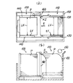
【図12】従来の給紙装置の第2用紙収容部の用紙束崩れ状態を示し、(a)は平面図、(b)は側断面図を示す。
【図13】従来の給紙装置の第1用紙収容部の用紙束崩れ状態を示し、(a)は平面図、(b)は側断面図を示す。
【符号の説明】
1 複写機
2 給紙装置
5 筐体
21a ピックアップローラ
23 第1用紙収容部
24 第2用紙収容部
27 第1載置台
28 第2載置台
48 用紙移送手段
60 孔版印刷装置
f1,f1’ 第1積載面
f2,f2’ 第2積載面
r 通紙経路
α 勾配
A1、A2 上向き凸部
P 用紙[0001]
BACKGROUND OF THE INVENTION
The present invention relates to a sheet feeding device in which a pair of sheet storage units are provided side by side, and in particular, a sheet feeding mechanism of a first sheet storage unit and a mechanism for transferring sheets of a second sheet storage unit to the first sheet storage unit. And an image forming apparatus having the same.
[0002]
[Prior art]
Copiers, printers, fax machines, printing devices, and the like are known as image forming apparatuses that pass a sheet through a sheet passing path from a sheet feeding unit to a sheet discharging unit and form a desired image on the sheet through the sheet passing path. It is used properly according to the application. The paper feed unit used in these image forming apparatuses stacks paper on its mounting table, separates the paper one by one by a paper feed roller, etc., and feeds it to the paper feed path. A desired image is formed, and the paper is sent to a paper discharge unit at the downstream end of the paper path.
[0003]
Such image forming apparatuses tend to be multi-functional, and accordingly, the sizes of sheets on which images can be formed are diversified and the number of sheets is increasing. For this reason, a plurality of types of paper feed trays are dispersedly arranged in the paper feed unit, and these selectively feed paper to feed the image forming process unit in the paper passing path.
In such a paper feed unit, paper feed trays having different sizes according to the paper size are distributed, and in particular, a paper with a large amount of consumption can accommodate a large number of paper bundles on a mounting table having a lifting function. A paper tray is used. In this case, if the paper is of a relatively small size, an air space tends to be generated on the rear side compared to other relatively large paper feed trays. In order to make effective use of this air space, there is known a paper feeding base side system in which a pair of paper storage portions are provided side by side. One example is disclosed in Japanese Patent Laid-Open No. 2000-108480.
[0004]
For example, as shown in FIGS. 12 and 13, a paper feeding apparatus that employs a paper feeding table with a plurality of paper storage units is provided with first and second
[0005]
[Problems to be solved by the invention]
By the way, in general, each paper feed table of the paper feed unit is provided with a pair of
[0006]
Therefore, when the
[0007]
Japanese Patent Application Laid-Open No. 2000-108480 discloses a paper feeding device that employs a paper feeding table with a plurality of paper storage units. However, the upper end of a sheet bundle between a pair of side fences on each paper feeding table is disclosed. It does not give any means to prevent the collapse.
In the present invention, based on the above problems, first, the edge of the paper placed on the stacking surface is curled to utilize the stiffness of the paper, and the first and second paper storage portions are attached to the paper feeding device. An object of the present invention is to provide a paper feeding device capable of suppressing the collapse of the sheet bundle toward the opposite end when the sheet is set in the section.
Second, there is provided a paper feeding device that can prevent the sheet bundle from collapsing toward the opposite end when the first and second paper storage portions are set on the paper feeding device mounting portion without curling the paper. The purpose is to provide.
[0008]
Thirdly, an object of the present invention is to provide a paper feeding device in which a first paper storage unit, a second paper storage unit, and a paper transfer unit are provided in a paper supply tray, and these can be easily set in a paper supply device mounting unit. .
A fourth object of the present invention is to provide a paper feeding device that can easily determine the necessity of replenishing paper in the second paper storage unit by means of the load amount detection means.
[0009]
A fifth object of the present invention is to provide a paper feeding device that can prevent malfunction of the paper feeding device by an erroneous set detection means.
Sixth, to provide an image forming apparatus capable of preventing the sheet feeding control from malfunctioning by performing the image forming control using the sheet feeding apparatus according to any one of
[0010]
Seventhly, an object of the present invention is to provide an image forming apparatus capable of obtaining the same effect as in the case of forming an image with an electrophotographic process or forming an image with a stencil printing apparatus. .
[0011]
[Means for Solving the Problems]
In order to achieve the above-mentioned object, the invention of
In this way, the paper end on the upward convex portion of the paper placed on at least one of the stacking surfaces is curled by the upward convex portion formed on at least one of the opposing end portions of the first and second stacking surfaces. . For this reason, curling of the edge of the sheet makes it possible to suppress the collapse of the sheet bundle toward the opposite end when the first and second sheet storage portions are set on the sheet feeding device mounting portion using the stiffness of the sheet.In addition, since the paper size and paper misalignment on the second stacking surface are detected by the erroneous set detection means, malfunction of the paper feeding device can be prevented.
[0012]
According to a second aspect of the present invention, there is provided a first sheet storage portion in which a plurality of sheets are stacked on the first stacking surface, and a second stacking surface that can be arranged in parallel so as to form a continuous surface with respect to the first stacking surface. 2. A sheet feeding apparatus comprising: a sheet storage unit; and a sheet transfer unit that collectively transfers a plurality of sheets on the second stacking surface onto the first stacking surface. At least one of the surfaces is provided with a gradient that rises toward the opposite edge of each otherThe second sheet storage unit is provided with an erroneous set detection means for detecting whether or not the sheets stacked on the second stacking surface are normally stacked.And features.
As described above, since at least one of the first stacking surface and the second stacking surface is provided with a gradient that rises toward the opposite edge of each other, the self-weight of the paper placed on at least one of the stacking surfaces is shifted in the regulation direction. Can work. For this reason, it is possible to suppress the collapse of the sheet bundle toward the opposite end when the first and second sheet storage portions are set on the sheet feeding device mounting portion without causing curling or the like on the sheets.In addition, since the paper size and paper misalignment on the second stacking surface are detected by the erroneous set detection means, malfunction of the paper feeding device can be prevented.
[0013]
According to a third aspect of the present invention, in the paper feeding device according to the first or second aspect, the first paper storage unit, the second paper storage unit, and a paper transfer unit are provided in a paper supply tray. .
As described above, since the first paper storage unit, the second paper storage unit, and the paper transfer unit are provided in the paper feed tray, the workability of setting the paper feed tray in the paper feed device mounting portion is improved.
[0014]
According to a fourth aspect of the present invention, in the paper feeding device according to the first, second, or third aspect, the stacking amount for detecting the amount of sheets stacked on the second stacking surface in the second sheet storage portion in a plurality of stages. A detection means is provided.
As described above, since the amount of paper on the second stacking surface is detected in a plurality of stages by the load amount detecting means, it is possible to easily determine the necessity of paper replenishment.
[0016]
Claim5According to another aspect of the present invention, there is provided an image forming apparatus that allows a sheet to pass through a sheet passing path from a sheet feeding unit to a sheet discharging unit, and forms a desired image on the sheet in the sheet passing path.4The sheet feeding device according to
Thus, the image forming apparatus comprises:4Since the sheet feeding device according to any one of the above descriptions is provided as the sheet feeding unit, it is possible to suppress the collapse of the sheet bundle in the first and second sheet storage units. It is possible to prevent a malfunction such as a set detection and the like from returning to the paper feed standby state.
[0017]
Claim6The invention of claim5In the described image forming apparatus, the image forming apparatus visualizes the latent image of the image carrier in the electrophotographic system to form a toner image, and transfers the toner image to the paper in the sheet passing path to form an image. It is characterized by doing.
Thus, when the image forming apparatus forms an image by an electrophotographic process, the same operation and effect as in the sixth aspect can be obtained.
[0018]
Claim7The invention of claim5In the image forming apparatus described above, the image forming apparatus is a stencil printing apparatus that winds a master on an outer peripheral surface of a plate cylinder and performs printing on a sheet of the sheet passing path.
Thus, even when the image forming apparatus is a stencil printing apparatus,5The same action and effect can be obtained.
[0019]
DETAILED DESCRIPTION OF THE INVENTION
1 and 2 show an electrophotographic copying machine (hereinafter simply referred to as a copying machine) 1 as an image forming apparatus using a sheet feeding device according to a first embodiment of the present invention. The copying
The
[0020]
The image forming
A main part of the
[0021]
The
[0022]
A
The
The first and second
[0023]
The first loading table 27 of the first
[0024]
As shown in FIGS. 1 and 4, a push-up
[0025]
In the vicinity of the
[0026]
A
[0027]
As shown in FIG. 5, the driven roller 32b is supported by a guide member (not shown) provided in the
[0028]
As shown in FIGS. 1 and 3, the first mounting table 27 detects a presence or absence of a pair of
[0029]
Next, the second
[0030]
The erroneous set detection means 57 is mounted on the side wall portion of the second mounting table 28 via a
[0031]
The
[0032]
Here, the first and second placement tables 27 and 28 of the first and second
[0033]
In the vicinity of the pickup roller 21b facing the second
[0034]
In addition, the second
[0035]
When the image forming operation is started in the image forming
[0036]
Prior to this, the control means (not shown) has a first paper feed tray.17The first and second paper presence /
[0037]
Here, when all the sheets P are stacked at the proper positions, the control unit is held in a sheet feeding standby state, and starts to drive the above-described image forming
When a paper size abnormality or a wrong set is detected, it is not possible to return to the paper feed standby state, and a wrong set is displayed on an operation panel (not shown). In response to this, the operator replaces the sheets P and PL on the first and second
Further, when it is detected that there is no paper P on the first loading table 23 of the first
[0038]
As shown in FIGS. 8A-1 and 8A-2, the first
[0039]
When the consumption of the paper P progresses and the paper P on the first loading table 23 of the first
[0040]
During the transfer of the bundle of sheets P, as shown in FIG. 6A, the second placement surface f2 of the second placement table 28 and the upward convex portion A1 of the first placement surface f1 facing the second placement surface f1 are approximately. At the same height, on the continuous surface, the paper P is smoothly transferred. In addition, the sheet P after passing through the upward convex portion A1 is curled by pushing up only the end portion facing the upward convex portion A1.
[0041]
For this reason, the edge of the paper P is curled so that the stiffness of the paper P can be used. After the stack of paper is properly stacked, the upper end side of the paper P collapses and displaces in the opposite end direction s1 due to impact or vibration. Can be suppressed. In particular, the impact caused by the speed when the first
[0042]
As described above, the upward convex portion A1 is formed at the end of the first placement surface f1 facing the second placement surface f2, but instead of this, as shown in FIG. An upward convex portion A2 may be formed in the paper width direction (perpendicular to the paper surface) at the end of the second placement table 28 opposite to the first placement surface f1 of the second placement surface f2. One
[0043]
In the above description, the first and second mounting surfaces f1 and f2 are formed with the upward convex portions A1 and A2 at either one of the opposing end portions. On the second placement surfaces f1 and f2, upward convex portions A1 and A2 may be formed at opposite ends of each other. In this case, both sheet bundles of the first and second
[0044]
Furthermore, upward convex portions A1 and A2 are formed on at least one of the first and second placement surfaces f1 and f2 of the first and second
[0045]
FIG. 11 shows a
In the
[0046]
The
[0047]
The
[0048]
The
[0049]
The registration unit 71 is composed of a pair of rollers facing each other across the conveyance path of the paper P. The
[0050]
During the operation of the
[0051]
In the
In the above description, the image forming apparatus is described as the copying
[0052]
【The invention's effect】
As described above, the invention according to
In the second aspect of the invention, since at least one of the first stacking surface and the second stacking surface is provided with a gradient that rises toward the opposite edge of each other, the weight of the paper placed on at least one of the stacking surfaces is reduced. It can work in the direction of deviation regulation. For this reason, it is possible to suppress the collapse of the sheet bundle toward the opposite end when the first and second sheet storage portions are set on the sheet feeding device mounting portion without causing curling or the like on the sheets.In addition, since the paper size and paper misalignment on the second stacking surface are detected by the erroneous set detection means, malfunction of the paper feeding device can be prevented.
[0053]
According to the third aspect of the present invention, since the first paper storage portion, the second paper storage portion, and the paper transfer means are provided in the paper feed tray, the workability of setting the paper feed tray to the paper feed device mounting portion is improved.
According to the fourth aspect of the present invention, since the amount of paper on the second stacking surface is detected in a plurality of stages by the load amount detecting means, it is possible to easily determine the necessity of paper supply.
[0055]
Claim5In the present invention, the image forming apparatus is the first aspect.4Since the sheet feeding device according to any one of the above descriptions is provided as the sheet feeding unit, it is possible to suppress the collapse of the sheet bundle in the first and second sheet storage units. It is possible to prevent a malfunction such as a set detection and the like from returning to the paper feed standby state.
[0056]
Claim6The invention of
Claim7According to the present invention, even when the image forming apparatus is a stencil printing apparatus,5The same action and effect can be obtained.
[Brief description of the drawings]
FIG. 1 is a schematic configuration diagram of a main part of a sheet feeding device as an embodiment of the present invention and a copier as an image forming apparatus to which the sheet feeding device is attached.
2 is an exploded perspective view showing an appearance of the copying machine of FIG. 1. FIG.
FIG. 3 is a schematic perspective view of a main part of a paper feeding device attached to the copier of FIG.
4 is an enlarged configuration diagram of an elevating mechanism unit used by the paper feeding device in FIG. 1. FIG.
5 is an enlarged configuration diagram of a support mechanism portion of a pickup roller used by the paper feeding device in FIG. 1. FIG.
6 is an enlarged cutaway view of a main part of first and second mounting tables used by the paper feeding device in FIG. 1. FIG.
7 is an enlarged cutaway view of a main part of first and second mounting tables as another embodiment used by the paper feeding device in FIG. 1. FIG.
8 is an enlarged plan view of the first and second mounting tables used by the paper feeding device in FIG. 1, in which (a-1) and (a-2) are stationary, and (b-1) and (b -2) indicates when the paper is out.
9 is an enlarged plan view of the first and second mounting tables used by the paper feeding device in FIG. 1, wherein (a-1) and (a-2) indicate the time of paper transfer, and (b-1) and (b) b-2) shows the time when the paper transfer is completed.
FIG. 10 is a schematic configuration diagram of a main part of a stencil printing machine as an image forming apparatus to which a paper feeding device according to another embodiment of the present invention is attached.
11 is a perspective view showing an external appearance of the stencil printing machine shown in FIG.
FIGS. 12A and 12B show a sheet bundle collapse state of a second sheet storage portion of a conventional sheet feeding device, where FIG. 12A is a plan view and FIG. 12B is a side sectional view.
FIGS. 13A and 13B show a sheet bundle collapse state of a first sheet storage unit of a conventional sheet feeding device, where FIG. 13A is a plan view and FIG. 13B is a side sectional view.
[Explanation of symbols]
1 Copying machine
2 Paper feeder
5 Case
21a Pickup roller
23 First paper storage section
24 Second paper storage unit
27 First mounting table
28 Second mounting table
48 Paper transport means
60 Stencil printing machine
f1, f1 'first loading surface
f2, f2 'second loading surface
r Paper path
α gradient
A1, A2 Upward convex part
P paper
Claims (7)
前記第1積載面と第2積載面の互いの対向端部のうち少なくとも一方に上向き凸部を形成し、
前記第2用紙収容部には前記第2積載面に積載される用紙が正常積載か否かを検出する誤セット検知手段が設けられていることを特徴とする給紙装置。A second paper storage unit having a first paper storage unit in which a plurality of sheets are stacked on the first stacking surface and a second stacking surface that can be arranged in parallel so as to be substantially parallel to the first stacking surface. A sheet feeding device comprising: a section; and a sheet transporting unit that collectively transports a plurality of sheets of the second stacking surface onto the first stacking surface;
Forming an upward convex portion on at least one of the opposing ends of the first loading surface and the second loading surface ;
Wherein the second sheet storage portion the sheet feeding apparatus which is characterized that you erroneous setting detection means paper to be stacked on the second stacking surface to detect whether normal loading or provided.
前記第1積載面と第2積載面のうち少なくとも一方に互いの対向端縁に近づくほど上昇する勾配を設け、
前記第2用紙収容部には前記第2積載面に積載される用紙が正常積載か否かを検出する誤セット検知手段が設けられていることを特徴とする給紙装置。A first sheet storage unit configured to stack a plurality of sheets on a first stacking surface; a second sheet storage unit having a second stacking surface that can be arranged in parallel so as to form a continuous surface with respect to the first stacking surface; A sheet feeding device comprising a sheet transporting unit configured to collectively transport a plurality of sheets on the second stacking surface onto the first stacking surface;
The ramp rising closer to opposing end edges of each other in at least one of the first stacking surface and the second stacking surface provided,
Wherein the second sheet storage portion the sheet feeding apparatus which is characterized that you erroneous setting detection means paper to be stacked on the second stacking surface to detect whether normal loading or provided.
請求項1乃至4記載のいずれか一つに記載の給紙装置を前記給紙部として備えたことを特徴とする画像形成装置。 In an image forming apparatus for passing a sheet through a sheet passing path from a sheet feeding unit to a sheet discharging unit and forming a desired image on the sheet of the sheet passing path.
An image forming apparatus comprising the sheet feeding device according to claim 1 as the sheet feeding unit.
Priority Applications (1)
| Application Number | Priority Date | Filing Date | Title |
|---|---|---|---|
| JP2000357887A JP3933865B2 (en) | 2000-11-24 | 2000-11-24 | Paper feeding device and image forming apparatus |
Applications Claiming Priority (1)
| Application Number | Priority Date | Filing Date | Title |
|---|---|---|---|
| JP2000357887A JP3933865B2 (en) | 2000-11-24 | 2000-11-24 | Paper feeding device and image forming apparatus |
Publications (2)
| Publication Number | Publication Date |
|---|---|
| JP2002160836A JP2002160836A (en) | 2002-06-04 |
| JP3933865B2 true JP3933865B2 (en) | 2007-06-20 |
Family
ID=18829881
Family Applications (1)
| Application Number | Title | Priority Date | Filing Date |
|---|---|---|---|
| JP2000357887A Expired - Fee Related JP3933865B2 (en) | 2000-11-24 | 2000-11-24 | Paper feeding device and image forming apparatus |
Country Status (1)
| Country | Link |
|---|---|
| JP (1) | JP3933865B2 (en) |
Families Citing this family (3)
| Publication number | Priority date | Publication date | Assignee | Title |
|---|---|---|---|---|
| JP5194300B2 (en) * | 2008-07-10 | 2013-05-08 | 東北リコー株式会社 | Image forming apparatus |
| JP6600200B2 (en) * | 2015-09-08 | 2019-10-30 | キヤノン株式会社 | Image forming apparatus |
| KR20240100030A (en) * | 2022-12-22 | 2024-07-01 | 주식회사 엘지에너지솔루션 | Battery pack elevating device |
-
2000
- 2000-11-24 JP JP2000357887A patent/JP3933865B2/en not_active Expired - Fee Related
Also Published As
| Publication number | Publication date |
|---|---|
| JP2002160836A (en) | 2002-06-04 |
Similar Documents
| Publication | Publication Date | Title |
|---|---|---|
| JP5378438B2 (en) | Image forming apparatus | |
| US7822359B2 (en) | Image forming apparatus having a control device which is rotatably linked | |
| US9170548B2 (en) | Sheet discharge device, and image forming apparatus provided with the same | |
| JPH07179250A (en) | Automatic printing device | |
| JP2010111511A (en) | Paper loading device and image forming device | |
| JP3933865B2 (en) | Paper feeding device and image forming apparatus | |
| JP4057232B2 (en) | Paper detection sensor and image forming apparatus | |
| JP3310424B2 (en) | Image forming apparatus and optional paper feeder | |
| JPH04182234A (en) | Paper supply device of recording device | |
| JP2003128339A (en) | Paper discharge device of image forming device | |
| JP2000318845A (en) | Cassette tray, and image forming device | |
| JP3133406B2 (en) | Paper feeder | |
| JP3611539B2 (en) | Image forming apparatus | |
| JP3589973B2 (en) | Discharge tray and image forming apparatus having the same | |
| JP2738871B2 (en) | Paper feeder in copier | |
| JP3927198B2 (en) | Paper feeder | |
| JP2815224B2 (en) | Image forming apparatus feeding method | |
| JP2006240801A (en) | Image forming apparatus | |
| JP3806066B2 (en) | Image forming apparatus | |
| JP4076956B2 (en) | Paper feeder | |
| JPH1111691A (en) | Paper feeding device | |
| JPH0577965A (en) | Image forming device | |
| JPH0286571A (en) | Sheet refeeder | |
| JP2825625B2 (en) | Multi-stage paper feeder | |
| JPH08245043A (en) | Built-in paper discharge device of image forming device |
Legal Events
| Date | Code | Title | Description |
|---|---|---|---|
| A621 | Written request for application examination |
Free format text: JAPANESE INTERMEDIATE CODE: A621 Effective date: 20050126 |
|
| A977 | Report on retrieval |
Free format text: JAPANESE INTERMEDIATE CODE: A971007 Effective date: 20060630 |
|
| A131 | Notification of reasons for refusal |
Free format text: JAPANESE INTERMEDIATE CODE: A131 Effective date: 20060822 |
|
| A521 | Written amendment |
Free format text: JAPANESE INTERMEDIATE CODE: A523 Effective date: 20061023 |
|
| TRDD | Decision of grant or rejection written | ||
| A01 | Written decision to grant a patent or to grant a registration (utility model) |
Free format text: JAPANESE INTERMEDIATE CODE: A01 Effective date: 20070306 |
|
| A61 | First payment of annual fees (during grant procedure) |
Free format text: JAPANESE INTERMEDIATE CODE: A61 Effective date: 20070314 |
|
| R150 | Certificate of patent or registration of utility model |
Free format text: JAPANESE INTERMEDIATE CODE: R150 |
|
| FPAY | Renewal fee payment (event date is renewal date of database) |
Free format text: PAYMENT UNTIL: 20100330 Year of fee payment: 3 |
|
| FPAY | Renewal fee payment (event date is renewal date of database) |
Free format text: PAYMENT UNTIL: 20100330 Year of fee payment: 3 |
|
| FPAY | Renewal fee payment (event date is renewal date of database) |
Free format text: PAYMENT UNTIL: 20100330 Year of fee payment: 3 |
|
| FPAY | Renewal fee payment (event date is renewal date of database) |
Free format text: PAYMENT UNTIL: 20110330 Year of fee payment: 4 |
|
| FPAY | Renewal fee payment (event date is renewal date of database) |
Free format text: PAYMENT UNTIL: 20120330 Year of fee payment: 5 |
|
| FPAY | Renewal fee payment (event date is renewal date of database) |
Free format text: PAYMENT UNTIL: 20130330 Year of fee payment: 6 |
|
| FPAY | Renewal fee payment (event date is renewal date of database) |
Free format text: PAYMENT UNTIL: 20140330 Year of fee payment: 7 |
|
| LAPS | Cancellation because of no payment of annual fees |