JP3927570B2 - container - Google Patents
container Download PDFInfo
- Publication number
- JP3927570B2 JP3927570B2 JP2004280215A JP2004280215A JP3927570B2 JP 3927570 B2 JP3927570 B2 JP 3927570B2 JP 2004280215 A JP2004280215 A JP 2004280215A JP 2004280215 A JP2004280215 A JP 2004280215A JP 3927570 B2 JP3927570 B2 JP 3927570B2
- Authority
- JP
- Japan
- Prior art keywords
- container
- measurement
- light
- microplate
- base
- Prior art date
- Legal status (The legal status is an assumption and is not a legal conclusion. Google has not performed a legal analysis and makes no representation as to the accuracy of the status listed.)
- Expired - Fee Related
Links
Images


Landscapes
- Apparatus Associated With Microorganisms And Enzymes (AREA)
- Automatic Analysis And Handling Materials Therefor (AREA)
Description
容器 技術分野 この発明は、厳密な定量精度が要求される分析検査に好適な容器に係り、特に、容器の内底面にピペットチップの先端部が当接しても該容器内の試料をほぼ全量吸引することができると共に、容器内に吸引した試料を吐出するときの試料の拡散を平均化して撹拌効率を大幅に向上させることができる容器に関する。 TECHNICAL FIELD The present invention relates to a container suitable for analysis and inspection that requires strict quantitative accuracy. In particular, even when the tip of the pipette tip comes into contact with the inner bottom surface of the container, almost all of the sample in the container is aspirated. The present invention relates to a container that can improve the stirring efficiency by averaging the diffusion of the sample when the sample sucked into the container is discharged.
周知のように、分析精度をハイレベルで保持するためには、分注装置による定量精度を厳密に維持する必要があるが、従来の容器の場合、内底部が平面的に形成され、或は、断面形状が半円形または略U字状に形成されているため、分注装置のピペットチップ先端部を容器の内底部に当接させた状態では試料・試薬の吸引・吐出ができず、その結果、上記ピペットチップの先端部は必ず容器の内底部から若干浮かせた状態で試料・試薬の吸引を行なわなければならないため、容器側には常に僅かな試料・試薬が残留することとなり、これを補うためには、実際の吸引量より多めの試料・試薬をピペットチップで吸引・吐出しなければならず、容器内に吸引されない試料・試薬が残ってしまうことはやむを得ず、その結果、厳密な定量分析を行なうことができない、という問題を有していた。
このような問題を解決するための従来の手段としては、例えば、第16図に示すように、ピペットチップ1の先端部2を斜めにカットし、該ピペットチップ1の先端部2を容器3の内底部4に当接させた状態のまま試料Sの吸引・吐出ができるように構成したものや、第18図に示すように、ピペットチップ1の下端部に1個以上の横穴5を開設したものも提案されており、ピペットチップ1の先端開口部が容器3の内底部4によって閉塞されないような工夫が施されている。
しかしながら、ピペットチップ1の先端部2を斜めにカットした場合であっても、斜めにカットされた先端開口部の上端部よりやや下方の水位Wから下の部分を完全に吸引することができず、また、吸引された試料・試薬を容器3内に吐出した場合には、第17図に示すように、容器3の一方側が吐出圧力によって撹拌されるが、上記斜めにカットされた先端部の開口側と反対側は、試料・試薬の吐出圧力の影響を直接受けないため、撹拌効率が低く、このため、均一な撹拌効果、即ち、均一な反応状態を得にくく、さらには、ピペットチップの成形も難しくなりコスト高となる、という問題を有していた。
同様に、ピペットチップ1の下端部に横穴5を開設したものも、該横穴5の開設部位から下方部分の液体Sを吸引することができず、また、吸引した液体を吐出するときも、上記横穴5の開設方向からしか液体が吐出されないので、均一な撹拌効果が得にくく、しかも、1個以上の横穴5を開設する、という工程が加わるので、成形が複雑化してコスト高となる、という問題を有していた。
また、ピペットチップの先端部を容器の内底部から浮かせた状態で液体を吸引し吐出する場合、該ピペットチップの外表面に試料・試薬が滴着し易く、この滴着した試料・試薬によって試料濃度が変動するため、高精度な分析結果が得にくい、という問題も有していた。
As is well known, in order to maintain the analysis accuracy at a high level, it is necessary to strictly maintain the quantitative accuracy by the dispensing device. In the case of a conventional container, the inner bottom is formed in a plane, or Because the cross-sectional shape is semicircular or substantially U-shaped, the sample / reagent cannot be aspirated / discharged when the tip of the pipette tip of the dispensing device is in contact with the inner bottom of the container. As a result, since the sample / reagent must always be aspirated while the tip of the pipette tip is slightly lifted from the inner bottom of the container, a small amount of sample / reagent always remains on the container side. In order to compensate, it is necessary to aspirate and discharge a larger amount of sample / reagent with the pipette tip than the actual aspiration amount, and it is unavoidable that the sample / reagent not aspirated remains in the container. Analysis Ukoto can not, had the problem.
As a conventional means for solving such a problem, for example, as shown in FIG. 16, the
However, even when the
Similarly, the one having the
In addition, when a liquid is sucked and discharged with the tip of the pipette tip floating from the inner bottom of the container, the sample / reagent is easily deposited on the outer surface of the pipette tip. Since the concentration fluctuated, there was a problem that it was difficult to obtain a highly accurate analysis result.
この発明は、かかる現状に鑑み創案されたものであって、その目的とするところは、第一には、一連の処理に必要とする種々の容量をもつ処理用、測定用、又は分注チップ保持用等の収容部を1つの容器内に備えることによって、迅速で効率の良い処理を行うことである。第二には、処理の開始から終了までの間の操作処理に必要な機械的な駆動を削減して、可動部の少ない処理を行うことである。 The present invention has been developed in view of the present situation. The purpose of the present invention is, firstly, for processing, measuring, or dispensing tips having various capacities required for a series of processing. By providing a container for holding or the like in one container, a quick and efficient process is performed. Secondly, the mechanical drive required for the operation process from the start to the end of the process is reduced, and the process with few movable parts is performed.
上記目的を達成するため、第一の発明に係る容器は、カートリッジ容器またはマイクロプレートが、基部と、当該基部に列状またはマトリクス状に各々設けられた複数個の収容部とを有し、当該複数個の収容部には、処理用の収容部、および、光学測定用の測定器若しくは受光部と遮光状態で連結可能な測定用収容部が処理に応じた必要数含まれているとともに、前記測定用収容部の上端は、前記光学測定用の測定器又は受光部と遮光状態で連結する環状の凸部からなる連結部が設けられたものである。
これによって、光学的測定までの処理を1つの容器で行うことができるので、機械的な駆動を最小限に抑え、液体等の移動の距離及び時間を短縮し、処理を迅速に信頼性良く、処理を一括して行うことができる。
第二の発明に係る容器は、第一の発明において、前記カートリッジ容器又はマイクロプレートの基部が透明物質又は半透明物質等の透光性物質で形成され、前記測定用収容部は、遮光された測定用容器を着脱自在に保持するための容器保持用穴部及び当該容器保持用穴部に保持された測定用容器からなるものである。
透明物質等の透光性物質で形成されたマイクロプレートの製造とは別個に遮光された測定用容器を製造することができるので、製造が容易であり、安価に製造することができる。
第三の発明に係る容器は、第一の発明において、前記カートリッジ容器又はマイクロプレートの基部が遮光性物質で形成され、前記測定用収容部は、基部と一体に形成されているものである。
第四の発明に係る容器は、第一の発明又は第二の発明のいずれかにおいて、前記測定用収容部に保持される測定用容器が、その測定用容器の内壁は白色の彩色等によって高反射率となるように形成され、その外側は遮光物質で覆われているものである。
「高反射率となる」ためには、白色の彩色の他に、白色物質で形成する場合、金属色の彩色や、金属で形成する場合等がある。
これによって、外部からの遮光とともに、発光によって生じた光を確実に受光部又は測定器に入射させて、信頼性のある測定を行うことができる。
第五の発明に係る容器は、第一の発明乃至第四の発明のいずれかにおいて、前記マイクロプレート又はカートリッジ容器が、略平板状の基部と、当該基部にマトリクス状又は直列状に設けられた複数個の収容部と、当該基部の周縁から下方に向けて前記収容部の外底部よりも突出して基部を支える脚壁部とを有するものである。
第六の発明に係る容器は、第一の発明乃至第五の発明のいずれかにおいて、前記カートリッジ容器又は前記マイクロプレートの基部の上表面が、各収容部の開口を覆うため、ピペットチップが進入可能なシールが熱溶着又は超音波溶着によって設けられているものである。
ここで、「ピペットチップが進入可能なシール」には、シール自体が強度が小さい薄膜で容易に貫通しやすいものである他、シール自体の強度は大きいがシール自体に穴が形成されていてピペットチップが進入可能なものであっても良い。
シールは透明のみならず半透明又は不透明であっても良く、アルミニウム箔やポリ塩化ビニール等で形成される。
処理は、分注チップをシールを貫通して収容部に差し込むことによって行う。
これによって、各収容部内に予め収容されている液体の蒸発やコンタミを防止するとともに、外部からの雑菌の侵入を防止することができるので、信頼性の高い処理を効率良く行うことができる。
In order to achieve the above object, a container according to a first aspect of the present invention includes a cartridge container or a microplate having a base portion and a plurality of storage portions respectively provided in a row or matrix form on the base portion. The plurality of storage units include a processing storage unit and a necessary number of measurement storage units that can be connected to a measuring instrument or a light receiving unit for optical measurement in a light-shielded state according to the processing. The upper end of the measurement housing portion is provided with a connecting portion composed of an annular convex portion that is connected to the optical measuring instrument or light receiving portion in a light-shielded state.
As a result, the process up to the optical measurement can be performed in one container, so that the mechanical driving is minimized, the distance and time of movement of the liquid etc. are shortened, and the process is quickly and reliably performed. Processing can be performed collectively.
A container according to a second invention is the container according to the first invention, wherein the base of the cartridge container or the microplate is formed of a translucent material such as a transparent material or a translucent material, and the measurement container is shielded from light It consists of a container holding hole for detachably holding the measurement container and a measurement container held in the container holding hole.
Since the measurement container that is shielded from light can be manufactured separately from the manufacturing of the microplate formed of a transparent material such as a transparent material, the manufacturing is easy and the manufacturing can be performed at low cost.
A container according to a third invention is the container according to the first invention, wherein a base part of the cartridge container or the microplate is formed of a light-shielding substance, and the measurement housing part is formed integrally with the base part.
A container according to a fourth invention is the container according to any one of the first invention and the second invention, wherein the measurement container held in the measurement container has a high inner wall of the measurement container due to white coloring or the like. It is formed so as to have a reflectance, and its outer side is covered with a light shielding material.
In order to “high reflectivity”, in addition to the white coloring, there are cases where the white material is used, a metallic color, and a metal.
This makes it possible to perform reliable measurement by blocking light from the outside and also making sure that light generated by light emission is incident on the light receiving unit or the measuring device.
A container according to a fifth invention is the container according to any one of the first invention to the fourth invention, wherein the microplate or cartridge container is provided in a substantially flat plate-like base and a matrix or series in the base. It has a plurality of accommodating portions and leg wall portions that protrude downward from the outer bottom portion of the accommodating portion toward the lower side from the periphery of the base portion and support the base portion.
A container according to a sixth invention is the container according to any one of the first to fifth inventions, wherein the upper surface of the base of the cartridge container or the microplate covers the opening of each accommodating part, so that the pipette tip enters. Possible seals are those provided by thermal welding or ultrasonic welding.
Here, the “seal into which the pipette tip can enter” is a thin film having a low strength and easily penetrates, and the seal itself has a high strength but a hole is formed in the seal itself. The chip may be one that can enter.
The seal may be not only transparent but also translucent or opaque, and is formed of aluminum foil or polyvinyl chloride.
Processing is performed by inserting the dispensing tip through the seal and into the receiving part.
As a result, evaporation and contamination of the liquid previously stored in each storage unit can be prevented, and intrusion of germs from the outside can be prevented, so that highly reliable processing can be performed efficiently.
以下、添付図面に示す実施例に基づき、この発明を詳細に説明する。
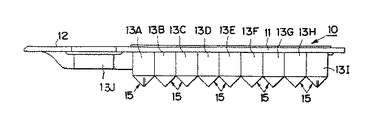
図1乃至図6は、この発明の第1実施例に係る容器を示しており、この実施例に係る容器10は、ガラスやプラスチック等で一体形成された容器本体11と、この容器本体11の一端に形成された摘み12とを有して構成されてなるカートリッジ容器で構成されており、上記容器本体11には、複数個(図示の例では9個)の液体収容部13A乃至13Iと、測定用容器14を着脱自在に保持する容器保持穴13Jと、が形成されている。
上記液体収容部13A乃至13I内は、この実施例では、収容物を外部から透視できるように透明なプラスチックまたはガラスで形成されているため、上記容器保持穴13Jに着脱自在に保持される透明体で形成された上記測定用容器14の内壁および底部は、微弱な化学発光を確実に測定できるように、遮光膜でコーティングされて形成されている。即ち、この実施例に係る容器10は、透明体である容器本体11と測定用容器14との2パーツで形成されている。
勿論、上記測定用容器14を、微弱な化学発光を確実に測定できるように構成する他の手段としては、その内壁および底部に遮光膜や遮光板を張る等の処理を施して一体にアッセンブリーして3パーツで構成し、或は、容器本体11自体を遮光性に優れた材質で不透明に形成し、或は、黒色や白色等の遮光性に優れた彩色を施して一体形成しても良い。
また、上記測定用容器14を透明体のままで用いる場合には、上記容器保持穴13Jを有底状に形成し、該容器保持穴13Jの内面に遮光膜をコーティングして一体成形し、または、遮光板を張る等して一体にアッセンブリーし、或は、黒色や白色等の遮光性に優れた彩色を施して形成するのが望ましい。
勿論、測定用容器14は、図7に示すように、測定用容器穴部14Aとして上記容器本体11に形成された液体収容部列と一体に形成してもよく、この場合には、該測定用容器穴部14Aの内壁および底部に、遮光膜をコーティングして一体成形し、または、遮光板を張る等して一体にアッセンブリーし、或は、黒色や白色等の遮光性に優れた彩色を施して遮光層14Bを形成するのが望ましい。
このように測定用容器14または測定用容器穴部14Aを形成することで、例えば、化学発光の測定に該測定用容器14を用いたときに、反応によって生じた光以外の光を遮断することができる。勿論、透過測定法や分光測定法或は比濁法等のような測定法によっては遮光を施す必要がない場合があり、この場合には、透明なままで使用する。
尚、上記測定用容器14または測定用容器穴部14Aの配置部位は、図示の実施例に限定されるものではなく、測定項目の反応工程数等に対応させて適宜の位置に形成できることは勿論である。
上記9個の液体収容部13A乃至13Iは、平面形状が略楕円形に形成されていると共に、各底部15が断面略V字状(図示の例では交差角度が90°)に形成され、かつ、図1に示すように、上記各底部15の内底部15aには、断面略凹状の一条の溝16が各内底部15aの傾斜面に沿って形成されている。
この溝16は、その幅寸法dが、図8と第9図に示すように、ピペットチップ21の先端部22の口径寸法Dよりも小さく形成されている(D>d)と共に、該溝16の長さは、上記先端部22の口径寸法よりも長く形成されているので、ピペットチップ21の先端部22が上記各内底部15aに当接しても、図8に示すように、各液体収容部13A乃至13I内に収容された試料・試薬が、該溝16を流れて全量吸引することができ、この種の装置における厳密な定量性を確実に保証することができ、また、試料・試薬の無駄も排除することができる。
尚、この実施例では、CLIA検査法やCLEIA検査法等の化学発光法の分析検査で用いられる磁性体微粒子17が含有されている試料・試薬18が図示されているが、この発明に用いられる試料・試薬はこれに限定されるものではなく、例えば、抗原−抗体を上記液体収容部13の内壁面に固相してEIA検査にも用いることもできる。勿論、例示した検査法に限定されるものではなく、他の検査にも適用することもできる。
さらに、上記溝16の存在により、試料・試薬を各液体収容部13A乃至13I内に吐出するときに、上記ピペットチップ21の先端部22を各液体収容部13A乃至13Iの内底部15aに当接させたとしても、図9に示すように、吐出される試料・試薬は上記溝16から各液体収容部13A乃至13I内へと左右方向にほぼ平均して流出するので、試料・試薬の吐出による撹拌流が液体収容部13A乃至13I内で平均化されるので、均一な反応状態を得ることができる。
尚、上記液体収容部13A乃至13Iの数は、図示の実施例に限定されるものではなく、測定項目の反応工程数等に対応させて適宜の数に形成できることは勿論である。
図10は、この発明の第2実施例に係る容器10の液体収容部13の平面図であり、この実施例では、前記第1実施例の溝16と同様に形成されてなる溝16Aを放射状に形成することで、液体収容部13内の試料・試薬の全量吸引・吐出をより迅速に、かつ、確実に行なうように構成されている他は、他の構成・作用は、前記第1実施例と同様であるので、その詳細な説明をここでは省略する。
図11は、この発明の第3実施例に係る容器10の液体収容部13の平面図であり、この実施例では、前記第1・第2実施例の溝16,16Aに代えて多数の突起または凹孔16Bを形成し、これら各突起または凹孔16B間の寸法をピペットチップ21の先端部22の口径寸法よりも小さく、かつ、ピペットチップ21の先端部22の開口寸法よりも若干大きく形成することで、試料・試薬の全量吸引・吐出を実現できるように構成した他は、他の構成・作用は、前記第1実施例と同様であるので、その詳細な説明をここでは省略する。
次に、本発明の第4の実施例として、各液体収容部をマトリクス状(行列状)に配列したマイクロプレート30について、図12及び第13図に基づいて説明する。
マイクロプレート30は、複数の並設された液体吸引・吐出ラインで処理する場合に、各ラインとも同じタイミングで目的高分子物質等の分離・分取・分注・清澄・濃縮・希釈等の作業または/および捕獲・抽出・単離・増幅・標識・測定等の作業を行う場合に用いる。
図12及び第13図に示すように、本実施例に係るマイクロプレート30は、透明又は半透明物質で形成された略板状の基部35と、当該基部35にマトリクス状に設けられた複数の収容部31A〜31K、32A〜32K、33A〜33K,34A〜34Kとを有する。複数個の収容部は、各行(列)毎に区分した4個の収容部群31A〜31K、32A〜32K、33A〜33K,34A〜34Kからなる。
各行(列)毎に区分した各収容部群の内、一端にある収容部31K,32K,33K,34Kは、光学測定用の測定器又は受光部(図示せず)と遮光状態で連結可能な測定用の収容部である。
当該測定用の収容部31K,32K,33K,34Kは、遮光された測定用容器331を着脱可能に保持する容器保持用穴部330と、遮光性のある測定用容器331から成っている。これは、基部35自体に遮光性がないのに対し、測定用の収容部は遮光性を必要とするため、測定用の収容部を含めて一度に成型するよりも製造が容易だからである。
測定用容器331は、外部が黒色の遮光性物質で形成され、内部は白色の遮光性且つ反射性の高い物質で形成されている。
測定用容器331の上端は、光学測定用の測定器又は受光部と遮光状態で連結する環状の凸部からなる連結部332が設けられ、測定器又は受光部に設けられた弾性体のパッキンを押圧することによって遮光を完全にしている。
測定用容器331は、これによって、遮光物質で形成された黒色の測定用容器331を予め基部35に一体で形成するよりも製造が容易で安価に形成することができる。
図12に示すように、好ましくは、当該マイクロプレート30の上表面は、各収容部を覆うため、分注チップの先端が容易に侵入可能な透明薄膜でできたシール300を熱溶着又は超音波溶着によって設ける。これによって、各収納部に予め収容されている液体の蒸発を防止するとともに、外部からの雑菌の侵入を防止することができるので、信頼性の高い処理を効率よく行うことができる。
図13に示すように、マイクロプレート30は、基部35の周縁から下方に向けて前記各収容部の外底部39よりも突出して基部35を支える脚壁部36が設けられている。また、隣接する各収容部間には、補強用のリブ38が設けられている。
これによって、マイクロプレートを分注装置のステージ上に安定して載置することができる。
図14は、本発明の第5の実施例を示す。
本実施例に係るマイクロプレート40は、8列の収容部群41A〜41H、…48A〜48Hが設けられている。
各収容部群の一端は、8連の分注ノズルに装着して用いるピペットチップ51を脱着した場合に保持するチップ保持用収容部41A〜48Aであり、他端は、前述した測定用の収容部41H〜48Hである。また、両端を除いた各収容部41B〜41G、…、48B〜48Gは、処理に応じて必要となる液体(試薬等)の必要量に対応する種々の容量をもつように形成されている。
図14(a)中、左端にあるのは、当該マイクロプレート40の各処理用の収容部に対して分注動作を行うための8連の分注ノズルに装着された8個の連動するピペットチップ51と、各ピペットチップ51に対し、一斉に近接又は離間することによって、ピペットチップ51の太径の貯溜部と先端とを結ぶ中径の液通路内に対し磁場を及ぼし又は磁場を除去することによって、同時に磁性体粒子53の反応、攪拌、分離、洗浄及び移送等の制御を行う8個の永久磁石52と、当該8個の永久磁石52を保持して移動する移動体50とが示されている。
8個の隣接する各永久磁石間では、そのSN極性を相互に反転させた状態で配列する。
これによって、隣接する磁石に対する磁場の干渉を防止して、安定した制御を行うことができる。
本実施例でも、図14に示すように各収容部の内底部には、断面略凹状の一条の溝が傾斜面に沿って形成されている点については図1等で説明したのと同様である。
続いて、図15に基づいて、第6の実施例について説明する。
当該実施例は、DNAの検査の処理に適した容器である。
図15(a)に示すように、本実施例に係るマイクロプレート60は、収容部が列(行)毎に設けられた複数のカートリッジ61,62,63,64と、隣接するカートリッジ間を所定間隔を空けて並べその一端で略クシ歯状に結合する結合部66とを有する。
当該結合部66には、マイクロプレート60を掴むためのツマミ67が設けられている。
本実施例では、各カートリッジ及び結合部等は金型によって、一体に成型される。
ここで、「所定間隔」としては、当該マイクロプレート60が載置されるステージに設けられた隔壁65が挿入可能なように、隔壁65の厚みよりもやや広めに設定される。隔壁65がカートリッジ間の間隙に挿入されると隣接するカートリッジが隔てられる。
同図(b)に示すように、本実施例では、各列毎のカートリッジ63等は、その一端は、分注ノズルから脱着された分注チップ69を保持する分注チップ保持用収容部63Aが設けられ、他端には、DNAの測定を行うために用いるPCR用チューブ635を保持する保持用穴部63Iが設けられている。
PCR用チューブ635は、その上端に、液体の蒸発を防ぐための開閉自在の蓋体633がPCR用チューブ本体と一体に成型され、PCR用チューブ635に設けられたフランジ634によって前記保持用穴部63Iに支持されている。
さらに、本実施例にあっては、処理用の収容部63B,63C,63D,63E,63F,63G,63Hを有する。
この内、収容部63G,63Hは、恒温手段である恒温容器631,632に収納可能な位置及び大きさに設けられ、当該恒温容器631、632によって一定の温度、例えば、60°C、90°C等に保たれている。当該収容部は、熱伝導の影響を与えないように他の収容部とはある程度離れた位置に設けられている。また、恒温状態を長時間保持させる間の液体の蒸発を防ぐため、収容部63G,63Hは十字状にスリットが入れられた弾性体で形成された蓋体630によって覆われている。十字状のスリットは、蓋をしたままで、分注チップの先端が収容部61G,61Hに進入可能である。
本実施例に係る容器60を使用するには、分注ユニットのステージに設けられた隔壁65の上方から、クシ歯状の容器60の間隙から隔壁65が屹立するようにして容器60をステージ上に設置する。
当該隔壁65は、所定間隔で平行に設置されており、マイクロプレート60のカートリッジ61〜64が隔壁65間の空隙に位置する。その際、図15(b)に示すように、前記収容部63G及び63H等は恒温手段631、632の所定位置に設置される。
すると、4連の分注ノズルに装着された分注チップは、隔壁65に沿って動作し、4つ同時に吸引・吐出等を行う。
尚、図15(b)中、符号70は、フィルタである。また、本実施例でも、図15(a)に示すように、各収容部61B〜61F等の内底部には、断面略凹状の一条の溝が傾斜面に沿って形成されている。
本実施例によれば、各カートリッジ61〜64は各々隔壁65で隔てられているために、各処理ラインの各カートリッジ61〜64間では、目的DNA等以外のものの混入によるクロスコンタミネーションを防止することができる。
また、本実施例では、隔壁として、矩形状の板体を用いたものを説明したが、この隔壁に代わるものとして、上記各ライン間に、ライン方向に長い空気吸入口を有する空気吸入器を設けてエアー吸引を行うこともできる。
これによって、各ラインに下方向の空気流の幕が発生し、上記隔壁を設けた場合と同様に隣のラインとの間での空気等の出入りが遮断され、他のラインからの液体等の混入を防止することができる。
尚、以上説明した実施例において、上記各容器10は、直列状に液体収容部13A乃至13Iを設ける場合のみならず、マイクロプレート状に形成する場合のみならず、ループ状又はジグザグ状等の列状に構成されてもよい。或は、単体の容器を上記液体収容部と同様に構成してもよい。
また、以上の実施例において、各マイクロプレート及びカートリッジに設けられた各収容部の数又は種類は上記の例に限定されるものではなく、必要に応じて増減することができることは言うまでもない。
Hereinafter, the present invention will be described in detail based on embodiments shown in the accompanying drawings.
1 to 6 show a container according to a first embodiment of the present invention. A
In this embodiment, the
Of course, as another means for configuring the
When the
Of course, as shown in FIG. 7, the
By forming the
It should be noted that the arrangement site of the
Each of the nine
As shown in FIGS. 8 and 9, the
In this embodiment, a sample /
Further, due to the presence of the
Note that the number of the
FIG. 10 is a plan view of the liquid storage portion 13 of the
FIG. 11 is a plan view of the liquid storage portion 13 of the
Next, as a fourth embodiment of the present invention, a
When processing with a plurality of parallel liquid suction / discharge lines, the
As shown in FIGS. 12 and 13, the
Among the storage unit groups divided for each row (column), the
The
The
The upper end of the
As a result, the
As shown in FIG. 12, preferably, the upper surface of the
As shown in FIG. 13, the
Thereby, the microplate can be stably placed on the stage of the dispensing device.
FIG. 14 shows a fifth embodiment of the present invention.
The
One end of each storage unit group is a tip holding storage portion 41A to 48A that is held when the
In FIG. 14A, at the left end is eight interlocking pipettes attached to eight dispensing nozzles for performing a dispensing operation on each processing container of the
Between the eight adjacent permanent magnets, the SN polarities are arranged in a mutually inverted state.
Thereby, it is possible to prevent the magnetic field from interfering with adjacent magnets and perform stable control.
Also in the present embodiment, as shown in FIG. 14 and the like, as shown in FIG. 14, the inner bottom portion of each accommodating portion is formed with a groove having a substantially concave cross section along the inclined surface. is there.
Next, a sixth embodiment will be described based on FIG.
This embodiment is a container suitable for DNA inspection processing.
As shown in FIG. 15 (a), the
The
In this embodiment, each cartridge, the coupling portion and the like are integrally molded by a mold.
Here, the “predetermined interval” is set slightly larger than the thickness of the
As shown in FIG. 5B, in this embodiment, the cartridge 63 for each row has a dispensing tip holding
The
Further, the present embodiment includes processing
Among these, the
In order to use the
The
Then, the dispensing tips attached to the four dispensing nozzles operate along the
In FIG. 15B,
According to this embodiment, the
Further, in this embodiment, a description has been given of a rectangular partition that uses a rectangular plate. However, as an alternative to this partition, an air inhaler having a long air inlet in the line direction is provided between the lines. It can also be provided to perform air suction.
As a result, a downward air flow curtain is generated in each line, and the entrance and exit of air and the like between the adjacent lines is blocked in the same manner as in the case where the partition wall is provided, and the liquid from other lines is Mixing can be prevented.
In the embodiment described above, each of the
Moreover, in the above embodiment, the number or type of the accommodating portions provided in each microplate and cartridge is not limited to the above example, and it goes without saying that it can be increased or decreased as necessary.
10 カートリッジ容器
13A乃至13I 液体収容部
14 測定用容器
14A 測定用容器穴部
15 液体収容部の底部
15a 液体収容部の内底部
16,16A 溝
16B 突起または凹孔
21 ピペットチップ
22 ピペットチップの先端部
d 溝の幅寸法
D ピペットチップの先端部の口径寸法
30,40 マイクロプレート
31A乃至34K 収容部
35 基部
36 脚壁部
300 シール
41A乃至48H 収容部
51 ピペットチップ
52 永久磁石
53 磁性体粒子
60 マイクロプレート
61乃至64 カートリッジ
65 隔壁
66 結合部
635 PCR用チューブ
DESCRIPTION OF
Claims (6)
前記測定用収容部の上端は、前記光学測定用の測定器又は受光部と遮光状態で連結する環状の凸部からなる連結部が設けられたことを特徴とする容器。 The cartridge container or the microplate has a base portion and a plurality of storage portions respectively provided in a row or matrix form on the base portion, and the plurality of storage portions include a processing storage portion, and The necessary number of measurement storage units that can be connected to a measuring instrument or a light receiving unit for optical measurement in a light-shielded state is included according to the processing,
The container according to claim 1, wherein an upper end of the measurement housing portion is provided with a connecting portion including an annular convex portion that is connected to the optical measuring instrument or the light receiving portion in a light-shielded state.
Priority Applications (1)
| Application Number | Priority Date | Filing Date | Title |
|---|---|---|---|
| JP2004280215A JP3927570B2 (en) | 1995-07-31 | 2004-09-27 | container |
Applications Claiming Priority (2)
| Application Number | Priority Date | Filing Date | Title |
|---|---|---|---|
| JP21305195 | 1995-07-31 | ||
| JP2004280215A JP3927570B2 (en) | 1995-07-31 | 2004-09-27 | container |
Related Parent Applications (1)
| Application Number | Title | Priority Date | Filing Date |
|---|---|---|---|
| JP50747497A Division JP3985872B2 (en) | 1995-07-31 | 1996-07-31 | container |
Publications (2)
| Publication Number | Publication Date |
|---|---|
| JP2005010179A JP2005010179A (en) | 2005-01-13 |
| JP3927570B2 true JP3927570B2 (en) | 2007-06-13 |
Family
ID=34106061
Family Applications (1)
| Application Number | Title | Priority Date | Filing Date |
|---|---|---|---|
| JP2004280215A Expired - Fee Related JP3927570B2 (en) | 1995-07-31 | 2004-09-27 | container |
Country Status (1)
| Country | Link |
|---|---|
| JP (1) | JP3927570B2 (en) |
Cited By (1)
| Publication number | Priority date | Publication date | Assignee | Title |
|---|---|---|---|---|
| CN103076285A (en) * | 2012-06-15 | 2013-05-01 | 郑州安图绿科生物工程有限公司 | Reaction cup for in vitro diagnostic equipment |
Families Citing this family (55)
| Publication number | Priority date | Publication date | Assignee | Title |
|---|---|---|---|---|
| US8895311B1 (en) | 2001-03-28 | 2014-11-25 | Handylab, Inc. | Methods and systems for control of general purpose microfluidic devices |
| US7829025B2 (en) | 2001-03-28 | 2010-11-09 | Venture Lending & Leasing Iv, Inc. | Systems and methods for thermal actuation of microfluidic devices |
| EP2407243B1 (en) | 2003-07-31 | 2020-04-22 | Handylab, Inc. | Multilayered microfluidic device |
| US8852862B2 (en) | 2004-05-03 | 2014-10-07 | Handylab, Inc. | Method for processing polynucleotide-containing samples |
| NZ564141A (en) | 2005-05-09 | 2011-02-25 | Theranos Inc | Two way communication system for monitoring an analyte |
| JP4502909B2 (en) * | 2005-08-30 | 2010-07-14 | 住友重機械工業株式会社 | Endotoxin quantification method and toxinometer system |
| US20070092403A1 (en) * | 2005-10-21 | 2007-04-26 | Alan Wirbisky | Compact apparatus, compositions and methods for purifying nucleic acids |
| JP2007189964A (en) * | 2006-01-20 | 2007-08-02 | Toppan Printing Co Ltd | Inspection board |
| JP2007253118A (en) * | 2006-03-24 | 2007-10-04 | Fujifilm Corp | Pipette tip storage |
| US7998708B2 (en) * | 2006-03-24 | 2011-08-16 | Handylab, Inc. | Microfluidic system for amplifying and detecting polynucleotides in parallel |
| US10900066B2 (en) | 2006-03-24 | 2021-01-26 | Handylab, Inc. | Microfluidic system for amplifying and detecting polynucleotides in parallel |
| ES2692380T3 (en) | 2006-03-24 | 2018-12-03 | Handylab, Inc. | Method to perform PCR with a cartridge with several tracks |
| US11287421B2 (en) | 2006-03-24 | 2022-03-29 | Labrador Diagnostics Llc | Systems and methods of sample processing and fluid control in a fluidic system |
| US11806718B2 (en) | 2006-03-24 | 2023-11-07 | Handylab, Inc. | Fluorescence detector for microfluidic diagnostic system |
| US8007999B2 (en) | 2006-05-10 | 2011-08-30 | Theranos, Inc. | Real-time detection of influenza virus |
| US8012744B2 (en) | 2006-10-13 | 2011-09-06 | Theranos, Inc. | Reducing optical interference in a fluidic device |
| US20080113391A1 (en) | 2006-11-14 | 2008-05-15 | Ian Gibbons | Detection and quantification of analytes in bodily fluids |
| US8765076B2 (en) | 2006-11-14 | 2014-07-01 | Handylab, Inc. | Microfluidic valve and method of making same |
| WO2008060604A2 (en) | 2006-11-14 | 2008-05-22 | Handylab, Inc. | Microfluidic system for amplifying and detecting polynucleotides in parallel |
| US8182763B2 (en) | 2007-07-13 | 2012-05-22 | Handylab, Inc. | Rack for sample tubes and reagent holders |
| US9186677B2 (en) | 2007-07-13 | 2015-11-17 | Handylab, Inc. | Integrated apparatus for performing nucleic acid extraction and diagnostic testing on multiple biological samples |
| WO2009012185A1 (en) | 2007-07-13 | 2009-01-22 | Handylab, Inc. | Polynucleotide capture materials, and methods of using same |
| US9618139B2 (en) | 2007-07-13 | 2017-04-11 | Handylab, Inc. | Integrated heater and magnetic separator |
| US8287820B2 (en) | 2007-07-13 | 2012-10-16 | Handylab, Inc. | Automated pipetting apparatus having a combined liquid pump and pipette head system |
| US8105783B2 (en) | 2007-07-13 | 2012-01-31 | Handylab, Inc. | Microfluidic cartridge |
| US8158430B1 (en) | 2007-08-06 | 2012-04-17 | Theranos, Inc. | Systems and methods of fluidic sample processing |
| ES2447875T3 (en) * | 2007-10-02 | 2014-03-13 | Theranos, Inc. | Modular devices for care points and their uses |
| CN104777291B (en) | 2007-10-10 | 2017-09-12 | 普凯尔德诊断技术有限公司 | System for identifying bacterium in urine |
| CN104251911B (en) | 2008-02-05 | 2017-05-31 | 普凯尔德诊断技术有限公司 | System for identifying bacterium in biological sample |
| USD787087S1 (en) | 2008-07-14 | 2017-05-16 | Handylab, Inc. | Housing |
| WO2011004653A1 (en) * | 2009-07-09 | 2011-01-13 | 凸版印刷株式会社 | Nucleic acid extraction kit, nucleic acid extraction method, and nucleic acid extraction apparatus |
| US10288632B2 (en) | 2009-09-21 | 2019-05-14 | Pocared Diagnostics Ltd. | System for conducting the identification of bacteria in biological samples |
| EP2491499A4 (en) | 2009-10-19 | 2016-05-18 | Theranos Inc | INTEGRATED CAPTURE AND ANALYSIS SYSTEM FOR HEALTH DATA |
| MX349288B (en) | 2011-01-21 | 2017-07-21 | Theranos Inc | Systems and methods for sample use maximization. |
| CN106190806B (en) | 2011-04-15 | 2018-11-06 | 贝克顿·迪金森公司 | Scan real-time microfluid thermal cycler and the method for synchronous thermal cycle and scanning optical detection |
| US9632102B2 (en) | 2011-09-25 | 2017-04-25 | Theranos, Inc. | Systems and methods for multi-purpose analysis |
| US9619627B2 (en) | 2011-09-25 | 2017-04-11 | Theranos, Inc. | Systems and methods for collecting and transmitting assay results |
| US20140170735A1 (en) | 2011-09-25 | 2014-06-19 | Elizabeth A. Holmes | Systems and methods for multi-analysis |
| US8840838B2 (en) | 2011-09-25 | 2014-09-23 | Theranos, Inc. | Centrifuge configurations |
| US9268915B2 (en) | 2011-09-25 | 2016-02-23 | Theranos, Inc. | Systems and methods for diagnosis or treatment |
| US8475739B2 (en) | 2011-09-25 | 2013-07-02 | Theranos, Inc. | Systems and methods for fluid handling |
| US9664702B2 (en) | 2011-09-25 | 2017-05-30 | Theranos, Inc. | Fluid handling apparatus and configurations |
| US20130071946A1 (en) | 2011-09-21 | 2013-03-21 | Roche Molecular Systems, Inc. | Suspension Container For Binding Particles For The Isolation Of Biological Material |
| US9250229B2 (en) | 2011-09-25 | 2016-02-02 | Theranos, Inc. | Systems and methods for multi-analysis |
| US9810704B2 (en) | 2013-02-18 | 2017-11-07 | Theranos, Inc. | Systems and methods for multi-analysis |
| US10012664B2 (en) | 2011-09-25 | 2018-07-03 | Theranos Ip Company, Llc | Systems and methods for fluid and component handling |
| JP5979838B2 (en) * | 2011-09-27 | 2016-08-31 | エフ.ホフマン−ラ ロシュ アーゲーF. Hoffmann−La Roche Aktiengesellschaft | Suspension container for binding particles for the isolation of biological materials |
| USD692162S1 (en) | 2011-09-30 | 2013-10-22 | Becton, Dickinson And Company | Single piece reagent holder |
| EP3273253B1 (en) | 2011-09-30 | 2020-08-26 | Becton, Dickinson and Company | Unitized reagent strip |
| CN104040238B (en) | 2011-11-04 | 2017-06-27 | 汉迪拉布公司 | Polynucleotides sample preparation apparatus |
| BR112014018995B1 (en) | 2012-02-03 | 2021-01-19 | Becton, Dickson And Company | systems to perform automated testing |
| JP6038631B2 (en) * | 2012-12-18 | 2016-12-07 | タカハタプレシジョンジャパン株式会社 | Sample container and manufacturing method thereof |
| KR101952503B1 (en) * | 2017-05-24 | 2019-03-04 | 엠비디 주식회사 | Pillar structure for bio chip |
| CN113680404B (en) * | 2017-06-08 | 2023-01-31 | 因特格拉生物科学有限公司 | Disposable memory liner and kit |
| CN109229878A (en) * | 2018-07-27 | 2019-01-18 | 山东见微生物科技有限公司 | sample container and sample processing device |
-
2004
- 2004-09-27 JP JP2004280215A patent/JP3927570B2/en not_active Expired - Fee Related
Cited By (2)
| Publication number | Priority date | Publication date | Assignee | Title |
|---|---|---|---|---|
| CN103076285A (en) * | 2012-06-15 | 2013-05-01 | 郑州安图绿科生物工程有限公司 | Reaction cup for in vitro diagnostic equipment |
| CN103076285B (en) * | 2012-06-15 | 2014-10-22 | 郑州安图生物工程股份有限公司 | Reaction cup for in vitro diagnostic equipment |
Also Published As
| Publication number | Publication date |
|---|---|
| JP2005010179A (en) | 2005-01-13 |
Similar Documents
| Publication | Publication Date | Title |
|---|---|---|
| JP3927570B2 (en) | container | |
| JP3923968B2 (en) | Container usage | |
| JP3985872B2 (en) | container | |
| JPWO1997005492A1 (en) | container | |
| KR102121853B1 (en) | Unitized reagent strip | |
| CN101437616B (en) | Device and method for chemical, biochemical, biological and physical analysis, reaction, assay and more | |
| US7387898B1 (en) | Apparatus and method for conducting assays | |
| EP1015111B1 (en) | Apparatus for performing photometric assays | |
| US7662345B2 (en) | Fluid handling apparatus and fluid handling unit for use therein | |
| CN101384905B (en) | Cartridge, residual liquid removal method and automatic analysis device | |
| US20080274451A1 (en) | Body for flow-through cells and the use thereof | |
| JPS5844349A (en) | Cuppy vessel and reaction tray | |
| CN105413599A (en) | Reaction vessel, reaction vessel arrangement and method for analyzing a substance | |
| US20070237683A1 (en) | Microwell assembly having replaceable well inserts with reduced optical cross-talk | |
| US7901626B2 (en) | Fluid handling unit and fluid handling apparatus using same | |
| JP4482186B2 (en) | Multi-cell rotor | |
| US7749450B2 (en) | Fluid handling apparatus and fluid handling unit for use therein | |
| JP3914552B2 (en) | container | |
| JP5070069B2 (en) | Fluid handling unit and fluid handling apparatus using the same | |
| US20210379584A1 (en) | Multiplexed Sample Plate | |
| US20070181507A1 (en) | Fluid handling apparatus | |
| JP2014001980A (en) | Analytical tool, dryer, and analyzer | |
| HK1181698A1 (en) | Sample plate |
Legal Events
| Date | Code | Title | Description |
|---|---|---|---|
| A521 | Written amendment |
Free format text: JAPANESE INTERMEDIATE CODE: A523 Effective date: 20041026 |
|
| A621 | Written request for application examination |
Free format text: JAPANESE INTERMEDIATE CODE: A621 Effective date: 20041026 |
|
| A977 | Report on retrieval |
Free format text: JAPANESE INTERMEDIATE CODE: A971007 Effective date: 20051021 |
|
| A131 | Notification of reasons for refusal |
Free format text: JAPANESE INTERMEDIATE CODE: A131 Effective date: 20060919 |
|
| A521 | Written amendment |
Free format text: JAPANESE INTERMEDIATE CODE: A523 Effective date: 20061120 |
|
| A131 | Notification of reasons for refusal |
Free format text: JAPANESE INTERMEDIATE CODE: A131 Effective date: 20070109 |
|
| A521 | Written amendment |
Free format text: JAPANESE INTERMEDIATE CODE: A523 Effective date: 20070112 |
|
| TRDD | Decision of grant or rejection written | ||
| A01 | Written decision to grant a patent or to grant a registration (utility model) |
Free format text: JAPANESE INTERMEDIATE CODE: A01 Effective date: 20070227 |
|
| A61 | First payment of annual fees (during grant procedure) |
Free format text: JAPANESE INTERMEDIATE CODE: A61 Effective date: 20070302 |
|
| R150 | Certificate of patent or registration of utility model |
Free format text: JAPANESE INTERMEDIATE CODE: R150 |
|
| FPAY | Renewal fee payment (event date is renewal date of database) |
Free format text: PAYMENT UNTIL: 20110309 Year of fee payment: 4 |
|
| FPAY | Renewal fee payment (event date is renewal date of database) |
Free format text: PAYMENT UNTIL: 20110309 Year of fee payment: 4 |
|
| FPAY | Renewal fee payment (event date is renewal date of database) |
Free format text: PAYMENT UNTIL: 20120309 Year of fee payment: 5 |
|
| FPAY | Renewal fee payment (event date is renewal date of database) |
Free format text: PAYMENT UNTIL: 20130309 Year of fee payment: 6 |
|
| FPAY | Renewal fee payment (event date is renewal date of database) |
Free format text: PAYMENT UNTIL: 20130309 Year of fee payment: 6 |
|
| FPAY | Renewal fee payment (event date is renewal date of database) |
Free format text: PAYMENT UNTIL: 20140309 Year of fee payment: 7 |
|
| R250 | Receipt of annual fees |
Free format text: JAPANESE INTERMEDIATE CODE: R250 |
|
| R250 | Receipt of annual fees |
Free format text: JAPANESE INTERMEDIATE CODE: R250 |
|
| LAPS | Cancellation because of no payment of annual fees |