JP3884077B2 - Continuous passive motion device for joints - Google Patents
Continuous passive motion device for joints Download PDFInfo
- Publication number
- JP3884077B2 JP3884077B2 JP51924697A JP51924697A JP3884077B2 JP 3884077 B2 JP3884077 B2 JP 3884077B2 JP 51924697 A JP51924697 A JP 51924697A JP 51924697 A JP51924697 A JP 51924697A JP 3884077 B2 JP3884077 B2 JP 3884077B2
- Authority
- JP
- Japan
- Prior art keywords
- actuator
- shaft
- continuous passive
- track
- joint
- Prior art date
- Legal status (The legal status is an assumption and is not a legal conclusion. Google has not performed a legal analysis and makes no representation as to the accuracy of the status listed.)
- Expired - Fee Related
Links
- 230000033001 locomotion Effects 0.000 title claims abstract description 99
- 210000000544 articulatio talocruralis Anatomy 0.000 claims abstract description 34
- 210000000245 forearm Anatomy 0.000 claims abstract description 12
- 230000008878 coupling Effects 0.000 claims abstract description 6
- 238000010168 coupling process Methods 0.000 claims abstract description 6
- 238000005859 coupling reaction Methods 0.000 claims abstract description 6
- 210000002683 foot Anatomy 0.000 claims description 29
- 210000003414 extremity Anatomy 0.000 claims description 16
- 238000006073 displacement reaction Methods 0.000 claims description 13
- 238000012544 monitoring process Methods 0.000 claims description 8
- 230000007246 mechanism Effects 0.000 claims description 7
- 210000000707 wrist Anatomy 0.000 abstract description 38
- 210000003857 wrist joint Anatomy 0.000 abstract description 28
- 210000003423 ankle Anatomy 0.000 abstract description 26
- 210000001503 joint Anatomy 0.000 abstract description 10
- 238000005452 bending Methods 0.000 description 3
- 210000002310 elbow joint Anatomy 0.000 description 3
- 230000008901 benefit Effects 0.000 description 2
- 238000009207 exercise therapy Methods 0.000 description 2
- 238000007667 floating Methods 0.000 description 2
- 230000006870 function Effects 0.000 description 2
- 230000035876 healing Effects 0.000 description 2
- 238000000034 method Methods 0.000 description 2
- 230000007935 neutral effect Effects 0.000 description 2
- 208000012287 Prolapse Diseases 0.000 description 1
- 230000009471 action Effects 0.000 description 1
- 230000005540 biological transmission Effects 0.000 description 1
- 230000008859 change Effects 0.000 description 1
- 238000010586 diagram Methods 0.000 description 1
- 210000001513 elbow Anatomy 0.000 description 1
- 238000005516 engineering process Methods 0.000 description 1
- 210000003811 finger Anatomy 0.000 description 1
- 210000003108 foot joint Anatomy 0.000 description 1
- 230000008407 joint function Effects 0.000 description 1
- 210000001699 lower leg Anatomy 0.000 description 1
- 230000004048 modification Effects 0.000 description 1
- 238000012986 modification Methods 0.000 description 1
- 210000003205 muscle Anatomy 0.000 description 1
- 238000011084 recovery Methods 0.000 description 1
- 238000002560 therapeutic procedure Methods 0.000 description 1
- 210000003813 thumb Anatomy 0.000 description 1
- 230000007704 transition Effects 0.000 description 1
Images


Classifications
-
- A—HUMAN NECESSITIES
- A61—MEDICAL OR VETERINARY SCIENCE; HYGIENE
- A61H—PHYSICAL THERAPY APPARATUS, e.g. DEVICES FOR LOCATING OR STIMULATING REFLEX POINTS IN THE BODY; ARTIFICIAL RESPIRATION; MASSAGE; BATHING DEVICES FOR SPECIAL THERAPEUTIC OR HYGIENIC PURPOSES OR SPECIFIC PARTS OF THE BODY
- A61H1/00—Apparatus for passive exercising; Vibrating apparatus; Chiropractic devices, e.g. body impacting devices, external devices for briefly extending or aligning unbroken bones
- A61H1/02—Stretching or bending or torsioning apparatus for exercising
- A61H1/0237—Stretching or bending or torsioning apparatus for exercising for the lower limbs
- A61H1/0266—Foot
-
- A—HUMAN NECESSITIES
- A61—MEDICAL OR VETERINARY SCIENCE; HYGIENE
- A61H—PHYSICAL THERAPY APPARATUS, e.g. DEVICES FOR LOCATING OR STIMULATING REFLEX POINTS IN THE BODY; ARTIFICIAL RESPIRATION; MASSAGE; BATHING DEVICES FOR SPECIAL THERAPEUTIC OR HYGIENIC PURPOSES OR SPECIFIC PARTS OF THE BODY
- A61H1/00—Apparatus for passive exercising; Vibrating apparatus; Chiropractic devices, e.g. body impacting devices, external devices for briefly extending or aligning unbroken bones
- A61H1/02—Stretching or bending or torsioning apparatus for exercising
- A61H1/0274—Stretching or bending or torsioning apparatus for exercising for the upper limbs
- A61H1/0285—Hand
Landscapes
- Health & Medical Sciences (AREA)
- Animal Behavior & Ethology (AREA)
- Public Health (AREA)
- Physical Education & Sports Medicine (AREA)
- Rehabilitation Therapy (AREA)
- Life Sciences & Earth Sciences (AREA)
- Epidemiology (AREA)
- General Health & Medical Sciences (AREA)
- Pain & Pain Management (AREA)
- Veterinary Medicine (AREA)
- Rehabilitation Tools (AREA)
- Joints Allowing Movement (AREA)
- Forging (AREA)
- Manipulator (AREA)
- Earth Drilling (AREA)
Abstract
Description
発明の技術分野
本発明は、関節の運動療法のための連続的受動運動装置に係わり、特に手関節、足関節治療のための連続的受動運動装置に関する。
発明の背景
損傷を受けた関節のリハビリテーション及び治療が関節の連続的受動運動(CPM)の採用により促進されることが近年明らかになった。この連続的受動運動により、患者による筋肉協調あるいは制御の必要なくある肢関節部の動きを誘導することができる。多くの研究の結果、種々の関節のCPMにおいて、治癒又は回復時間が加速され、治癒が促進され、さらに重要なことには、治療の過程の最終において関節の十分な動きが保証されることが明らかになった。したがって、連続的受動運動療法を用いた関節のリハビリテーションは損傷を受けた関節の治療の重要な方法となっている。
手首、足首、肘関節の運動のための種々のタイプの装置、器具が知られている。例えば、米国特許第4,538,595号には手首、足首、肘関節の運動のための幾つかの受動運動装置が開示されている。図1ないし図4は手首運動装置を示すもので、アクチュエータ(作動装置)が前腕装具組立体に取着されている。アクチュエータアームがアクチュエータから手装具部に延び、操作の間において手の伸展(extension)/屈曲(flexion)動作が行われる。図18、図19、図24に示す肘関節の運動装置においては、円周方向のトラックを用いて肘関節の運動の間において上方腕部の長手軸に対する前腕及び手の角度を調整するようにしている。図8ないし図11に示す足首関節運動装置においては、アクチュエータが上部脚装具組立体に取着され、アクチュエータロッドが足支持部材に取着され、背屈/伸展運動が行われるようになっている。下部脚部の長手軸に対する足の放射方向の位置は図11に示すようにして調整することができる。
米国特許第4,650,183号には足及び足首関節のための運動装置が開示されている。この装置は運動のために用いられると共に、足首関節の機能を評価するのにも用いられる。この装置は使用者が使用中に腰掛けるベンチと、ピボット的にマウントされた足ペダルと、足ペダルに取着され、抵抗を与えるようにした油圧シリンダーとからなっている。
米国特許第5,067,479号には手首関節の治療のためのCPM装置が開示されている。この装置はベースにピボット的にマウントされたチューブ状シャフト内に摺動自在に設けられた入れ子式ロッドを有する。シャフトの一端は偏心トランスミッションにピボット的に取り付けられ、この偏心トランスミッションは上記ベースに支持されたモーターにより駆動される車輪を具備している。このベースは患者の手首の上部に紐で結び付けられるようになっている。このシャフトの他端は患者が掴まる握り部に接続されている。操作において、上記車輪は回転することにより上記ロッドを入れ子式に延ばし、回動させ、これにより手が手首に向けて動くようになっている。モーター収納アセンブリーの整合を調節することにより異なった種類の手首の運動を行うことができる。
米国特許第5,170,776号には足の受動関節運動に向けられた装置が開示されている。この装置は種々のガイドロッド、捩子、ベアリング、モーターに連結された足置きと、可動台とを具備している。
米国特許第5,352,185号には足首運動装置が開示され、これには支持部とシューとを備えたフレームが設けられ、それぞれ使用者の下方脚部と足とを受けるようにしている。この装置は2つのモーター(図1中、8、9)を必要とし、その内の1つは装置の一部を回動させ、足底屈曲/背延びを与えるために用いられ、他の1つは装置の他の部分を回動させ、下方脚部との関連において足の回外/回内を生じさせるようになっている。
生理学的動きの全ての範囲に亘って関節を動かすことのできるCPM装置があれば非常に有利となる。このような機能は徴候、患者について最大限の可能性に対し適用させることができる。ヒトの殆どの関節は1以上の軸を介して動き、また、ある関節は肩、腰などのように3つの軸を介して動く。公知の多くのCPM装置の主な欠点は、一度に1つの軸を介して関節が動くように設定することしかできないことである。CPM装置において2以上のアクチュエータを利用して一度に2つ以上の軸を介して関節が動くようにすることは、装置の大きさ、重量についての制約のため実用的でない。
したがって、種々の型の関節に対し適用でき、かつ、一度に2つ以上の軸を介して関節を全ての範囲で動かすことのできる関節治療運動装置が求められている。
発明の概要
本発明は解剖学的関節に連続的受動運動(CPM)を与えるための装置を提供することを目的とする。
すなわち、この装置は関節の一方の側において第1の肢節部に係合可能な第1の支持部材(22)と、関節の他方の側において第2の肢節部に係合可能な第2の支持部材(85)とを具備する。このCPM装置はアクチュエータ(42)と、先端部と基端部を有するシャフト(50)とを備える。該シャフト(50)がその基端部を介してアクチュエータ(42)にピボット結合されている。このアクチュエータ(42)はシャフト(52)をピボットさせて横向きの運動を与えることができる。この装置は、アーチ状トラック(40)が前記第1の支持部材(22)に取り付けられていて前記第1の肢節部の周りを少なくとも部分的に囲む大きさであることを特徴とする。前記アクチュエータ(42)は前記アーチ状トラック(40)に調整可能にマウントされることにより、前記アクチュエータ(42)が前記関節を中心としてアーチを描いて動くことができるようにされている。このCPM装置は、前記アクチュエータ(42)を前記アーチ状トラック(40)に対して所定の位置に着脱可能にロックするためのロック手段(48)を備える。前記第2の支持部材(85)がシャフト(50)の先端部に調整可能に取着されていることにより、前記第2の支持部材(85)の前記シャフト(50)への取り付け位置が、前記節部に対するアクチュエータ(42)の周方向位置に応じて調整可能となっている。
本発明のこの態様において、前記アクチュエータ(42)が前記アーチ状トラック(40)に摺動可能にマウントされており、前記CPM装置に保持された使用者の肢節部および前記アクチュエータ(42)が前記第1の肢節部の周りに動かされる際、アクチュエータ(42)に対するシャフト(50)のピボット結合が、前記第1の肢節部の長手軸に実質的に垂直な面内を動いて前記関節を通過する。
他の態様として、本発明は足首関節に連続的受動運動を与えるための装置を提供する。この足首CPM装置はフレーム(152)と、該フレーム(152)に取着され使用者の下方脚部を支持するための脚支持部材(172)とを具備する。前記脚支持部材(172)は前記下方脚部を内部に保持するためのハーネス(162)を備える。前記下方脚部は長手軸を画定する。この足首CPM装置は、前記フレーム(152)に取り付けられて下方脚部の周りに少なくとも部分的に延出する寸法を有するアーチ状トラック(170)を備える。アクチュエータ(180)が前記アーチ状トラック(170)に調整可能にマウントされており、前記下方脚部の周りで、アーチ状トラック(170)上の選択された位置にてアクチュエータ(180)をロックするためのロック機構(178)を備える。この足首CPM装置は、基端部および先端部を有するシャフト(184)を備える。前記シャフト(184)はその基端部において前記アクチュエータ(180)にピボット結合されており、前記アクチュエータ(180)は前記シャフト(184)をピボットさせて横向きの運動を与えることができる。この足首CPM装置は、使用者の足を受け入れられるように前記シャフト(184)の先端部にピボット可能に取り付けられた足支持部材(156)を備える。使用時には前記シャフトのピボット運動が前記足首関節の運動を与える。
【図面の簡単な説明】
以下、本発明に係わる連続的受動運動装置の添付図面を参照して説明するが、これらは単なる例示にすぎない。
図1aは本発明に従って構成された手首関節の運動のための連続的受動運動(CPM)装置の斜視図であって、手と腕が装置に係合されている;
図1bは図1a中の矢印1bから見た平面図;
図2は手首関節の運動のためのCPM装置の他の例を示す斜視図であって、腕支持手段が欠如されていて、また、該装置が2つの配向で示され、その内、実線は手首関節の尺側(ulnar)偏位/橈骨(radial)偏位を与える配向の装置の状態を示し、破線は手首関節の伸展及び屈曲を与える配向の装置の状態を示している;
図3は図1aの手首CPM装置の平面図であって、手首関節の尺側偏位/橈骨偏位を与える配向の装置に対する手及び手首の骨格構造の相対的位置関係を示している;
図4は図1aの手首CPM装置の側面図であって、手首関節の伸展及び屈曲を与える配向の装置に対する手及び手首の骨格構造の相対的位置関係を示している;
図5は図3中の矢印5の方向から見た前面図であって、骨格構造を覆う肉体及び握りを掴んだ手を示している;
図6は図4中の矢印6の方向から見た前面図であって、骨格構造を覆う肉体及び握りを掴んだ手を示している;
図7は図5、6と同様に手首CPM装置を示し、手首関節の伸展/屈曲及び尺側偏位/橈骨偏位の組合せを与える配向の装置の状態を示している;
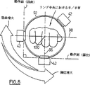
図8は使用者の手首との関連で手首CPM装置の種々の配向を説明するものであって、本発明に係わる周方向トラック上のアクチュエータの配向に依存しつつ、手首関節の伸展/屈曲から偏位に至るまで手首の動きの変化を示している;
図9は本発明に係わる足首CPM装置の斜視図であって、足首の屈曲(plantarflexion)/背屈(dorsiflexion)運動を行う場合の方向を示す図;
図10は図9に示す足首CPM装置を部分的分解した状態を示す斜視図であって、シュー組立体の詳細を示す図;
図10aは図10に示す足首CPM装置のためのシューの他の例を示す図;
図11は本発明に係わる足首CPM装置の斜視図であって、足首関節の内がえし(inversion)/外がえし(eversion)運動を行う場合の配向を示す図;
図12はコントローラー形成部品のコントロールパネルを示す平面図;
図13aは図9に示す足首CPM装置における使用者の脚の図であって、足首関節の内がえし/外がえし運動を行う場合の装置の配向との関連で、足、足首及び下部脚部の骨格構造を示す図;
図13bは、図12aと同様に、足首の足底屈曲/背屈運動を与える場合の装置の配向との関連で、足、足首及び下部脚部の骨格構造を示す図;
図14は本発明に係わるアーチ状トラックにマウントされたアクチュエータの異なる位置についての足首の運動の型を説明する図;
発明の詳細な説明
A)手首CPM装置
図1aを参照すると、手首関節の運動のための連続的受動運動(CPM)装置は20で示されている。この手首CPM装置20は、破線で24として示される使用者の前腕を受理するための腕支持部材22を含む。この前腕24は長手軸を規定している。腕支持部材22は可撓性スリーブ26を含み、このスリーブ26は2つのフック/ループ型固定用ストラップ(紐)28、30をフック32、34とで前腕の周りに固定されている。
手首CPM装置20は更に支持部材22を備えたアーチ状トラック40を含む。この支持部材22はファスナーとスタンドオフ(図示しない)によりトラック40の内側表面に固定されている。アーチ状トラック40は半円形トラックであり、図1aに示されているものは約200度の角度の円弧を形成し、患者の前腕の周りに延び得る十分に大きい直径のものとなっている。
手首CPM装置20は更にモーター駆動のアクチュエータ42を具備し、このアクチュエータ42はハウジング44と、このハウジング44に固着されたスロット付きブラケット46とを備えている。このブラケット46はトラック40上に摺動自在に装着され、アクチュエータ42がトラック上の任意の位置に位置決めされ得るように調整可能となっている。また、ブラケット46は位置調整ロック48を有し、アクチュエータ42をトラック40上の任意の位置にてロックし得るようになっている。窪み49はスロット付きブラケット46との関連でトラック40についてのロック位置を規定するものである。トラック40上のアクチュエータ42の位置はロック調整部48と摺動アクチュエータ42を離脱させ、所望の位置に設定し、係止ロック48と係合させることによりセットされる。
手首CPM装置20はシャフト50を含み、このシャフト50の基端は円形ブラケット52に取り付けられている。このブラケット52はアクチュエータ42にマウントされている。このアクチュエータ42は操作においてハウジング44内に収納されたモーター(図示しない)によりピボットするようになっている。コントローラー/電力供給部54はコード56を介してアクチュエータ42に接続され、充電可能な電池及び/又は電力アダプター58を含むものであってもよい。ハウジング44内のモーターはハウジング44との関連でシャフト50を一方から他方へピポットさせる。
手支持部材85はブラケット72に取着された半円形リング70を具備し、このブラケット72はシャフト50の先端に固定されている。このブラケット72はシャフト50に沿って摺動自在になっている。リング70とブラケット72との間にはゴムパッド又はグロメット68が設けられ、これはリングとブラケットとの間の可撓性クッションとして作用し、ブラケット72に対し撓み得るようになっている。ロック捩子74がブラケット72に対しリング70を所望の位置でロックするのに用いられている。したがって、リングがブラケットを摺動することができないが、これらの間に圧着された可撓性パッド68により前後に撓んだり、揺動し得るようになっている。手支持部材85はU字形横断部材76を含む。このU字形部材76はその端部を介して一対の支柱78に取着されている。この支柱78は半円形リング70の両端部に接続されている。横断部材76は掴み部とループを提供し、フック型締付けストラップ(帯)はこの横断部材76を被覆し、使用者の手82を横断部材76に固定させる。
シャフト50の回動の範囲は、2つの運動範囲(ROM)摺動スイッチ53(図1bに示す)を調整することによりセットすることができる。これら摺動スイッチ53はハウジング44内に配置された角度計と連動するようにしてスロット55(図1a)内に配置されている。アクチュエータ上の目盛り付マーク57は運動停止リミットスイッチ53の位置をセットする場合の参照として用いられる。これらのスイッチ53は、シャフト50のピボット運動を制限することによりシャフト50が移動し得る角度の範囲を決定するものである。
コントローラー54は3−位置スイッチ59、すなわち、オン/オフに相当する位置1;フル荷重の50%に相当する位置2;フル荷重の100%に相当する位置3、を含むコントロール回路を具備する。このコントローラー54は更に、参照によってここに含まれる米国特許第4,716,889号に開示されているモーター電流をモニターするためのリバース・オン・ロード技術を含む。アクチュエータによりピボットするシャフト50は、予め設定された値の範囲で動作し、その範囲を超えた場合は、モーターが方向を変え、シャフト50を反対方向に移動させる。もし、患者がシャフト50の動きに抵抗した場合、モーター電流が増大し、閾値電流を一旦超えると、このユニットは方向を反転する。
図2は手首CPM装置90の他の例を示すもので、腕支持部材は示されていない。この手首CPM装置90は図1aの例の半円形トラック40とは対照的に円形形状のトラック92を含む。窪み94はスロット付ブラケット46との関連でのトラック92をロックするためのロック位置を提供する。図2に実線で示すように、モーターがアクチュエータ42上のシャフト50をピボットさせたとき、駆動バーが軸96の周りにピボットし、破線で示すようにアクチュエータがトラック90上に再配置されると、駆動バーが軸98の周りにピボットする。シャフト50の先端部がトラック92との関連でピボットする距離は使用者又はオペレータが手首の治療の制限に調和するように調整ないし予めセットし、伸展(extension)、屈曲(flexion)、尺側(ulnar)及び橈骨(radial)偏位についての全範囲又は所定範囲の運動を所望に応じて行うようにする。
ヒトの関節は単一の面内、垂直な面内、又はこれらの面の組合せ内で動かすことができる。本発明による運動範囲(ROM)の原則においては、トラックに沿って単一軸駆動が配置され、その中心は操作される関節と同軸であり、関節に対しあらゆる範囲の動きを与えることができる。手首CPM装置20、90の操作上の原則は同一である。
次に、図2を参照して説明すると、矢印100はCPM機構の仮想中心を示している。これは使用時において手首関節の解剖学的中心と一致する。手首CPM装置20の仮想中心も手首関節の解剖学的中心と一致する。使用者はその腕を支持部材22(図1a)に、手首関節がCPM機構の仮想中心100と整合するようにして縛り付ける。この場合、手首関節はシャフト50とアクチュエータ42の台との間のピボット点あるいは結合と整合している。手首関節とトラックとの相対的位置は固定されたままの状態であり、アクチュエータ42の位置はトラック92に沿って変化している。図2はアクチュエータ42がトラック92に沿って摺動するとき、手首と仮想中心100との相対的位置が固定されたままの状態に保たれることを示している。アクチュエータ42がトラック92に沿って約90度の角度変位した後の状態が破線で示されている。シャフト50のアクチュエータ42に対するピボット結合は手首関節の周りにアーチを描く方向で、かつ、前腕の長手軸に実質的に垂直な面にのみ移動するよう制限させる。この場合、手首関節はこの面に浮遊し、これにより関節に対する緊張、押圧が軽減される。このようにして、関節の運動範囲全体に亘って、関節の整合が保たれる。
アクチュエータ42が図2に実線で示す偏位を生じさせる位置から破線で示す屈曲を生じさせる位置へ移動するとき、それはトラック92に沿って90度の角度移動することになる。しかし、横断部材76がブラケット72に固定されているため、同じ軸を介して横断部材76も90度の角度回転することになる。リング70は逆方向に移動し中立位置に戻され、ここで横断部材76が使用者により握られる。これは、ノブ74を緩め、半円形リング70を回動し元の位置に戻すことにより達成される。したがって、アクチュエータ42がトラック40に沿って移動するとき、手支持部材を反対方向に移動させ手首関節を中立位置に保持させることができる。
手支持部材は、リング70とブラケット72との間のゴムパッド68の存在によりアクチュエータのピボット中心に対し浮遊し得るように作製されている。この変位はアクチュエータの同軸ピボット運動と解剖学的関節の同軸ピボット運動との相違を順応させる。この僅かな変位は、関節を予め設定された範囲で移動する間において、解剖学的関節に対する押圧と緊張を軽減させる。したがって、患者がグリップ部材を掴み、関節を種々の型に動作させたとき、このグリップ部材の浮遊作用が関節に対する好ましくないストレスが加わることを防止する。この浮遊性手支持部材は、ハンドグリップが駆動部にしっかりと固着された従来の装置と比較して非常に有利となる。本発明によれば、運動の面を変化させたときでも、解剖学的整合を維持させることができる。
図3、4は図1a、2の手首CPM機構と手首関節との相対的位置関係をそれぞれ示している。ここで、CPM機構の仮想中心100が手首関節の解剖学的中心と一致していることを示している。図3に示す配向は図1aの配向に相当し、ここでアクチュエータ42は手首及び前腕の直下に位置している。ブラケット72は横断部材76を握る指の直下に位置している。この位置において、モーターがシャフト50をピボットさせたとき、手首は矢印110で示す方向に強制的に橈骨偏位され、矢印112に示す方向に尺側偏位される。図2に破線で示すアクチュエータ42の位置は手首及び手に対し伸展及び屈曲の動きを与える。この場合、使用者の前腕は図4に示すように装置内にある。この位置において、シャフト50がピボットしたとき、矢印114で示す方向の手首の伸展が達成され、また矢印116で示す方向の手首の屈曲が達成される。
図5、6は図3、4においてそれぞれ矢印5、6から見た前面図であり、純粋な尺側偏位/橈骨偏位(図5)及び純粋な伸展/屈曲動作(図6)を与えるための手首に対するアクチュエータ42の位置決めをそれぞれ示している。図7は純粋な屈曲と偏位のための動作面間に45度の角度で位置づけられたアクチュエータ42を示しており、これによりシャフト50が駆動されたとき、手首は屈曲/伸展と偏位の組合せの動きを行うことになる。図8はトラック92上のアクチュエータ42の種々の位置に対応する手首の動きの型を要約して示している。
本発明に係わる手首CPM装置は公知のCPM装置との比較において多くの利点を有する。例えば、屈曲(角度、0ないし85度)、伸展(角度、0ないし85度)のための全範囲の動き、手首関節の十分な尺側偏位/橈骨偏位、各動作の調整可能な範囲の動きなどを行うことができる。更にこの装置は単に各純粋な動作のための位置相互間の任意の位置にアクチュエータを位置決めするだけで手首の組合された軸の動作を提供することができ、屈曲から偏位へ変化させるための再組立を必要としない。このような利点は、アクチュエータを肢節と関節の周りに再度位置決めするとき、手首関節をアクチュエータ及びアクチュエータシャフトのピボット点と整合するように維持させるアーチ状のトラックを有するアクチュエータ位置決め機構によって達成される。
B)足首CPM装置
図9ないし11を参照して説明すると、足首関節の受動運動のためのCPM装置が150で示されている。この足首CPM装置150はフレーム152を含み、これに破線で示された使用者の下方脚部158と足160を受け入れるための下方脚装具154とシュー156が取り付けられている。この装具154は可撓性スリーブ162を含み、このスリーブ162はこの装具154に下方脚部158を固定するための一対のフック/ループ型固定用ストラップ(紐)164を備えている。更に、好ましくは半円形のアーチ状トラック170が図11に示すように上端部171を介して上記フレーム152に取着されている。図10にのみ示すように、輪郭を型取った脚部支持部材172がその一端を介してトラック170の内方凹み面に取着され、図11に示すように脚部支持部材172の他端は垂直支柱174の頂部に固定されている。この支柱174は、下方脚部158が装具154に固定されたとき、脚部支持部材172と下方脚部158を支持する。
アクチュエータ180にはスロット付きブラケット182が設けられ、このブラケット182はトラック170上に揺動可能にマウントされている。図9、10に示すように、バネ付勢レバーハンドル178が、0ないし90度の角度範囲に亘って、トラック170のエッジ173に沿って10度毎に形成された窪み(図示しない)と係合するようになっていて、アクチュエータをトラック上の任意の位置にロックし得るようになっている。このアクチュエータ180は、図11に187で示すピボット結合によってシャフト184にピボット結合されたモーター(図示しない)を収納している。アクチュエータが動作しているとき、モーターはL形シャフトを矢印A、Bで示す方向にピボットさせる。アクチュエータ180はモーターのための2つの前方向/逆方向ボタン185、193を含む。これらボタン185、193はアクチュエータ・ハウジングの両側に1つずつ配置されている。図9に示すようにボタン185は矢印Aで示す方向にシャフト184を上に向けて駆動させ、ボタン193は矢印Bで示す方向にシャフト184を下に向けて駆動させる。アクチュエータ180には角度計210がマウントされ、アクチュエータとの関連でシャフト184のピボット運動の範囲をセットしたりモニターしたりするための参照として機能する。
L形シャフト184は2つのリーブ186、188を具備し、その間にデスク190が介在している。シュー156はリーブ186、188にピボット的に取り付けられた足裏又は足プレート192を含む。ロックノブ194がリーブ186、188相互を締付けるために用いられている。このノブ194を緩めることによりシャフト184に対するシュー156の角度を変化させることができ、ノブ194を締付けることによりシューを選択された角度にてロックし得るようになっている。図10の部分拡大図を参照すると、シュー156は、突部157を孔159に一致させ、押圧して嵌合させ、ついでシューを足プレートに対し摺動させることにより装着される。
図10aはシュー組立体300の他の例を示している。シュー302は底部304を含み、これに一対のボス306、308が離間して挿入されていて、底部304の側方から突出している。このシュー組立体300は足プレート314を含み、これの両側中間部に第1の対のスプリングタブ又はブラケット316が鋲止めされている。このタブ316には孔318が設けられ、これにボス306が受け入れられる。他の一対のブラケット324が足プレート314の裏に設けられ、そのそれぞれにはL形スロットを有する垂直延出部が設けられ、これにボス308が嵌合するようになっている。矢印はシューと足プレートとの組立を示し、ボス308がスロット326の垂直部と係合し、ついでシュー302を足プレートに対し押し下げスロット326の水平部にボス308を嵌合させるようにしている。この場合、タブ316の孔318にボス306がピッタリ嵌り込み、その結果、シューと足プレートとが相互にロックされる。シュー302を足プレート314から取外す場合は、タブ316を横方向に引き孔318からボス306を離脱させ、上記と反対の操作を行えばよい。
アクチュエータ180は、手動棒体202が設けられたコントローラ200(図9)に電気的に接続されている。患者により操作される棒体202は親指操作ボタン204を有し、このユニットをオン/オフし得るようになっている。このコントローラ200はバッテリーで動作させるようにしてもよいし、又はアダプター206を用いて壁ソケットから電力を供給してもよい。コントローラ200は制御電子機器と充電可能なバッテリー(図示しない)を含む。
図12はコントローラ200の好ましい例のフロントパネルを示している。これにはオン/オフボタン240、第1のリミットスイッチ242、第2のリミットスイッチ244並びにそれぞれに関連させた発光ダイオード表示部246が設けられている。使用者はスイッチ204を押し足首を動かす。スイッチ204を離すことによりアクチュエータ180が停止し、又は動作範囲をプログラムさせる。図9、12を参照して説明すると、アクチュエータ180のための動作範囲をセットするには、僅か2点のプログラミングを必要とするに過ぎない。すなわち、動作範囲の始点(リミット1)と動作範囲の終点(リミット2)である。この第1の位置又はリミットはボタン185をシャフトが第1のリミット1に達するまで押し、ついでボタン185を離し、リミットボタン242を押すことによりセットされる。第2のリミットはボタン193をシャフトが第2のリミット2に達するまで押し、ついでボタン193を離し、リミットボタン244を押すことによりセットされる。コントローラは患者又は治療者により手動でセットされるこれらの2つのROMリミットを記憶する。これらリミットの値がプログラム化され、記憶されると、アーム184がこの2つの選択されたリミットの間を走行する。このコントローラ200は上述のようにリバース・オン・ロード技術を利用している。
操作において、使用者は足又は脚を足首CPM装置150内に固定する。図9に示すように、トラック170の右又は左側に上端部を介してアクチュエータ180を装着させた状態において、スイッチを入れると、シャフト184及びシュー156がそれぞれ矢印A及びBの方向に上下にピボットする。これにより或る範囲の足底屈曲/背屈がもたらされる。特に図11を参照して説明すると、サブタラ(subtalar)関節複合動作のために、アクチュエータ180がトラックの底部に位置される。これにより矢印C及びDの方向の足首の或る範囲の内がえし/外がえし動作がもたらされる。シャフト184のアクチュエータ180へのピボット結合187は足首関節の周りにアーチを描く方向で、かつ、下方脚部の長手軸に実質的に垂直な面にのみ移動するよう制限されている。このようにして関節の整合(alignment)が関節の運動範囲全体に亘って維持される。
足首CPM装置150の動作範囲は、アーチ状トラック170に沿うアクチュエータ180の位置並びに上述の動作コントローラ200でセットした動作リミットの範囲に依存する。足首CPM装置150の動作範囲を屈曲から内がえし/外がえし動作に変更するためには、使用者はアクチュエータ180上のレバーハンドル178(図9)を押しアクチュエータをトラック170に沿って所望の位置にスライドさせる。このレバーハンドル178を解放することによりアクチュエータはその位置にてロックされる。アクチュエータがその選択された位置に固定されて状態において、足プレート192及びシュー156が垂直方向に回転され、ノブ194が締付けられる。内がえし/外がえしと屈曲/伸展との組合せからなる足首関節の運動は、アクチュエータ180を0ないし90度の間の或る角度にセットし、足プレートを垂直位置にピボットさせ、シューを垂直位置で固定することにより行うことができる。
図13a及び13bは患者の脚の配置を説明するものであり、アクチュエータ180に対する下方脚部250、足首関節252及び足254の相対的配置を示している。図13aに示す位置は図11に相当するもので、足首関節の或る範囲の内がえし/外がえし動作がもたらされ、足首CPM装置150の仮想中心260が足首関節252と一致している。この場合、足首関節はシャフト184とアクチュエータ180との間のピボット結合と整合している。足首の足底屈曲/背曲動作を与えるためのアクチュエータ180の図13bに示す位置への移動においても足首関節は依然としてピボット点と整合している。
図14は足首の運動の1つの型から他の型への移り変わりをアクチュエータ180のトラック170に対する位置の関数として説明するものである。したがって、上記手首CPM装置と同様に、半円形トラックに摺動可能にマウントされたアクチュエータは足首関節の周りに位置するピボット点を維持し、その異なる周方向の位置は足首関節の運動の異なる組合せを提供することになる。
上記の装置は受動運動が2以上の面で有効な他の関節に対しても適用し得ることは当業者にとって自明であろう。したがって、手首、足首関節のためのCPM装置についてその好ましい態様、変形例を説明したが、本発明の範囲は請求の範囲並びにその均等の範囲の全ての態様を包含すべく規定されるべきものである。TECHNICAL FIELD OF THE INVENTION
The present invention relates to a continuous passive exercise device for joint exercise therapy, and more particularly to a continuous passive exercise device for treatment of wrist and ankle joints.
Background of the Invention
It has recently become clear that rehabilitation and treatment of damaged joints is facilitated by the adoption of continuous passive movement (CPM) of the joint. This continuous passive motion can induce certain limb joint movements without the need for muscle coordination or control by the patient. Many studies have shown that in CPM of various joints, healing or recovery time is accelerated, healing is accelerated, and more importantly, sufficient joint movement is ensured at the end of the course of treatment. It was revealed. Therefore, joint rehabilitation using continuous passive exercise therapy has become an important method for the treatment of damaged joints.
Various types of devices and instruments for wrist, ankle and elbow joint movements are known. For example, US Pat. No. 4,538,595 discloses several passive motion devices for wrist, ankle and elbow motions. 1 to 4 show a wrist exercise device in which an actuator (actuating device) is attached to a forearm brace assembly. An actuator arm extends from the actuator to the hand brace and a hand extension / flexion movement is performed during operation. In the elbow joint exercise apparatus shown in FIGS. 18, 19, and 24, the angle of the forearm and the hand with respect to the longitudinal axis of the upper arm is adjusted during the movement of the elbow joint using a circumferential track. ing. In the ankle joint exercise apparatus shown in FIGS. 8 to 11, the actuator is attached to the upper leg orthosis assembly, the actuator rod is attached to the foot support member, and the dorsiflexion / extension movement is performed. . The radial position of the foot relative to the longitudinal axis of the lower leg can be adjusted as shown in FIG.
U.S. Pat. No. 4,650,183 discloses an exercise device for foot and ankle joints. This device is used for exercise and is also used to evaluate ankle joint function. This device consists of a bench on which the user sits during use, a pivotally mounted foot pedal, and a hydraulic cylinder attached to the foot pedal to provide resistance.
US Pat. No. 5,067,479 discloses a CPM device for the treatment of wrist joints. The device has a telescopic rod slidably mounted in a tubular shaft pivotally mounted on the base. One end of the shaft is pivotally attached to an eccentric transmission, which has wheels that are driven by a motor supported on the base. The base is tied to the upper part of the patient's wrist with a string. The other end of the shaft is connected to a grip part that a patient can grasp. In operation, the wheel rotates to extend the rod in a telescoping manner and rotate it so that the hand moves toward the wrist. Different types of wrist movement can be performed by adjusting the alignment of the motor storage assembly.
U.S. Pat. No. 5,170,776 discloses a device directed to passive articulation of the foot. This device comprises a footrest connected to various guide rods, screws, bearings and motors, and a movable base.
U.S. Pat. No. 5,352,185 discloses an ankle exercise device, which is provided with a frame with a support and a shoe for receiving a user's lower leg and foot, respectively. . This device requires two motors (8, 9 in FIG. 1), one of which is used to rotate part of the device and provide plantar flexion / back extension, the other one One pivots the other part of the device to cause prolapse / pronation of the foot in relation to the lower leg.
It would be highly advantageous to have a CPM device that can move the joint over the full range of physiological movements. Such functions can be applied for signs, maximum potential for the patient. Most joints in humans move through one or more axes, and some joints move through three axes, such as the shoulder, waist, and so on. The main drawback of many known CPM devices is that the joint can only be set to move through one axis at a time. In a CPM device, it is not practical to use two or more actuators so that the joint moves through two or more axes at a time because of restrictions on the size and weight of the device.
Accordingly, there is a need for a joint therapy exercise device that can be applied to various types of joints and that can move the joints in a full range via more than one axis at a time.
Summary of the Invention
The present invention seeks to provide an apparatus for providing continuous passive motion (CPM) to an anatomical joint.
That is, the device includes a first support member (22) engageable with the first limb node on one side of the joint, and a first support member (22) engageable with the second limb node on the other side of the joint. 2 support members (85). The CPM device includes an actuator (42) and a shaft (50) having a distal end portion and a proximal end portion. The shaft (50) is pivotally connected to the actuator (42) via its proximal end. The actuator (42) can pivot the shaft (52) to provide lateral movement. The device includes an arcuate track (40) attached to the first support member (22) and the first limb segment. Around At least partially Is the size to enclose It is characterized by that. The actuator (42) is adjustably mounted on the arched track (40) so that the actuator (42) can move while drawing an arch around the joint. The CPM device includes a locking means (48) for removably locking the actuator (42) at a predetermined position with respect to the arched track (40). Since the second support member (85) is attached to the tip of the shaft (50) in an adjustable manner, the mounting position of the second support member (85) to the shaft (50) is Adjustment is possible according to the circumferential position of the actuator (42) with respect to the node.
In this aspect of the invention, the actuator (42) is slidably mounted on the arcuate track (40), and the user's limb node and the actuator (42) held in the CPM device are When moved about the first limb section, the pivot coupling of the shaft (50) to the actuator (42) moves in a plane substantially perpendicular to the longitudinal axis of the first limb section to move the first limb section. Pass through the joint.
In another aspect, the present invention provides an apparatus for providing continuous passive motion to an ankle joint. The ankle CPM device includes a frame (152) and a leg support member (172) attached to the frame (152) for supporting a user's lower leg. The leg support member (172) includes a harness (162) for holding the lower leg portion therein. The lower leg defines a longitudinal axis. The ankle CPM device includes an arched track (170) attached to the frame (152) and having a dimension that extends at least partially around the lower leg. An actuator (180) is adjustably mounted on the arcuate track (170) and locks the actuator (180) around the lower leg at a selected position on the arcuate track (170). A locking mechanism (178). The ankle CPM device includes a shaft (184) having a proximal end and a distal end. The shaft (184) is pivotally coupled to the actuator (180) at its proximal end, and the actuator (180) can pivot the shaft (184) to provide lateral movement. The ankle CPM device includes a foot support member (156) pivotally attached to the distal end of the shaft (184) to receive a user's foot. In use, the pivoting movement of the shaft provides movement of the ankle joint.
[Brief description of the drawings]
Hereinafter, the continuous passive motion apparatus according to the present invention will be described with reference to the accompanying drawings, which are merely examples.
FIG. 1a is a perspective view of a continuous passive motion (CPM) device for wrist joint motion constructed in accordance with the present invention with the hand and arm engaged with the device;
1b is a plan view seen from the
FIG. 2 is a perspective view showing another example of a CPM device for wrist joint movement, in which the arm support means is lacking, and the device is shown in two orientations, of which the solid line is The orientation of the device giving an ulnar / radial deflection of the wrist joint, the broken line showing the orientation of the device giving the wrist joint extension and flexion;
FIG. 3 is a plan view of the wrist CPM device of FIG. 1a showing the relative positional relationship of the skeletal structure of the hand and wrist with respect to the device oriented to provide ulnar / radial displacement of the wrist joint;
FIG. 4 is a side view of the wrist CPM device of FIG. 1a showing the relative positional relationship of the hand and wrist skeletal structure with respect to a device oriented to provide wrist joint extension and flexion;
FIG. 5 is a front view seen from the direction of the
6 is a front view seen from the direction of
FIG. 7 shows a wrist CPM device, similar to FIGS. 5 and 6, showing the orientation of the device giving a combination of wrist joint extension / flexion and ulnar / radial displacement;
FIG. 8 illustrates the various orientations of the wrist CPM device in relation to the user's wrist, from the extension / flexion of the wrist joint, depending on the orientation of the actuator on the circumferential track according to the present invention. Shows changes in wrist movements up to displacement;
FIG. 9 is a perspective view of an ankle CPM device according to the present invention, showing a direction when performing an ankle flexion / dorsiflexion movement;
10 is a perspective view showing a state in which the ankle CPM device shown in FIG. 9 is partially disassembled, and shows details of the shoe assembly;
10a shows another example of a shoe for the ankle CPM device shown in FIG. 10;
FIG. 11 is a perspective view of an ankle CPM device according to the present invention, showing the orientation when performing an inversion / eversion movement of the ankle joint;
FIG. 12 is a plan view showing a control panel of a controller forming part;
FIG. 13a is a view of the user's leg in the ankle CPM device shown in FIG. 9 in relation to the orientation of the device when performing an internal / external movement of the ankle joint. Figure showing the skeletal structure of the lower leg;
FIG. 13b shows the skeletal structure of the foot, ankle and lower leg in relation to the orientation of the device when providing ankle plantar flexion / dorsiflexion motion, similar to FIG. 12a;
FIG. 14 is a diagram illustrating an ankle motion pattern for different positions of an actuator mounted on an arcuate track according to the present invention;
Detailed Description of the Invention
A) Wrist CPM device
Referring to FIG. 1 a, a continuous passive motion (CPM) device for wrist joint motion is indicated at 20. This
The
The
The
The range of rotation of the
The
FIG. 2 shows another example of the
The human joint can be moved in a single plane, a vertical plane, or a combination of these planes. In the range of motion (ROM) according to the invention, a single axis drive is arranged along the track, the center of which is coaxial with the joint to be manipulated and can give any range of motion to the joint. The operating principles of the
Next, referring to FIG. 2, the
When the
The hand support member is made so that it can float with respect to the pivot center of the actuator due to the presence of the
3 and 4 show the relative positional relationship between the wrist CPM mechanism and the wrist joint of FIGS. Here, it is shown that the
FIGS. 5 and 6 are front views as seen from
The wrist CPM device according to the present invention has many advantages over known CPM devices. For example, full range of movement for flexion (angle, 0 to 85 degrees), extension (angle, 0 to 85 degrees), sufficient ulnar / radial displacement of wrist joint, adjustable range of each movement Can be moved. In addition, the device can provide movement of the combined shaft of the wrist simply by positioning the actuator at any position between the positions for each pure movement, for changing from flexion to deflection. Does not require reassembly. Such an advantage is achieved by an actuator positioning mechanism having an arched track that keeps the wrist joint aligned with the pivot point of the actuator and actuator shaft when the actuator is repositioned around the limbs and joints. .
B) Ankle CPM device
Referring to FIGS. 9-11, a CPM device for passive movement of the ankle joint is shown at 150. The
The
The L-shaped
FIG. 10 a shows another example of the
The
FIG. 12 shows a front panel of a preferred example of the
In operation, the user secures the foot or leg within the
The range of motion of the
FIGS. 13a and 13b illustrate the placement of the patient's legs and show the relative placement of the
FIG. 14 illustrates the transition of one type of ankle movement from another type as a function of the position of the
It will be apparent to those skilled in the art that the device described above can be applied to other joints where passive motion is effective in more than one aspect. Accordingly, the preferred embodiments and modifications of the CPM device for wrist and ankle joints have been described. However, the scope of the present invention should be defined to include all the embodiments of the claims and their equivalents. is there.
Claims (21)
関節の一方の側において第1の肢節部に係合可能な第1の支持部材(22)と、関節の他方の側において第2の肢節部に係合可能な第2の支持部材(85)と、アクチュエータ(42)と、先端部と基端部を有するシャフト(50)と、を備えており、
前記シャフト(50)がその基端部を介してアクチュエータ(42)にピボット結合され、前記アクチュエータ(42)はシャフト(52)をピボットさせて横向きの運動を与えることができる装置において、
アーチ状トラック(40)が前記第1の支持部材(22)に取り付けられていて前記第1の肢節部の周りを少なくとも部分的に囲む大きさであり、
前記アクチュエータ(42)が前記アーチ状トラック(40)に調整可能にマウントされることにより、前記アクチュエータ(42)が前記関節を中心としてアーチを描いて動くことができるようにされており、
前記装置が、前記アクチュエータ(42)を前記アーチ状トラック(40)に対して所定の位置に着脱可能にロックするためのロック手段(48)を備え、
前記第2の支持部材(85)がシャフト(50)の先端部に調整可能に取着されていることにより、前記第2の支持部材(85)の前記シャフト(50)への取り付け位置が、前記肢節部に対するアクチュエータの周方向位置に応じて調整可能となっていることを特徴とする装置。A device for providing continuous passive motion to an anatomical joint,
A first support member (22) engageable with the first limb node on one side of the joint and a second support member (22) engageable with the second limb node on the other side of the joint 85), an actuator (42), and a shaft (50) having a distal end portion and a proximal end portion,
In an apparatus wherein the shaft (50) is pivotally coupled to an actuator (42) via its proximal end, the actuator (42) pivoting the shaft (52) to provide lateral motion;
An arcuate track (40) is attached to the first support member (22) and is sized to at least partially surround the first limb segment;
The actuator (42) is adjustably mounted on the arched track (40) so that the actuator (42) can move around an arch around the joint;
The device comprises locking means (48) for releasably locking the actuator (42) in place with respect to the arched track (40);
Since the second support member (85) is attached to the tip of the shaft (50) in an adjustable manner, the mounting position of the second support member (85) to the shaft (50) is The device can be adjusted according to the circumferential position of the actuator with respect to the limb segment.
フレーム(152)および、該フレーム(152)に取り付けられ下方脚部を支持するための脚支持部材(172)と、
前記フレーム(152)に取り付けられ、下方脚部の周りに少なくとも部分的に延出する寸法を有するアーチ状トラック(170)と、
基端部および先端部を有するシャフト(184)と、
使用者の足を受け入れられるように前記シャフト(184)の先端部にピボット可能に取り付けられた足支持部材(156)と、を備える装置において、
前記脚支持部材(172)は前記下方脚部を内部に保持するためのハーネス(162)を備え、前記下方脚部が長手軸を画定しており、
アクチュエータ(180)が前記アーチ状トラック(170)に調整可能にマウントされており、前記下方脚部の周りで、アーチ状トラック(170)上の選択された位置にてアクチュエータ(180)をロックするためのロック機構(178)を備えており、
前記シャフト(184)はその基端部において前記アクチュエータ(180)にピボット結合されており、前記アクチュエータ(180)は前記シャフト(184)をピボットさせて横向きの運動を与えることができ、
使用時には前記シャフトのピボット運動が前記足首関節の運動を与える装置。A device for applying continuous passive motion to the ankle joint,
A frame (152) and a leg support member (172) attached to the frame (152) for supporting the lower leg;
An arcuate track (170) attached to the frame (152) and having a dimension extending at least partially around a lower leg;
A shaft (184) having a proximal end and a distal end;
A foot support member (156) pivotally attached to the distal end of the shaft (184) for receiving a user's foot;
The leg support member (172) includes a harness (162) for holding the lower leg portion therein, and the lower leg portion defines a longitudinal axis;
An actuator (180) is adjustably mounted on the arcuate track (170) and locks the actuator (180) around the lower leg at a selected position on the arcuate track (170). A locking mechanism (178) for
The shaft (184) is pivotally coupled to the actuator (180) at its proximal end, and the actuator (180) can pivot the shaft (184) to provide lateral movement;
A device in which the pivoting movement of the shaft gives the movement of the ankle joint when in use.
Applications Claiming Priority (5)
| Application Number | Priority Date | Filing Date | Title |
|---|---|---|---|
| CA 2163303 CA2163303C (en) | 1995-11-20 | 1995-11-20 | Continuous passive motion devices for joints |
| US08/561,193 | 1995-11-21 | ||
| US08/561,193 US5738636A (en) | 1995-11-20 | 1995-11-21 | Continuous passive motion devices for joints |
| US2,163,303 | 1995-11-21 | ||
| PCT/CA1996/000746 WO1997018787A1 (en) | 1995-11-20 | 1996-11-14 | Continuous passive motion devices for joints |
Publications (2)
| Publication Number | Publication Date |
|---|---|
| JP2000500368A JP2000500368A (en) | 2000-01-18 |
| JP3884077B2 true JP3884077B2 (en) | 2007-02-21 |
Family
ID=25678223
Family Applications (1)
| Application Number | Title | Priority Date | Filing Date |
|---|---|---|---|
| JP51924697A Expired - Fee Related JP3884077B2 (en) | 1995-11-20 | 1996-11-14 | Continuous passive motion device for joints |
Country Status (7)
| Country | Link |
|---|---|
| US (1) | US5738636A (en) |
| EP (1) | EP0863737B1 (en) |
| JP (1) | JP3884077B2 (en) |
| AT (1) | ATE196243T1 (en) |
| AU (1) | AU7488196A (en) |
| DE (1) | DE69610326T2 (en) |
| WO (1) | WO1997018787A1 (en) |
Cited By (4)
| Publication number | Priority date | Publication date | Assignee | Title |
|---|---|---|---|---|
| JP2010529874A (en) * | 2007-06-12 | 2010-09-02 | コミッサリア ア レネルジー アトミーク エ オ ゼネルジ ザルタナテイヴ | Forearm rotation mechanism and straightener including the mechanism |
| WO2014092076A1 (en) * | 2012-12-14 | 2014-06-19 | 国立大学法人鹿児島大学 | Hemiplegic forearm function recovery training device |
| KR101465128B1 (en) * | 2013-05-03 | 2014-11-25 | 권대규 | Apparatus of exercise medical therapy for orthosis |
| KR101481455B1 (en) | 2013-05-02 | 2015-01-13 | 삼육대학교산학협력단 | Hemiplegia patient upper limp/lower limp physical therapy apparatus based on virtual reality influencing on muscular strength and brain activity |
Families Citing this family (122)
| Publication number | Priority date | Publication date | Assignee | Title |
|---|---|---|---|---|
| US6146341A (en) * | 1998-07-15 | 2000-11-14 | M-E-System Inc. | Continuously and externally driven motion training device of joint |
| US6592085B2 (en) * | 2000-01-07 | 2003-07-15 | Koichi Iwata | Armrest apparatus |
| JP2003526469A (en) * | 2000-03-14 | 2003-09-09 | オーサーハブ インコーポレーテッド | Control device for therapeutic joint mobilization |
| AU2001294525A1 (en) | 2000-09-06 | 2002-03-22 | Johns Hopkins University | Quantification of muscle tone |
| US6506172B1 (en) * | 2000-10-10 | 2003-01-14 | Dynasplint Systems, Inc. | Supinator/pronator therapy system to bring mobility to wrist, forearm and/or elbow |
| US20030060339A1 (en) * | 2001-09-18 | 2003-03-27 | Sundaram Ravikumar | Soleus pump |
| EP1496822B1 (en) * | 2002-04-10 | 2018-08-29 | KCI Medical Resources | Access openings in vacuum bandage |
| JP4527929B2 (en) * | 2002-05-08 | 2010-08-18 | 衛 光石 | Reduction device |
| ES2255667T3 (en) * | 2002-09-12 | 2006-07-01 | Universiteit Gent | ORTHOPEDIC SUPPORT FOR ARM AND SHOULDER. |
| US8425579B1 (en) * | 2002-10-08 | 2013-04-23 | Vitalwear, Inc. | Therapeutic knee brace for a contrast therapy system |
| US7066896B1 (en) | 2002-11-12 | 2006-06-27 | Kiselik Daniel R | Interactive apparatus and method for developing ability in the neuromuscular system |
| US20040243027A1 (en) * | 2003-04-21 | 2004-12-02 | Hook Steven D. | Repetitive motion exercise therapy device and method of treatment using same |
| FR2860713B1 (en) * | 2003-10-09 | 2006-06-02 | Abilityone Kinetec Sa | PASSIVE MOBILIZATION SPINDLE OF THE ANKLE JOINT |
| EP1602330A1 (en) * | 2004-06-04 | 2005-12-07 | Universite Libre De Bruxelles | Medical device adapted to the monitoring of limb muscle behaviour in patients |
| US7537547B1 (en) * | 2004-08-05 | 2009-05-26 | Hosick Colton D | Forearm supination device for bicep musculature development |
| WO2006037101A2 (en) * | 2004-09-27 | 2006-04-06 | Massachusetts Institute Of Technology | Ankle interface |
| JP2006247280A (en) * | 2005-03-14 | 2006-09-21 | Osaka Univ | Upper limb rehabilitation device |
| JP4811868B2 (en) * | 2006-09-13 | 2011-11-09 | 国立大学法人岐阜大学 | Upper limb finger function recovery training device |
| WO2008047355A2 (en) * | 2006-10-16 | 2008-04-24 | Motorika Limited | Methods and gyroscopic apparatus for rehabilitation training |
| US20090054820A1 (en) * | 2007-02-28 | 2009-02-26 | Weltner Thomas R | Static progressive pronation supination splint |
| US7575541B2 (en) * | 2007-03-14 | 2009-08-18 | Samuel Chen | Spine stretch machine |
| US7854708B2 (en) * | 2007-05-22 | 2010-12-21 | Kai Yu Tong | Multiple joint linkage device |
| KR101718345B1 (en) * | 2007-12-26 | 2017-03-21 | 렉스 바이오닉스 리미티드 | Mobility aid |
| DE102008012996A1 (en) * | 2008-03-07 | 2009-09-17 | Pohlig Gmbh | Orthese for correction of joint misalignment, has orthese joint enabling movement of shell parts relative to each other in desired joint position, and shell parts connected with moving device that moves shell parts relative to each other |
| ES2539521T3 (en) * | 2008-10-10 | 2015-07-01 | Fundacion Fatronik | Universal haptic drive system |
| US20110237400A1 (en) * | 2008-12-02 | 2011-09-29 | Marcus James King | Arm Exercise Device and System |
| US8696606B2 (en) * | 2009-09-28 | 2014-04-15 | Continuous MotionFlow, LLC | Passive motion machine with integrated mechanical DVT prophylactic therapy |
| US9108080B2 (en) * | 2011-03-11 | 2015-08-18 | For You, Inc. | Orthosis machine |
| US8845560B1 (en) | 2011-06-17 | 2014-09-30 | Antonio Hernandez | Physical therapy chair |
| CN102389360B (en) * | 2011-07-22 | 2013-11-27 | 南京市鼓楼医院 | Ankle flexion and extension exerciser |
| US9144529B2 (en) * | 2011-07-27 | 2015-09-29 | Stephen Lynn Culver | Range of motion assistant |
| TWI412355B (en) * | 2011-09-27 | 2013-10-21 | Univ Nat Cheng Kung | Hand rehabilitation device |
| KR101305341B1 (en) | 2012-05-18 | 2013-09-06 | 동의대학교 산학협력단 | Apparatus for rehabilitation training of wrist and ankle |
| KR101422395B1 (en) * | 2013-02-25 | 2014-07-22 | 인제대학교 산학협력단 | Automatic calf muscle lengthening exercise apparatus |
| CN103433937A (en) * | 2013-08-20 | 2013-12-11 | 华南理工大学 | Mechanical type wrist movement capture device |
| US11826274B1 (en) | 2013-12-12 | 2023-11-28 | Ermi Llc | Devices and methods for assisting extension and/or flexion |
| KR101489795B1 (en) | 2013-12-18 | 2015-02-04 | (주)힐닉스 | Rehabilitating Exercise Apparatus for Upper and Lower Extremity |
| US10123929B2 (en) * | 2014-06-17 | 2018-11-13 | Colorado School Of Mines | Wrist and forearm exoskeleton |
| CN104814856B (en) * | 2015-05-09 | 2017-04-12 | 安阳工学院 | Two-freedom-degree upper limb rehabilitation training device |
| BR102016022139B1 (en) * | 2016-09-26 | 2020-12-08 | Antonio Massato Makiyama | equipment for motor rehabilitation of upper and lower limbs |
| CN106859688B (en) * | 2016-12-30 | 2020-07-28 | 丽水市人民医院 | Ankle joint internal and external rotation stress position maintaining device |
| CN106726353B (en) * | 2017-01-08 | 2019-04-12 | 北京工业大学 | It is a kind of based on adaptive wrist joint rehabilitation training device in parallel |
| RU2658760C1 (en) * | 2017-01-09 | 2018-06-22 | Общество с ограниченной ответственностью Научно-внедренческое предприятие "ОРБИТА", (ООО НВП "ОРБИТА") | Mechanotherapy device for developing ankle mobility |
| US10195097B1 (en) | 2017-01-13 | 2019-02-05 | Gaetano Cimo | Neuromuscular plasticity apparatus and method using same |
| US11583463B2 (en) * | 2017-08-31 | 2023-02-21 | Kagoshima University | Hemiplegic forearm function recovery training device and method |
| GB201800267D0 (en) * | 2018-01-08 | 2018-02-21 | Bae Systems Plc | Patient rehabilitation device |
| CN109223432B (en) * | 2018-08-01 | 2021-03-26 | 广州中医药大学(广州中医药研究院) | Intelligent robot for wrist joint rehabilitation |
| CN109223437B (en) * | 2018-08-22 | 2020-08-18 | 韩晗 | A multi-functional rehabilitation and nursing device for orthopedic patient |
| CN109394475B (en) * | 2018-11-15 | 2023-10-03 | 南昌大学 | Five-finger rehabilitation manipulator capable of autonomously adjusting and disassembling finger spacing |
| CN109394477B (en) * | 2018-12-10 | 2021-03-16 | 北京工业大学 | A 2-SPU/RR parallel pneumatic wrist rehabilitation device |
| US11541274B2 (en) | 2019-03-11 | 2023-01-03 | Rom Technologies, Inc. | System, method and apparatus for electrically actuated pedal for an exercise or rehabilitation machine |
| US11185735B2 (en) | 2019-03-11 | 2021-11-30 | Rom Technologies, Inc. | System, method and apparatus for adjustable pedal crank |
| US12029940B2 (en) * | 2019-03-11 | 2024-07-09 | Rom Technologies, Inc. | Single sensor wearable device for monitoring joint extension and flexion |
| US11957960B2 (en) | 2019-05-10 | 2024-04-16 | Rehab2Fit Technologies Inc. | Method and system for using artificial intelligence to adjust pedal resistance |
| US12102878B2 (en) | 2019-05-10 | 2024-10-01 | Rehab2Fit Technologies, Inc. | Method and system for using artificial intelligence to determine a user's progress during interval training |
| US11904207B2 (en) | 2019-05-10 | 2024-02-20 | Rehab2Fit Technologies, Inc. | Method and system for using artificial intelligence to present a user interface representing a user's progress in various domains |
| US11433276B2 (en) | 2019-05-10 | 2022-09-06 | Rehab2Fit Technologies, Inc. | Method and system for using artificial intelligence to independently adjust resistance of pedals based on leg strength |
| US11801423B2 (en) | 2019-05-10 | 2023-10-31 | Rehab2Fit Technologies, Inc. | Method and system for using artificial intelligence to interact with a user of an exercise device during an exercise session |
| CN110074946B (en) * | 2019-06-17 | 2021-02-09 | 山东海天智能工程有限公司 | A wrist function rehabilitation training device |
| US11071597B2 (en) | 2019-10-03 | 2021-07-27 | Rom Technologies, Inc. | Telemedicine for orthopedic treatment |
| US12402804B2 (en) | 2019-09-17 | 2025-09-02 | Rom Technologies, Inc. | Wearable device for coupling to a user, and measuring and monitoring user activity |
| US11701548B2 (en) | 2019-10-07 | 2023-07-18 | Rom Technologies, Inc. | Computer-implemented questionnaire for orthopedic treatment |
| US20230245750A1 (en) | 2019-10-03 | 2023-08-03 | Rom Technologies, Inc. | Systems and methods for using elliptical machine to perform cardiovascular rehabilitation |
| US11915816B2 (en) | 2019-10-03 | 2024-02-27 | Rom Technologies, Inc. | Systems and methods of using artificial intelligence and machine learning in a telemedical environment to predict user disease states |
| US11756666B2 (en) | 2019-10-03 | 2023-09-12 | Rom Technologies, Inc. | Systems and methods to enable communication detection between devices and performance of a preventative action |
| US11515028B2 (en) | 2019-10-03 | 2022-11-29 | Rom Technologies, Inc. | Method and system for using artificial intelligence and machine learning to create optimal treatment plans based on monetary value amount generated and/or patient outcome |
| US11069436B2 (en) | 2019-10-03 | 2021-07-20 | Rom Technologies, Inc. | System and method for use of telemedicine-enabled rehabilitative hardware and for encouraging rehabilitative compliance through patient-based virtual shared sessions with patient-enabled mutual encouragement across simulated social networks |
| US12191018B2 (en) | 2019-10-03 | 2025-01-07 | Rom Technologies, Inc. | System and method for using artificial intelligence in telemedicine-enabled hardware to optimize rehabilitative routines capable of enabling remote rehabilitative compliance |
| US12224052B2 (en) | 2019-10-03 | 2025-02-11 | Rom Technologies, Inc. | System and method for using AI, machine learning and telemedicine for long-term care via an electromechanical machine |
| US11887717B2 (en) | 2019-10-03 | 2024-01-30 | Rom Technologies, Inc. | System and method for using AI, machine learning and telemedicine to perform pulmonary rehabilitation via an electromechanical machine |
| US11139060B2 (en) | 2019-10-03 | 2021-10-05 | Rom Technologies, Inc. | Method and system for creating an immersive enhanced reality-driven exercise experience for a user |
| US11830601B2 (en) | 2019-10-03 | 2023-11-28 | Rom Technologies, Inc. | System and method for facilitating cardiac rehabilitation among eligible users |
| US11087865B2 (en) | 2019-10-03 | 2021-08-10 | Rom Technologies, Inc. | System and method for use of treatment device to reduce pain medication dependency |
| US11923065B2 (en) | 2019-10-03 | 2024-03-05 | Rom Technologies, Inc. | Systems and methods for using artificial intelligence and machine learning to detect abnormal heart rhythms of a user performing a treatment plan with an electromechanical machine |
| US11317975B2 (en) | 2019-10-03 | 2022-05-03 | Rom Technologies, Inc. | Method and system for treating patients via telemedicine using sensor data from rehabilitation or exercise equipment |
| US11978559B2 (en) | 2019-10-03 | 2024-05-07 | Rom Technologies, Inc. | Systems and methods for remotely-enabled identification of a user infection |
| US12420145B2 (en) | 2019-10-03 | 2025-09-23 | Rom Technologies, Inc. | Systems and methods of using artificial intelligence and machine learning for generating alignment plans to align a user with an imaging sensor during a treatment session |
| US11955220B2 (en) | 2019-10-03 | 2024-04-09 | Rom Technologies, Inc. | System and method for using AI/ML and telemedicine for invasive surgical treatment to determine a cardiac treatment plan that uses an electromechanical machine |
| US11515021B2 (en) | 2019-10-03 | 2022-11-29 | Rom Technologies, Inc. | Method and system to analytically optimize telehealth practice-based billing processes and revenue while enabling regulatory compliance |
| US11282604B2 (en) | 2019-10-03 | 2022-03-22 | Rom Technologies, Inc. | Method and system for use of telemedicine-enabled rehabilitative equipment for prediction of secondary disease |
| US11961603B2 (en) | 2019-10-03 | 2024-04-16 | Rom Technologies, Inc. | System and method for using AI ML and telemedicine to perform bariatric rehabilitation via an electromechanical machine |
| US12427376B2 (en) | 2019-10-03 | 2025-09-30 | Rom Technologies, Inc. | Systems and methods for an artificial intelligence engine to optimize a peak performance |
| US12176089B2 (en) | 2019-10-03 | 2024-12-24 | Rom Technologies, Inc. | System and method for using AI ML and telemedicine for cardio-oncologic rehabilitation via an electromechanical machine |
| US12230381B2 (en) | 2019-10-03 | 2025-02-18 | Rom Technologies, Inc. | System and method for an enhanced healthcare professional user interface displaying measurement information for a plurality of users |
| US12347543B2 (en) | 2019-10-03 | 2025-07-01 | Rom Technologies, Inc. | Systems and methods for using artificial intelligence to implement a cardio protocol via a relay-based system |
| US12469587B2 (en) | 2019-10-03 | 2025-11-11 | Rom Technologies, Inc. | Systems and methods for assigning healthcare professionals to remotely monitor users performing treatment plans on electromechanical machines |
| US11955223B2 (en) | 2019-10-03 | 2024-04-09 | Rom Technologies, Inc. | System and method for using artificial intelligence and machine learning to provide an enhanced user interface presenting data pertaining to cardiac health, bariatric health, pulmonary health, and/or cardio-oncologic health for the purpose of performing preventative actions |
| US12327623B2 (en) | 2019-10-03 | 2025-06-10 | Rom Technologies, Inc. | System and method for processing medical claims |
| US20210134412A1 (en) | 2019-10-03 | 2021-05-06 | Rom Technologies, Inc. | System and method for processing medical claims using biometric signatures |
| US12087426B2 (en) | 2019-10-03 | 2024-09-10 | Rom Technologies, Inc. | Systems and methods for using AI ML to predict, based on data analytics or big data, an optimal number or range of rehabilitation sessions for a user |
| US12062425B2 (en) | 2019-10-03 | 2024-08-13 | Rom Technologies, Inc. | System and method for implementing a cardiac rehabilitation protocol by using artificial intelligence and standardized measurements |
| US12020799B2 (en) | 2019-10-03 | 2024-06-25 | Rom Technologies, Inc. | Rowing machines, systems including rowing machines, and methods for using rowing machines to perform treatment plans for rehabilitation |
| US11282599B2 (en) | 2019-10-03 | 2022-03-22 | Rom Technologies, Inc. | System and method for use of telemedicine-enabled rehabilitative hardware and for encouragement of rehabilitative compliance through patient-based virtual shared sessions |
| US12020800B2 (en) | 2019-10-03 | 2024-06-25 | Rom Technologies, Inc. | System and method for using AI/ML and telemedicine to integrate rehabilitation for a plurality of comorbid conditions |
| US11270795B2 (en) | 2019-10-03 | 2022-03-08 | Rom Technologies, Inc. | Method and system for enabling physician-smart virtual conference rooms for use in a telehealth context |
| US12230382B2 (en) | 2019-10-03 | 2025-02-18 | Rom Technologies, Inc. | Systems and methods for using artificial intelligence and machine learning to predict a probability of an undesired medical event occurring during a treatment plan |
| US11955222B2 (en) | 2019-10-03 | 2024-04-09 | Rom Technologies, Inc. | System and method for determining, based on advanced metrics of actual performance of an electromechanical machine, medical procedure eligibility in order to ascertain survivability rates and measures of quality-of-life criteria |
| US11282608B2 (en) | 2019-10-03 | 2022-03-22 | Rom Technologies, Inc. | Method and system for using artificial intelligence and machine learning to provide recommendations to a healthcare provider in or near real-time during a telemedicine session |
| US11075000B2 (en) | 2019-10-03 | 2021-07-27 | Rom Technologies, Inc. | Method and system for using virtual avatars associated with medical professionals during exercise sessions |
| US11955221B2 (en) | 2019-10-03 | 2024-04-09 | Rom Technologies, Inc. | System and method for using AI/ML to generate treatment plans to stimulate preferred angiogenesis |
| US12220201B2 (en) | 2019-10-03 | 2025-02-11 | Rom Technologies, Inc. | Remote examination through augmented reality |
| US12539446B2 (en) | 2019-10-03 | 2026-02-03 | Rom Technologies, Inc. | Method and system for using sensors to optimize a user treatment plan in a telemedicine environment |
| US12154672B2 (en) | 2019-10-03 | 2024-11-26 | Rom Technologies, Inc. | Method and system for implementing dynamic treatment environments based on patient information |
| US12380984B2 (en) | 2019-10-03 | 2025-08-05 | Rom Technologies, Inc. | Systems and methods for using artificial intelligence and machine learning to generate treatment plans having dynamically tailored cardiac protocols for users to manage a state of an electromechanical machine |
| US11101028B2 (en) | 2019-10-03 | 2021-08-24 | Rom Technologies, Inc. | Method and system using artificial intelligence to monitor user characteristics during a telemedicine session |
| US12246222B2 (en) | 2019-10-03 | 2025-03-11 | Rom Technologies, Inc. | Method and system for using artificial intelligence to assign patients to cohorts and dynamically controlling a treatment apparatus based on the assignment during an adaptive telemedical session |
| US12100499B2 (en) | 2020-08-06 | 2024-09-24 | Rom Technologies, Inc. | Method and system for using artificial intelligence and machine learning to create optimal treatment plans based on monetary value amount generated and/or patient outcome |
| US11915815B2 (en) | 2019-10-03 | 2024-02-27 | Rom Technologies, Inc. | System and method for using artificial intelligence and machine learning and generic risk factors to improve cardiovascular health such that the need for additional cardiac interventions is mitigated |
| US12420143B1 (en) | 2019-10-03 | 2025-09-23 | Rom Technologies, Inc. | System and method for enabling residentially-based cardiac rehabilitation by using an electromechanical machine and educational content to mitigate risk factors and optimize user behavior |
| US11265234B2 (en) | 2019-10-03 | 2022-03-01 | Rom Technologies, Inc. | System and method for transmitting data and ordering asynchronous data |
| US12478837B2 (en) | 2019-10-03 | 2025-11-25 | Rom Technologies, Inc. | Method and system for monitoring actual patient treatment progress using sensor data |
| US12150792B2 (en) | 2019-10-03 | 2024-11-26 | Rom Technologies, Inc. | Augmented reality placement of goniometer or other sensors |
| US11534358B2 (en) | 2019-10-11 | 2022-12-27 | Neurolutions, Inc. | Orthosis systems and rehabilitation of impaired body parts |
| US11826613B2 (en) | 2019-10-21 | 2023-11-28 | Rom Technologies, Inc. | Persuasive motivation for orthopedic treatment |
| US12424319B2 (en) | 2019-11-06 | 2025-09-23 | Rom Technologies, Inc. | System for remote treatment utilizing privacy controls |
| US11107591B1 (en) | 2020-04-23 | 2021-08-31 | Rom Technologies, Inc. | Method and system for describing and recommending optimal treatment plans in adaptive telemedical or other contexts |
| CN115955937B (en) | 2020-06-26 | 2025-09-09 | 罗姆科技股份有限公司 | Systems, methods, and apparatus for anchoring an electronic device and measuring joint angles |
| CN111773035B (en) * | 2020-08-22 | 2022-09-06 | 山东康盛医疗器械有限公司 | Multifunctional ankle joint rehabilitation training equipment |
| US12515104B2 (en) | 2020-10-28 | 2026-01-06 | Rom Technologies, Inc. | Systems and methods for using machine learning to control a rehabilitation and exercise electromechanical device |
| RU2766754C1 (en) * | 2021-03-17 | 2022-03-15 | Общество с ограниченной ответственностью "АйТи Юниверс" | Robotic device of the simulator for the rehabilitation of limbs and the method for its application |
| CN113398540B (en) * | 2021-07-30 | 2022-08-05 | 希迪克康养产业发展有限公司 | Hand rehabilitation training device |
| CN114869563A (en) * | 2022-04-01 | 2022-08-09 | 东南大学 | External fixation rehabilitation protective equipment for distal radius fracture |
Family Cites Families (10)
| Publication number | Priority date | Publication date | Assignee | Title |
|---|---|---|---|---|
| US4089330A (en) * | 1977-05-02 | 1978-05-16 | Nicolosi Joseph P | Physical therapy apparatus and method |
| US4538595A (en) * | 1984-02-21 | 1985-09-03 | Hajianpour Muhamad A | Passive exercising device |
| US4650183A (en) * | 1985-05-20 | 1987-03-17 | Isotechnologies, Inc. | Exercise apparatus for certain foot and ankle joints |
| FR2648707A2 (en) * | 1988-07-08 | 1990-12-28 | Pecheux Jean Claude | PASSIVE ARTICULAR MOBILIZING APPARATUS CONTINUES ON THE FOOT |
| WO1990002543A1 (en) * | 1988-09-07 | 1990-03-22 | Brija Pty Limited | Antithrombotic device repetitively works the calf muscle |
| FR2661333B1 (en) * | 1990-04-25 | 1993-04-23 | Caruana Patrick | MULTI-JOINT MUSCLE EXERCISE APPARATUS. |
| US5503619A (en) * | 1990-07-30 | 1996-04-02 | Bonutti; Peter M. | Orthosis for bending wrists |
| CA2023505A1 (en) * | 1990-08-17 | 1992-02-18 | John Saringer | Continuous passive motion device |
| DE4135552A1 (en) * | 1991-10-29 | 1993-05-06 | Ernst Knoll Feinmechanik, 7801 Umkirch, De | ANKLE MOVEMENT RAIL |
| US5458560A (en) * | 1993-09-03 | 1995-10-17 | Jace Systems, Inc. | Continuous passive motion device for a wrist |
-
1995
- 1995-11-21 US US08/561,193 patent/US5738636A/en not_active Expired - Lifetime
-
1996
- 1996-11-14 DE DE69610326T patent/DE69610326T2/en not_active Expired - Lifetime
- 1996-11-14 AU AU74881/96A patent/AU7488196A/en not_active Abandoned
- 1996-11-14 WO PCT/CA1996/000746 patent/WO1997018787A1/en not_active Ceased
- 1996-11-14 EP EP96937150A patent/EP0863737B1/en not_active Expired - Lifetime
- 1996-11-14 AT AT96937150T patent/ATE196243T1/en not_active IP Right Cessation
- 1996-11-14 JP JP51924697A patent/JP3884077B2/en not_active Expired - Fee Related
Cited By (5)
| Publication number | Priority date | Publication date | Assignee | Title |
|---|---|---|---|---|
| JP2010529874A (en) * | 2007-06-12 | 2010-09-02 | コミッサリア ア レネルジー アトミーク エ オ ゼネルジ ザルタナテイヴ | Forearm rotation mechanism and straightener including the mechanism |
| WO2014092076A1 (en) * | 2012-12-14 | 2014-06-19 | 国立大学法人鹿児島大学 | Hemiplegic forearm function recovery training device |
| JPWO2014092076A1 (en) * | 2012-12-14 | 2017-01-12 | 国立大学法人 鹿児島大学 | Hemiplegic forearm function recovery training device |
| KR101481455B1 (en) | 2013-05-02 | 2015-01-13 | 삼육대학교산학협력단 | Hemiplegia patient upper limp/lower limp physical therapy apparatus based on virtual reality influencing on muscular strength and brain activity |
| KR101465128B1 (en) * | 2013-05-03 | 2014-11-25 | 권대규 | Apparatus of exercise medical therapy for orthosis |
Also Published As
| Publication number | Publication date |
|---|---|
| ATE196243T1 (en) | 2000-09-15 |
| US5738636A (en) | 1998-04-14 |
| DE69610326D1 (en) | 2000-10-19 |
| EP0863737B1 (en) | 2000-09-13 |
| EP0863737A1 (en) | 1998-09-16 |
| DE69610326T2 (en) | 2001-02-22 |
| JP2000500368A (en) | 2000-01-18 |
| AU7488196A (en) | 1997-06-11 |
| WO1997018787A1 (en) | 1997-05-29 |
Similar Documents
| Publication | Publication Date | Title |
|---|---|---|
| JP3884077B2 (en) | Continuous passive motion device for joints | |
| US7101347B2 (en) | Combination pro/supination and flexion therapeutic mobilization device | |
| KR102246052B1 (en) | Rehabilitation exercise apparatus for upper limb and lower limb | |
| KR102246050B1 (en) | Rehabilitation exercise apparatus for upper limb and lower limb | |
| US4566440A (en) | Orthosis for leg movement with virtual hip pivot | |
| CA2065669C (en) | Adjustable orthosis | |
| US9895577B2 (en) | Knee rehabilitation assistance device | |
| CN108883023B (en) | Therapeutic device for performing assistive movements of the fingers of the patient's hand | |
| US20200353308A1 (en) | Upper and lower limb walking rehabilitation device | |
| US7108664B2 (en) | Continuous passive motion device for rehabilitation of the elbow or shoulder | |
| US4790300A (en) | Dynamic splinting component | |
| US4773399A (en) | Exercising device | |
| US6325770B1 (en) | Device for producing continuous passive motion | |
| US20240065917A1 (en) | Device for assisting with wrist motion | |
| CN113813142A (en) | An ankle rehabilitation robot | |
| JP2002119555A (en) | Rehabilitation apparatus | |
| CN110279560A (en) | Utilize the healing robot of opposite side upper limb control lower limb | |
| CA2163303C (en) | Continuous passive motion devices for joints | |
| JPH11508803A (en) | Physiotherapy device for joint stiffness treatment | |
| KR101782836B1 (en) | Exercise apparatus for reinforcing pysical strength of arm | |
| US3923045A (en) | Ambulation device | |
| CN213911219U (en) | Elbow joint rehabilitation training device | |
| TWM333178U (en) | Passive upper limb joint rehabilitation device | |
| JPH08504609A (en) | Wrist support traction device | |
| RU2271177C2 (en) | Device for curing contractions |
Legal Events
| Date | Code | Title | Description |
|---|---|---|---|
| A521 | Request for written amendment filed |
Free format text: JAPANESE INTERMEDIATE CODE: A523 Effective date: 20031118 |
|
| A711 | Notification of change in applicant |
Free format text: JAPANESE INTERMEDIATE CODE: A711 Effective date: 20031119 |
|
| A131 | Notification of reasons for refusal |
Free format text: JAPANESE INTERMEDIATE CODE: A131 Effective date: 20060530 |
|
| A521 | Request for written amendment filed |
Free format text: JAPANESE INTERMEDIATE CODE: A523 Effective date: 20060830 |
|
| TRDD | Decision of grant or rejection written | ||
| A01 | Written decision to grant a patent or to grant a registration (utility model) |
Free format text: JAPANESE INTERMEDIATE CODE: A01 Effective date: 20061024 |
|
| A61 | First payment of annual fees (during grant procedure) |
Free format text: JAPANESE INTERMEDIATE CODE: A61 Effective date: 20061116 |
|
| R150 | Certificate of patent or registration of utility model |
Free format text: JAPANESE INTERMEDIATE CODE: R150 |
|
| FPAY | Renewal fee payment (event date is renewal date of database) |
Free format text: PAYMENT UNTIL: 20101124 Year of fee payment: 4 |
|
| LAPS | Cancellation because of no payment of annual fees |