JP3861798B2 - Resist development processing apparatus and method - Google Patents
Resist development processing apparatus and method Download PDFInfo
- Publication number
- JP3861798B2 JP3861798B2 JP2002334781A JP2002334781A JP3861798B2 JP 3861798 B2 JP3861798 B2 JP 3861798B2 JP 2002334781 A JP2002334781 A JP 2002334781A JP 2002334781 A JP2002334781 A JP 2002334781A JP 3861798 B2 JP3861798 B2 JP 3861798B2
- Authority
- JP
- Japan
- Prior art keywords
- carbon dioxide
- resist
- developing chamber
- developing
- liquid
- Prior art date
- Legal status (The legal status is an assumption and is not a legal conclusion. Google has not performed a legal analysis and makes no representation as to the accuracy of the status listed.)
- Expired - Fee Related
Links
Images


Classifications
-
- G—PHYSICS
- G03—PHOTOGRAPHY; CINEMATOGRAPHY; ANALOGOUS TECHNIQUES USING WAVES OTHER THAN OPTICAL WAVES; ELECTROGRAPHY; HOLOGRAPHY
- G03D—APPARATUS FOR PROCESSING EXPOSED PHOTOGRAPHIC MATERIALS; ACCESSORIES THEREFOR
- G03D3/00—Liquid processing apparatus involving immersion; Washing apparatus involving immersion
Landscapes
- Physics & Mathematics (AREA)
- General Physics & Mathematics (AREA)
- Photosensitive Polymer And Photoresist Processing (AREA)
- Exposure Of Semiconductors, Excluding Electron Or Ion Beam Exposure (AREA)
Description
【0001】
【発明の属する技術分野】
本発明は、LSI等を製作する新規なレジスト基板の現像処理装置とその方法及び表面処理装置とその方法に関する。
【0002】
【従来の技術】
【特許文献1】
特開平7−284739号公報
【特許文献2】
特開平9−139374号公報
【特許文献3】
特開平11−87306号公報
【特許文献4】
特開平1−220828号公報
【0003】
従来、大規模で高密度、高性能デバイスを製作するには、シリコンウエハ上に製膜したレジストに対して露光、現像、リンス洗浄及び乾燥を経てパターンを形成した後、コーティング・エッチング、リンス洗浄、乾燥等のプロセスを経て製造していた。レジストとは、光、X線、電子線などに感光する高分子材料を指す。
これらの各工程において、工程毎に専用の処理装置を必要とし、現像、リンス洗浄工程では現像液、リンス液等の薬液を使用していたため、リンス洗浄工程後は乾燥工程が必須である。
【0004】
【特許文献1】には超臨界状態の洗浄媒質を用いた半導体素子、液晶デスプレイなどの微細加工品を洗浄する洗浄装置が示されている。
【特許文献2】には微少構造体の形成、半導体素子の製造における超臨界流体を用いた乾燥方法とその装置が示されている。
【特許文献3】には半導体素子の製造における超臨界流体を用いた乾燥装置が示されている。
【特許文献4】には超臨界流体による現像によってレジストのパターンを形成する方法が示されている。
【0005】
【発明が解決しようとする課題】
【特許文献1】〜【特許文献3】には、超臨界流体を用いた洗浄、乾燥が示されているが、露光されたレジストを有するレジスト基板を超臨界流体を用いて現像することは示されていない。
【0006】
又、本願発明者等は、上述の乾燥工程において、レジスト上に形成したパターン間に残存する上記薬液の表面張力の作用により、パターン倒れが生ずる問題があること、更にパターン倒れを防止するため、パターン間に作用する表面張力を軽減した乾燥工程の一手段として超臨界二酸化炭素を用いた乾燥方法が利用されるが、アルカリ現像、水リンスの後に超臨界二酸化炭素による乾燥を適用してもパターン間の水の排出が完全には行なえず、パターン倒れを抑制できないため、上記の超臨界流体による乾燥の利用が難しいことを見出した。
【0007】
又、【特許文献4】に記載の超臨界二酸化炭素を用いた微細な構造を持つレジスト基板の現像においては、現像室に導入した二酸化炭素を現像室そのものの加熱によって行っており、その熱容量が大きくなると、臨界温度以上である設定温度への昇温中に、目的の溶解度=現像条件に対して、制御外の溶解度となる時間が長くなるため、十分な結果が得られない問題があること、特に、200mm以上の複数枚数の大口径レジスト基板を現像するには、液体の二酸化炭素導入時に、レジスト基板の一部が液体の二酸化炭素が触れることによって制御外現像が発生して、現像結果にバラツキが生ずる問題があることを見出した。
【0008】
本発明の目的は、薬液を使用しないで廃液処理設備が不要となる二酸化炭素等の超臨界流体を使用して微細なレジスト現像を短時間で、且つバラツキが少なく、高精度にできるレジスト現像処理装置とその方法を提供することにある。
【0009】
【課題を解決するための手段】
本願発明者等は、超臨界二酸化炭素を用いることにより、上記のプロセスにおいて、パターン倒れを防止し、現像液やリンス液等の液体を使用せずに、超臨界流体で露光後のレジスト基板の現像を迅速に行う装置及びその方法を見出した。現像においては、露光された部分又は露光されない部分のどちらのレジストの除去を行うことができる。
【0010】
溶媒の溶質に対する溶解度は、溶媒の温度及び密度に依存する。ある溶媒をレジストの現像を目的として使用する場合、レジスト基板の現像処理に適した溶解度を得るための条件下では、現像液である溶媒が臨界点を超えた状態、即ち超臨界状態と呼ばれる状態となる場合がある。超臨界流体は圧力、温度を制御することにより密度を変えることができ、選択的に溶解度を得ることができる。
【0011】
また、超臨界流体は気体と同程度の拡散性を持ち、液体から気体への平衡線を通過せずに状態を変化させることができる。即ち、流体の温度を臨界温度以上に保ちながら、流体の圧力を臨界圧力以下に制御することにより気体に状態を変化させることができる。この状態変化では表面張力を作用させることが無い。
【0012】
レジスト基板等の微細な構造を有するデバイスを、超臨界流体を用いて現像する場合の溶媒としては、常温、大気圧で気体となり、臨界圧、臨界温度が比較的低い二酸化炭素等の物質が適している。二酸化炭素の臨界温度は31℃、臨界圧力は7.3MPaである。現像溶媒として二酸化炭素を使用する場合のレジストの材質としては、液体又は超臨界状態の二酸化炭素に可溶な例えばフッ素系高分子レジストが適している。
【0013】
現像溶媒である二酸化炭素の状態が気体の場合、液体及び超臨界状態に対して密度が低いため溶解度は極めて小さい。現像溶媒である二酸化炭素が超臨界状態又は液体である場合のみ、レジストの現像効果を得ることができる。
【0014】
即ち、レジスト基板を設置した現像処理室を液体又は超臨界状態の二酸化炭素で満たすとレジスト現像が行なわれ、現像室を満たしている二酸化炭素の状態を気体へ変化させると、レジストを溶解しないため、レジスト現像が停止する。即ち、現像室を液体又は超臨界状態の二酸化炭素で満たしている時間がレジストの現像時間となる。
【0015】
超臨界二酸化炭素によるレジスト現像は、例えばフッ素系高分子等の二酸化炭素に可溶なレジストを塗布したレジスト基板を露光してから現像室に設置した後、現像室内を超臨界二酸化炭素で満たして、超臨界二酸化炭素のフッ素系高分子に対する溶解性を利用することで行う。
【0016】
現像の停止は現像室内の超臨界二酸化炭素を排出して現像室内の圧力を下げて、二酸化炭素の状態を気体に変化させることで行う。更に、現像室内の二酸化炭素を排出して大気圧になったらレジスト基板を現像室より取り出して現像処理が終了する。
【0017】
二酸化炭素のフッ素系高分子に対する溶解度はヘキサン程度であり、特に複数枚の200mm以上の大口径レジスト基板を現像するには多量の超臨界二酸化炭素を必要とする。現像室となる高圧容器は、現像に必要となる超臨界二酸化炭素を充填する容積を持つことが必要となり、これに伴い現像室も大型化し熱容量も大きくなる。
【0018】
現像溶媒となる二酸化炭素は、サイフォン式液体二酸化炭素容器から、液体で現像室に導入した後、現像室を臨界温度以上の設定温度に制御して、二酸化炭素の状態を液体から超臨界へと変化させる。昇温により、現像室の圧力も昇圧する。現像室内の圧力は背圧制御弁により臨界圧力以上である設定圧力に保つ。
【0019】
サイフォン式液体二酸化炭素容器から現像室への二酸化炭素の導入は、双方の圧力が等しくなるまで液体二酸化炭素が現像室に導入される。このとき、現像室を満たす液体二酸化炭素の割合が、現像室の容積の少なくとも50%以上ないと、現像室を臨界温度以上に昇温させても超臨界状態とはならない。
【0020】
現像室内の液体二酸化炭素の割合は、二酸化炭素の飽和蒸気圧特性に依存するものであるから、サイフォン式二酸化炭素容器の温度は25℃以上に制御すれば内圧が6MPa以上となり、現像室の温度を20℃程度に制御すれば、現像室を満たす液体二酸化炭素の割合は80%程度となる。この状態で、現像室を35℃程度に昇温させれば10MPa程度の超臨界二酸化炭素で満たされる。
【0021】
上記より、液体二酸化炭素を現像室に導入する時は、現像室を20℃程度に制御する必要がある。従って、複数枚数の200mm以上の大口径レジスト基板を現像する容積を持つ現像室を臨界温度以上に昇温させるためには多量の熱供給が必要となり、図2に示すように長時間を要することになる。液体二酸化炭素導入から設定温度までの制御時間は、高圧容器の熱容量及びヒーターの容量、及び熱伝達効率から単純に算出できるが、現像室の熱容量が小さい方が、現像室を満たしている二酸化炭素の状態を液体から超臨界状態に変化させるための温度制御に要する時間を少なくできることは明らかであるが、現像室の熱容量が大きくなること更に、200mm以上の複数枚数の大口径レジスト基板の現像には、以下の装置及び方法によって解決される。
【0022】
本発明は、基板上に露光後のレジストを有するレジスト基板を収納し超臨界流体からなる現像溶媒によって露光後のレジストを現像する現像室と、該現像室にバルブを介して接続された前記超臨界流体を収納する超臨界流体容器と、前記現像室にバルブを介して接続された前記現像溶媒の高圧気体を収納する高圧気体容器と、前記現像室にバルブを介して接続された高圧によって液化した前記現像溶媒の液体を収納する液体容器と、前記現像室と高圧気体容器との間に接続された前記バルブの開放によって前記現像室内の前記超臨界流体を液化させずに気体に変化させる前記高圧気体容器に設けられた背圧制御バルブと、前記現像室内の前記超臨界流体を臨界温度以上に維持しながら液化させずに前記高圧気体容器に排出させる前記現像室に設けられた温度調整器と、前記現像室に液体状態の前記現像溶媒を導入する際、前記液体状態の現像溶媒が前記レジスト基板に接触するのを防止する前記現像室に設けられた前記レジスト基板を保持する保持手段とを有することを特徴とするレジスト現像処理装置にある。
【0023】
即ち、露光後のレジスト基板を設置した現像室に直接超臨界流体を導入して、導入する流体の溶解特性を利用するレジスト現像処理装置にあり、現像室にバルブを介して配管された超臨界流体容器に超臨界流体を充填しておき、バルブを開放することにより、現像室が設定した密度及び温度の超臨界流体で満たされることを特徴とする。この現像室にバルブを介して配管された高圧容器に、気体状態の現像溶媒を高圧充填しておき、バルブを開放することにより、現像室を満たしていた超臨界流体を液化させずに気体へ状態変化させる背圧制御バルブを有すること、上記レジスト現像処理室を満たした高圧の気体の排出時に、レジスト現像処理室の気体の温度を臨界点以上に制御しながら排出することにより、気体を液化させずにレジスト現像処理室内から排気する温度調整器を有すること、上記現像室へ現像溶媒となる液体導入時、又はレジスト現像室の圧力昇圧時に、液体の現像溶媒が、レジスト基板に接することを防止する保持手段を有すること、上記レジスト乾燥室に液体の現像溶媒を圧送するための高圧ポンプを装備すること、前記現像室に供給される各容器からの前記現像溶媒の温度差をより小さく調整する温度調整器を有することが好ましい。高圧ポンプで現像溶媒を現像室に圧送することにより、現像室の容積及び熱容量を最小化できる。
【0026】
より具体的には、基板上に露光後のレジストを有するレジスト基板を収納する現像室への超臨界流体からなる現像溶媒の導入によって現像するレジスト現像処理方法において、
前記現像室に前記現像溶媒の液体を前記レジスト基板に接触しないように充填する工程と、
前記超臨界流体を前記現像室に前記超臨界流体を導入する工程と、
前記現像室に前記液体状態の現像溶媒を圧送する工程と、
前記現像室内の温度を臨界温度以上に維持しながら前記超臨界流体を液化させずに排出させる工程とを順次有することを特徴とするレジスト現像処理方法にある。
【0027】
更に、本発明は、基板上に露光後のレジストを有するレジスト基板を収納する現像室への超臨界流体からなる現像溶媒の導入によって現像するレジスト現像処理方法において、
前記露光後のレジスト基板を前記現像室に収納する工程と、
前記現像室に液体二酸化炭素が前記レジスト基板に接触しないように導入する工程と、
前記現像室に超臨界二酸化炭素を導入し前記現像を行う工程と、
前記現像室に液体二酸化炭素を圧送し前記超臨界二酸化炭素と混合する工程と、
前記現像室の超臨界二酸化炭素を高圧二酸化炭素ガスが充填された高圧二酸化炭素ガス容器に排出し前記現像室内の前記超臨界二酸化炭素を気体状態に変化させ前記現像を停止する工程と、
前記現像室内の温度を臨界温度以上に維持しながら前記超臨界二酸化炭素を液化させずに気体状態で排出する工程と、を順次有することを特徴とするレジスト現像処理方法にある。
【0028】
本発明の方法においては、前記現像室中の前記レジスト基板の温度変化を10℃以内、より好ましくは5℃以内になるように現像室に供給される現像溶媒の温度を調整される。
【0031】
本発明の超臨界流体によるレジスト現像装置及びその方法、レジスト現像時の現像溶媒である超臨界流体の溶解度を精度よく制御できる。その結果、特にレジスト幅として100nmから将来20nmという微細なパターン形成において高性能な特性が要求されるレジストパターンをバラツキ無く現像できる。あるいは表面処理装置及びその方法では、前述の現像とは別に洗浄及び乾燥においても迅速な処理ができると共に、微細なパターンの形成に対しても対応できるものである。
【0032】
【発明の実施の形態】
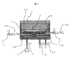
図1は本発明の超臨界レジスト現像装置の構成図である。例えば20MPa、40℃の超臨界二酸化炭素13を充填した超臨界二酸化炭素容器3は、バルブ4を介して36℃に制御された現像室1に接続される。露光後のフッ素系高分子を塗布したレジスト基板5を、現像室1内の基板保持部6に設置後、現像室1を蓋2で密閉する。現像室1に接続されたバルブ4、8、11、12、23を閉じ、高圧二酸化炭素ガス容器10に接続されたバルブ20を開放する。
【0033】
サイフォン式液体二酸化炭素容器9は温度調整器22で25℃に制御することで内部圧力を二酸化炭素の飽和蒸気圧特性から6MPaに設定できる。バルブ8を開放すると、サイフォン式液体二酸化炭素容器9から液体二酸化炭素14が現像室1に導入される。現像室1の圧力がサイフォン式液体二酸化炭素容器9と同じ6MPaとなったらバルブ8を閉じる。現像室1は36℃に制御しているため、導入した液体二酸化炭素は飽和蒸気圧特性から気体となり、6MPa、36℃の気体二酸化炭素で現像室が満たされる。
【0034】
40℃、20MPaの超臨界状態の二酸化炭素13を充填した超臨界二酸化炭素容器3はバルブ4を介して現像室1に接続される。バルブ4を開放すると、超臨界状態の二酸化炭素13が現像室1に導入され、現像室は14MPa、38℃の超臨界二酸化炭素で満たされ、レジスト基板5の現像が始まる。
【0035】
現像室1と超臨界二酸化炭素容器3の圧力が等しくなったらバルブ4を閉じる。このとき、現像室1を満たしている超臨界状態の二酸化炭素がレジストを溶解しても溶解度が変化せずに一定に保つため、バルブ8を開放して高圧ポンプ7で現像室1に毎分50mlの液体二酸化炭素14を圧送する。現像室1に導入された液体二酸化炭素は熱伝導により超臨界状態に変化し、現像室1を満たしている超臨界二酸化炭素と混合する。
【0036】
高圧ポンプ7で液体二酸化炭素の圧送を開始すると同時にバルブ12を開放する。高圧ポンプ7で液体二酸化炭素を圧送することにより現像室1の圧力は昇圧するが、14MPaに設定した背圧制御バルブ33より排出され、現像室1は設定圧力である14MPaに保たれる。200秒間、高圧ポンプ7で液体二酸化炭素の圧送を続けた後、バルブ8を閉じ圧送を停止する。
【0037】
現像を停止するには、現像室1を満たしている二酸化炭素の状態を気体に変化させる。36℃、4MPaの気体二酸化炭素15を充填した高圧二酸化炭素ガス容器10は、バルブ11を介して現像室1に接続される。バルブ11を短時間開放すると、現像室1を満たしている超臨界状態の二酸化炭素が高圧二酸化炭素ガス容器10に排出され、現像室1を満たしていた超臨界二酸化炭素は、6MPa、35℃の気体に状態が変化して現像が停止する。このとき、高圧二酸化炭素ガス容器10は導入される超臨界二酸化炭素のため昇圧するが、4MPaに設定してある背圧制御弁26から排出され4MPaに保たれる。
【0038】
現像を停止したら、現像室1を満たしている二酸化炭素を排出する。バルブ23を開放して圧力制御バルブ24から二酸化炭素を排出する。排出時に現像室1を満たしている二酸化炭素が液化しないように現像室は臨界温度以上の36℃に制御する。
【0039】
現像室1が大気圧になったら現像室蓋2を開けてレジスト基板5を取り出し現像完了となる。
【0040】
図4は超臨界二酸化炭素容器への超臨界二酸化炭素を充填する本発明のレジスト現像装置の構成の一部を示す断面図である。超臨界二酸化炭素容器3は、温度調整器27で20℃に制御する。サイフォン式液体二酸化炭素容器30は図1に示すサイフォン式液体二酸化炭素容器9とは別個に設けられたものであり、温度調整器32で25℃程度に制御される。バルブ4、バルブ18を閉じ、バルブ19を開放すると液体二酸化炭素31が超臨界二酸化炭素容器3に導入される。液体二酸化炭素容器30と超臨界二酸化炭素容器3の圧力が等しくなったら、バルブ18を開放して高圧ポンプ29で液体二酸化炭素31を超臨界二酸化炭素容器3に圧送する。高圧ポンプ29の圧送の開始と同時に温度調整器27で超臨界二酸化炭素容器3を40℃に制御することにより超臨界二酸化炭素容器3内に導入された液体二酸化炭素は超臨界二酸化炭素13へと状態が変化し、圧力は背圧制御バルブ25で20MPaに保たれる。超臨界二酸化炭素容器3内を満たす二酸化炭素が20MPa、40℃になったら充填が完了する。サイフォン式液体二酸化炭素容器30は図1に示すサイフォン式液体二酸化炭素容器9とは別個に設けられるが、サイフォン式液体二酸化炭素容器9の高圧ポンプ7を介して接続させることができる。
【0041】
図5は高圧二酸化炭素ガス容器への高圧二酸化炭素ガスを充填する本発明のレジスト現像装置の構成の一部を示す断面図である。バルブ21を開放すると液体二酸化炭素容器34と高圧二酸化炭素ガス容器10が等圧になるまで気体の二酸化炭素36が導入される。液体二酸化炭素容器34は設定圧力である4MPaを超えて導入される二酸化炭素ガスはバルブ20を開放することにより、背圧制御バルブ26から排出され、4MPaに保たれる。液体二酸化炭素容器34は図1に示す液体二酸化炭素容器9とは別個に設けたものであるが、液体二酸化炭素容器9の気体状態の部分に接続させることができる。
【0042】
図6は液体二酸化炭素容器内への液体二酸化炭素を充填する本発明のレジスト現像装置のレジスト現像中の現像室内部を満たす二酸化炭素の状態を示す模式図である。現像中、液体二酸化炭素導入口39から高圧ポンプ7で液体二酸化炭素14を現像室1に圧送するが、導入直後は液体の状態で現像室底面に貯まる。レジスト基板保持部の形状が、図7に示すように平坦な板状の形状であると、レジスト基板5が液体二酸化炭素38に浸り制御外現像が発生するので、図6に示すように本発明ではレジスト基板5が液体二酸化炭素38に浸らないようにレジスト基板保持部6の形状を椀状としたものである。
【0043】
図3は、このときの現像室内の二酸化炭素の温度状態を示す線図である。現像開始はバルブ4を開放することで始まり、バルブ11を開放することで現像が停止するものであるが、前述のように超臨界二酸化炭素が現像室に導入されて現像を行い、現像の停止に際してはその超臨界二酸化炭素を気体として排出することによって現像室を気体状態にすることによって現像が停止される。即ち、図2に示すように液体状態の二酸化炭素を現像室の加熱によって超臨界二酸化炭素にするにはかなりの時間が必要となるため制御外現像時間が生じるが、本実施例ではこのような時間がほとんど生じないので、その時間を最小化できると共に、現像時間の正確な設定が可能となり最適な現像結果を得ることができる。
【0044】
本実施例によれば、二酸化炭素等の超臨界流体を使用して微細なレジスト現像が、最適なレジスト現像条件の制御で可能になる。特に、現像に用いる超臨界流体の溶解度の時間制御が可能となるので、現像結果のばらつきが無いものを製造できる。
【0045】
又、前述のように、露光後の例えばフッ素系高分子等の二酸化炭素に可溶なレジストを塗布したレジスト基板を超臨界二酸化炭素で現像できると共に、現像処理工程で薬液を使用しないので廃液処理設備が不要となる。
【0046】
更に、本実施例に示すように、現像及びリンス工程で薬液を使用しないので、従来型の乾燥プロセスが不要となり、乾燥時に問題となる微細パターンの倒れを無くすことができ、又、従来の技術では上記の現像処理においては、少なくともその後に洗浄と乾燥の各工程における複数の処理のための装置が必要であるが、本実施例では一つの現像処理装置で現像、洗浄及び乾燥が同時に処理ができるものである。
【0047】
【発明の効果】
本発明によれば、二酸化炭素等の超臨界流体を使用して200mm以上の大口径レジスト基板の微細なレジスト現像が、複数枚数を同時に最適なレジスト現像条件の制御で可能になる。特に、現像に用いる超臨界流体の溶解度の時間制御が可能となり、現像条件を精度良く設定できる。
又、前述のように、露光後の例えばフッ素系高分子等の二酸化炭素に可溶なレジストを塗布したレジスト基板を超臨界二酸化炭素で現像できると共に、現像処理工程で薬液を使用しないので廃液処理設備が不要となる。
更に、本発明によれば、現像及びリンス工程で薬液を使用しないので、従来型の乾燥プロセスが不要となり、乾燥時に問題となる微細パターンの倒れを無くすことができ、又、従来の技術では上記各工程において複数の処理装置が必要であるが、本発明では一つの装置で処理ができる。
【図面の簡単な説明】
【図1】 本発明のレジスト現像装置の構成図である。
【図2】 レジスト現像室内の二酸化炭素の状態変化を示す線図である。
【図3】 図1のレジスト現像室内の二酸化炭素の状態変化を示す線図である。
【図4】 超臨界二酸化炭素容器と液体二酸化炭素容器との接続を示す本発明のレジスト現像装置の構成図である。
【図5】 高圧二酸化炭素容器と液体二酸化炭素容器との接続を示す本発明のレジスト現像装置の構成図である。
【図6】 レジスト現像室内の二酸化炭素の状態を示す本発明のレジスト現像装置の構成図である。
【図7】 レジスト現像室内の二酸化炭素の状態を示す比較のレジスト現像装置の構成図である。
【符号の説明】
1…現像室、2…現像室蓋、3…超臨界二酸化炭素容器、4、11、12、18、19、20、21、23…バルブ、5…レジスト基板、6、40…レジスト基板保持部、7…高圧ポンプ、8…バルブ、9、30、34…サイフォン式液体二酸化炭素容器、10…高圧二酸化炭素ガス容器、13、37…超臨界二酸化炭素、14、31、38…液体二酸化炭素、15、36…高圧二酸化炭素ガス、16、17、22、27、32…温度調整器、24…圧力制御バルブ、25、26、33…背圧制御バルブ、28、35…逆止バルブ、29…高圧ポンプ、39…液体二酸化炭素導入口。[0001]
BACKGROUND OF THE INVENTION
The present invention relates to a novel resist substrate development processing apparatus and method and a surface processing apparatus and method for manufacturing an LSI or the like.
[0002]
[Prior art]
[Patent Document 1]
Japanese Patent Laid-Open No. 7-284739 [Patent Document 2]
Japanese Patent Laid-Open No. 9-139374 [Patent Document 3]
Japanese Patent Laid-Open No. 11-87306 [Patent Document 4]
Japanese Patent Laid-Open No. 1-220828
Conventionally, in order to manufacture a large-scale, high-density, high-performance device, a resist formed on a silicon wafer is exposed, developed, rinsed and dried to form a pattern, and then coated, etched, and rinsed. It was manufactured through a process such as drying. The resist refers to a polymer material that is sensitive to light, X-rays, electron beams, and the like.
In each of these steps, a dedicated processing apparatus is required for each step, and a chemical solution such as a developer and a rinse solution is used in the development and rinse cleaning steps. Therefore, a drying step is essential after the rinse cleaning step.
[0004]
[0005]
[Problems to be solved by the invention]
[Patent Document 1] to [Patent Document 3] show cleaning and drying using a supercritical fluid, but show that a resist substrate having an exposed resist is developed using the supercritical fluid. It has not been.
[0006]
In addition, the inventors of the present application have the problem that pattern collapse occurs due to the action of the surface tension of the chemical solution remaining between the patterns formed on the resist in the drying step, and in order to prevent further pattern collapse, Although a drying method using supercritical carbon dioxide is used as a means of drying process that reduces the surface tension acting between patterns, it is possible to apply drying using supercritical carbon dioxide after alkali development and water rinsing. It was found that it is difficult to use drying by the supercritical fluid because the water cannot be completely discharged during this period and the pattern collapse cannot be suppressed.
[0007]
In the development of a resist substrate having a fine structure using supercritical carbon dioxide described in [Patent Document 4], carbon dioxide introduced into the developing chamber is performed by heating the developing chamber itself, and the heat capacity thereof is When the temperature is increased, during the temperature rise to the set temperature that is higher than the critical temperature, there is a problem in that sufficient results cannot be obtained because the time for which solubility is out of control becomes longer for the target solubility = development conditions. Particularly, in order to develop a plurality of large-diameter resist substrates having a size of 200 mm or more, when the liquid carbon dioxide is introduced, a part of the resist substrate comes into contact with the liquid carbon dioxide, and uncontrolled development occurs. It has been found that there is a problem that causes variation.
[0008]
An object of the present invention is to provide a resist development process capable of performing fine resist development in a short time, with little variation, and high accuracy using a supercritical fluid such as carbon dioxide which does not require a waste liquid treatment facility without using a chemical solution. apparatus and to provide its way.
[0009]
[Means for Solving the Problems]
The inventors of the present application use the supercritical carbon dioxide to prevent pattern collapse in the above process, and without using a liquid such as a developing solution or a rinsing solution, the resist substrate after exposure with the supercritical fluid is used. The present inventors have found an apparatus and a method for rapidly developing. In development, the resist can be removed from either the exposed part or the unexposed part.
[0010]
The solubility of the solvent in the solute depends on the temperature and density of the solvent. When a certain solvent is used for the purpose of developing a resist, under a condition for obtaining a solubility suitable for the development processing of the resist substrate, the solvent as a developer exceeds a critical point, that is, a state called a supercritical state. It may become. Supercritical fluid can change density by controlling pressure and temperature, and can selectively obtain solubility.
[0011]
In addition, the supercritical fluid has the same diffusivity as gas, and can change the state without passing through the equilibrium line from liquid to gas. That is, the state can be changed to gas by controlling the pressure of the fluid below the critical pressure while keeping the temperature of the fluid above the critical temperature. This state change does not cause surface tension to act.
[0012]
As a solvent for developing a device with a fine structure such as a resist substrate using a supercritical fluid, a substance such as carbon dioxide, which becomes a gas at normal temperature and atmospheric pressure and has a relatively low critical pressure and critical temperature, is suitable. ing. Carbon dioxide has a critical temperature of 31 ° C. and a critical pressure of 7.3 MPa. As a resist material when carbon dioxide is used as a developing solvent, for example, a fluorine-based polymer resist that is soluble in liquid or supercritical carbon dioxide is suitable.
[0013]
When the state of carbon dioxide as the developing solvent is a gas, the solubility is extremely small because the density is low with respect to the liquid and the supercritical state. Only when carbon dioxide as a developing solvent is in a supercritical state or in a liquid state, a resist developing effect can be obtained.
[0014]
That is, resist development is performed when the development processing chamber in which the resist substrate is installed is filled with liquid or supercritical carbon dioxide, and the resist does not dissolve when the state of carbon dioxide filling the development chamber is changed to gas. Resist development stops. That is, the time during which the developing chamber is filled with liquid or supercritical carbon dioxide is the resist developing time.
[0015]
For resist development using supercritical carbon dioxide, for example, after exposing a resist substrate coated with a carbon dioxide-soluble resist such as a fluoropolymer to the development chamber, the development chamber is filled with supercritical carbon dioxide. This is done by utilizing the solubility of supercritical carbon dioxide in fluorine-based polymers.
[0016]
The development is stopped by discharging supercritical carbon dioxide in the developing chamber, lowering the pressure in the developing chamber, and changing the carbon dioxide state to gas. Further, when the carbon dioxide in the developing chamber is discharged and the atmospheric pressure is reached, the resist substrate is taken out of the developing chamber and the developing process is completed.
[0017]
The solubility of carbon dioxide in a fluorine-based polymer is about hexane. In particular, a large amount of supercritical carbon dioxide is required to develop a plurality of large-diameter resist substrates of 200 mm or more. The high-pressure container serving as the developing chamber is required to have a volume filled with supercritical carbon dioxide necessary for development, and accordingly, the developing chamber becomes larger and the heat capacity increases.
[0018]
Carbon dioxide as the developing solvent is introduced from the siphon-type liquid carbon dioxide container into the developing chamber as a liquid, and then the developing chamber is controlled to a set temperature higher than the critical temperature to change the carbon dioxide state from liquid to supercritical. Change. As the temperature rises, the pressure in the developing chamber is also increased. The pressure in the developing chamber is maintained at a set pressure that is higher than the critical pressure by a back pressure control valve.
[0019]
As for the introduction of carbon dioxide from the siphon type liquid carbon dioxide container into the developing chamber, the liquid carbon dioxide is introduced into the developing chamber until both pressures become equal. At this time, if the ratio of the liquid carbon dioxide filling the developing chamber is not at least 50% or more of the volume of the developing chamber, even if the temperature of the developing chamber is raised to a critical temperature or higher, the supercritical state is not achieved.
[0020]
Since the ratio of liquid carbon dioxide in the developing chamber depends on the saturated vapor pressure characteristics of carbon dioxide, the internal pressure becomes 6 MPa or more when the temperature of the siphon type carbon dioxide container is controlled to 25 ° C. or higher, and the temperature of the developing chamber Is controlled to about 20 ° C., the ratio of liquid carbon dioxide filling the developing chamber becomes about 80%. In this state, if the temperature of the developing chamber is raised to about 35 ° C., it is filled with supercritical carbon dioxide of about 10 MPa.
[0021]
From the above, when introducing liquid carbon dioxide into the developing chamber, it is necessary to control the developing chamber at about 20 ° C. Therefore, in order to raise the temperature of the developing chamber having a capacity for developing a plurality of large-sized resist substrates of 200 mm or more to a critical temperature or more, a large amount of heat supply is required, and a long time is required as shown in FIG. become. The control time from the introduction of liquid carbon dioxide to the set temperature can be simply calculated from the heat capacity of the high-pressure vessel, the capacity of the heater, and the heat transfer efficiency, but the smaller the heat capacity of the developing chamber, the carbon dioxide that fills the developing chamber. Although it is clear that the time required for temperature control to change the state of the liquid from the liquid to the supercritical state can be reduced, the heat capacity of the developing chamber is increased, and further, for developing a plurality of large-diameter resist substrates of 200 mm or more. Is solved by the following apparatus and method.
[0022]
The present invention includes a developing chamber and develops the exposed resist houses a resist substrate having a resist after exposure on the substrate by a developing solvent consisting of a supercritical fluid, the greater connected via a valve to the developing chamber supercritical fluid container for storing the critical fluid, a high pressure gas container for storing a high pressure gas of the developing solvent which is connected via a valve before Symbol developing chamber, by a high pressure connected via a valve to the developing chamber The supercritical fluid in the developing chamber is changed to gas without being liquefied by opening a liquid container that stores the liquefied liquid of the developing solvent and the valve connected between the developing chamber and the high-pressure gas container. A back pressure control valve provided in the high-pressure gas container; and the developing chamber for discharging the supercritical fluid in the developing chamber to the high-pressure gas container without liquefying while maintaining the temperature above the critical temperature. And the resist substrate provided in the developing chamber for preventing the liquid developing solvent from coming into contact with the resist substrate when the developing solvent in the liquid state is introduced into the developing chamber. And a holding means for holding the resist development processing apparatus .
[0023]
That is, a supercritical fluid is directly introduced into a developing chamber in which a resist substrate after exposure is installed, and is used in a resist development processing apparatus that utilizes the dissolution characteristics of the introduced fluid, and is connected to the developing chamber via a valve. The developing container is filled with a supercritical fluid having a set density and temperature by filling the fluid container with the supercritical fluid and opening the valve. A high-pressure container piped in the developing chamber through a valve is filled with a gaseous developing solvent at a high pressure, and the valve is opened to convert the supercritical fluid filling the developing chamber into a gas without liquefying it. The gas is liquefied by having a back pressure control valve that changes the state, and by discharging while controlling the temperature of the gas in the resist development processing chamber above the critical point when discharging the high-pressure gas filling the resist development processing chamber. A temperature regulator that exhausts the resist development chamber without causing the liquid development solvent to come into contact with the resist substrate when the liquid serving as the development solvent is introduced into the development chamber or when the pressure in the resist development chamber is increased. Holding means for preventing, equipped with a high-pressure pump for pumping a liquid developing solvent into the resist drying chamber, from each container supplied to the developing chamber Preferably it has a temperature regulator for smaller adjust the temperature difference between the serial developing solvent. By pumping the developing solvent to the developing chamber with a high-pressure pump, the volume and heat capacity of the developing chamber can be minimized.
[0026]
More specifically, in a resist development processing method in which development is performed by introducing a developing solvent composed of a supercritical fluid into a developing chamber that houses a resist substrate having a resist after exposure on the substrate.
Filling the developing chamber with a liquid of the developing solvent so as not to contact the resist substrate;
Introducing the supercritical fluid into the developing chamber with the supercritical fluid;
A step of pumping the liquid developing solvent into the developing chamber;
And a step of discharging the supercritical fluid without liquefying while maintaining the temperature in the developing chamber at or above the critical temperature.
[0027]
Furthermore, the present invention relates to a resist development processing method in which development is performed by introducing a development solvent composed of a supercritical fluid into a development chamber containing a resist substrate having a resist after exposure on the substrate.
A step of storing the resist substrate after the exposure to the developing chamber,
A step of liquid carbon dioxide is introduced so as not to contact the resist substrate in the developing chamber,
And performing pre-Symbol developing introducing supercritical carbon dioxide into the developing chamber,
Pumping liquid carbon dioxide into the developing chamber and mixing with the supercritical carbon dioxide;
A step of stopping the development said supercritical carbon dioxide in the developing chamber is discharged into high-pressure carbon dioxide gas container pressurized carbon dioxide gas is filled the supercritical carbon dioxide in the developing chamber is changed to a gaseous state,
In the resist developing method characterized by sequentially and a step of discharging in a gaseous state without liquefying the supercritical carbon dioxide while maintaining above the critical temperature the temperature in said developing chamber.
[0028]
In the method of the present invention, the temperature of the developing solvent supplied to the developing chamber is adjusted so that the temperature change of the resist substrate in the developing chamber is within 10 ° C., more preferably within 5 ° C.
[0031]
The resist developing apparatus and method using the supercritical fluid of the present invention, and the solubility of the supercritical fluid as a developing solvent during resist development can be accurately controlled. As a result, a resist pattern that requires high-performance characteristics can be developed without variation, particularly in the formation of a fine pattern with a resist width of 100 nm to 20 nm in the future. Alternatively, the surface treatment apparatus and its method can perform rapid processing in washing and drying separately from the above-described development, and can cope with the formation of fine patterns.
[0032]
DETAILED DESCRIPTION OF THE INVENTION
FIG. 1 is a block diagram of a supercritical resist developing apparatus according to the present invention. For example, a supercritical
[0033]
The siphon type liquid
[0034]
A supercritical
[0035]
When the pressures in the developing
[0036]
The valve 12 is opened simultaneously with the start of the pumping of liquid carbon dioxide by the high-pressure pump 7. The pressure of the developing
[0037]
To stop development, the state of carbon dioxide filling the developing
[0038]
When the development is stopped, the carbon dioxide filling the developing
[0039]
When the developing
[0040]
FIG. 4 is a cross-sectional view showing a part of the configuration of the resist developing apparatus of the present invention for filling a supercritical carbon dioxide container with supercritical carbon dioxide. The supercritical
[0041]
FIG. 5 is a cross-sectional view showing a part of the configuration of the resist developing apparatus of the present invention for filling high pressure carbon dioxide gas into a high pressure carbon dioxide gas container. When the valve 21 is opened, gaseous carbon dioxide 36 is introduced until the liquid
[0042]
FIG. 6 is a schematic view showing a state of carbon dioxide filling the inside of the developing chamber during resist development of the resist developing apparatus of the present invention in which liquid carbon dioxide is filled into the liquid carbon dioxide container. During the development, the liquid carbon dioxide 14 is pumped from the liquid carbon dioxide inlet 39 to the developing
[0043]
FIG. 3 is a diagram showing the temperature state of carbon dioxide in the developing chamber at this time. Development starts when the
[0044]
According to the present embodiment, fine resist development using a supercritical fluid such as carbon dioxide becomes possible by controlling optimum resist development conditions. In particular, since it is possible to control the solubility of the supercritical fluid used for development, it is possible to produce a product with no variation in development results.
[0045]
In addition, as described above, a resist substrate coated with a carbon dioxide-soluble resist such as a fluorine-based polymer after exposure can be developed with supercritical carbon dioxide, and since no chemical solution is used in the development process, waste liquid treatment is performed. Equipment is not required.
[0046]
Furthermore, as shown in the present embodiment, since no chemical solution is used in the development and rinsing steps, the conventional drying process is unnecessary, and the collapse of the fine pattern that becomes a problem during drying can be eliminated. In the above development processing, at least a device for a plurality of processing in each step of washing and drying is required after that, but in this embodiment, development, washing and drying are simultaneously performed in one development processing device. It can be done.
[0047]
【The invention's effect】
According to the present invention, fine resist development of a large-diameter resist substrate having a diameter of 200 mm or more using a supercritical fluid such as carbon dioxide can be performed by controlling optimal resist development conditions for a plurality of sheets simultaneously. In particular, the time control of the solubility of the supercritical fluid used for development becomes possible, and development conditions can be set with high accuracy.
In addition, as described above, a resist substrate coated with a carbon dioxide-soluble resist such as a fluorine-based polymer after exposure can be developed with supercritical carbon dioxide, and since no chemical solution is used in the development process, waste liquid treatment is performed. Equipment is not required.
Furthermore, according to the present invention, since no chemical solution is used in the development and rinsing steps, a conventional drying process is not necessary, and the collapse of a fine pattern that becomes a problem during drying can be eliminated. In each step, a plurality of processing apparatuses are required, but in the present invention, processing can be performed with one apparatus.
[Brief description of the drawings]
FIG. 1 is a configuration diagram of a resist developing apparatus of the present invention.
FIG. 2 is a diagram showing a change in the state of carbon dioxide in a resist developing chamber.
3 is a diagram showing a change in the state of carbon dioxide in the resist developing chamber of FIG. 1. FIG.
FIG. 4 is a configuration diagram of a resist developing apparatus of the present invention showing connection between a supercritical carbon dioxide container and a liquid carbon dioxide container.
FIG. 5 is a configuration diagram of the resist developing apparatus of the present invention showing connection between a high-pressure carbon dioxide container and a liquid carbon dioxide container.
FIG. 6 is a configuration diagram of the resist developing apparatus of the present invention showing the state of carbon dioxide in the resist developing chamber.
FIG. 7 is a configuration diagram of a comparative resist developing apparatus showing a state of carbon dioxide in the resist developing chamber.
[Explanation of symbols]
DESCRIPTION OF
Claims (7)
前記露光後のレジスト基板を前記現像室に収納する工程と、
前記現像室に前記現像溶媒の液体を前記レジスト基板に接触しないように充填する工程と、
前記現像室に前記超臨界流体を導入する工程と、
前記現像室に前記液体状態の現像溶媒を圧送する工程と、
前記現像室内の温度を臨界温度以上に維持しながら前記超臨界流体を液化させずに排出させる工程と、
を順次有することを特徴とするレジスト現像処理方法。In a resist development processing method of developing by introducing a developing solvent composed of a supercritical fluid into a developing chamber containing a resist substrate having a resist after exposure on the substrate,
Storing the resist substrate after the exposure in the developing chamber;
Filling the developing chamber with a liquid of the developing solvent so as not to contact the resist substrate;
Introducing the supercritical fluid into the developing chamber;
A step of pumping the liquid developing solvent into the developing chamber;
Discharging the supercritical fluid without liquefying while maintaining the temperature in the developing chamber at or above the critical temperature;
The resist development processing method characterized by having sequentially.
前記露光後のレジスト基板を前記現像室に収納する工程と、
前記現像室に液体二酸化炭素が前記レジスト基板に接触しないように充填する工程と、
前記現像室に前記超臨界二酸化炭素を導入し前記現像を行う工程と、
前記現像室に液体二酸化炭素を圧送し前記超臨界二酸化炭素と混合する工程と、
前記現像室の超臨界二酸化炭素を高圧二酸化炭素ガスが充填された高圧二酸化炭素ガス容器に排出し前記現像室内の前記超臨界二酸化炭素を気体状態に変化させ前記現像を停止する工程と、
前記現像室内の温度を臨界温度以上に維持しながら前記超臨界二酸化炭素を液化させずに気体状態で排出する工程と、
を順次有することを特徴とするレジスト現像処理方法。In a resist development processing method for developing by introducing supercritical carbon dioxide into a developing chamber containing a resist substrate having a resist after exposure on the substrate,
Storing the resist substrate after the exposure in the developing chamber;
Filling the developing chamber with liquid carbon dioxide so as not to contact the resist substrate;
Introducing the supercritical carbon dioxide into the developing chamber and performing the development;
Pumping liquid carbon dioxide into the developing chamber and mixing with the supercritical carbon dioxide;
Discharging the supercritical carbon dioxide in the developing chamber into a high-pressure carbon dioxide gas container filled with high-pressure carbon dioxide gas, changing the supercritical carbon dioxide in the developing chamber into a gaseous state, and stopping the development;
Discharging the supercritical carbon dioxide in a gaseous state without liquefying while maintaining the temperature in the developing chamber above the critical temperature;
The resist development processing method characterized by having sequentially.
Priority Applications (3)
| Application Number | Priority Date | Filing Date | Title |
|---|---|---|---|
| JP2002334781A JP3861798B2 (en) | 2002-11-19 | 2002-11-19 | Resist development processing apparatus and method |
| US10/705,845 US7033089B2 (en) | 2002-11-19 | 2003-11-13 | Method of developing a resist film and a resist development processor |
| US11/359,483 US7179000B2 (en) | 2002-11-19 | 2006-02-23 | Method of developing a resist film and a resist development processor |
Applications Claiming Priority (1)
| Application Number | Priority Date | Filing Date | Title |
|---|---|---|---|
| JP2002334781A JP3861798B2 (en) | 2002-11-19 | 2002-11-19 | Resist development processing apparatus and method |
Publications (2)
| Publication Number | Publication Date |
|---|---|
| JP2004172261A JP2004172261A (en) | 2004-06-17 |
| JP3861798B2 true JP3861798B2 (en) | 2006-12-20 |
Family
ID=32290328
Family Applications (1)
| Application Number | Title | Priority Date | Filing Date |
|---|---|---|---|
| JP2002334781A Expired - Fee Related JP3861798B2 (en) | 2002-11-19 | 2002-11-19 | Resist development processing apparatus and method |
Country Status (2)
| Country | Link |
|---|---|
| US (2) | US7033089B2 (en) |
| JP (1) | JP3861798B2 (en) |
Families Citing this family (9)
| Publication number | Priority date | Publication date | Assignee | Title |
|---|---|---|---|---|
| US20050227183A1 (en) * | 2002-01-11 | 2005-10-13 | Mark Wagner | Compositions and methods for image development of conventional chemically amplified photoresists |
| JP3861798B2 (en) * | 2002-11-19 | 2006-12-20 | 株式会社日立ハイテクサイエンスシステムズ | Resist development processing apparatus and method |
| WO2006081534A1 (en) * | 2005-01-28 | 2006-08-03 | Micell Technologies, Inc. | Compositions and methods for image development of conventional chemically amplified photoresists |
| US7410751B2 (en) * | 2005-01-28 | 2008-08-12 | Micell Technologies, Inc. | Compositions and methods for image development of conventional chemically amplified photoresists |
| US20070269749A1 (en) * | 2006-05-18 | 2007-11-22 | Richard Elliot Schenker | Methods to reduce the minimum pitch in a pattern |
| KR100889307B1 (en) * | 2007-08-14 | 2009-03-18 | 세메스 주식회사 | Process chamber and substrate processing equipment having the same, and substrate processing method of the equipment |
| US10698313B2 (en) | 2017-11-22 | 2020-06-30 | Taiwan Semiconductor Manufacturing Co., Ltd. | Apparatus and method for developing a photoresist coated substrate |
| CN110308624B (en) * | 2019-05-17 | 2020-10-30 | 华中科技大学 | A kind of laser lithography three-dimensional micro-nano device supercritical fluid developing device and method |
| KR20230001735A (en) | 2021-06-29 | 2023-01-05 | 세메스 주식회사 | Substrate processing apparatus and substrate processing method |
Family Cites Families (15)
| Publication number | Priority date | Publication date | Assignee | Title |
|---|---|---|---|---|
| JP2663483B2 (en) * | 1988-02-29 | 1997-10-15 | 勝 西川 | Method of forming resist pattern |
| JPH0235458A (en) | 1988-07-26 | 1990-02-06 | Matsushita Electric Ind Co Ltd | Pattern forming method |
| US5185296A (en) * | 1988-07-26 | 1993-02-09 | Matsushita Electric Industrial Co., Ltd. | Method for forming a dielectric thin film or its pattern of high accuracy on a substrate |
| JP3017637B2 (en) | 1994-04-15 | 2000-03-13 | シャープ株式会社 | Cleaning equipment |
| JPH09139374A (en) | 1995-11-15 | 1997-05-27 | Hitachi Ltd | Surface treatment method and apparatus and element obtained thereby |
| JPH1187306A (en) | 1997-09-12 | 1999-03-30 | Nippon Telegr & Teleph Corp <Ntt> | Supercritical drying equipment |
| JP3492528B2 (en) | 1998-09-09 | 2004-02-03 | 日本電信電話株式会社 | Supercritical drying apparatus and method |
| US6358673B1 (en) * | 1998-09-09 | 2002-03-19 | Nippon Telegraph And Telephone Corporation | Pattern formation method and apparatus |
| AU4902201A (en) * | 1999-11-02 | 2001-07-03 | Tokyo Electron Limited | Method and apparatus for supercritical processing of a workpiece |
| US6286231B1 (en) * | 2000-01-12 | 2001-09-11 | Semitool, Inc. | Method and apparatus for high-pressure wafer processing and drying |
| JP2003122024A (en) | 2001-10-19 | 2003-04-25 | Matsushita Electric Ind Co Ltd | Pattern forming method |
| US6924086B1 (en) * | 2002-02-15 | 2005-08-02 | Tokyo Electron Limited | Developing photoresist with supercritical fluid and developer |
| JP4133209B2 (en) * | 2002-10-22 | 2008-08-13 | 株式会社神戸製鋼所 | High pressure processing equipment |
| JP3861798B2 (en) * | 2002-11-19 | 2006-12-20 | 株式会社日立ハイテクサイエンスシステムズ | Resist development processing apparatus and method |
| US20040198066A1 (en) * | 2003-03-21 | 2004-10-07 | Applied Materials, Inc. | Using supercritical fluids and/or dense fluids in semiconductor applications |
-
2002
- 2002-11-19 JP JP2002334781A patent/JP3861798B2/en not_active Expired - Fee Related
-
2003
- 2003-11-13 US US10/705,845 patent/US7033089B2/en not_active Expired - Fee Related
-
2006
- 2006-02-23 US US11/359,483 patent/US7179000B2/en not_active Expired - Fee Related
Also Published As
| Publication number | Publication date |
|---|---|
| JP2004172261A (en) | 2004-06-17 |
| US20060140624A1 (en) | 2006-06-29 |
| US7033089B2 (en) | 2006-04-25 |
| US7179000B2 (en) | 2007-02-20 |
| US20040096210A1 (en) | 2004-05-20 |
Similar Documents
| Publication | Publication Date | Title |
|---|---|---|
| US6286231B1 (en) | Method and apparatus for high-pressure wafer processing and drying | |
| JP3965693B2 (en) | Fine structure drying method and apparatus and high-pressure vessel thereof | |
| US7179000B2 (en) | Method of developing a resist film and a resist development processor | |
| US8709170B2 (en) | Supercritical drying method for semiconductor substrate | |
| JP2004311507A (en) | Method, device, and system for drying microstructure | |
| JP3494939B2 (en) | Supercritical drying method and apparatus | |
| JP3782366B2 (en) | Supercritical processing method and supercritical processing apparatus | |
| JP3492528B2 (en) | Supercritical drying apparatus and method | |
| JP4546314B2 (en) | Fine structure drying method and apparatus | |
| KR20190002060A (en) | Apparatus and Method for processing substrate | |
| JP4247087B2 (en) | Fine structure drying method and apparatus | |
| JPH1192990A (en) | Plating pretreatment | |
| TW511187B (en) | Etching method, processing apparatus and etching apparatus | |
| JP4372590B2 (en) | Fine structure drying method and apparatus | |
| JP3914134B2 (en) | Supercritical drying method and apparatus | |
| JP3553904B2 (en) | Supercritical drying method | |
| JP2005081302A (en) | Washing method and washing device of electronic component members by supercritical fluid | |
| JP4342896B2 (en) | Fine structure drying method and apparatus | |
| JP2000223467A (en) | Supercritical drying method and system | |
| JP2006332215A (en) | Fine structure processing method and apparatus | |
| JP2005286105A (en) | Fine structure drying method and apparatus thereof | |
| JP4230830B2 (en) | Supercritical processing equipment | |
| JP3888281B2 (en) | Fine structure drying apparatus and drying method thereof | |
| JP2004363440A (en) | Method and device for supercritical drying | |
| TW202439394A (en) | Substrate processing apparatus |
Legal Events
| Date | Code | Title | Description |
|---|---|---|---|
| A621 | Written request for application examination |
Free format text: JAPANESE INTERMEDIATE CODE: A621 Effective date: 20041004 |
|
| A977 | Report on retrieval |
Free format text: JAPANESE INTERMEDIATE CODE: A971007 Effective date: 20060410 |
|
| A131 | Notification of reasons for refusal |
Free format text: JAPANESE INTERMEDIATE CODE: A131 Effective date: 20060418 |
|
| A521 | Request for written amendment filed |
Free format text: JAPANESE INTERMEDIATE CODE: A523 Effective date: 20060619 |
|
| TRDD | Decision of grant or rejection written | ||
| A01 | Written decision to grant a patent or to grant a registration (utility model) |
Free format text: JAPANESE INTERMEDIATE CODE: A01 Effective date: 20060905 |
|
| A61 | First payment of annual fees (during grant procedure) |
Free format text: JAPANESE INTERMEDIATE CODE: A61 Effective date: 20060918 |
|
| R150 | Certificate of patent or registration of utility model |
Free format text: JAPANESE INTERMEDIATE CODE: R150 |
|
| LAPS | Cancellation because of no payment of annual fees |