JP3859112B2 - Image forming apparatus - Google Patents
Image forming apparatus Download PDFInfo
- Publication number
- JP3859112B2 JP3859112B2 JP2000050741A JP2000050741A JP3859112B2 JP 3859112 B2 JP3859112 B2 JP 3859112B2 JP 2000050741 A JP2000050741 A JP 2000050741A JP 2000050741 A JP2000050741 A JP 2000050741A JP 3859112 B2 JP3859112 B2 JP 3859112B2
- Authority
- JP
- Japan
- Prior art keywords
- toner
- intermediate transfer
- cleaning
- image
- transfer
- Prior art date
- Legal status (The legal status is an assumption and is not a legal conclusion. Google has not performed a legal analysis and makes no representation as to the accuracy of the status listed.)
- Expired - Fee Related
Links
- 238000004140 cleaning Methods 0.000 claims description 289
- 230000005684 electric field Effects 0.000 claims description 26
- 239000002245 particle Substances 0.000 claims description 7
- 230000003746 surface roughness Effects 0.000 claims description 7
- 238000007790 scraping Methods 0.000 claims description 3
- 238000010079 rubber tapping Methods 0.000 claims 1
- 108091008695 photoreceptors Proteins 0.000 description 15
- 230000000694 effects Effects 0.000 description 7
- 206010047571 Visual impairment Diseases 0.000 description 4
- 239000011347 resin Substances 0.000 description 4
- 229920005989 resin Polymers 0.000 description 4
- 238000011144 upstream manufacturing Methods 0.000 description 3
- 239000003086 colorant Substances 0.000 description 2
- 230000002093 peripheral effect Effects 0.000 description 2
- 229910001220 stainless steel Inorganic materials 0.000 description 2
- 239000010935 stainless steel Substances 0.000 description 2
- 239000002344 surface layer Substances 0.000 description 2
- 229920002943 EPDM rubber Polymers 0.000 description 1
- YCKRFDGAMUMZLT-UHFFFAOYSA-N Fluorine atom Chemical compound [F] YCKRFDGAMUMZLT-UHFFFAOYSA-N 0.000 description 1
- 230000002159 abnormal effect Effects 0.000 description 1
- 230000007423 decrease Effects 0.000 description 1
- 239000004744 fabric Substances 0.000 description 1
- 229910052731 fluorine Inorganic materials 0.000 description 1
- 239000011737 fluorine Substances 0.000 description 1
- 239000006260 foam Substances 0.000 description 1
- 239000010410 layer Substances 0.000 description 1
- 239000002184 metal Substances 0.000 description 1
- 229910052751 metal Inorganic materials 0.000 description 1
- 229920000728 polyester Polymers 0.000 description 1
- 229920002635 polyurethane Polymers 0.000 description 1
- 239000004814 polyurethane Substances 0.000 description 1
- 238000011084 recovery Methods 0.000 description 1
- 230000000007 visual effect Effects 0.000 description 1
- 239000002699 waste material Substances 0.000 description 1
Images


Classifications
-
- G—PHYSICS
- G03—PHOTOGRAPHY; CINEMATOGRAPHY; ANALOGOUS TECHNIQUES USING WAVES OTHER THAN OPTICAL WAVES; ELECTROGRAPHY; HOLOGRAPHY
- G03G—ELECTROGRAPHY; ELECTROPHOTOGRAPHY; MAGNETOGRAPHY
- G03G15/00—Apparatus for electrographic processes using a charge pattern
- G03G15/14—Apparatus for electrographic processes using a charge pattern for transferring a pattern to a second base
- G03G15/16—Apparatus for electrographic processes using a charge pattern for transferring a pattern to a second base of a toner pattern, e.g. a powder pattern, e.g. magnetic transfer
- G03G15/1605—Apparatus for electrographic processes using a charge pattern for transferring a pattern to a second base of a toner pattern, e.g. a powder pattern, e.g. magnetic transfer using at least one intermediate support
- G03G15/161—Apparatus for electrographic processes using a charge pattern for transferring a pattern to a second base of a toner pattern, e.g. a powder pattern, e.g. magnetic transfer using at least one intermediate support with means for handling the intermediate support, e.g. heating, cleaning, coating with a transfer agent
-
- G—PHYSICS
- G03—PHOTOGRAPHY; CINEMATOGRAPHY; ANALOGOUS TECHNIQUES USING WAVES OTHER THAN OPTICAL WAVES; ELECTROGRAPHY; HOLOGRAPHY
- G03G—ELECTROGRAPHY; ELECTROPHOTOGRAPHY; MAGNETOGRAPHY
- G03G2215/00—Apparatus for electrophotographic processes
- G03G2215/01—Apparatus for electrophotographic processes for producing multicoloured copies
- G03G2215/0167—Apparatus for electrophotographic processes for producing multicoloured copies single electrographic recording member
- G03G2215/0174—Apparatus for electrophotographic processes for producing multicoloured copies single electrographic recording member plural rotations of recording member to produce multicoloured copy
-
- G—PHYSICS
- G03—PHOTOGRAPHY; CINEMATOGRAPHY; ANALOGOUS TECHNIQUES USING WAVES OTHER THAN OPTICAL WAVES; ELECTROGRAPHY; HOLOGRAPHY
- G03G—ELECTROGRAPHY; ELECTROPHOTOGRAPHY; MAGNETOGRAPHY
- G03G2215/00—Apparatus for electrophotographic processes
- G03G2215/16—Transferring device, details
- G03G2215/1647—Cleaning of transfer member
- G03G2215/1661—Cleaning of transfer member of transfer belt
Landscapes
- Physics & Mathematics (AREA)
- General Physics & Mathematics (AREA)
- Electrostatic Charge, Transfer And Separation In Electrography (AREA)
- Cleaning In Electrography (AREA)
Description
【0001】
【発明の属する技術分野】
本発明は、表面が移動するように駆動されながら静電潜像が形成される像担持体と、該静電潜像を正規極性に帯電したトナーによってトナー像として可視像化する現像装置と、表面が移動するように駆動される中間転写体と、正規極性に帯電したトナーが前記像担持体から中間転写体に転移する向きの電界を形成して、像担持体上のトナー像を中間転写体上に1次転写する1次転写手段と、トナー像を中間転写体に1次転写したあとの像担持体表面に存在する転写残トナーを除去する第1のクリーニング装置と、正規極性に帯電したトナーが中間転写体から記録媒体上に転移する向きの電界を形成して、中間転写体上のトナー像を記録媒体上に2次転写する2次転写手段と、トナー像を記録媒体に2次転写したあとの中間転写体表面に存在する転写残トナーを除去する第2のクリーニング装置とを具備し、該第2のクリーニング装置は、中間転写体表面に対置され、かつ前記正規極性と逆の極性の電圧を印加されるクリーニング部材と、中間転写体表面から該クリーニング部材に転移したトナーを除去する清掃手段とを有している画像形成装置に関する。
【0002】
【従来の技術】
電子複写機、プリンタ、ファクシミリ或いはこれらの少なくとも2つの機能を備えた複合機などとして構成される上記形式の画像形成装置は従来より公知である。この形式の画像形成装置は、その中間転写体上に互いに色の異なるトナー像を重ねて1次転写し、その重ね合せトナー像を記録媒体上に一括して2次転写することにより、カラー画像を形成することができる。
【0003】
トナー像を記録媒体上に2次転写した後の中間転写体上に存在する転写残トナーは、第2のクリーニング装置により、その中間転写体表面から除去される。また、第2のクリーニング装置は、2次転写手段の作用を受けない中間転写体上のトナーを除去する働きもなす。例えば、画像形成動作中に記録媒体が搬送トラブル(ジャム)を起こしたとき、画像形成装置の動作が止められ、そのトラブルを起こした記録媒体の除去後、すなわちジャム処理後に、画像形成動作が再開されるが、その再開時に、2次転写領域よりも中間転写体移動方向上流側の中間転写体上に形成されているトナー像は、2次転写作用を受けることなく2次転写領域を通過し、第2のクリーニング装置でそのトナーが中間転写体表面から除去される。このように、第2のクリーニング装置は、中間転写体上の転写残トナーだけでなく、2次転写作用を受けない中間転写体上のトナーをも除去するものであるが、これらのトナーの除去効率、すなわちそのクリーニング効率が低下すれば、中間転写体上に残されたトナーが、次の記録媒体上に付着し、その記録媒体上のトナー像の画質を劣化させたり、地肌汚れが著しくなる欠点を免れない。
【0004】
そこで、従来の画像形成装置においては、第2のクリーニング装置のクリーニング部材によって、中間転写体上の転写残トナーと、2次転写作用を受けない中間転写体上のトナーを最も効率よく除去できるように、すなわちクリーニング部材によるクリーニング効率が最大となるように、クリーニング部材に対して印加する電圧の値を設定していた。
【0005】
ところが、本発明者の検討したところによると、クリーニング部材への印加電圧の値を上述のように設定すると、第2のクリーニング装置によって取り切れなかった中間転写体上のわずかなトナーが次の記録媒体上に転移しやすくなり、かえって次の記録媒体に地肌汚れが発生し、当該記録媒体上に2次転写されたトナー像の画質を劣化させる不具合のあることが判明した。
【0006】
トナー像の2次転写が行われる2次転写領域よりも中間転写体表面の移動方向下流側に帯電器を設け、その帯電器によって中間転写体上の転写残トナーをその正規極性と逆の極性に強制的に帯電させ、その転写残トナーを、トナー像の1次転写の行われる1次転写領域において像担持体表面の側に静電的に移行させ、その移行したトナーを像担持体清掃用のクリーニング装置によって像担持体表面から除去する画像形成装置が提案されている。この画像形成装置は、中間転写体上の転写残トナーを、中間転写体用のクリーニング装置によって除去することをやめ、その転写残トナーを全て像担持体表面に戻し、像担持体用のクリーニング装置によってそのトナーを像担持体から除去するものである。かかる構成によれば、2次転写後に中間転写体上に付着する転写残トナーについては、その量が少ないため、これを像担持体に転移させて当該トナーを像担持体用のクリーニング装置によって効率よく除去することが可能である。
【0007】
ところが、上記提案に係る画像形成装置によっては、2次転写手段による2次転写作用を受けなかった中間転写体上のトナーを除去することは困難である。すなわち、前述のようにジャム処理後に画像形成動作を再開したとき、中間転写体上に存在するトナーの量は、2次転写後の中間転写体上の転写残トナーに比べてはるかに多量であり、しかも、そのトナーは2次転写作用を受けないので、正規極性に強く帯電している。従来の提案に係る画像形成装置においては、このように正規極性に帯電した多量のトナーについても、これを帯電器によって正規極性と逆の極性に強制的に帯電させ、これを像担持体表面に静電的に戻すのであるが、正規極性に強く帯電した多量のトナーの全てを、帯電器によって正規極性と逆極性に帯電させることは困難である。このため、像担持体表面に転移しない多量のトナーが中間転写体上に残され、これが次の記録媒体上に転移し、その記録媒体がトナーで汚されるおそれがある。
【0008】
【発明が解決しようとする課題】
本発明は、上述した新規な認識に基づきなされたものであり、その目的とするところは、クリーニングされずに中間転写体上に残されたトナーが記録媒体に転移するトナーの量を従来よりも効果的に減少させることのできる冒頭に記載した形式の画像形成装置を提案することにある。
【0009】
【課題を解決するための手段】
本発明は、上記目的を達成するため、冒頭に記載した形式の画像形成装置において、前記クリーニング部材に印加する電圧の絶対値を、前記2次転写手段による2次転写作用を受けなかった中間転写体上のトナーを第2のクリーニング装置が除去するときのトナー除去効率が最大となるクリーニング部材への印加電圧の絶対値よりも大きな値に設定すると共に、前記クリーニング部材が、回転駆動されるクリーニングローラより成り、前記清掃手段が、クリーニングローラの表面に圧接して当該クリーニングローラの表面に付着したトナーを掻き取り除去するブレードより成り、前記クリーニングローラの表面粗さがトナーの平均粒径と同等又はそれ以下に設定されていることを特徴とする画像形成装置を提案する(請求項1)。
【0010】
同じく、本発明は、上記目的を達成するため、冒頭に記載した形式の画像形成装置において、前記クリーニング部材に印加する電圧の絶対値を、前記2次転写手段による2次転写作用を受けなかった中間転写体上のトナーを第2のクリーニング装置が除去するときのトナー除去効率が最大となるクリーニング部材への印加電圧の絶対値よりも大きな値に設定すると共に、前記クリーニング部材が、回転駆動されるブラシローラより成り、前記清掃手段が、ブラシローラのブラシに当接して該ブラシに付着したトナーを叩き落すフリッカーより成ることを特徴とする画像形成装置を提案する(請求項2)。
【0011】
さらに、本発明は、上記目的を達成するため、冒頭に記載した形式の画像形成装置において、前記クリーニング部材に印加する電圧の絶対値を、前記2次転写手段による2次転写作用を受けなかった中間転写体上のトナーを第2のクリーニング装置が除去するときのトナー除去効率が最大となるクリーニング部材への印加電圧の絶対値よりも大きな値に設定すると共に、前記クリーニング部材が、回転駆動されるブラシローラより成り、前記清掃手段が、該ブラシローラのブラシに当接しながら回転し、該ブラシに付着したトナーを静電的に回収する回収ローラと、該回収ローラの表面に付着したトナーを掻き取り除去するブレードとを具備し、前記回収ローラの表面粗さがトナーの平均粒径と同等又はそれ以下に設定されていることを特徴とする画像形成装置を提案する(請求項3)。
【0012】
また、上記請求項1乃至3のいずれかに記載の画像形成装置において、前記クリーニング部材に印加する電圧の絶対値を、前記2次転写手段による2次転写作用を受けなかった中間転写体上のトナーを第2のクリーニング装置が除去するときのトナー除去効率が最大となるクリーニング部材への印加電圧の絶対値の1.5倍以上に設定すると有利である(請求項4)。
【0013】
さらに、上記請求項1乃至4のいずれかに記載の画像形成装置において、前記2次転写手段による2次転写作用を受けずに第2のクリーニング装置を通過し、かつ前記1次転写が行われる1次転写領域に至る前の中間転写体上のトナーの平均帯電量の絶対値が、第2のクリーニング装置に至る前の当該トナーの平均帯電量の絶対値の1/2乃至4倍となり、かつ第2のクリーニング装置に至る前と第2のクリーニング装置を通過した後の当該トナーの帯電極性が互いに逆極性となるように、クリーニング部材に印加する電圧の値を設定すると有利である(請求項5)。
【0015】
【発明の実施の形態】
以下、本発明の実施形態例を図面に従って詳細に説明する。
【0016】
図1は本例の画像形成装置の概略を示す断面図であり、その画像形成装置本体1の内部には像担持体の一例である可撓性を有する無端ベルト状の感光体2が配置され、この感光体2は、3つのローラ4,5,5Aと、1つのバックアップローラ6とに巻き掛けられ、画像形成動作時に矢印Aで示す方向に回転駆動される。ベルト状の像担持体の代りにドラム上の像担持体を用いてもよい。ベルト状の像担持体も、またドラム状像担持体も、その表面が移動するように駆動される。
【0017】
感光体2には、帯電装置の一例である帯電ローラ7と、これよりも感光体表面移動方向下流側に位置する現像装置8とが対置されている。ここに例示した現像装置8は、イエロートナーを収容したイエロー現像器8Yと、マゼンタトナーを収容したマゼンタ現像器8Mと、シアントナーを収容したシアン現像器8Cと、ブラックトナーを収容したブラック現像器8BKとを有している。この例の現像装置8においては、粉体状の一成分系現像剤が用いられているが、トナーとキャリアを有する粉体状の二成分系現像剤を用いることもできる。各現像器8Y,8M,8C,8BKに収容されたトナーは、その各現像器に設けられた現像ローラ9Y,9M,9C,9BKに担持されて搬送され、正規極性に摩擦帯電される。この例では、マイナスの正規極性に帯電されるポリエステル系のトナーが使用されているが、プラスの正規極性に帯電されるトナーを用いることもできる。
【0018】
帯電ローラ7は、矢印A方向に回転する感光体2の表面に当接しながら回転し、その帯電ローラ7に印加された電圧によって、感光体表面が所定の極性、図の例では帯電されたトナーの正規極性と同じマイナス極性に一様に帯電される。このように帯電された感光体表面には、露光装置の一例であるレーザ書き込みユニット10から出射する光変調されたレーザビームLが選択的に照射され、これによって感光体表面に第1の静電潜像が形成される。レーザビームLの当てられた感光体表面部分が静電潜像を形成し、レーザビームLの当てられない感光体表面部分が地肌部となる。かかる第1の静電潜像は、複数の現像器8Y,8M,8C,8BKのうちの1つ、この例ではイエロー現像器8Yによってトナー像として可視像化される。イエロー現像器8Yの現像ローラ9Yに担持されて搬送されるイエロートナーが第1の静電潜像に静電的に移行し、当該静電潜像がイエロー色のトナー像として可視像化されるのである。このように、現像装置8は、静電潜像を正規極性に帯電したトナーによってトナー像として可視像化する用をなす。
【0019】
上記トナー像は、1次転写領域11において、中間転写体12の表面に1次転写される。ここに例示した中間転写体12も可撓性を有する無端ベルト状に形成され、1次転写ローラ3とバックアップローラ13を含む複数のローラ3,13B,13A,13,13Cに巻き掛けられて矢印B方向に回転駆動される。本例の中間転写体12は、その内側の基層の体積抵抗率が1010乃至1013Ωcmに設定され、外側の表層の表面抵抗が1013乃至1015Ω/□に設定されていて、その表層を構成するメイン樹脂が離型性に優れたフッ素系樹脂より成る。ベルト状の中間転写体に代えてドラム状の中間転写体を用いることもできるが、いずれの形態の中間転写体を用いたときも、中間転写体は、その表面が移動するように駆動される。
【0020】
上述の中間転写体12は、1次転写領域11において感光体2の表面に当接し、その当接部の中間転写体裏面側に1次転写ローラ3が設けられている。この1次転写ローラ3には、図示していない電源によって、感光体2上のトナーの帯電極性と反対の極性、すなわち前述の正規極性と逆極性のプラスの電圧が印加される。これによって、1次転写領域11、すなわち中間転写体12と感光体2との当接部、ないしは当該当接部とその近傍の領域において、正規極性に帯電した感光体2上のトナーが中間転写体12の表面に転移する向きの電界が形成され、感光体上のトナー像が中間転写体12の表面に1次転写される。
【0021】
このように電圧を印加される1次転写ローラ3は、像担持体上のトナー像を中間転写体上に1次転写する1次転写手段の一例を構成し、本例ではその1次転写ローラ3としてステレンレス鋼製のローラが用いられている。かかる金属製の1次転写ローラ3が中間転写体12の裏面に当接し、そのローラ3に電圧が印加されるのであるが、中間転写体12は前述の如き抵抗を有しているので、中間転写体12に大電流が流れて高いジュール熱が発生し、その熱で中間転写体12が劣化する不具合を防止できる。
【0022】
1次転写ローラ3に代え、例えば、中間転写体12の裏面に対して離間して位置するコロナ放電器などから成る1次転写手段を用いることもできる。また、感光体2と中間転写体12とを微小ギャップをもって対置させ、感光体上のトナーを中間転写体12上に飛翔させて感光体上のトナー像を中間転写体表面に1次転写させることもできる。
【0023】
トナー像を中間転写体12に1次転写したあとの感光体表面に存在する転写残トナーは、感光体表面の移動方向に関して1次転写領域11よりも下流側で、帯電ローラ7よりも上流側の感光体表面部分に対置された第1のクリーニング装置14によって清掃除去される。図示した例では、この第1のクリーニング装置14が、感光体表面に圧接するクリーニングブレード15より成るクリーニング部材と、このクリーニング部材を支持するクリーニングケース15Aとを有し、そのクリーニング部材によって感光体上の転写残トナーが掻き取り除去される。
【0024】
次いで、上述したところと全く同様にして、感光体表面が帯電ローラ7により帯電され、その帯電面にレーザビームLが照射されて感光体上に第2の静電潜像が形成され、この静電潜像が現像装置8のマゼンタ現像器8Mによってマゼンタ色のトナー像として可視像化され、そのトナー像が1次転写領域11において、先に1次転写されたイエロー色のトナー像に重ね合されて中間転写体12の表面に1次転写され、その転写後の感光体表面は第1のクリーニング装置14によって清掃される。
【0025】
引き続き、上述したところと全く同様にして、感光体上には、シアン現像器8Cとブラック現像器8BKとによってシアン色のトナー像とブラック色のトナー像が順次形成され、これらのトナー像が先に1次転写された中間転写体上のトナー像に重ねて順次1次転写される。各トナー像が中間転写体上に1次転写される毎に、感光体2上の転写残トナーは第1のクリーニング装置14によって清掃除去される。このようにして、中間転写体12の表面には、色の異なるトナー像を重ね合せたフルカラー画像が形成される。
【0026】
一方、画像形成装置本体1の下方領域には、例えば転写紙、樹脂シート、樹脂フィルム又は布などから成る可撓性を有するシート状の記録媒体Sが収容された給紙カセット17が配置され、最上位の記録媒体Sの上面に当接した給紙ローラ18の回転によって、記録媒体Sが1枚ずつ送り出される。送り出された記録媒体Sは、レジストローラ対19の回転によって、中間転写体12上のトナー像に整合するタイミングで、中間転写体12とその表面に当接した2次転写ローラ20の間に送り込まれる。このとき、2次転写ローラ20には、帯電した中間転写体12上のトナーの正規極性と逆の極性、本例ではプラス極性の電圧が印加されている。これによって、2次転写領域21、すなわち2次転写ローラ20と中間転写体12との当接部、ないしはその当接部とその近傍の領域に、中間転写体12上のトナーが記録媒体上に転写する向きの電界が形成される。これにより、中間転写体12上のトナー像が記録媒体S上に一括して2次転写される。
【0027】
図示した例では、2次転写ローラ20が、導電性の芯金と、その外周面に固設された弾性体とから成り、その弾性体が107乃至109Ωcmの体積抵抗率を有し、かつ25乃至40度(アスカーC)の硬度を有するEPDM発泡体により構成されている。上記芯金に前述の電圧が印加される。1次転写ローラ20を中間転写体12の表面から離間させ、中間転写体上のトナー像を電界の作用で飛翔させて記録媒体上に2次転写させることもできる。
【0028】
このように、電圧を印加される2次転写ローラ20は、中間転写体上のトナー像を記録媒体上に2次転写する2次転写手段の一例を構成しているが、コロナ放電器などの2次転写手段を適宜用いることもできる。
【0029】
2次転写ローラ20は、中間転写体12の表面に対して接離可能に支持され、中間転写体12上のトナー像を一括して記録媒体S上に2次転写するとき、当該2次転写ローラ20が記録媒体を介して中間転写体12の表面に当接する。このようにして2次転写ローラ20と中間転写体12の間に送り込まれた記録媒体Sの表面にトナー像が2次転写される。2次転写が行われないときは、2次転写ローラ20は中間転写体12の表面から離間し、中間転写体12上のトナー像が2次転写ローラ20によって乱される不具合が阻止される。
【0030】
上述のように中間転写体12からトナー像を2次転写された記録媒体Sは、定着装置28を通り、このとき熱と圧力の作用によって、記録媒体S上のトナー像が記録媒体表面に定着される。このようにして表面にフルカラー画像が形成された記録媒体Sは、排紙ローラ対29によって、画像形成装置本体1の上壁部により構成された排紙部30上に排出される。
【0031】
中間転写体12の表面の移動方向に関して2次転写領域21よりも下流側で、前述の1次転写領域11よりも上流側の中間転写体表面部分には、中間転写体上のトナー像を記録媒体上に2次転写したあとにその中間転写体表面上に存在する転写残トナーを除去する第2のクリーニング装置22が設けられている。このクリーニング装置22は、図2に拡大して示すように、中間転写体12上の転写残トナーを除去するとき、中間転写体12の表面に当接しながら、その当接部において中間転写体表面の移動方向と同一の方向に移動する向きに回転駆動される導電性のクリーニングローラ23より成るクリーニング部材と、そのクリーニングローラ23の表面に圧接して、当該表面に付着したトナーを掻き取り除去するブレード24と、クリーニングローラ23及びブレード24を支持するクリーニングケース26とを有している。図示した例では、クリーニングローラ23がステンレス鋼によって構成されている。
【0032】
クリーニングローラ23には、図示していない電源によって、帯電したトナーの正規極性と逆極性の電圧が印加される。これにより、中間転写体12上に付着した正規極性に帯電した転写残トナーがクリーニングローラ23の側に転移する向きの電界が形成され、これによって転写残トナーが中間転写体表面から除去される。中間転写体表面からクリーニングローラ23に転移したトナーは、そのクリーニングローラ23の表面に圧接するブレード24により掻き取られ、トナー搬出装置25によって図示していない廃トナータンクに搬送される。クリーニングローラ23は常にブレード24により清掃された面を中間転写体12の表面に向け、その面に中間転写体上の転写残トナーが転移する。このように、ブレード24は、中間転写体表面からクリーニング部材に転移したトナーを除去する清掃手段の一例を構成している。
【0033】
第2のクリーニング装置22は、中間転写体12の表面に対して接近又は離間できるように支持され、これによってクリーニングローラ23が中間転写体表面に当接又は離間することができる。中間転写体表面に転写残トナーを除去するとき以外は、クリーニングローラ23は中間転写体表面から離間し、これにより記録媒体S上に2次転写される前の中間転写体12上のトナー像がクリーニングローラ23によって乱される不具合が阻止される。
【0034】
上述した画像形成動作が順次行われ、中間転写体12と2次転写ローラ20との間の2次転写領域21に送られた各記録媒体S上にフルカラートナー像が順次2次転写され、そのトナー像が定着装置28によって定着され、トナー像の2次転写後の中間転写体上に付着した転写残トナーは第2のクリーニング装置22によって中間転写体表面から除去される。
【0035】
中間転写体上に4色のトナー像を重ね合せ、これを記録媒体に一括して2次転写する代りに、中間転写体上に1色乃至3色のトナー像を1次転写し、これを記録媒体S上に2次転写することもできる。
【0036】
以上のように、本例の画像形成装置は、表面が移動するように駆動されながら静電潜像が形成される像担持体と、その静電潜像を正規極性に帯電したトナーによってトナー像として可視像化する現像装置8と、表面が移動するように駆動される中間転写体12と、正規極性に帯電したトナーが像担持体から中間転写体12に転移する向きの電界を形成して、像担持体上のトナー像を中間転写体12上に1次転写する1次転写手段と、トナー像を中間転写体12に1次転写したあとの像担持体表面に存在する転写残トナーを除去する第1のクリーニング装置14と、正規極性に帯電したトナーが中間転写体12から記録媒体S上に転移する向きの電界を形成して、中間転写体12上のトナー像を記録媒体上に2次転写する2次転写手段と、トナー像を記録媒体に2次転写したあとの中間転写体表面に存在する転写残トナーを除去する第2のクリーニング装置22とを具備し、その第2のクリーニング装置22は、中間転写体表面に対置され、かつ前記正規極性と逆の極性の電圧を印加されるクリーニング部材と、中間転写体表面から該クリーニング部材に転移したトナーを除去する清掃手段とを有している。
【0037】
トナー像を2次転写したあとの中間転写体表面は第2のクリーニング装置22によりクリーニングされるが、そのクリーニング後の中間転写体12上にクリーニングし切れなかったトナーが多量に残っていれば、次のトナー像を次の記録媒体Sに2次転写する際、中間転写体上に残されたトナーが、当該記録媒体S上に転移し、その記録媒体Sをトナーで汚してしまう不具合を免れない。
【0038】
また、先に説明したように、ジャム処理後に画像形成動作を再開すると、このとき中間転写体上に付着していた多量のトナーは、中間転写体から離れて位置する2次転写ローラ20の部位を通過し、2次転写ローラ20による転写電界の作用、すなわち2次転写作用を受けることなく、第2のクリーニング装置22に至り、ここでそのトナーが中間転写体表面から除去される。さらに、画像形成装置の各要素の状態を検出するため、或いは現像装置において二成分系現像剤を使用したときは、そのトナー濃度を検出するために、感光体2上に現像装置8によってパターントナー像を形成し、これを中間転写体12上に転写し、そのトナー像の画像濃度を、中間転写体12に対向配置されたフォトセンサ27によって検知することが従来より行われているが、このパターントナー像が2次転写ローラ20を通過するときも、この2次転写ローラ20は中間転写体12から離間しており、従って当該パターントナー像は2次転写作用を受けることなく、第2のクリーニング装置22に至り、ここで中間転写体表面から除去される。このように2次転写作用を受けなかったトナーも第2のクリーニング装置22によって中間転写体表面から除去されるのであるが、かかるクリーニング後の中間転写体12上にクリーニングし切れなかったトナーが多量に付着していれば、そのトナーが次の記録媒体上に転移する不具合を免れない。
【0039】
そこで、従来は、先にも説明したように、中間転写体上のトナーを最も効率よく除去できるように、クリーニングローラに印加する電圧の値を設定していた。ところが、この構成によると、第2のクリーニング装置22によりクリーニングされた中間転写体部分が2次転写領域に至り、ここで次の記録媒体に接触したとき、クリーニングし切れずにその中間転写体部分に付着していたトナーが、かえってその記録媒体上に転移しやすくなる。
【0040】
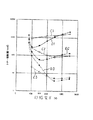
図3及び図4は、かかる事実を明らかにする実験結果の一例を示している。図1に示した画像形成装置を用いて前述の画像形成動作を行い、トナー像の2次転写後の中間転写体表面を第2のクリーニング装置22によってクリーニングしたときと、2次転写作用を受けない中間転写体上のトナーを第2のクリーニング装置22によって除去したときに、中間転写体上と次の記録媒体上にいかなる量のトナーが付着していたかを調べたものである。図3の横軸は、第2のクリーニング装置22のクリーニングローラ23に印加した電圧値を示し、縦軸は中間転写体上又は記録媒体上の1mm2当りの面積中に存在するトナーの個数を示している。
【0041】
図3中の線C1,C2,C3は、先に説明した通常の画像形成動作を行い、2次転写ローラ20による転写電界の作用のもとに、中間転写体上のトナー像を記録媒体S上に2次転写し、その2次転写後の中間転写体表面を第2のクリーニング装置22によりクリーニングしたときの試験結果を示している。このように、線C1,C2,C3は、2次転写ローラ20による2次転写作用を受けた転写残トナーを第2のクリーニング装置22により除去した後のトナーの個数と、このクリーニング時に第2のクリーニング装置22のクリーニングローラ23に印加した電圧値との関係を示しているが、そのうちの線C1は、第2のクリーニング装置22を通過したが、第1の転写領域11を通過する前の中間転写体上、すなわち図1に符号X1で示した中間転写体部分上に、第2のクリーニング装置22によってクリーニングされずに残留しているトナーの個数を示している。また線C2は、第2のクリーニング装置22を通過し、さらに1次転写領域11を通過した中間転写体部分、すなわち図1にX2で示した中間転写体部分に残留するトナーの個数を示している。さらに、線C3は、第2のクリーニング装置22を通過し、さらに1次転写領域11を通過した中間転写体部分が、引き続き次の記録媒体Sが通過中の2次転写領域21を通過し、このときその中間転写体部分にクリーニングし切れずに残っていたトナーがその記録媒体Sの表面X3に転移したときの、その転移したトナーの個数を示している。
【0042】
また、図3における線D1,D2,D3は、共に2次転写作用を受けずに第2のクリーニング装置22に至ったトナーを第2のクリーニング装置22によって除去した後のトナーの個数と、このクリーニング時に第2のクリーニング装置22のクリーニングローラ23に印加した電圧値との関係を示しており、そのうちの線D1は、クリーニング装置22を通過して図1にX1で示した部分に達した中間転写体上にクリーニングされずに残っているトナーの個数を示し、また線D2はクリーニング装置22と1次転写領域11を通過して、図1にX2で示した中間転写体部分に残留しているトナーの個数を示している。さらに、線D3は、第2のクリーニング装置22及び1次転写領域11を通過した中間転写体部分が、次の記録媒体Sが通過している2次転写領域21を通過し、このときその中間転写体部分から当該次の記録媒体Sの表面X3上に転移したトナーの個数を示している。
【0043】
また図4は、横軸に図3と同じくクリーニングローラ23への印加電圧値をとり、その縦軸に、第2のクリーニング装置22によるクリーニング作用を受けた後に中間転写体上に残留するトナーの平均帯電量(μc/g)をとったグラフである。図4中の線Eは、中間転写体上のトナー像を記録媒体S上に2次転写する通常の画像形成動作を行い、その2次転写作用を受けた転写残トナーを第2のクリーニング装置22によって除去した直後の図1にX1で示した中間転写体部分にクリーニングされずに残留したトナーの平均帯電量を示している。また線Fは、2次転写作用を受けない中間転写体上のトナーを第2のクリーニング装置22によって除去した後の図1にX1で示した中間転写体部分に残留するトナーの平均帯電量を示している。
【0044】
図4における電圧0Vのときのトナーの帯電量の値は、クリーニングローラ23への印加電圧が0Vのときのトナー帯電量の値ではなく、第2のクリーニング装置22に達する直前の中間転写体部分、すなわち図1にX4を付した部分に付着するトナーの帯電量を示している。
【0045】
クリーニングされずにX2で示す中間転写体部分に付着するトナーの量と、符号X3で示す記録媒体表面に付着したトナーの量は極めて少量であったため、その帯電量を測定することはできなかった。
【0046】
図4から判るように、クリーニングローラ23への印加電圧の値が高まるに従って、第2のクリーニング装置22を通過した直後(図1のX1の位置)における中間転写体上のトナーの帯電量は、その正規極性とは逆の極性側に増大している。これは、トナーがクリーニング装置22を通るとき、クリーニングローラ23に印加された電圧により形成されるクリーニング電界によって、クリーニングローラ23と中間転写体12との接触部の前後の微小ギャップ領域にて発生するパッシェの放電や、クリーニングローラ23にトナーが接触したときにそのクリーニングローラ23からトナーへの電荷の移動により、当該トナーに正規極性とは逆極性の電荷が加えられるためであると考えられる。
【0047】
また、2次転写作用を受けないトナー(線F)と、この作用を受けたトナー(線E)との帯電量に差があるのは、トナーが2次転写作用を受けたとき、当該トナーが、正規極性とは逆の極性の帯電作用を受けるためである。
【0048】
ここで、第2のクリーニング装置22を通過した直後の中間転写体部分、すなわち図1に符号X1で示した中間転写体部分の表面に残留するトナーを必要に応じて「クリーニング残トナー」と称し、同様に第2のクリーニング装置22を通過し、さらに1次転写領域11を通過した中間転写体部分、すなわち図1に符号X2で示した中間転写体部分の表面に残留するトナーを、必要に応じて「一次転写残トナー」と称することにする。同じく、その1次転写残トナーのうち、次の記録媒体Sに転移したトナーを、必要に応じて「記録媒体転移トナー」と称することにする。
【0049】
図3の線C1及びD1から判るように、2次転写作用を受けたトナーと、その作用を受けないトナーのいずれのトナーの場合も、第2のクリーニング装置22のクリーニングローラ23への印加電圧値が400Vのとき、クリーニング残トナーの量が少なくなっており、特に2次転写作用を受けないトナーの場合、そのクリーニング残トナーの量は最少となっている。
【0050】
上述のように、図3に示した実験例では、2次転写ローラ20による2次転写作用を受けなかった中間転写体上のトナーを第2のクリーニング装置22が除去するときのトナー除去効率は、クリーニングローラ23への印加電圧値が400Vのとき最大となる。これは、クリーニングローラ23への印加電圧が400Vよりも低いと、トナーが中間転写体12からクリーニングローラ23へ転移する向きの電界が弱すぎて、中間転写体のクリーニング効率が低下し、逆にクリーニングローラ23への印加電圧が400Vよりも高くなると、図4からも判るように、2次転写作用を受けないトナーの帯電極性が正規極性とは反対の極性に反転し、正規極性とは逆の極性の電圧を印加されたクリーニングローラ23の側に静電的に引かれるトナーの量が少なくなるためと考えられる。従来は、このような観点から、クリーニングローラ23への印加電圧の値を、中間転写体のクリーニング効率が最も高くなる値、図3の例で言えば400Vに設定し、2次転写作用を受けたトナーも、また当該作用を受けないトナーも、クリーニングローラ23に効率的に転移させ、そのクリーニング効率を高めていたのである。
【0051】
ところが、図3の線C3及びD3から判るように、クリーニングローラ23への印加電圧を400Vに設定した場合、記録媒体転移トナーの量は、クリーニングローラ23への印加電圧が400Vよりも高い場合に比べてむしろ多くなっている。線D3で示した2次転写作用を受けないトナーの場合には、クリーニングローラ23に400Vの電圧を印加したとき、約100個/mm2のトナーが次の記録媒体上に転移している。このような多数のトナーが記録媒体上に転移すれば、そのトナーを薄いハーフトーン状の残像として目視することができ、好ましくない。
【0052】
これに対し、クリーニングローラ23に印加する電圧値が、400Vよりも大きな値となると、第2のクリーニング装置22が中間転写体からトナーを除去する効率は低下するものの、記録媒体転移トナーの量は少なくなる。その理由は次のように推測される。
【0053】
クリーニングローラ23への印加電圧値が400Vより大きくなると、図4から判るように、2次転写作用を受けないトナーも、この作用を受けたトナーも、正規極性とは逆の極性に強く帯電し、クリーニングローラ23への印加電圧が高くなればなる程、その傾向が強まる。一方、1次転写領域11においては、1次転写ローラ3に印加された電圧によって、正規極性に帯電したトナーが感光体2から中間転写体12へ転移する向きの電界が形成されている。従って、正規極性とは逆の極性に帯電した中間転写体12上のクリーニング残トナーが1次転写領域11に至ると、そのトナーの一部が感光体2の表面に静電的に戻される。これは、図3の線C2及びD2からも理解することができる。このように感光体2に戻されたトナーは、感光体上の他の転写残トナーと共に、第1のクリーニング装置14によって感光体表面から除去される。
【0054】
上述のように、クリーニングローラ23に印加する電圧値を400Vよりも大きく設定すると、クリーニング残トナーの一部が感光体2に戻される。しかも、感光体2に転移しなかった中間転写体上の1次転写残トナーは、正規極性と逆の極性に帯電している。このため、このトナーが2次転写領域21に至ったとき、この領域には、中間転写体上の正規極性のトナーが記録媒体上に静電的に転移する向きの電界が形成されているので、上述のように正規極性と逆極性に帯電した1次転写残トナーは記録媒体上に付着し難くなる。このようにして、最終的に次の記録媒体Sに移行する記録媒体転移トナーの量も少なくなり、その記録媒体が転移トナーによって汚される不具合を効果的に抑えることができる。
【0055】
クリーニングローラ23に印加する電圧値が400Vであると、図4の線Fから判るように、2次転写作用を受けないトナーの場合には、そのクリーニング残トナーの平均帯電量が0Vないしはやや正規極性寄りとなっているだけで、このトナーが正規極性と逆極性に強く帯電していることはない。2次転写作用を受けたトナーの場合も、図4の線Eから判るように、そのクリーニング残トナーの平均帯電量は+20μc/g程度で、正規極性と逆の極性に強く帯電していることはない。このようなクリーニング残トナーは、1次転写領域11において感光体2に移行する量は極くわずかであり、図3の線C2及びD2からも判るように、1次転写残トナーの量は多くなる。しかもこの1次転写残トナーは正規極性と逆の極性に強く帯電していることはないので、2次転写領域21において、記録媒体S上に転移しやすくなる。このようにして、図3のC3及びD3からも判るように、記録媒体転移トナーの量が多くなってしまうのである。
【0056】
本例の画像形成装置においては、上述した観点から、第2のクリーニング装置22のクリーニング部材の一例であるクリーニングローラ23に印加する電圧の絶対値が、2次転写手段による2次転写作用を受けなかった中間転写体上のトナーを第2のクリーニング装置22が除去するときのトナー除去効率が最大となるクリーニング部材への印加電圧(図3の例では+400V)の絶対値よりも大きな値に設定されている。これにより、2次転写作用を受けなかったトナーも、その作用を受けたトナーも、第2のクリーニング装置22により除去されるが、このときこのクリーニング装置22でクリーニングされなかったクリーニング残トナーが、効果的に感光体2に戻され、これが第1のクリーニング装置14により回収されるので、記録媒体転移トナーの量を従来よりも効果的に少なくすることができる。
【0057】
なお、クリーニングローラ23への印加電圧が400Vのとき、2次転写作用を受けていないクリーニング残トナーの量は極く少なくなるため、そのトナーの帯電量を測定することができず、このため図4には、このときのトナー帯電量をドットしてプロットしていない。但し、クリーニングローラ23への印加電圧値が400Vの前後の値であるときのトナーの帯電量から、クリーニングローラ23への印加電圧が400Vであるときのトナー帯電量を予測することは可能である。
【0058】
以上のように、クリーニングローラ23に印加する電圧の値を400Vよりも大きくすることにより、記録媒体転移トナーの量を少なくすることができるが、図3を詳細に検討すれば判るように、クリーニングローラ23に印加する電圧の値を、400Vの1.5倍以上である600V以上、特にその2倍である800V以上に設定すると、記録媒体転移トナーの量を非常に少なくすることができる。
【0059】
クリーニングローラ23への印加電圧が600V乃至800Vであるときは、2次転写作用を受けなかったトナーの場合、そのクリーニング残トナーの量は、印加電圧が400Vの場合よりも大幅に増えているが、図4から判るように、そのクリーニング残トナーの帯電極性が正規極性と逆の極性に反転しているので、そのトナーが1次転写領域11を通るとき、多くのトナーが感光体2に転移し、1次転写残トナーの量が最少となっている。しかし、このトナーが1次転写領域11を通るとき、再度、トナーの極性が正規極性の側に反転する作用が働き、正規極性に戻されるトナーが存在するため、記録媒体転移トナーの量が最少となることはない。クリーニングローラ23への印加電圧値が600Vのとき、記録媒体上に約30個/mm2のトナーが転移している。クリーニング残トナーが1次転写領域11を通るとき、そのトナーに、感光体2の側からマイナスの電荷を受け渡されるため、当該トナーの極性が正規極性の側に反転するものと推測される。
【0060】
上述のように、クリーニングローラ23への印加電圧が600乃至800Vのとき、記録媒体転移トナーが最少とはならないが、印加電圧が400Vの場合に比べれば記録媒体転移トナーの量は非常に少なくなる。このような記録媒体転移トナーは、目視上、余程目を凝らさないと、これを残像として認めることはできず、通常、問題となることはない。
【0061】
クリーニングローラ23に印加する電圧が800乃至1200Vになると、クリーニング残トナーの量はさらに増大するが、記録媒体転移トナーの量は10個/mm2以下と最少となり、このような量のトナーは、目視上残像として認められず、実用上全く問題とならぬ量である。
【0062】
上述のようにクリーニングローラ23への印加電圧を800乃至1200Vに設定すると、記録媒体転移トナーが最少となる理由は次のように推測される。図4から判るように、印加電圧が800乃至1200Vとなると、クリーニング残トナーの帯電極性が正規極性とは逆極性に強く反転するため、そのクリーニング残トナーが多量に感光体に戻される。但し、元々クリーニング残トナーの量が多いので、2次転写作用を受けていないトナーの場合、1次転写残トナーの量は、印加電圧が600Vの場合よりも増える。しかし、このクリーニング残トナーは、正規極性とは逆の極性に強く帯電しているので、このトナーが1次転写領域11を通過するとき、再度、トナーの帯電極性が正規極性の側に反転する作用を受けても、1次転写領域通過後の1次転写残トナーは、ほぼ全て正規極性と逆の極性に帯電しており、このためそのトナーが2次転写領域21を通過するとき、記録媒体に転移するトナーの量は極くわずかな量に留まる。
【0063】
記録媒体に転移せずに2次転写領域21を通過した中間転写体上のトナーは、正規極性と逆極性に帯電しているので、このトナーが再び1次転写領域11に至ったとき、その転写電界の作用で効果的に感光体上に転移し、第1のクリーニング装置14に回収される。
【0064】
上述した観点から、本例の画像形成装置においては、クリーニング部材の一例であるクリーニングローラ23に印加する電圧の絶対値が、2次転写手段による2次転写作用を受けなかった中間転写体上のトナーを第2のクリーニング装置22が除去するときのトナー除去効率が最大となるクリーニング部材への印加電圧の絶対値の1.5倍(図3の例では+600V)以上に設定されている。この構成により、記録媒体転移トナーの量を特に効果的に減少させることができる。
【0065】
クリーニングローラ23に印加する電圧の値が1200Vより大きくなると、クリーニング残トナーと1次転写残トナーと記録媒体転移トナーの量は全て増加する傾向を示すが、その増加率は極くわずかであり、クリーニングローラ23への印加電圧値を1200Vよりも大きくしても、記録媒体転移トナーの量を少なく留めることができる。この印加電圧を1400Vに設定したときも、記録媒体転移トナーを、目視上、残像として見分けることはできなかった。
【0066】
但し、クリーニングローラ23への印加電圧を高くしすぎてクリーニング電界が大きくなりすぎると、クリーニングローラ23から中間転写体12への電流のリークが発生し、これが著しくなると、中間転写体が破損して異常画像が発生するおそれがある。図1に示した画像形成装置では、クリーニングローラ23への印加電圧が1600V乃至2000V(2次転写作用を受けないトナーの除去効率が最大となる印加電圧の4乃至5倍)となるとリークが発生し始めるおそれがある。このような点から、クリーニング部材に印加する電圧の絶対値を、2次転写作用を受けなかった中間転写体上のトナーを第2のクリーニング部材が除去するときのトナー除去効率が最大となる値の2乃至3倍(図3の例では+800乃至1200V)に設定することが特に望ましい。
【0067】
図4の線Fから判るように、2次転写作用を受けなかったトナーが第2のクリーニング装置22に至る前の平均帯電量は約−20μc/gである。このトナーが第2のクリーニング装置22を通過した後であって、1次転写領域11に至る前の当該トナーの平均帯電量は、印加電圧が+600Vのときは約+10Vであって、第2のクリーニング装置22に至る前のトナーの帯電量の絶対値の1/2となっている。この値が4倍まで、好ましくは1乃至2倍であると、記録媒体転移トナーの量を効果的に少なくすることができる。
【0068】
上述のように、2次転写手段の一例である2次転写ローラ20による2次転写作用を受けずに第2のクリーニング装置22を通過し、かつ1次転写が行われる1次転写領域に至る前の中間転写体上のトナーの平均帯電量の絶対値が、第2のクリーニング装置22に至る前の当該トナーの平均帯電量の絶対値の1/2乃至4倍、好ましくは1乃至2倍となり、かつ第2のクリーニング装置22に至る前と第2のクリーニング装置22を通過した後の当該トナーの帯電極性が互いに逆極性となるように、クリーニング部材の一例であるクリーニングローラ23に印加する電圧の値を設定することにより、記録媒体転移トナーの量を支障なく少なくすることができる。
【0069】
図1及び図2に示した画像形成装置においては、第2のクリーニング装置22のクリーニング部材が、回転駆動されるクリーニングローラ23より成り、そのクリーニングローラ23に付着したトナーを除去する清掃手段が、クリーニングローラ23の表面に圧接してそのクリーニングローラ23の表面に付着したトナーを掻き取り除去するブレード24より成るが、その際、クリーニングローラ23の表面粗さを、トナーの平均粒径と同等か、又はそれ以下に設定すると、クリーニングローラ23の表面にトナーが固着し難くなり、当該クリーニングローラがトナーで汚され難くなって、その清掃も容易となる。例えば、クリーニングローラ23の表面粗さを、トナー平均粒径7.5μmよりも細かいRz2.5μmとする。ブレード24としては例えばポリウレタンブレードを有利に用いることができる。
【0070】
また、図5に示すように、第2のクリーニング装置22のクリーニング部材を、導電性の芯金31と、その外周面に設けられたブラシ32より成ると共に、回転駆動されるブラシローラ33により構成し、そのブラシローラ33を清掃する清掃手段を、ブラシローラ33のブラシ32に当接して該ブラシ32に付着したトナーを叩き落すフリッカー34により構成することもできる。導電性の芯金31に先に説明した値の電圧が印加される。この構成によれば、回転するブラシローラ33のブラシ32が中間転写体上のトナーを掻き分け、中間転写体を外側から見たときに、その奥側となる中間転写体表面に付着したトナーに対しても効果的に掻き取り作用を与え、これを効率よく除去することができる。フリッカー34のコストは低いので、低コストで清掃手段を構成することができる。
【0071】
また図6に示すように、第2のクリーニング装置22のクリーニング部材を、図5の場合と同じく、回転駆動されるブラシローラ33により構成し、その清掃手段を、ブラシローラ33のブラシ32に当接しながら回転し、該ブラシ32に付着したトナーを静電的に回収する回収ローラ35と、該回収ローラ35の表面に付着したトナーを掻き取り除去するブレード36から構成することもできる。回収ローラ35には、ブラシ32に付着したトナーを回収ローラ側に静電的に転移させる向きの電界が形成されるように電圧が印加され、かかる回収ローラが回転しながら、ブラシ32からトナーを吸引する。かかる構成によっても、図5に示した構成と同様の効果を奏することができるほか、ブラシ32の清掃効果をより一層高めることができる。その際、回収ローラ35の表面粗さをトナーの平均粒径と同等か、又はそれ以下に設定すると、回収ローラ周面へのトナーの固着を防止でき、当該回収ローラ35がトナーで汚され難くなってその清掃が容易となる。
【0072】
また、上述のように各種の形態に構成されるクリーニング部材に直接電圧を印加するほか、他の部材を介して、間接的に電圧を印加してもよい。例えば、図6に示したブラシローラ33のブラシ32を中抵抗体により構成し、導電性の回収ローラ35に電圧を印加することによってブラシローラ33に電圧を印加し、中間転写体との間に、トナーをブラシローラ33に転移させるクリーニング電界を形成するように構成することもできる。
【0073】
本発明は、図示した形態以外の各種画像形成装置にも適用できるものである。
【0074】
【発明の効果】
本発明によれば、中間転写体上に残留する正規極性に帯電したトナーを第2のクリーニング装置で除去することにより、中間転写体上に残留するトナーの量を少なくし、その第2のクリーニング装置によりトナー除去効果が最大となる電界よりも大きなクリーニング電界をクリーニング部材と中間転写体との間に形成することによって、第2のクリーニング装置により除去されずに中間転写体上に残留するトナーの極性を正規極性から反転させ、帯電極性が反転したトナーを一次転写領域において効果的に像担持体表面に戻すことができる。このように、中間転写体上のトナーを2度に亘って除去するので、中間転写体上に残留するトナーの量を極く少量にすることができる。しかも、その残されたトナーの極性が正規極性と逆の極性となっているので、そのトナーが次の記録媒体に転移し難くなり、その記録媒体をトナーで汚す不具合を防止できる。
【0075】
また、特に請求項4及び5に係る発明によれば、上記効果をより一層確実なものとすることができる。
【0076】
さらに、請求項1に係る発明によれば、クリーニングローラの表面がトナーで汚され難くなり、その清掃が容易となる。
【0077】
また、請求項2に係る発明によれば、中間転写体上のトナーの除去効果を高めることができる。
【0078】
さらに、請求項3に係る発明によれば、中間転写体上のトナーの除去効果を高めることができると共に、回収ローラがトナーで汚され難くなり、その清掃が容易となる。
【図面の簡単な説明】
【図1】画像形成装置の一例を示す概略断面図である。
【図2】第2のクリーニング装置の拡大図である。
【図3】クリーニングローラへの印加電圧値と、中間転写体上のトナーの量の関係の一例を示すグラフである。
【図4】クリーニングローラへの印加電圧値と、トナーの帯電量の関係の一例を示すグラフである。
【図5】第2のクリーニング装置の他の例を示す断面図である。
【図6】第2のクリーニング装置のさらに他の例を示す断面図である。
【符号の説明】
8 現像装置
12 中間転写体
14 第1のクリーニング装置
22 第2のクリーニング装置
23 クリーニングローラ
24 ブレード
32 ブラシ
33 ブラシローラ
34 フリッカー
35 回収ローラ
36 ブレード
S 記録媒体[0001]
BACKGROUND OF THE INVENTION
The present invention relates to an image carrier on which an electrostatic latent image is formed while being driven so that the surface moves, and a developing device that visualizes the electrostatic latent image as a toner image with toner charged to a normal polarity. An intermediate transfer member driven so that the surface moves, and an electric field in a direction in which the toner charged to the normal polarity is transferred from the image carrier to the intermediate transfer member, so that the toner image on the image carrier is intermediate A primary transfer means for primary transfer onto the transfer member, a first cleaning device for removing residual toner remaining on the surface of the image carrier after the toner image is primarily transferred to the intermediate transfer member, and a normal polarity. A secondary transfer unit that forms an electric field in a direction in which the charged toner is transferred from the intermediate transfer member onto the recording medium and secondarily transfers the toner image on the intermediate transfer member onto the recording medium; and the toner image on the recording medium. Present on the surface of the intermediate transfer member after secondary transfer A second cleaning device that removes transfer residual toner, and the second cleaning device is opposed to the surface of the intermediate transfer member and is applied with a voltage having a polarity opposite to the normal polarity; The present invention relates to an image forming apparatus having a cleaning unit that removes toner transferred to the cleaning member from the surface of an intermediate transfer member.
[0002]
[Prior art]
An image forming apparatus of the above type configured as an electronic copying machine, a printer, a facsimile machine, or a multifunction machine having at least two of these functions is conventionally known. In this type of image forming apparatus, toner images of different colors are superposed on the intermediate transfer member for primary transfer, and the superposed toner images are collectively transferred onto a recording medium for secondary transfer. Can be formed.
[0003]
The transfer residual toner present on the intermediate transfer member after the toner image is secondarily transferred onto the recording medium is removed from the surface of the intermediate transfer member by the second cleaning device. The second cleaning device also serves to remove the toner on the intermediate transfer member that is not affected by the secondary transfer means. For example, when a recording medium causes a conveyance trouble (jam) during the image forming operation, the operation of the image forming apparatus is stopped, and after the recording medium causing the trouble is removed, that is, after the jam processing, the image forming operation resumes. However, at the time of resumption, the toner image formed on the intermediate transfer body upstream of the secondary transfer area in the intermediate transfer body moving direction passes through the secondary transfer area without receiving the secondary transfer action. The toner is removed from the surface of the intermediate transfer member by the second cleaning device. As described above, the second cleaning device removes not only the transfer residual toner on the intermediate transfer member but also the toner on the intermediate transfer member not subjected to the secondary transfer action. If the efficiency, that is, the cleaning efficiency is lowered, the toner remaining on the intermediate transfer member adheres to the next recording medium, and the image quality of the toner image on the recording medium is deteriorated, or the background stain becomes remarkable. I can't escape my shortcomings.
[0004]
Therefore, in the conventional image forming apparatus, the transfer residual toner on the intermediate transfer member and the toner on the intermediate transfer member not subjected to the secondary transfer action can be most efficiently removed by the cleaning member of the second cleaning device. That is, the value of the voltage applied to the cleaning member is set so that the cleaning efficiency by the cleaning member is maximized.
[0005]
However, according to a study by the present inventor, when the value of the voltage applied to the cleaning member is set as described above, a slight amount of toner on the intermediate transfer member that cannot be removed by the second cleaning device is recorded in the next recording. It has been found that there is a problem that the transfer onto the medium tends to occur, the background stain is generated on the next recording medium, and the image quality of the toner image secondarily transferred onto the recording medium is deteriorated.
[0006]
A charger is provided downstream of the secondary transfer area where the toner image is secondarily transferred in the direction of movement of the surface of the intermediate transfer member, and the residual toner on the intermediate transfer member is opposite to its normal polarity by the charger. The transfer residual toner is electrostatically transferred to the image carrier surface side in the primary transfer region where the primary transfer of the toner image is performed, and the transferred toner is cleaned. There has been proposed an image forming apparatus for removing from the surface of an image carrier by a cleaning apparatus for use. The image forming apparatus stops removing the transfer residual toner on the intermediate transfer body by the cleaning apparatus for the intermediate transfer body, returns all of the transfer residual toner to the surface of the image carrier, and cleans the image carrier. Thus, the toner is removed from the image carrier. According to such a configuration, since the amount of transfer residual toner adhering to the intermediate transfer member after the secondary transfer is small, it is transferred to the image carrier and the toner is efficiently used by the image carrier cleaning device. It can be removed well.
[0007]
However, with the image forming apparatus according to the above proposal, it is difficult to remove the toner on the intermediate transfer member that has not been subjected to the secondary transfer action by the secondary transfer unit. That is, when the image forming operation is resumed after the jam processing as described above, the amount of toner existing on the intermediate transfer member is much larger than the transfer residual toner on the intermediate transfer member after the secondary transfer. Moreover, since the toner does not receive the secondary transfer action, it is strongly charged with normal polarity. In the conventional image forming apparatus, a large amount of toner charged to the normal polarity is forcibly charged to a polarity opposite to the normal polarity by the charger, and this is applied to the surface of the image carrier. Although it is returned electrostatically, it is difficult to charge all of a large amount of toner strongly charged to the normal polarity to a polarity opposite to the normal polarity by the charger. For this reason, a large amount of toner that does not transfer to the surface of the image carrier is left on the intermediate transfer member, which may transfer to the next recording medium, and the recording medium may be soiled with toner.
[0008]
[Problems to be solved by the invention]
The present invention has been made on the basis of the above-described novel recognition. The object of the present invention is to increase the amount of toner transferred to the recording medium without being cleaned and remaining on the intermediate transfer member. The object is to propose an image forming apparatus of the type described at the beginning which can be effectively reduced.
[0009]
[Means for Solving the Problems]
In order to achieve the above object, according to the present invention, in the image forming apparatus of the type described at the beginning, the absolute value of the voltage applied to the cleaning member is not subjected to the secondary transfer action by the secondary transfer unit. The cleaning member is set to a value larger than the absolute value of the voltage applied to the cleaning member that maximizes the toner removal efficiency when the second cleaning device removes the toner on the body, and the cleaning member is driven to rotate. The cleaning means comprises a blade that presses against the surface of the cleaning roller and scrapes and removes the toner adhering to the surface of the cleaning roller, and the surface roughness of the cleaning roller is equal to the average particle size of the toner An image forming apparatus characterized in that it is set to be equal to or less than that is proposed.
[0010]
Similarly, in order to achieve the above object, according to the present invention, in the image forming apparatus of the type described at the beginning, the absolute value of the voltage applied to the cleaning member is not subjected to the secondary transfer action by the secondary transfer unit. The toner is set to a value larger than the absolute value of the voltage applied to the cleaning member that maximizes the toner removal efficiency when the second cleaning device removes the toner on the intermediate transfer member, and the cleaning member is driven to rotate. The image forming apparatus is characterized in that the cleaning means comprises a flicker that abuts against the brush of the brush roller and knocks off the toner adhering to the brush.
[0011]
Further, in order to achieve the above object, according to the present invention, in the image forming apparatus of the type described at the beginning, the absolute value of the voltage applied to the cleaning member is not subjected to the secondary transfer action by the secondary transfer unit. The toner is set to a value larger than the absolute value of the voltage applied to the cleaning member that maximizes the toner removal efficiency when the second cleaning device removes the toner on the intermediate transfer member, and the cleaning member is driven to rotate. A collecting roller that rotates while contacting the brush of the brush roller, and electrostatically collects the toner adhering to the brush; and a toner adhering to the surface of the collecting roller. A blade for scraping and removing, and the surface roughness of the collecting roller is set to be equal to or less than the average particle diameter of the toner. It proposes an image forming apparatus (claim 3).
[0012]
4. The image forming apparatus according to
[0013]
5. The image forming apparatus according to
[0015]
DETAILED DESCRIPTION OF THE INVENTION
Embodiments of the present invention will be described below in detail with reference to the drawings.
[0016]
FIG. 1 is a cross-sectional view schematically showing an image forming apparatus according to the present embodiment. Inside the image forming apparatus
[0017]
On the photoreceptor 2, a charging roller 7, which is an example of a charging device, and a developing device 8 positioned on the downstream side of the photoreceptor surface movement direction are opposed to each other. The developing device 8 illustrated here includes a
[0018]
The charging roller 7 rotates while contacting the surface of the photosensitive member 2 rotating in the direction of arrow A, and the surface of the photosensitive member is charged with a predetermined polarity, in the example shown in the figure, by the voltage applied to the charging roller 7. It is uniformly charged to the same negative polarity as the normal polarity. The surface of the photosensitive member thus charged is selectively irradiated with a light-modulated laser beam L emitted from a
[0019]
The toner image is primarily transferred onto the surface of the
[0020]
The above-described
[0021]
The
[0022]
Instead of the
[0023]
The transfer residual toner present on the surface of the photoconductor after the toner image is primarily transferred to the
[0024]
Next, in the same manner as described above, the surface of the photosensitive member is charged by the charging roller 7, and the charged surface is irradiated with the laser beam L to form a second electrostatic latent image on the photosensitive member. The electrostatic latent image is visualized as a magenta toner image by the
[0025]
Subsequently, in exactly the same manner as described above, a cyan toner image and a black toner image are sequentially formed on the photosensitive member by the
[0026]
On the other hand, in the lower region of the image forming apparatus
[0027]
In the illustrated example, the
[0028]
As described above, the
[0029]
The
[0030]
The recording medium S on which the toner image is secondarily transferred from the
[0031]
A toner image on the intermediate transfer member is recorded on the surface of the intermediate transfer member downstream of the
[0032]
A voltage having a polarity opposite to the normal polarity of the charged toner is applied to the cleaning
[0033]
The
[0034]
The above-described image forming operation is sequentially performed, and a full color toner image is sequentially secondarily transferred onto each recording medium S sent to the
[0035]
Instead of superimposing four color toner images on the intermediate transfer member and performing secondary transfer on the recording medium all at once, primary transfer of one to three color toner images on the intermediate transfer member is performed. Secondary transfer can also be performed on the recording medium S.
[0036]
As described above, the image forming apparatus of the present example is configured so that the toner image is formed by the image carrier on which the electrostatic latent image is formed while being driven so that the surface moves, and the toner charged with the electrostatic latent image to the normal polarity. A developing device 8 that visualizes the image, an
[0037]
The surface of the intermediate transfer member after secondary transfer of the toner image is cleaned by the
[0038]
Further, as described above, when the image forming operation is resumed after the jam processing, a large amount of toner adhering to the intermediate transfer member at this time is part of the
[0039]
Therefore, conventionally, as described above, the value of the voltage applied to the cleaning roller is set so that the toner on the intermediate transfer member can be removed most efficiently. However, according to this configuration, the intermediate transfer member portion cleaned by the
[0040]
FIG. 3 and FIG. 4 show an example of experimental results that clarify this fact. The above-described image forming operation is performed using the image forming apparatus shown in FIG. 1, and the surface of the intermediate transfer member after the secondary transfer of the toner image is cleaned by the
[0041]
Lines C1, C2, and C3 in FIG. 3 perform the normal image forming operation described above, and transfer the toner image on the intermediate transfer member to the recording medium S under the action of the transfer electric field by the
[0042]
Further, lines D1, D2, and D3 in FIG. 3 indicate the number of toners after the
[0043]
4, the horizontal axis represents the voltage applied to the cleaning
[0044]
The value of the toner charge amount when the voltage is 0 V in FIG. 4 is not the value of the toner charge amount when the voltage applied to the cleaning
[0045]
Since the amount of toner adhering to the intermediate transfer member portion indicated by X2 without being cleaned and the amount of toner adhering to the surface of the recording medium indicated by symbol X3 were extremely small, the charge amount could not be measured. .
[0046]
As can be seen from FIG. 4, as the value of the applied voltage to the cleaning
[0047]
In addition, there is a difference in charge amount between the toner that does not receive the secondary transfer action (line F) and the toner that receives this action (line E) when the toner receives the secondary transfer action. However, this is because it is charged with a polarity opposite to the normal polarity.
[0048]
Here, the toner remaining on the surface of the intermediate transfer member immediately after passing through the
[0049]
As can be seen from the lines C1 and D1 in FIG. 3, the applied voltage to the cleaning
[0050]
As described above, in the experimental example shown in FIG. 3, the toner removal efficiency when the
[0051]
However, as can be seen from the lines C3 and D3 in FIG. 3, when the applied voltage to the cleaning
[0052]
On the other hand, when the voltage value applied to the cleaning
[0053]
When the voltage applied to the cleaning
[0054]
As described above, when the voltage value applied to the cleaning
[0055]
When the voltage value applied to the cleaning roller is 400 V, as can be seen from the line F in FIG. 4, in the case of toner that does not receive the secondary transfer action, the average charge amount of the cleaning residual toner is 0 V or slightly normal. The toner is not charged strongly with a polarity opposite to the normal polarity only by being closer to the polarity. In the case of the toner subjected to the secondary transfer action, as can be seen from the line E in FIG. 4, the average charge amount of the cleaning residual toner is about +20 μc / g and is strongly charged to the polarity opposite to the normal polarity. There is no. Such cleaning residual toner has a very small amount transferred to the photosensitive member 2 in the primary transfer region 11, and as can be seen from the lines C2 and D2 in FIG. 3, the amount of the primary transfer residual toner is large. Become. In addition, since the primary transfer residual toner is not strongly charged with a polarity opposite to the normal polarity, it is easily transferred onto the recording medium S in the
[0056]
In the image forming apparatus of this example, from the above viewpoint, the absolute value of the voltage applied to the cleaning
[0057]
Note that when the voltage applied to the cleaning
[0058]
As described above, the amount of recording medium transfer toner can be reduced by increasing the value of the voltage applied to the cleaning
[0059]
When the voltage applied to the cleaning
[0060]
As described above, when the applied voltage to the cleaning
[0061]
When the voltage applied to the cleaning
[0062]
As described above, when the applied voltage to the cleaning
[0063]
Since the toner on the intermediate transfer member that has passed through the
[0064]
From the viewpoint described above, in the image forming apparatus of this example, the absolute value of the voltage applied to the cleaning
[0065]
When the value of the voltage applied to the cleaning
[0066]
However, if the applied voltage to the cleaning
[0067]
As can be seen from the line F in FIG. 4, the average charge amount before the toner that has not been subjected to the secondary transfer action reaches the
[0068]
As described above, the
[0069]
In the image forming apparatus shown in FIGS. 1 and 2, the cleaning member of the
[0070]
As shown in FIG. 5, the cleaning member of the
[0071]
Further, as shown in FIG. 6, the cleaning member of the
[0072]
In addition to applying the voltage directly to the cleaning member configured in various forms as described above, the voltage may be applied indirectly through another member. For example, the
[0073]
The present invention can also be applied to various image forming apparatuses other than the illustrated embodiment.
[0074]
【The invention's effect】
According to the present invention, the toner charged to the normal polarity remaining on the intermediate transfer member is removed by the second cleaning device, whereby the amount of toner remaining on the intermediate transfer member is reduced, and the second cleaning is performed. By forming a cleaning electric field between the cleaning member and the intermediate transfer member that is larger than the electric field that maximizes the toner removal effect by the device, the toner remaining on the intermediate transfer member without being removed by the second cleaning device The polarity is reversed from the normal polarity, and the toner having the reversed charging polarity can be effectively returned to the surface of the image carrier in the primary transfer region. Thus, since the toner on the intermediate transfer member is removed twice, the amount of toner remaining on the intermediate transfer member can be made extremely small. In addition, since the polarity of the remaining toner is opposite to the normal polarity, it is difficult for the toner to transfer to the next recording medium, and the problem that the recording medium is stained with toner can be prevented.
[0075]
In particular, according to the inventions according to
[0076]
Furthermore, according to the first aspect of the present invention, the surface of the cleaning roller is hardly contaminated with toner, and the cleaning becomes easy.
[0077]
According to the second aspect of the invention, the toner removal effect on the intermediate transfer member can be enhanced.
[0078]
Furthermore, according to the third aspect of the present invention, the toner removal effect on the intermediate transfer member can be enhanced, and the collecting roller is hardly contaminated with toner, and the cleaning becomes easy.
[Brief description of the drawings]
FIG. 1 is a schematic cross-sectional view illustrating an example of an image forming apparatus.
FIG. 2 is an enlarged view of a second cleaning device.
FIG. 3 is a graph illustrating an example of a relationship between a voltage applied to a cleaning roller and a toner amount on an intermediate transfer member.
FIG. 4 is a graph illustrating an example of a relationship between a voltage applied to a cleaning roller and a charge amount of toner.
FIG. 5 is a cross-sectional view showing another example of the second cleaning device.
FIG. 6 is a cross-sectional view showing still another example of the second cleaning device.
[Explanation of symbols]
8 Development device
12 Intermediate transfer member
14 First cleaning device
22 Second cleaning device
23 Cleaning roller
24 blade
32 brushes
33 Brush roller
34 Flicker
35 Collection roller
36 blades
S Recording medium
Claims (5)
前記クリーニング部材に印加する電圧の絶対値を、前記2次転写手段による2次転写作用を受けなかった中間転写体上のトナーを第2のクリーニング装置が除去するときのトナー除去効率が最大となるクリーニング部材への印加電圧の絶対値よりも大きな値に設定すると共に、前記クリーニング部材が、回転駆動されるクリーニングローラより成り、前記清掃手段が、クリーニングローラの表面に圧接して当該クリーニングローラの表面に付着したトナーを掻き取り除去するブレードより成り、前記クリーニングローラの表面粗さがトナーの平均粒径と同等又はそれ以下に設定されていることを特徴とする画像形成装置。An image bearing member on which an electrostatic latent image is formed while being driven to move the surface, a developing device that visualizes the electrostatic latent image as a toner image with toner charged to a normal polarity, and the surface moves And an intermediate transfer member that is driven to form an electric field in a direction in which the toner charged to the normal polarity is transferred from the image carrier to the intermediate transfer member, and the toner image on the image carrier is placed on the intermediate transfer member. A primary transfer means for primary transfer, a first cleaning device for removing residual toner remaining on the surface of the image carrier after the toner image is primarily transferred to the intermediate transfer member, and a toner charged to a normal polarity. A secondary transfer means for secondary transfer of the toner image on the intermediate transfer body onto the recording medium by forming an electric field in a direction to transfer from the intermediate transfer body onto the recording medium, and the toner image on the recording medium is secondary transferred. Transfer residue on the surface of the subsequent intermediate transfer member And a second cleaning device for removing the toner, the second cleaning device being opposed to the surface of the intermediate transfer body and applied with a voltage having a polarity opposite to the normal polarity, and the intermediate transfer In an image forming apparatus having a cleaning means for removing toner transferred from the body surface to the cleaning member,
The absolute value of the voltage applied to the cleaning member is the maximum toner removal efficiency when the second cleaning device removes the toner on the intermediate transfer member that has not been subjected to the secondary transfer action by the secondary transfer means. The cleaning member is set to a value larger than the absolute value of the voltage applied to the cleaning member, and the cleaning member is composed of a rotationally driven cleaning roller, and the cleaning means is in pressure contact with the surface of the cleaning roller and An image forming apparatus comprising a blade that scrapes and removes toner adhering to the toner, wherein the surface roughness of the cleaning roller is set to be equal to or less than an average particle diameter of the toner.
前記クリーニング部材に印加する電圧の絶対値を、前記2次転写手段による2次転写作用を受けなかった中間転写体上のトナーを第2のクリーニング装置が除去するときのトナー除去効率が最大となるクリーニング部材への印加電圧の絶対値よりも大きな値に設定すると共に、前記クリーニング部材が、回転駆動されるブラシローラより成り、前記清掃手段が、ブラシローラのブラシに当接して該ブラシに付着したトナーを叩き落すフリッカーより成ることを特徴とする画像形成装置。An image bearing member on which an electrostatic latent image is formed while being driven to move the surface, a developing device that visualizes the electrostatic latent image as a toner image with toner charged to a normal polarity, and the surface moves And an intermediate transfer member that is driven to form an electric field in a direction in which the toner charged to the normal polarity is transferred from the image carrier to the intermediate transfer member, and the toner image on the image carrier is placed on the intermediate transfer member. A primary transfer means for primary transfer, a first cleaning device for removing residual toner remaining on the surface of the image carrier after the toner image is primarily transferred to the intermediate transfer member, and a toner charged to a normal polarity. A secondary transfer means for secondary transfer of the toner image on the intermediate transfer body onto the recording medium by forming an electric field in a direction to transfer from the intermediate transfer body onto the recording medium, and the toner image on the recording medium is secondary transferred. Transfer residue on the surface of the subsequent intermediate transfer member And a second cleaning device for removing the toner, the second cleaning device being opposed to the surface of the intermediate transfer body and applied with a voltage having a polarity opposite to the normal polarity, and the intermediate transfer In an image forming apparatus having a cleaning means for removing toner transferred from the body surface to the cleaning member,
The absolute value of the voltage applied to the cleaning member is the maximum toner removal efficiency when the second cleaning device removes the toner on the intermediate transfer member that has not been subjected to the secondary transfer action by the secondary transfer means. The cleaning member is set to a value larger than the absolute value of the voltage applied to the cleaning member, and the cleaning member is composed of a rotationally driven brush roller, and the cleaning means contacts the brush of the brush roller and adheres to the brush. An image forming apparatus comprising flicker for tapping off toner.
前記クリーニング部材に印加する電圧の絶対値を、前記2次転写手段による2次転写作用を受けなかった中間転写体上のトナーを第2のクリーニング装置が除去するときのトナー除去効率が最大となるクリーニング部材への印加電圧の絶対値よりも大きな値に設定すると共に、前記クリーニング部材が、回転駆動されるブラシローラより成り、前記清掃手段が、該ブラシローラのブラシに当接しながら回転し、該ブラシに付着したトナーを静電的に回収する回収ローラと、該回収ローラの表面に付着したトナーを掻き取り除去するブレードとを具備し、前記回収ローラの表面粗さがトナーの平均粒径と同等又はそれ以下に設定されていることを特徴とする画像形成装置。An image bearing member on which an electrostatic latent image is formed while being driven to move the surface, a developing device that visualizes the electrostatic latent image as a toner image with toner charged to a normal polarity, and the surface moves And an intermediate transfer member that is driven to form an electric field in a direction in which the toner charged to the normal polarity is transferred from the image carrier to the intermediate transfer member, and the toner image on the image carrier is placed on the intermediate transfer member. A primary transfer means for primary transfer, a first cleaning device for removing residual toner remaining on the surface of the image carrier after the toner image is primarily transferred to the intermediate transfer member, and a toner charged to a normal polarity. A secondary transfer means for secondary transfer of the toner image on the intermediate transfer body onto the recording medium by forming an electric field in a direction to transfer from the intermediate transfer body onto the recording medium, and the toner image on the recording medium is secondary transferred. Transfer residue on the surface of the subsequent intermediate transfer member And a second cleaning device for removing the toner, the second cleaning device being opposed to the surface of the intermediate transfer body and applied with a voltage having a polarity opposite to the normal polarity, and the intermediate transfer In an image forming apparatus having a cleaning means for removing toner transferred from the body surface to the cleaning member,
The absolute value of the voltage applied to the cleaning member is the maximum toner removal efficiency when the second cleaning device removes the toner on the intermediate transfer member that has not been subjected to the secondary transfer action by the secondary transfer means. The cleaning member is set to a value larger than the absolute value of the voltage applied to the cleaning member, the cleaning member is composed of a rotationally driven brush roller, and the cleaning means rotates while contacting the brush of the brush roller, A collection roller for electrostatically collecting the toner attached to the brush, and a blade for scraping and removing the toner attached to the surface of the collection roller, wherein the surface roughness of the collection roller is an average particle diameter of the toner An image forming apparatus, wherein the image forming apparatus is set to be equal to or lower than the same.
Priority Applications (2)
| Application Number | Priority Date | Filing Date | Title |
|---|---|---|---|
| JP2000050741A JP3859112B2 (en) | 2000-02-28 | 2000-02-28 | Image forming apparatus |
| US09/793,576 US6405002B2 (en) | 2000-02-28 | 2001-02-27 | Image formation apparatus |
Applications Claiming Priority (1)
| Application Number | Priority Date | Filing Date | Title |
|---|---|---|---|
| JP2000050741A JP3859112B2 (en) | 2000-02-28 | 2000-02-28 | Image forming apparatus |
Related Child Applications (1)
| Application Number | Title | Priority Date | Filing Date |
|---|---|---|---|
| JP2006227400A Division JP2006313388A (en) | 2006-08-24 | 2006-08-24 | Image forming device |
Publications (2)
| Publication Number | Publication Date |
|---|---|
| JP2001242719A JP2001242719A (en) | 2001-09-07 |
| JP3859112B2 true JP3859112B2 (en) | 2006-12-20 |
Family
ID=18572494
Family Applications (1)
| Application Number | Title | Priority Date | Filing Date |
|---|---|---|---|
| JP2000050741A Expired - Fee Related JP3859112B2 (en) | 2000-02-28 | 2000-02-28 | Image forming apparatus |
Country Status (2)
| Country | Link |
|---|---|
| US (1) | US6405002B2 (en) |
| JP (1) | JP3859112B2 (en) |
Families Citing this family (50)
| Publication number | Priority date | Publication date | Assignee | Title |
|---|---|---|---|---|
| JP3963638B2 (en) | 2000-09-07 | 2007-08-22 | 株式会社リコー | Image forming apparatus |
| US6611672B2 (en) | 2000-09-26 | 2003-08-26 | Ricoh Company, Ltd. | Image forming apparatus, monocolor image forming apparatus, toner recycling apparatus and intermediate transfer member |
| DE60118486T2 (en) | 2000-09-28 | 2006-11-23 | Ricoh Company, Ltd. | Toner, developer and container for the developer and method and apparatus for image forming |
| US6653037B2 (en) | 2000-11-20 | 2003-11-25 | Ricoh Company, Ltd. | Toner for developing latent electrostatic images, and image forming method and device |
| JP3933385B2 (en) | 2000-11-28 | 2007-06-20 | 株式会社リコー | Toner for electrostatic latent image development and image forming method |
| JP2002251033A (en) | 2001-02-22 | 2002-09-06 | Ricoh Co Ltd | Color toner, its producing method and image forming method |
| US6858365B2 (en) | 2001-03-23 | 2005-02-22 | Ricoh Company, Ltd. | Toner for developing electrostatic latent image, developing method and developing apparatus |
| US6777149B2 (en) | 2001-03-23 | 2004-08-17 | Ricoh Company Limited | Electrophotographic image forming apparatus and process cartridge, and electrophotographic photoreceptor therefor |
| DE60211995T2 (en) | 2001-04-03 | 2007-01-25 | Ricoh Co., Ltd. | Toner, two-component developer, image forming method and apparatus |
| JP4161246B2 (en) * | 2001-05-18 | 2008-10-08 | ブラザー工業株式会社 | Image forming apparatus |
| US6816691B2 (en) | 2001-05-21 | 2004-11-09 | Ricoh Company | Apparatus having endless belt with roughened guide |
| JP2003029545A (en) * | 2001-07-18 | 2003-01-31 | Ricoh Co Ltd | Image forming device |
| EP1296202A3 (en) * | 2001-09-21 | 2003-06-18 | Ricoh Company, Ltd. | Method and apparatus for producing duplex prints and image forming system using the same |
| US6865361B2 (en) * | 2001-11-12 | 2005-03-08 | Seiko Epson Corporation | Transfer belt unit and image forming apparatus using the same |
| US6832058B2 (en) * | 2001-12-20 | 2004-12-14 | Konica Corporation | Image forming apparatus including a maximum charge quantity of toner particles forming useless toner |
| JP2003255769A (en) * | 2002-02-28 | 2003-09-10 | Ricoh Co Ltd | Image forming apparatus |
| US6901234B2 (en) * | 2002-03-18 | 2005-05-31 | Ricoh Company, Ltd. | Image forming apparatus including an intermediate image transfer belt and high resistance contact member |
| JP4292753B2 (en) * | 2002-06-10 | 2009-07-08 | 富士ゼロックス株式会社 | Image forming apparatus |
| JP4207472B2 (en) * | 2002-06-14 | 2009-01-14 | 富士ゼロックス株式会社 | Image forming apparatus |
| US7174124B2 (en) * | 2002-09-13 | 2007-02-06 | Ricoh Company, Ltd. | Tandem color image forming apparatus with an image transfer belt and backup roller |
| JP2004117597A (en) * | 2002-09-24 | 2004-04-15 | Canon Inc | Image forming apparatus |
| EP1424608B1 (en) * | 2002-11-05 | 2015-07-22 | Ricoh Company, Ltd. | Colour image forming apparatus |
| US7136613B2 (en) | 2003-03-10 | 2006-11-14 | Brother Kogyo Kabushiki Kaisha | Multicolor image forming apparatus and image making device |
| US7203433B2 (en) * | 2003-06-25 | 2007-04-10 | Ricoh Company, Ltd. | Apparatus for detecting amount of toner deposit and controlling density of image, method of forming misalignment correction pattern, and apparatus for detecting and correcting misalignment of image |
| JP4778671B2 (en) * | 2003-07-02 | 2011-09-21 | 株式会社リコー | Method for determining resistance change of transfer member used in image forming apparatus |
| US7302203B2 (en) * | 2004-02-16 | 2007-11-27 | Konica Minolta Business Technologies, Inc. | Image forming apparatus |
| JP4393342B2 (en) * | 2004-10-20 | 2010-01-06 | キヤノン株式会社 | Image forming apparatus |
| US7395004B2 (en) * | 2004-10-20 | 2008-07-01 | Canon Kabushiki Kaisha | Image forming apparatus featuring first and second toner removing sequence selected on the basis of a toner amount per unit area |
| JP2006323294A (en) * | 2005-05-20 | 2006-11-30 | Ricoh Co Ltd | Cleaning device for fixing device and image forming apparatus equipped therewith |
| US7751770B2 (en) * | 2005-12-15 | 2010-07-06 | Kyocera Mita Corporation | Image forming apparatus and recovery roller |
| JP5095133B2 (en) * | 2006-06-06 | 2012-12-12 | 株式会社リコー | Method for manufacturing transfer device |
| JP2008129323A (en) * | 2006-11-21 | 2008-06-05 | Ricoh Co Ltd | Transfer device and image forming apparatus |
| JP4903641B2 (en) * | 2007-07-10 | 2012-03-28 | 株式会社リコー | Fixing device |
| JP5142037B2 (en) * | 2008-07-24 | 2013-02-13 | 株式会社リコー | Belt member, transfer device, and image forming apparatus |
| JP5424079B2 (en) * | 2008-08-21 | 2014-02-26 | 株式会社リコー | Fixing apparatus and image forming apparatus |
| JP5423155B2 (en) * | 2008-10-01 | 2014-02-19 | 株式会社リコー | Image forming apparatus |
| JP5233588B2 (en) * | 2008-10-27 | 2013-07-10 | 株式会社リコー | Fixing apparatus and image forming apparatus |
| JP5810684B2 (en) | 2010-11-04 | 2015-11-11 | 株式会社リコー | Image forming apparatus |
| JP5888588B2 (en) | 2010-11-19 | 2016-03-22 | 株式会社リコー | Transfer device and image forming apparatus |
| JP5787207B2 (en) | 2011-03-18 | 2015-09-30 | 株式会社リコー | Image forming apparatus |
| JP5678841B2 (en) | 2011-06-02 | 2015-03-04 | 株式会社リコー | Image forming apparatus |
| JP5900056B2 (en) | 2011-06-08 | 2016-04-06 | 株式会社リコー | Image forming apparatus |
| JP5765073B2 (en) | 2011-06-16 | 2015-08-19 | 株式会社リコー | Image forming apparatus |
| JP5830956B2 (en) | 2011-06-21 | 2015-12-09 | 株式会社リコー | Image forming apparatus |
| JP5696678B2 (en) | 2011-06-28 | 2015-04-08 | 株式会社リコー | Image forming apparatus |
| JP5891628B2 (en) | 2011-07-15 | 2016-03-23 | 株式会社リコー | Image forming apparatus |
| JP5998710B2 (en) | 2011-11-30 | 2016-09-28 | 株式会社リコー | Image forming apparatus |
| JP6083199B2 (en) | 2012-01-11 | 2017-02-22 | 株式会社リコー | Image forming apparatus |
| JP6053390B2 (en) * | 2012-08-20 | 2016-12-27 | キヤノン株式会社 | Image forming apparatus |
| JP2015049407A (en) * | 2013-09-03 | 2015-03-16 | コニカミノルタ株式会社 | Cleaning device and image forming apparatus |
Family Cites Families (10)
| Publication number | Priority date | Publication date | Assignee | Title |
|---|---|---|---|---|
| US5070370A (en) * | 1990-12-24 | 1991-12-03 | Eastman Kodak Company | Image-forming apparatus having a replaceable cartridge and a transfer member cleaning device |
| US5233394A (en) * | 1991-05-29 | 1993-08-03 | Mita Industrial Co., Ltd. | Transfer device for use in an image forming apparatus |
| JP2954812B2 (en) * | 1993-06-14 | 1999-09-27 | 日立工機株式会社 | Bias cleaning device, electrostatic recording device using the same, and operation method thereof |
| JP3342288B2 (en) | 1995-05-23 | 2002-11-05 | キヤノン株式会社 | Image forming device |
| JP3466825B2 (en) | 1996-08-07 | 2003-11-17 | キヤノン株式会社 | Cleaning equipment |
| JP3869929B2 (en) * | 1997-03-04 | 2007-01-17 | キヤノン株式会社 | Image forming apparatus |
| JP3452749B2 (en) | 1997-03-07 | 2003-09-29 | 株式会社日立製作所 | Image forming device |
| JPH1172979A (en) * | 1997-07-01 | 1999-03-16 | Canon Inc | Image forming device |
| US5937254A (en) * | 1997-07-28 | 1999-08-10 | Eastman Kodak Company | Method and apparatus for cleaning remnant toner and carrier particles |
| JP3733249B2 (en) * | 1998-09-12 | 2006-01-11 | キヤノン株式会社 | Image forming apparatus |
-
2000
- 2000-02-28 JP JP2000050741A patent/JP3859112B2/en not_active Expired - Fee Related
-
2001
- 2001-02-27 US US09/793,576 patent/US6405002B2/en not_active Expired - Lifetime
Also Published As
| Publication number | Publication date |
|---|---|
| US20010031159A1 (en) | 2001-10-18 |
| US6405002B2 (en) | 2002-06-11 |
| JP2001242719A (en) | 2001-09-07 |
Similar Documents
| Publication | Publication Date | Title |
|---|---|---|
| JP3859112B2 (en) | Image forming apparatus | |
| JP3598178B2 (en) | Color image forming method | |
| JP4458909B2 (en) | Image forming apparatus | |
| JP2010210859A (en) | Image forming apparatus | |
| JP4214715B2 (en) | Image forming apparatus | |
| JP4059012B2 (en) | Image forming apparatus | |
| JP4622515B2 (en) | Image forming apparatus | |
| JP5212027B2 (en) | Image forming apparatus | |
| JP2008309906A (en) | Image forming apparatus | |
| JP2005092146A (en) | Image forming apparatus, electrifying member, electrifying device, cleaning means and process cartridge | |
| JP2005250047A (en) | Transfer conveyance device | |
| JP2006313388A (en) | Image forming device | |
| JP4310965B2 (en) | Image forming apparatus | |
| JP3694587B2 (en) | Wet image forming device | |
| JP3848207B2 (en) | Image forming apparatus | |
| JP2013057723A (en) | Image forming device | |
| JP2009210933A (en) | Cleaning mechanism and image forming apparatus | |
| JP4701905B2 (en) | Image forming apparatus | |
| JP4744240B2 (en) | Image forming apparatus cleaning device | |
| JP4285118B2 (en) | Image forming apparatus and cleaning apparatus | |
| JP3862426B2 (en) | Image forming apparatus | |
| JP4345365B2 (en) | Image forming apparatus | |
| JPH10143039A (en) | Cleaning device and image forming device | |
| JP2010145685A (en) | Transfer cleaning device and image forming apparatus | |
| JPH05224565A (en) | Carrier removing device for image forming device |
Legal Events
| Date | Code | Title | Description |
|---|---|---|---|
| A621 | Written request for application examination |
Free format text: JAPANESE INTERMEDIATE CODE: A621 Effective date: 20040517 |
|
| A977 | Report on retrieval |
Free format text: JAPANESE INTERMEDIATE CODE: A971007 Effective date: 20060605 |
|
| A131 | Notification of reasons for refusal |
Free format text: JAPANESE INTERMEDIATE CODE: A131 Effective date: 20060628 |
|
| A521 | Request for written amendment filed |
Free format text: JAPANESE INTERMEDIATE CODE: A523 Effective date: 20060825 |
|
| TRDD | Decision of grant or rejection written | ||
| A01 | Written decision to grant a patent or to grant a registration (utility model) |
Free format text: JAPANESE INTERMEDIATE CODE: A01 Effective date: 20060914 |
|
| A61 | First payment of annual fees (during grant procedure) |
Free format text: JAPANESE INTERMEDIATE CODE: A61 Effective date: 20060914 |
|
| R150 | Certificate of patent or registration of utility model |
Free format text: JAPANESE INTERMEDIATE CODE: R150 |
|
| FPAY | Renewal fee payment (event date is renewal date of database) |
Free format text: PAYMENT UNTIL: 20090929 Year of fee payment: 3 |
|
| FPAY | Renewal fee payment (event date is renewal date of database) |
Free format text: PAYMENT UNTIL: 20100929 Year of fee payment: 4 |
|
| FPAY | Renewal fee payment (event date is renewal date of database) |
Free format text: PAYMENT UNTIL: 20110929 Year of fee payment: 5 |
|
| FPAY | Renewal fee payment (event date is renewal date of database) |
Free format text: PAYMENT UNTIL: 20120929 Year of fee payment: 6 |
|
| FPAY | Renewal fee payment (event date is renewal date of database) |
Free format text: PAYMENT UNTIL: 20130929 Year of fee payment: 7 |
|
| LAPS | Cancellation because of no payment of annual fees |