JP3841882B2 - Appearance inspection method and appearance inspection apparatus - Google Patents
Appearance inspection method and appearance inspection apparatus Download PDFInfo
- Publication number
- JP3841882B2 JP3841882B2 JP23578296A JP23578296A JP3841882B2 JP 3841882 B2 JP3841882 B2 JP 3841882B2 JP 23578296 A JP23578296 A JP 23578296A JP 23578296 A JP23578296 A JP 23578296A JP 3841882 B2 JP3841882 B2 JP 3841882B2
- Authority
- JP
- Japan
- Prior art keywords
- image data
- sample
- area
- region
- inspection
- Prior art date
- Legal status (The legal status is an assumption and is not a legal conclusion. Google has not performed a legal analysis and makes no representation as to the accuracy of the status listed.)
- Expired - Fee Related
Links
Images


Landscapes
- Testing Or Measuring Of Semiconductors Or The Like (AREA)
- Image Processing (AREA)
- Image Analysis (AREA)
- Length Measuring Devices By Optical Means (AREA)
- Investigating Materials By The Use Of Optical Means Adapted For Particular Applications (AREA)
Description
【0001】
【発明の属する技術分野】
本発明は,リードフレーム、プリント基板等の工業製品の検査方法および検査装置に関する。
【0002】
【従来の技術】
従来より、試料を撮影した画像データを画像処理することにより、リードフレーム等の試料の外観を検査する一般的な方法としては、「小孔または凹部がある」とか、「局所的に出っ張りがある」等の欠陥の特徴を定義して、定義に対応した箇所を欠陥として抽出する方法が知られているが、この方法においては、欠陥の定義と同一形状の正常な形状が試料にある場合には、欠陥として抽出されてしまい、抽出箇所が真の欠陥部なのか、否か判別できないという問題があった。
【0003】
これに対応する欠陥検出方法として、予め基準試料を撮影し、基準となる画像データを得ておき、その基準画像データと、検査する試料から得られた画像データの差異を比較して欠陥を得る基準画像データ比較欠陥検出方法がある。
検査精度向上の要求に伴い、基準画像データ比較欠陥検出方法においても、高解像度の撮影が可能なCCDラインセンサ等の線状領域撮影手段が、その撮影手段として使用されるようになってきた。
しかし、このようなCCDラインセンサ等の線状領域撮影手段は、撮影する領域が線状であり、試料全体を撮影するには試料もしくは撮影手段を移動させながら撮影を行う為、基準画像データとの比較欠陥検出方法にCCDラインセンサ等の線状領域撮影手段を用いた場合、基準画像データと検査する試料の画像データが精度良く合うことが必要であり、試料ないし線状領域撮影手段を移動する手段に高い精度が求められていた。
基準画像データと検査する試料の画像データが精度良く合うように、試料ないし線状領域撮影手段を高精度に移動させる移動手段を備えるには、価格が高くなり、検査装置の価格が高くなるという問題がある。即ち、高精度に移動させる移動手段を備えることなしでは、精度の低いローラ搬送を用いるフープ状の試料をインラインで検査することができないという問題があった。
また、基準画像データ比較欠陥検出方法においては、基準画像データを得るための基準試料の撮影時期と、検査する試料を撮影する時期が時間的に離れてしまう場合があるが、この場合、撮影のための明るさや試料の製造条件の変化等が原因で、基準画像データと検査する試料の画像データが異なってしまうことがあり、問題となっていた。
【0004】
【発明が解決しようとする課題】
上記のように、リードフレーム等の試料の外観検査を基準画像データとの比較で行い、且つ、CCDラインセンサ等の線状領域撮影手段を用いる場合には、試料ないし線状領域撮影手段を高精度に移動させる移動手段を備えることなしでは、精度の低いローラ搬送を用いるフープ状の試料をインラインで検査することができないという問題や、基準画像データを得るための基準試料の撮影時期と、検査する試料を撮影する時期が時間的に離れてしまうことにより、基準画像データと検査する試料の画像データが異なってしまうという問題があり、これらの対応が求められていた。
本発明は、このような状況のもと、CCDラインセンサ等の線状領域撮影手段を用いて、基準画像データとの比較により欠陥部を検出する外観検査方法において、試料ないし線状領域撮影手段を高精度に移動させる移動手段を備えることなしでも、精度の低いローラ搬送を用いるフープ状の試料をインラインで検査することができる外観検査方法を提供しようとするものである。同時に、基準画像データを得るための基準試料の撮影時期と、検査する試料を撮影する時期が時間的に離さずにできる外観検査方法を提供しようとするものである。
また、本発明の外観検査方法を実施できる外観検査装置を提供しようとするものである。
【0005】
【課題を解決するための手段】
本発明の外観検査方法は、ほぼ一定の速度で一方向へ移動する試料の線状領域を、線状領域撮影手段にて撮影することにより得られた画像データを用いて、試料の外観検査を行う検査方法であって、予め基準試料を用いて検査する試料の検査領域に対応する領域を、線状領域撮影手段にて撮影して基準となる第一の画像データを準備しておき、検査される試料を前記線状領域撮影手段にて撮影して試料の検査領域全体の画像データである第二の画像データを得た後、第二の画像データの欠陥部を検出する単位である処理領域毎に、順次第一の画像データと比較して欠陥部の検出を行い、試料全体の欠陥部の検出を行うもので、且つ、第二の画像データの各処理領域の欠陥部の検出は、第二の画像データの各処理領域に対し、それぞれ、基準となる第一の画像データにおいて、線状領域撮影手段による試料撮影の位置再現精度等から割り出した、検査する試料の処理領域の画像データに類似する画像データを有する一連領域である類似領域を含む検索領域を決めるステップと、第一の画像データの検索領域内の画像データから、処理領域の画像データに類似した画像データをもつ、処理領域と同じサイズの一連領域を抽出し、これを類似領域とするステップと、処理領域の画像データと、類似領域の画像データについて、それぞれ、対応する1画素毎に減算を施し、減算結果が予め定めたレベルを超える箇所または予め定めたレベルを下まわる箇所を欠陥部と判断するステップとを順次有する、一連の処理を行うものであることを特徴とするものである。
そして、上記における類似領域の決定は、処理領域の画像データと、検索領域内の処理領域と同じサイズの一連の線状領域の画像データについて、画素位置を変える毎に、類似性を求める計算を行い、計算結果より類似性の大きい箇所ほど類似していると判断して決めるものであることを特徴とするものである。
そしてまた、上記における類似性を求める計算は、処理領域と検索領域内の処理領域と同じサイズの一連の線状領域について、画素位置を変える毎に、一画素毎もしくは複数画素毎に差分演算を行うもので、演算を行った線状領域(差分領域)の中で最も大きな差分結果の値を代表値とし、該代表値が最小もしくは定められた値よりも小さくなったものを類似しているとするものであることを特徴とするものである。
また、上記において、順次、検査されたN番目の試料を基準試料としてN+1番目の試料を検査するN回目の検査を行うもので、且つ、Nが4以上の場合は、N回目の検査を行う際に、N回目の検査で欠陥部と検出されたものの内、N−1回目の検査において欠陥部と検出された箇所を除き、Nが3以下の場合については、1番目の試料を基準画像として2番目の試料を検査した1回目の検査結果と、2番目の試料を基準画像として3番目の試料を検査した2回目の検査結果とを比較して、1回目の検査結果と2回目の検査結果で検出された箇所が同じ場合、この箇所における欠陥は2番目の試料の欠陥に因るものとし、1回目の検査結果で検出された欠陥箇所が2回目の検査結果で検出されない場合には、この欠陥箇所の検出は1番目の試料の欠陥に因るものとし、1回目の検査結果で検出されず、2回目の検査結果で検出された箇所については、3番目の試料の欠陥に因るものとすることを特徴とするものである。
【0006】
本発明の外観検査方法は、上記のように、試料を撮影して得られた第ニの画像データの中から、欠陥部を検出する単位である処理領域を決め、処理領域を順次ずらして試料全体の欠陥検出を行うものであるが、処理領域のサイズは検査する対象により適宜決める。
また、ステップとは処理工程である。
【0007】
本発明の外観検査装置は、ほぼ一定の速度で一方向に移動する試料の線状領域を、線状領域撮影手段にて撮影することにより得られた画像データを用いて、試料の外観検査を行う検査装置であって、試料を撮影する線状領域撮影手段と、試料を照明する照明手段と、試料を一方向へ移動させる搬送装置と、撮影された画像データを処理し欠陥検出を行う画像処理部とを備え、予め基準試料を用いて検査する試料の検査領域に対応する領域を、線状領域撮影手段にて撮影して基準となる第一の画像データを準備しておき、検査される試料を前記線状領域撮影手段にて撮影して試料の検査領域全体の画像データである第二の画像データを得た後、第二の画像データの欠陥部を検出する単位である処理領域毎に、順次第一の画像データと比較して欠陥部の検出を行い、試料全体の欠陥部の検出を行うもので、且つ、前記画像処理部は、第二の画像データの各処理領域に対し、それぞれ、基準となる第一の画像データにおいて、線状領域撮影手段による試料撮影の位置再現精度等から割り出した、検査する試料の処理領域の画像データに類似する画像データを有する一連領域である類似領域を含む検索領域を決める処理と、第一の画像データの検索領域内の画像データから、処理領域の画像データに類似した画像データをもつ、処理領域と同じサイズの一連領域を抽出し、これを類似領域とする処理と、処理領域の画像データと、類似領域の画像データについて、それぞれ、対応する1画素毎に減算を施し、減算結果が予め定めたレベルを超える箇所を欠陥部と判断する処理とを順次行うものであることを特徴とするものである。
そして、上記における、画像処理部は、少なくとも線状領域撮影手段で撮影した画像データをA/D変換するA/D変換部、線状領域撮影手段で撮影した画像データをA/D変換してデジタル演算を施す演算装置と、基準試料を線状領域撮影手段で撮影した画像データをA/D変換した画像データ等を蓄積しておくメモリ部とを備えていることを特徴とするものである。
【0008】
【作用】
本発明の外観検査方法は、上記のように構成することにより、CCDラインセンサ等の線状領域撮影手段を用いて、基準画像データとの比較により欠陥部を検出する外観検査方法において、試料ないし線状領域撮影手段を高精度に移動させる移動手段を備えることなしでも、精度の低いローラ搬送を用いるフープ状の試料をインラインで検査することができる外観検査方法の提供を可能としている。また、同時に、基準画像データを得るための基準試料の撮影時期と、検査する試料を撮影する時期が時間的に離さずにできる外観検査方法の提供を可能としている。
即ち、予め基準試料を用いて検査する試料の検査領域に対応する領域を、線状領域撮影手段にて撮影して基準となる第一の画像データを準備しておき、検査される試料を前記線状領域撮影手段にて撮影して試料の検査領域全体の画像データである第二の画像データを得た後、第二の画像データの欠陥部を検出する単位である処理領域毎に、順次第一の画像データと比較して欠陥部の検出を行い、試料全体の欠陥部の検出を行うもので、且つ、第二の画像データの各処理領域の欠陥部の検出は、第二の画像データの各処理領域に対し、基準となる第一の画像データにおいて、線状領域撮影手段による試料撮影の位置再現精度等から割り出した、検査する試料の処理領域の画像データに類似する画像データを有する一連領域である類似領域を含む検索領域を決めるステップと、第一の画像データの検索領域内の画像データから、処理領域の画像データに類似した画像データをもつ、処理領域と同じサイズの一連領域を抽出し、これを類似領域とするステップと、処理領域の画像データと、類似領域の画像データについて、それぞれ、対応する1画素毎に減算を施し、減算結果が予め定めたレベルを超える箇所を欠陥部と判断するステップとを順次有することにより、試料ないし線状領域撮影手段を高精度に移動させる移動手段を備えることなしでも、精度の低いローラ搬送を用いるフープ状の試料をインラインで検査することができる外観検査方法の提供を可能としている。
そして、類似領域の決定は、処理領域の画像データと、検索領域内の処理領域と同じサイズの一連の線状領域の画像データについて、画素位置を変える毎に、類似性を求める計算を行い、計算結果より類似性の大きい箇所ほど類似していると判断して決めるものであり、類似性を求める計算は、処理領域と検索領域内の処理領域と同じサイズの一連の線状領域について、画素位置を変える毎に、一画素毎もしくは複数画素毎に差分演算を行うもので、演算を行った線状領域(差分領域)の中で最も大きな差分結果の値を代表値とし、該代表値が最小もしくは定められた値よりも小さくなったものを類似しているとするものであることにより、比較的簡単に、処理領域と対応した類似領域を求めることができるものとしている。
【0009】
また、順次、検査されたN番目の試料を基準試料としてN+1番目の試料を検査するN回目の検査を行うことにより、検査した試料の画像データをそのまま次の検査試料の基準となる画像データとして用いており、基準画像データを得るための基準試料の撮影時期と、検査する試料を撮影する時期が時間的に離さずに検査できるものとしている。
そして、Nが4以上の場合は、N回目の検査を行う際に、N回目の検査で欠陥部と検出されたものの内、N−1回目の検査において欠陥部と検出された箇所を除き、Nが3以下の場合については、1番目の試料を基準画像として2番目の試料を検査した1回目の検査結果と、2番目の試料を基準画像として3番目の試料を検査した2回目の検査結果とを比較して、1回目の検査結果と2回目の検査結果で検出された箇所が同じ場合、この箇所における欠陥は2番目の試料の欠陥に因るものとし、1回目の検査結果で検出された欠陥箇所が2回目の検査結果で検出されない場合には、この欠陥箇所の検出は1番目の試料の欠陥に因るものとし、1回目の検査結果で検出されず、2回目の検査結果で検出された箇所については、3番目の試料の欠陥に因るものとすることにより、確実な欠陥検査を可能としている。
【0010】
本発明の外観検査装置は、本発明の外観検査方法を実施するための装置で、試料ないし線状領域撮影手段を高精度に移動させる移動手段を備えることなしでも、精度の低いローラ搬送を用いるフープ状の試料をインラインで検査することができる外観検査方法の提供を可能としている。
【0011】
【実施例】
本発明の外観検査方法の実施例を挙げ図に基づいて説明する。
図1は本実施例の外観検査方法のフロー図であり、図2は外観検査装置および外観検査をしている状態を示した概略図であり、図3は検索領域を説明するための図であり、図4は類似性を求める方法を説明するための図であり、図5は欠陥部を説明するための図である
本実施例はエッチング加工等により外形加工されたリードフレーム等の外観検査等に適用できる外観検査方法であり、図2に示す構成の外観検査装置を用いて試料の外観検査を行ったものである。
図2中、110はCCDラインセンサカメラ(線状領域撮影手段)、120は試料(リードフレーム)、130は反射照明、140は透過照明、150は試料巻取り部、160は試料巻き出し部、170は制御部、180表示部、190はマークセンサーである。
尚、リードフレームの場合、一部がフープ状の素材に連結するようにして固定され、多数素材に面付けされた状態で、エッチング加工等により外形加工され、必要に応じて、マーク部を付けた状態で加工する。
【0012】
図2に示すように、本実施例の外観検査方法は、試料(リードフレーム)120をほぼ一定の速度で一方向に移動させながら、且つ試料の撮影する側からは反射照明130で、試料の撮影する側と反対側からは透過照明140により試料120を照明しながら、CCDラインセンサカメラ(線状領域撮影手段)110にて試料120を撮影し、得られた試料の画像データと基準画像データとを比較することにより試料の外観検査を行う方法である。
【0013】
先ず、基準となる基準画像データ(第一の画像データ)を、基準試料から予め作成しておき(S110)、図2に示すCCDラインセンサカメラ(線状領域撮影手段)110にて試料の撮影を行い、試料全体の画像データ(第二の画像データ)を得る。(S120) 第二の画像データの中から欠陥検出処理を行う処理領域を逐次決めて(S130)、以下の処理を第二の画像データにおける処理領域毎に行う。
本実施例では第二の画像データにおける処理領域のサイズを1画素×128画素としている。
次いで、検査する試料の処理領域、即ち外観検査により欠陥部を検出する単位領域の画像データに類似する画像データを有する一連領域である類似領域を含む検索領域を基準画像データ(第一の画像データ)の中で決める。(S140)
検索領域の決定は、試料の各処理領域の画像データに対し、基準となる第一の画像データの、線状領域撮影手段による試料撮影の位置再現精度から割り出す。
即ち、試料に予め設けられたマーク一を図2に示すマークセンサー190からその位置を検出しながら、線状領域撮影手段による試料撮影の位置再現精度を考慮して決める。
図3(a)は第二の画像データ310における処理領域312を示したもので、図3(b)は処理領域に対応する第一の画像データ位置から前後、左右に30画素分大きくした第一の画像データ320における検索領域324を示した図である。
図3(b)の場合は、処理領域312に対応する画像データの位置はマークセンサーから判断され、その位置から前後、左右に30画素分大きくするのは、試料撮影の位置再現精度から決められたものである。
次に、第一の画像データの検索領域内の画像データから、試料の処理領域の画像データに類似した画像データをもつ、処理領域と同じサイズの一連領域を抽出し、これを類似領域として抽出する。(S150)
図4に示すように、検索は矢印方向に1画素ずつずらし、図3(a)に示す第ニの画像データにおける処理領域1画素×128画素に対応するように、第一の画像データの検索領域(図4の410)内の一連の128画素(照合領域420)について、第ニの画像データにおける処理領域との差分演算を行い、各照合領域420毎に類似性を求める。
図4中、410は検索領域、420は照合領域である。
本実施例では、各演算を行った照合領域(差分領域)毎に、その中で最も大きな差分結果の値を代表値とし、全ての照合領域に対する代表値の内、最小もしくは定められた値よりも小さくなった照合領域を類似領域とする。
次いで、試料の第ニの画像データにおける処理領域の画像データと、第一の画像データにおける類似領域の画像データについて、それぞれ、対応する1画素毎に減算を施し(S160)、減算結果が予め定めたレベルを超える箇所または予め定めたレベルを下まわる箇所を欠陥部と判断する。(S170)
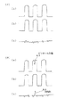
図5(イ)(a)は欠陥の無い処理領域のデータをグラフ化したもので、図5(イ)(b)は欠陥のない類似領域をグラフ化したもので、図5(イ)(c)は、この場合の処理領域、類似領域間で減算した結果のデータをグラフ化したもので、欠陥のないデータ同志の減算の結果はすべて0に近い値になることが分かる。
これに対し、図5(ロ)(a)はピンホール欠陥を撮影したデータを含む処理領域をグラフ化したもので、図5(ロ)(b)は欠陥のない類似領域をグラフ化したもので、図5(ロ)(c)は、この場合の処理領域、類似領域間で減算した結果のデータをグラフ化したものであるが、減算の結果は、図5(ロ)(c)のA0のように0に近い値にならない欠陥部が検出される。
尚、図5(ロ)(a)に示すように、ピンホール欠陥部A1は反射照明で撮影するとその部分のみが暗くなり、その部分の撮影データの値が小さくなる。
【0014】
このようにして、処理領域を順次ずらして、試料全体の欠陥検出を行う。
【0015】
尚、基準画像データを得るには、予め基準試料を撮影しておいて、検査を行う際にこれを用いることもできるが、試料のN番目の画像データをN+1番目の画像データの基準画像データとして用いることにより、基準画像データの作成と検査との時間的なずれを無くすことも可能である。
この場合には、Nが4以上の場合は、N回目の検査を行う際に、N回目の検査で欠陥部と検出されたものの内、N−1回目の検査において欠陥部と検出された箇所を除き、Nが3以下の場合については、1番目の試料を基準画像として2番目の試料を検査した1回目の検査結果と、2番目の試料を基準画像として3番目の試料を検査した2回目の検査結果とを比較して、1回目の検査結果と2回目の検査結果で検出された箇所が同じ場合、この箇所における欠陥は2番目の試料の欠陥に因るものとし、1回目の検査結果で検出された欠陥箇所が2回目の検査結果で検出されない場合には、この欠陥箇所の検出は1番目の試料の欠陥に因るものとし、1回目の検査結果で検出されず、2回目の検査結果で検出された箇所については、3番目の試料の欠陥に因るものとすることにより、確実な欠陥検査を可能とする。
【0016】
また、本実施例では、2048画素のCCDラインセンサカメラを使用しており、、リードフレームを試料とした場合は、リードフレーム1連分は、図7に示すように2048画素×10000画素程度の長方形の画像データとなる。画像データの中には、本来欠陥検出には必要とされない、図7の斜線部で示す無効領域720があるため、この部分については処理の対象としない方が効率的で、この部分を除いた検査領域710を検査の処理対象領域とする。
ここで1連とはリードフレーム等の外形加工品での連続した製品の面付けを言い、検査領域1単位分である。
尚、フープ状の板にリードフレームを外形加工する場合には、1連を複数個、連続して連ねて加工するのが一般的である。
【0017】
本発明の外観検査装置の実施例を挙げ図に基づいて説明する。
図2は、本実施例装置を示した図で、試料を外観検査している状態を示している。図6は図2に示す実施例の外観検査装置における制御部内の概略構成図であり、図6中、610は制御用演算部、620は画像処理部、630は表示制御部、640は入出力部、650は画像処理用演算部、660はA/D変換部、670はメモリー部である。
本実施例の装置は、本発明の外観検査方法を実施するための装置であり、図2に示すように、ほぼ一定の速度で一方向に移動する試料120の線状領域を、CCDラインセンサカメラ(線状領域撮影手段)120にて撮影することにより得られた画像データを用いて、試料120の外観検査を行う検査装置であって、試料を撮影するCCDラインセンサカメラ(線状領域撮影手段)110と、試料120を照明する照明手段(反射照明130、透過照明140)と、試料120を一方向へ移動させる搬送装置(試料巻取り部150、試料巻き出し部160)と、撮影された画像データを処理し欠陥検出を行う画像処理部をもち全体を制御する制御部170とを備えている。
そして、前述の本発明の外観検査方法の実施例のように、予め基準試料を用いて検査する試料の検査領域に対応する領域を、線状領域撮影手段にて撮影して基準となる第一の画像データを準備しておき、検査される試料を前記線状領域撮影手段にて撮影して試料の検査領域全体の画像データである第二の画像データを得た後、第二の画像データの欠陥部を検出する最小単位である処理領域毎に、順次第一の画像データと比較して欠陥部の検出を行い、試料全体の欠陥部の検出を行うものである。
【0018】
制御部170は、図6に示すように、全体の動作を統括する制御演算部610と、撮影された画像データを処理する画像処理部620と、表示部630と、図2に示す試料巻取り部150、試料巻き出し部160への入出力をつかさどる入出力部640とを有する。
そして、画像処理部620は、少なくとも図2に示す線状領域撮影手段で撮影した画像データをA/D変換するA/D変換部660、線状領域撮影手段で撮影した画像データをA/D変換してデジタル演算を施す演算部650と、基準試料を線状領域撮影手段で撮影した画像データをA/D変換した画像データ等を蓄積しておくメモリ部670とを備えている。
画像処理部620は、検査試料の第二の画像データの各処理領域に対し、基準となる第一の画像データにおいて、線状領域撮影手段による試料撮影の位置再現精度等から割り出した、検査する試料の処理領域の画像データに類似する画像データを有する一連領域である類似領域を含む検索領域を決める処理と、第一の画像データの検索領域内の画像データから、処理領域の画像データに類似した画像データをもつ、処理領域と同じサイズの一連領域を抽出し、これを類似領域とする処理と、処理領域の画像データと、類似領域の画像データについて、それぞれ、対応する1画素毎に減算を施し、減算結果が予め定めたレベルを超える箇所または予め定めたレベルを下まわる箇所をを欠陥部と判断する処理とを順次行うものである。
【0019】
【効果】
本発明は、上記のように、試料の撮影をCCDラインセンサカメラのような線状領域を撮影する線状領域撮影手段を用い、基準画像データとの比較により試料の欠陥部を検出する外観検査方法において、試料ないし線状領域撮影手段を高精度に移動させる移動手段を備えることなしでも、精度の低いローラ搬送を用いるフープ状の試料をインラインで検査することができる外観検査方法の提供を可能としており、同時に、基準画像データを得るための基準試料の撮影時期と、検査する試料を撮影する時期が時間的に離さずにできる外観検査方法の提供を可能にしている。
また、本発明は、本発明の外観検査方法を実施できる外観検査装置の提供を可能としている。
【図面の簡単な説明】
【図1】本実施例の外観検査方法のフロー図
【図2】本実施例の外観検査装置を概略図
【図3】検索領域の決め方を説明するための図
【図4】類似領域をさがし方を説明するための図
【図5】欠陥部の抽出を説明するための図
【図6】制御部の構成を示した図
【図7】リードフレームを試料とした場合の検査領域を説明するための図
【符号の説明】
110 CCDラインセンサカメラ(線状領域撮影手段)
120 試料(リードフレーム)
130 反射照明
140 透過照明
150 試料巻取り部
160 試料巻き出し部
170 制御部
180 表示部
190 マークセンサー
310 第二の画像データ
312 処理領域
320 第一の画像データ
322 処理領域に対応する領域
324 検索領域
410 検索領域
420 照合領域
610 制御演算部
620 画像処理部
630 表示部
640 入出力部
650 演算部
660 A/D変換部
670 メモリ部
710 検査領域
720 無効領域[0001]
BACKGROUND OF THE INVENTION
The present invention relates to an inspection method and an inspection apparatus for industrial products such as lead frames and printed circuit boards.
[0002]
[Prior art]
Conventionally, as a general method for inspecting the appearance of a sample such as a lead frame by performing image processing on image data obtained by photographing the sample, there are “a small hole or a concave portion” or “a local protrusion”. '' And the like, and a method for extracting a part corresponding to the definition as a defect is known. In this method, when a normal shape having the same shape as the defect definition is present in the sample Is extracted as a defect, and there is a problem that it cannot be determined whether or not the extracted portion is a true defect portion.
[0003]
As a defect detection method corresponding to this, a reference sample is photographed in advance to obtain reference image data, and a defect is obtained by comparing the difference between the reference image data and image data obtained from the sample to be inspected. There is a reference image data comparison defect detection method.
With the demand for improved inspection accuracy, linear area imaging means such as a CCD line sensor capable of high-resolution imaging have come to be used as the imaging means in the reference image data comparison defect detection method.
However, in such a linear area imaging means such as a CCD line sensor, the area to be imaged is linear, and in order to image the entire sample, imaging is performed while moving the sample or the imaging means. When a linear area imaging means such as a CCD line sensor is used in the comparative defect detection method, it is necessary that the reference image data and the image data of the sample to be inspected accurately match each other, and the sample or linear area imaging means is moved. High precision was required for the means to do.
In order to provide the moving means for moving the sample or the linear region imaging means with high accuracy so that the reference image data and the image data of the sample to be inspected are accurately matched, the price becomes high and the price of the inspection apparatus becomes high. There's a problem. That is, there is a problem that a hoop-like sample using low-precision roller conveyance cannot be in-line inspected without providing a moving means for moving with high accuracy.
In addition, in the reference image data comparison defect detection method, there is a case where the shooting time of the reference sample for obtaining the reference image data and the shooting time of the sample to be inspected are separated in time. For this reason, the reference image data and the image data of the sample to be inspected may be different due to the brightness and the change in the manufacturing conditions of the sample.
[0004]
[Problems to be solved by the invention]
As described above, when a visual inspection of a sample such as a lead frame is performed by comparison with reference image data and a linear area imaging unit such as a CCD line sensor is used, the sample or the linear area imaging unit is increased. Without provision of moving means for accurate movement, it is not possible to inline inspect a hoop-shaped sample using low-precision roller conveyance, and the shooting time and inspection of the reference sample for obtaining reference image data Since the time for photographing the sample to be taken is separated in time, there is a problem that the reference image data and the image data of the sample to be inspected are different, and these measures have been required.
Under such circumstances, the present invention provides a sample or linear area imaging means in an appearance inspection method for detecting a defective portion by comparison with reference image data using a linear area imaging means such as a CCD line sensor. It is an object of the present invention to provide an appearance inspection method capable of in-line inspecting a hoop-shaped sample using roller conveyance with low accuracy without providing a moving means for moving the lens with high accuracy. At the same time, it is an object of the present invention to provide an appearance inspection method capable of keeping the time for photographing a reference sample for obtaining reference image data and the time for photographing a sample to be inspected without being separated in time.
It is another object of the present invention to provide an appearance inspection apparatus capable of performing the appearance inspection method of the present invention.
[0005]
[Means for Solving the Problems]
The visual inspection method of the present invention performs visual inspection of a sample by using image data obtained by photographing a linear region of a sample moving in one direction at a substantially constant speed with a linear region photographing means. An inspection method to be performed, in which an area corresponding to an inspection area of a sample to be inspected using a reference sample is previously imaged by a linear area imaging unit, and first image data serving as a reference is prepared and inspected. A process that is a unit for detecting a defective portion of the second image data after obtaining the second image data that is the image data of the entire inspection area of the sample by photographing the sample to be taken by the linear region photographing means For each area, the defect part is detected in comparison with the first image data sequentially, and the defect part of the entire sample is detected, and the defect part in each processing area of the second image data is detected. For each processing area of the second image data ,Respectively, In the first image data serving as a reference, a similar region that is a series of regions having image data similar to the image data of the processing region of the sample to be inspected, calculated from the position reproduction accuracy of the sample photographing by the linear region photographing means, etc. A step of determining a search area to be included, and extracting a series of areas having the same size as the processing area from the image data in the search area of the first image data, and having a similar size to the processing area Subtracting is performed for each corresponding pixel for the step of making the region, the image data of the processing region, and the image data of the similar region, and the subtraction result exceeds a predetermined level or falls below a predetermined level. Sequentially determining a location as a defective portion, Perform a series of processing It is characterized by that.
The determination of the similarity region in the above is performed by calculating the similarity every time the pixel position is changed between the image data of the processing region and a series of linear region image data having the same size as the processing region in the search region. It is characterized in that it is determined by determining that a part having a higher similarity than the calculation result is similar.
In addition, the calculation for obtaining the similarity in the above is performed for each pixel or a plurality of pixels every time the pixel position is changed for a series of linear regions having the same size as the processing region in the processing region and the search region. The value of the largest difference result in the linear area (difference area) in which the calculation is performed is used as a representative value, and the representative value is the smallest or smaller than a predetermined value is similar. It is characterized by the above.
Further, in the above, the N-th inspection in which the N + 1-th sample is inspected sequentially with the N-th sample inspected as a reference sample is performed, and if N is 4 or more, the N-th inspection is performed. In the case where N is 3 or less, except for the portion detected as a defective portion in the N-1th inspection, the first sample is the reference image. The first test result obtained by inspecting the second sample is compared with the second test result obtained by examining the third sample using the second sample as a reference image. If the location detected by the inspection result is the same, the defect at this location is caused by the defect of the second sample, and the defect location detected by the first inspection result is not detected by the second inspection result. The detection of this defect is the first test. The portion detected by the second inspection result and not detected by the first inspection result is caused by the defect of the third sample. is there.
[0006]
The appearance inspection method of the present invention was obtained by photographing a sample as described above. Second picture A processing area, which is a unit for detecting a defective portion, is determined from the image data, and the processing area is sequentially shifted to detect defects in the entire sample. The size of the processing area is appropriately determined depending on the object to be inspected.
A step is a processing step.
[0007]
The appearance inspection apparatus of the present invention performs an appearance inspection of a sample by using image data obtained by photographing a linear region of a sample moving in one direction at a substantially constant speed with a linear region imaging means. An inspection apparatus that performs linear area imaging means for imaging a sample, illumination means for illuminating the sample, a transport device that moves the sample in one direction, and an image for processing the captured image data to detect defects A first image data serving as a reference is prepared by inspecting a region corresponding to the inspection region of the sample to be inspected using the reference sample with a linear region imaging means in advance. A processing area which is a unit for detecting a defective portion of the second image data after obtaining the second image data which is the image data of the entire inspection area of the sample by photographing the specimen to be photographed by the linear area photographing means Each time, it is missing compared to the first image data. Performs detection parts, and performs detection of the defective portion of the entire sample, and, said image processing unit, for each processing region of the second image data, Respectively, In the first image data serving as a reference, a similar region that is a series of regions having image data similar to the image data of the processing region of the sample to be inspected, calculated from the position reproduction accuracy of the sample photographing by the linear region photographing means, etc. A series of areas of the same size as the processing area are extracted from the image data in the search area of the first image data and the image data similar to the image data of the processing area from the processing for determining the search area to include. A process of making a region, a process of subtracting each corresponding pixel for image data of a processing region and image data of a similar region, and determining a portion where the subtraction result exceeds a predetermined level as a defective portion Are sequentially performed.
The image processing unit described above is an A / D conversion unit for A / D converting at least image data captured by the linear region imaging unit, and A / D-converts image data captured by the linear region imaging unit. An arithmetic device for performing digital arithmetic and a memory unit for storing image data obtained by A / D converting image data obtained by imaging a reference sample with a linear region imaging means, are provided. .
[0008]
[Action]
The appearance inspection method of the present invention is configured as described above. In the appearance inspection method for detecting a defective portion by comparison with reference image data using a linear area photographing means such as a CCD line sensor, It is possible to provide an appearance inspection method capable of in-line inspecting a hoop-shaped sample using roller conveyance with low accuracy without providing a moving unit that moves the linear region imaging unit with high accuracy. At the same time, it is possible to provide an appearance inspection method in which the time for photographing the reference sample for obtaining the reference image data and the time for photographing the sample to be inspected can be kept apart from each other in time.
That is, an area corresponding to the inspection area of the sample to be inspected using the reference sample is imaged by the linear area imaging means to prepare first image data as a reference, and the sample to be inspected is After obtaining the second image data, which is image data of the entire inspection area of the sample by photographing with the linear area photographing means, sequentially for each processing area which is a unit for detecting a defective portion of the second image data. The detection of the defective portion is performed in comparison with the first image data, the defective portion of the entire sample is detected, and the detection of the defective portion in each processing region of the second image data is performed by the second image. For each processing area of the data, image data similar to the image data of the processing area of the sample to be inspected calculated from the position reproduction accuracy of the sample imaging by the linear area imaging means in the first image data serving as a reference. Includes similar regions that are a series of regions A step of determining a search area and extracting a series of areas having the same size as the image data of the processing area from the image data in the search area of the first image data, and extracting the similar area And subtracting each corresponding pixel for the image data of the processing region and the image data of the similar region, and determining a portion where the subtraction result exceeds a predetermined level as a defective portion. Providing a visual inspection method capable of in-line inspecting a hoop-shaped sample using low-precision roller conveyance without having a moving means for moving the sample or the linear region imaging means with high accuracy by having the sample sequentially. Is possible.
The determination of the similarity area is performed by calculating the similarity each time the pixel position is changed for the image data of the processing area and the image data of a series of linear areas having the same size as the processing area in the search area, It is determined by determining that similar parts are more similar to the calculation result, and the calculation for calculating the similarity is performed on pixels in a series of linear areas having the same size as the processing areas in the processing area and the search area. Each time the position is changed, a difference calculation is performed for each pixel or for each of a plurality of pixels. The value of the largest difference result in the calculated linear area (difference area) is set as a representative value, and the representative value is By assuming that the minimum or smaller value than the predetermined value is similar, it is possible to obtain a similar region corresponding to the processing region relatively easily.
[0009]
Further, by sequentially performing the N-th inspection in which the N + 1-th sample is inspected with the N-th sample inspected as a reference sample, the image data of the inspected sample is directly used as image data for the next inspection sample. It is assumed that the inspection time of the reference sample for obtaining the reference image data and the time of photographing the sample to be inspected can be inspected without being separated in time.
And, when N is 4 or more, when performing the N-th inspection, except for the portion detected as a defective part in the N-th inspection among those detected as a defective part in the N-th inspection, When N is 3 or less, the first inspection result obtained by inspecting the second sample using the first sample as a reference image, and the second inspection obtained by inspecting the third sample using the second sample as a reference image When the location detected by the first inspection result and the second inspection result is the same when the results are compared, the defect at this location is caused by the defect of the second sample. If the detected defect location is not detected by the second inspection result, the detection of this defect location is caused by the defect of the first sample, and is not detected by the first inspection result, but the second inspection. For the points detected in the results, the third sample is missing. By to be due to, thereby enabling a reliable defect inspection.
[0010]
The appearance inspection apparatus of the present invention is an apparatus for carrying out the appearance inspection method of the present invention, and uses low-precision roller conveyance without providing a moving means for moving a sample or a linear region imaging means with high accuracy. It is possible to provide an appearance inspection method capable of inspecting a hoop-shaped sample in-line.
[0011]
【Example】
An embodiment of the appearance inspection method of the present invention will be described with reference to the drawings.
FIG. 1 is a flowchart of an appearance inspection method according to the present embodiment, FIG. 2 is a schematic view showing a state of an appearance inspection apparatus and appearance inspection, and FIG. 3 is a diagram for explaining a search area. FIG. 4 is a diagram for explaining a method for obtaining similarity, and FIG. 5 is a diagram for explaining a defective portion.
This embodiment is an appearance inspection method that can be applied to an appearance inspection or the like of a lead frame or the like that has been externally processed by etching or the like, and the appearance inspection of a sample is performed using the appearance inspection apparatus having the configuration shown in FIG. .
In FIG. 2, 110 is a CCD line sensor camera (linear area photographing means), 120 is a sample (lead frame), 130 is reflected illumination, 140 is transmitted illumination, 150 is a sample winding unit, 160 is a sample unwinding unit, Reference numeral 170 denotes a control unit, 180 display unit, and 190 a mark sensor.
In the case of a lead frame, a part of the lead frame is fixed so as to be connected to a hoop-shaped material, and externally processed by etching or the like in a state of being faced to a large number of materials, and a mark portion is attached if necessary. Process in the state.
[0012]
As shown in FIG. 2, in the appearance inspection method of this embodiment, the sample (lead frame) 120 is moved in one direction at a substantially constant speed, and from the side where the sample is photographed, the reflected illumination 130 is used. The sample 120 is photographed by the CCD line sensor camera (linear area photographing means) 110 while illuminating the sample 120 with the transmission illumination 140 from the side opposite to the photographing side, and image data and reference image data of the obtained sample are obtained. This is a method for inspecting the appearance of a sample by comparing
[0013]
First, reference image data (first image data) serving as a reference is created in advance from a reference sample (S110), and the CCD line sensor camera (linear area imaging means) 110 shown in FIG. To obtain image data of the entire sample (second image data). (S120) A processing area for performing defect detection processing is sequentially determined from the second image data (S130), and the following processing is performed. In the second image data This is done for each processing area.
In this example In the second image data The size of the processing area is 1 pixel × 128 pixels.
Next, the processing region of the sample to be inspected, that is, the search region including the similar region which is a series of regions having image data similar to the image data of the unit region in which the defect portion is detected by the appearance inspection is set as the reference image data (first image data). ). (S140)
The search area is determined from the position reproduction accuracy of the sample imaging by the linear area imaging means of the first image data as a reference for the image data of each processing area of the sample.
That is, the position of the
FIG. 3 (a) In the second image data 310 The processing area 312 is shown. FIG. 3B is enlarged by 30 pixels from front to back and right and left from the first image data position corresponding to the processing area. In the first image data 320 FIG. 6 is a diagram showing a search area 324.
In the case of FIG. 3B, the position of the image data corresponding to the processing region 312 is determined from the mark sensor, and the increase of 30 pixels from the position to the front, rear, left and right is determined by the position reproduction accuracy of the sample photographing. It is a thing.
Next, from the image data in the search area of the first image data, a series of areas having the same size as the processing area having image data similar to the image data of the processing area of the sample is extracted, and this is extracted as a similar area To do. (S150)
As shown in FIG. 4, the search is shifted by one pixel in the direction of the arrow and is shown in FIG. In the second image data To correspond to the
In FIG. 4, 410 is a search area, and 420 is a collation area.
In this embodiment, for each collation area (difference area) in which each calculation is performed, the value of the largest difference result among them is used as a representative value, and among the representative values for all the collation areas, the minimum or predetermined value is used. The matching region that has become smaller is set as a similar region.
Then the sample In the second image data Processing area image data, In the first image data The image data in the similar region is subtracted for each corresponding pixel (S160), and a portion where the subtraction result exceeds a predetermined level or falls below a predetermined level is determined as a defective portion. (S170)
FIGS. 5 (a) and 5 (a) are graphs of data of processing areas without defects, and FIGS. 5 (a) and 5 (b) are graphs of similar areas without defects. c) is a graph of data obtained as a result of subtraction between the processing region and the similar region in this case, and it can be seen that all the subtraction results of data without defects are close to zero.
On the other hand, FIGS. 5B and 5A are graphs of processing regions including data obtained by photographing pinhole defects, and FIGS. 5B and 5B are graphs of similar regions without defects. FIGS. 5B and 5C are graphs of data obtained by subtraction between the processing area and the similar area in this case. The subtraction results are shown in FIGS. 5B and 5C. A defective portion that does not become a value close to 0, such as A0, is detected.
As shown in FIGS. 5 (a) and 5 (a), when the pinhole defect portion A1 is photographed with reflected illumination, only that portion becomes dark, and the value of the photographing data of that portion becomes small.
[0014]
In this way, the defect detection of the entire sample is performed by sequentially shifting the processing region.
[0015]
In order to obtain the reference image data, it is possible to take a reference sample in advance and use it when performing the inspection. However, the Nth image data of the sample is used as the reference image data of the (N + 1) th image data. As a result, it is possible to eliminate the time lag between the creation of the reference image data and the inspection.
In this case, when N is 4 or more, a portion detected as a defective portion in the N-1th inspection among the portions detected as a defective portion in the Nth inspection when performing the Nth inspection In the case where N is 3 or less, the result of the first inspection in which the second sample was inspected using the first sample as the reference image, and the third sample inspecting 2 using the second sample as the
[0016]
Further, in this embodiment, a 2048 pixel CCD line sensor camera is used, and when the lead frame is used as a sample, one lead frame is about 2048 pixels × 10000 pixels as shown in FIG. It becomes rectangular image data. In the image data, there is an invalid area 720 indicated by a hatched portion in FIG. 7 that is not originally required for defect detection. Therefore, it is more efficient not to process this portion, and this portion is excluded. The inspection area 710 is set as an inspection processing target area.
Here, the term “continuous” refers to imposition of a continuous product with an externally processed product such as a lead frame, and corresponds to one unit of the inspection area.
In the case of external processing of a lead frame on a hoop-shaped plate, it is common to process a plurality of consecutive ones.
[0017]
An example of an appearance inspection apparatus according to the present invention will be described with reference to the drawings.
FIG. 2 is a view showing the apparatus of this embodiment, and shows a state in which the appearance of the sample is inspected. FIG. 6 is a schematic configuration diagram in the control unit of the appearance inspection apparatus of the embodiment shown in FIG. 2. In FIG. 6, 610 is a control calculation unit, 620 is an image processing unit, 630 is a display control unit, and 640 is an input / output. 650 is an image processing calculation unit, 660 is an A / D conversion unit, and 670 is a memory unit.
The apparatus of the present embodiment is an apparatus for carrying out the appearance inspection method of the present invention. As shown in FIG. 2, a linear region of a sample 120 that moves in one direction at a substantially constant speed is used as a CCD line sensor. An inspection apparatus for inspecting the appearance of a sample 120 using image data obtained by imaging with a camera (linear area imaging means) 120, a CCD line sensor camera (linear area imaging) for imaging the sample Means) 110, illumination means for illuminating the sample 120 (reflective illumination 130, transmitted illumination 140), and a transport device (
Then, as in the above-described embodiment of the appearance inspection method of the present invention, the area corresponding to the inspection area of the sample to be inspected using the reference sample in advance is imaged by the linear area imaging means and becomes the reference first. Image data is prepared, and the sample to be inspected is imaged by the linear area imaging means to obtain second image data which is image data of the entire inspection area of the sample, and then the second image data For each processing region, which is the minimum unit for detecting the defective portion, the defective portion is detected in comparison with the first image data, and the defective portion of the entire sample is detected.
[0018]
As shown in FIG. 6, the
Then, the
The
[0019]
【effect】
As described above, the present invention uses a linear area imaging unit that images a linear area, such as a CCD line sensor camera, as described above, and detects a defective portion of the sample by comparison with reference image data. In the method, it is possible to provide an appearance inspection method capable of in-line inspecting a hoop-shaped sample using low-precision roller conveyance without providing a moving means for moving the sample or the linear region imaging means with high accuracy. At the same time, it is possible to provide an appearance inspection method in which the time for photographing the reference sample for obtaining the reference image data and the time for photographing the sample to be inspected can be kept separate.
In addition, the present invention makes it possible to provide an appearance inspection apparatus that can implement the appearance inspection method of the present invention.
[Brief description of the drawings]
FIG. 1 is a flowchart of an appearance inspection method according to the present embodiment.
FIG. 2 is a schematic view of an appearance inspection apparatus according to the present embodiment.
FIG. 3 is a diagram for explaining how to determine a search area;
FIG. 4 is a diagram for explaining how to search for similar regions;
FIG. 5 is a diagram for explaining extraction of a defective portion;
FIG. 6 is a diagram showing a configuration of a control unit
FIG. 7 is a diagram for explaining an inspection area when a lead frame is used as a sample;
[Explanation of symbols]
110 CCD line sensor camera (linear area photographing means)
120 samples (lead frame)
130 Reflective lighting
140 Transmitted illumination
150 Sample winding part
160 Sample unwinding section
170 Control unit
180 display unit
190 Mark sensor
310 Second image data
312 Processing area
320 First image data
322 Area corresponding to processing area
324 search area
410 Search area
420 Verification area
610 Control calculation unit
620 Image processing unit
630 display
640 I / O section
650 arithmetic unit
660 A / D converter
670 memory section
710 Inspection area
720 Invalid area
Claims (6)
Priority Applications (1)
| Application Number | Priority Date | Filing Date | Title |
|---|---|---|---|
| JP23578296A JP3841882B2 (en) | 1996-08-20 | 1996-08-20 | Appearance inspection method and appearance inspection apparatus |
Applications Claiming Priority (1)
| Application Number | Priority Date | Filing Date | Title |
|---|---|---|---|
| JP23578296A JP3841882B2 (en) | 1996-08-20 | 1996-08-20 | Appearance inspection method and appearance inspection apparatus |
Publications (2)
| Publication Number | Publication Date |
|---|---|
| JPH1063856A JPH1063856A (en) | 1998-03-06 |
| JP3841882B2 true JP3841882B2 (en) | 2006-11-08 |
Family
ID=16991172
Family Applications (1)
| Application Number | Title | Priority Date | Filing Date |
|---|---|---|---|
| JP23578296A Expired - Fee Related JP3841882B2 (en) | 1996-08-20 | 1996-08-20 | Appearance inspection method and appearance inspection apparatus |
Country Status (1)
| Country | Link |
|---|---|
| JP (1) | JP3841882B2 (en) |
Families Citing this family (3)
| Publication number | Priority date | Publication date | Assignee | Title |
|---|---|---|---|---|
| JP2012203458A (en) | 2011-03-23 | 2012-10-22 | Fuji Xerox Co Ltd | Image processor and program |
| CN109282761B (en) * | 2018-11-16 | 2022-04-19 | 南京仁恒轴承滚动体有限公司 | Roller pin roughness detection device |
| CN111605064B (en) * | 2019-06-05 | 2021-08-06 | 北新集团建材股份有限公司 | Wallboard quality control method |
-
1996
- 1996-08-20 JP JP23578296A patent/JP3841882B2/en not_active Expired - Fee Related
Also Published As
| Publication number | Publication date |
|---|---|
| JPH1063856A (en) | 1998-03-06 |
Similar Documents
| Publication | Publication Date | Title |
|---|---|---|
| JP4932819B2 (en) | Surface inspection apparatus and method | |
| KR20060060742A (en) | Apparatus and method for automated web inspection | |
| JP2000036044A (en) | Defect integrating processor and defect integrating processing method | |
| KR20050110005A (en) | Detection of macro-defects using micro-inspection inputs | |
| JP2004191112A (en) | Defect examining method | |
| JP3841882B2 (en) | Appearance inspection method and appearance inspection apparatus | |
| EP4010873B1 (en) | Use of an hdr image in a visual inspection process | |
| JP3819597B2 (en) | PTP seal inspection device | |
| JPH01313745A (en) | Inspecting method for colored periodic pattern | |
| JP2000266514A (en) | Method and device for inspecting metallic sheet | |
| JP4206393B2 (en) | Pattern inspection method | |
| JP3035578B2 (en) | Inspection condition determination device, inspection device, and shutter speed determination device | |
| JP2005274325A (en) | Optical type defect inspection method for metal band | |
| JPH0735699A (en) | Method and apparatus for detecting surface defect | |
| JP3657028B2 (en) | Appearance inspection device | |
| JP2683248B2 (en) | Inspection method of colored periodic pattern | |
| JP2005189167A (en) | Bridge inspection device of cap | |
| JP2000036048A (en) | Brightness and darkness inspection device and its method | |
| JPH08118609A (en) | Printing defect inspecting device | |
| JP2803388B2 (en) | Parts inspection equipment | |
| JP3245066B2 (en) | Display panel defect inspection equipment | |
| JPH10321130A (en) | Surface defect inspection device and surface defect inspection method | |
| JPH03205540A (en) | Defect detecting method | |
| JPH03221849A (en) | Method for detecting defect | |
| JPH0552763A (en) | Inspecting apparatus of appearance of semiconductor device |
Legal Events
| Date | Code | Title | Description |
|---|---|---|---|
| A977 | Report on retrieval |
Free format text: JAPANESE INTERMEDIATE CODE: A971007 Effective date: 20060407 |
|
| A131 | Notification of reasons for refusal |
Free format text: JAPANESE INTERMEDIATE CODE: A131 Effective date: 20060411 |
|
| A521 | Written amendment |
Free format text: JAPANESE INTERMEDIATE CODE: A523 Effective date: 20060529 |
|
| TRDD | Decision of grant or rejection written | ||
| A01 | Written decision to grant a patent or to grant a registration (utility model) |
Free format text: JAPANESE INTERMEDIATE CODE: A01 Effective date: 20060801 |
|
| A61 | First payment of annual fees (during grant procedure) |
Free format text: JAPANESE INTERMEDIATE CODE: A61 Effective date: 20060809 |
|
| R150 | Certificate of patent or registration of utility model |
Free format text: JAPANESE INTERMEDIATE CODE: R150 |
|
| FPAY | Renewal fee payment (event date is renewal date of database) |
Free format text: PAYMENT UNTIL: 20090818 Year of fee payment: 3 |
|
| FPAY | Renewal fee payment (event date is renewal date of database) |
Free format text: PAYMENT UNTIL: 20100818 Year of fee payment: 4 |
|
| FPAY | Renewal fee payment (event date is renewal date of database) |
Free format text: PAYMENT UNTIL: 20110818 Year of fee payment: 5 |
|
| FPAY | Renewal fee payment (event date is renewal date of database) |
Free format text: PAYMENT UNTIL: 20110818 Year of fee payment: 5 |
|
| FPAY | Renewal fee payment (event date is renewal date of database) |
Free format text: PAYMENT UNTIL: 20120818 Year of fee payment: 6 |
|
| FPAY | Renewal fee payment (event date is renewal date of database) |
Free format text: PAYMENT UNTIL: 20120818 Year of fee payment: 6 |
|
| FPAY | Renewal fee payment (event date is renewal date of database) |
Free format text: PAYMENT UNTIL: 20130818 Year of fee payment: 7 |
|
| LAPS | Cancellation because of no payment of annual fees |