JP3788322B2 - Radar - Google Patents
Radar Download PDFInfo
- Publication number
- JP3788322B2 JP3788322B2 JP2001350134A JP2001350134A JP3788322B2 JP 3788322 B2 JP3788322 B2 JP 3788322B2 JP 2001350134 A JP2001350134 A JP 2001350134A JP 2001350134 A JP2001350134 A JP 2001350134A JP 3788322 B2 JP3788322 B2 JP 3788322B2
- Authority
- JP
- Japan
- Prior art keywords
- frequency
- signal
- data
- sampling
- radar
- Prior art date
- Legal status (The legal status is an assumption and is not a legal conclusion. Google has not performed a legal analysis and makes no representation as to the accuracy of the status listed.)
- Expired - Fee Related
Links
Images


Classifications
-
- G—PHYSICS
- G01—MEASURING; TESTING
- G01S—RADIO DIRECTION-FINDING; RADIO NAVIGATION; DETERMINING DISTANCE OR VELOCITY BY USE OF RADIO WAVES; LOCATING OR PRESENCE-DETECTING BY USE OF THE REFLECTION OR RERADIATION OF RADIO WAVES; ANALOGOUS ARRANGEMENTS USING OTHER WAVES
- G01S13/00—Systems using the reflection or reradiation of radio waves, e.g. radar systems; Analogous systems using reflection or reradiation of waves whose nature or wavelength is irrelevant or unspecified
- G01S13/02—Systems using reflection of radio waves, e.g. primary radar systems; Analogous systems
- G01S13/06—Systems determining position data of a target
- G01S13/08—Systems for measuring distance only
- G01S13/32—Systems for measuring distance only using transmission of continuous waves, whether amplitude-, frequency-, or phase-modulated, or unmodulated
- G01S13/34—Systems for measuring distance only using transmission of continuous waves, whether amplitude-, frequency-, or phase-modulated, or unmodulated using transmission of continuous, frequency-modulated waves while heterodyning the received signal, or a signal derived therefrom, with a locally-generated signal related to the contemporaneously transmitted signal
- G01S13/345—Systems for measuring distance only using transmission of continuous waves, whether amplitude-, frequency-, or phase-modulated, or unmodulated using transmission of continuous, frequency-modulated waves while heterodyning the received signal, or a signal derived therefrom, with a locally-generated signal related to the contemporaneously transmitted signal using triangular modulation
-
- G—PHYSICS
- G01—MEASURING; TESTING
- G01S—RADIO DIRECTION-FINDING; RADIO NAVIGATION; DETERMINING DISTANCE OR VELOCITY BY USE OF RADIO WAVES; LOCATING OR PRESENCE-DETECTING BY USE OF THE REFLECTION OR RERADIATION OF RADIO WAVES; ANALOGOUS ARRANGEMENTS USING OTHER WAVES
- G01S13/00—Systems using the reflection or reradiation of radio waves, e.g. radar systems; Analogous systems using reflection or reradiation of waves whose nature or wavelength is irrelevant or unspecified
- G01S13/88—Radar or analogous systems specially adapted for specific applications
- G01S13/93—Radar or analogous systems specially adapted for specific applications for anti-collision purposes
- G01S13/931—Radar or analogous systems specially adapted for specific applications for anti-collision purposes of land vehicles
-
- G—PHYSICS
- G01—MEASURING; TESTING
- G01S—RADIO DIRECTION-FINDING; RADIO NAVIGATION; DETERMINING DISTANCE OR VELOCITY BY USE OF RADIO WAVES; LOCATING OR PRESENCE-DETECTING BY USE OF THE REFLECTION OR RERADIATION OF RADIO WAVES; ANALOGOUS ARRANGEMENTS USING OTHER WAVES
- G01S7/00—Details of systems according to groups G01S13/00, G01S15/00, G01S17/00
- G01S7/02—Details of systems according to groups G01S13/00, G01S15/00, G01S17/00 of systems according to group G01S13/00
- G01S7/35—Details of non-pulse systems
- G01S7/352—Receivers
-
- G—PHYSICS
- G01—MEASURING; TESTING
- G01S—RADIO DIRECTION-FINDING; RADIO NAVIGATION; DETERMINING DISTANCE OR VELOCITY BY USE OF RADIO WAVES; LOCATING OR PRESENCE-DETECTING BY USE OF THE REFLECTION OR RERADIATION OF RADIO WAVES; ANALOGOUS ARRANGEMENTS USING OTHER WAVES
- G01S13/00—Systems using the reflection or reradiation of radio waves, e.g. radar systems; Analogous systems using reflection or reradiation of waves whose nature or wavelength is irrelevant or unspecified
- G01S13/02—Systems using reflection of radio waves, e.g. primary radar systems; Analogous systems
- G01S13/50—Systems of measurement based on relative movement of target
- G01S13/58—Velocity or trajectory determination systems; Sense-of-movement determination systems
- G01S13/583—Velocity or trajectory determination systems; Sense-of-movement determination systems using transmission of continuous unmodulated waves, amplitude-, frequency-, or phase-modulated waves and based upon the Doppler effect resulting from movement of targets
- G01S13/584—Velocity or trajectory determination systems; Sense-of-movement determination systems using transmission of continuous unmodulated waves, amplitude-, frequency-, or phase-modulated waves and based upon the Doppler effect resulting from movement of targets adapted for simultaneous range and velocity measurements
-
- G—PHYSICS
- G01—MEASURING; TESTING
- G01S—RADIO DIRECTION-FINDING; RADIO NAVIGATION; DETERMINING DISTANCE OR VELOCITY BY USE OF RADIO WAVES; LOCATING OR PRESENCE-DETECTING BY USE OF THE REFLECTION OR RERADIATION OF RADIO WAVES; ANALOGOUS ARRANGEMENTS USING OTHER WAVES
- G01S7/00—Details of systems according to groups G01S13/00, G01S15/00, G01S17/00
- G01S7/02—Details of systems according to groups G01S13/00, G01S15/00, G01S17/00 of systems according to group G01S13/00
- G01S7/35—Details of non-pulse systems
- G01S7/352—Receivers
- G01S7/356—Receivers involving particularities of FFT processing
Landscapes
- Engineering & Computer Science (AREA)
- Radar, Positioning & Navigation (AREA)
- Remote Sensing (AREA)
- Physics & Mathematics (AREA)
- Computer Networks & Wireless Communication (AREA)
- General Physics & Mathematics (AREA)
- Electromagnetism (AREA)
- Signal Processing (AREA)
- Radar Systems Or Details Thereof (AREA)
Description
【0001】
【発明の属する技術分野】
この発明は、例えばミリ波帯の電波を用いて、車両や人などを探知するレーダに関するものである。
【0002】
【従来の技術】
従来、自動車などの車両に搭載されるレーダとして、連続波レーダの送信信号を周波数変調し、送信と同時に目標からの反射信号を受信して、送信信号と受信信号とのビート信号により、距離および相対速度を測定するようにしたものがあった。このような変調連続波を用いたレーダにおいては、次のような問題があった。
【0003】
すなわち、レーダから目標までの距離が近づく程、送信信号と受信信号の周波数差の信号であるビート信号の周波数が低くなるが、これが観測区間に2周期以下程度の低い周波数となれば、FFTの分解能以下になり、正確なピーク周波数が検出できず、距離の測定が困難になる。また、そのような至近距離からの反射信号によるビート信号の周波数成分は直流近傍のノイズの大きな領域に現れるので、受信系の雑音指数との関係で、近距離の探知性能が劣化する。これらの理由で、自ずとして探知範囲が狭くなってしまう。
【0004】
上記の問題を解消しようとするものとして、▲1▼実開平5−50383号公報および▲2▼特開平11−109026号公報が開示されている。
上記▲1▼に示されているレーダは、FFTの分解能以下の至近距離に相当するビート信号を有効に利用しようとするものである。すなわち、ビート信号を周波数分析した周波数成分のうち、直流成分と、それに隣接する周波数成分のスペクトルレベルが、目標が存在しない場合の所定値よりも増加した時に、至近距離に目標が存在するものと判断する。
【0005】
▲2▼に示されているレーダは、ミキサに入力すべきビート信号を生成する、受信信号と局部発振信号の何れか一方の周波数を中間周波数分だけオフセットさせるものである。
【0006】
また、近距離探知性能の改善とは別の観点で、送受信機のオフセット電圧やA/D変換器のオフセット電圧の影響を取り除くことによって、誤検知を防止し、相対速度、相対距離の誤計算を防止するようにしたものとして、▲3▼特開平10−253750号公報が開示されている。
【0007】
【発明が解決しようとする課題】
ところが、至近距離に目標が存在しなくても、ミキサの出力には直流成分が現れるため、また、FFT演算するためのサンプル数だけ切り出す際に、信号周期とは非同期に切り出す結果、直流成分が現れるため、▲1▼のレーダにおいては、至近距離に目標が存在する場合と存在しない場合とで、ビート信号の直流成分およびそれに隣接する周波数成分のスペクトルレベルの変化は顕著には表れない。その結果、目標存在有無の判定するための閾値の設定が困難であった。
【0008】
また、▲2▼のレーダにおいては、ビート信号の周波数を中間周波数分だけ周波数オフセットさせるための回路を設けなくてはならず、また、そのオフセット分だけ広い周波数範囲に亘って周波数分析を行わなければならないので、サンプリング周波数を高めなければならず、その分、高速な処理能力が要求される。
【0009】
▲3▼のレーダは、送受信機の回路上生じるオフセット電圧やA/D変換器の回路上生じるオフセット電圧を算出するために、送信を停止状態にして、送信信号と受信信号とのビート信号の平均値をオフセット成分として求め、そのオフセット分をA/D変換値に対して定常的に補償するようにしている。
【0010】
ところが、このような送受信機の回路上生じるオフセット電圧やA/D変換器の回路上生じるオフセット電圧を定常的に補償しても、FFTにより周波数分析すべきサンプリングデータを必要なサンプリング区間に切り出す際に、ビート信号の周期とは非同期に切り出す結果、いわゆるトランケーションによりFFTの結果に直流成分が現れる。また、レーダを構成する回路内における信号の反射などにより、FFTの1レンジビン分(周波数分解能)に満たない、すなわちFFTの対象とするサンプリング区間で1周期に満たない場合にも同様の理由により直流成分が現れる。
【0011】
したがって、送受信機の回路上生じるオフセット電圧やA/D変換器の回路上生じるオフセット電圧の補償だけでは、FFTの結果から直流成分を取り除くことはできない。
【0012】
上述の問題は、FMCW方式のような変調連続波を用いたレーダに限らず、例えばパルスドップラーレーダやFSKレーダのように、ドップラーシフト周波数を検出するレーダにおいては、低速度域の速度測定について同様に生じる。
【0013】
この発明の目的は、FMCW方式のような変調連続波レーダにおける、近距離の物標探知を行う場合、またはパルスドップラーレーダやFSKレーダのように、ドップラーシフト周波数を検出するレーダにおける、低速度域の探知を行う場合でも、全体の構成が複雑化せずに、物標の探知を容易に行えるようにしたレーダを提供することにある。
【0014】
【課題を解決するための手段】
この発明は、探知用電波である送信信号を送信し、物標からの反射信号を含む受信信号を受信する手段と、
前記送信信号と前記受信信号との周波数差の信号であるビート信号をサンプリングするとともに、AD変換して所定データ数のサンプリングデータ列を求めるサンプリングデータ列生成手段と、
該サンプリングデータ列のうち周波数分析すべきサンプリング区間の平均値を当該サンプリング区間のそれぞれのデータから減じて被周波数分析データを求める被周波数分析データ生成手段と、
前記被周波数分析データを離散フーリエ変換により周波数分析して、前記ビート信号の周波数成分を求め、該周波数成分から、前記送信信号を前記受信信号として反射する物標の探知を行う手段と、
を備えたことを特徴とする。
【0015】
この構成により、例えばFFTにより周波数分析した際に、分析結果に直流成分が発生しないため、直流成分近傍の低周波域のピークの有無を確実に捉えられるようにする。
【0016】
また、この発明は、前記被周波数分析データ生成手段が、前記サンプリングデータ列の平均値を当該サンプリングデータ列のそれぞれのデータから減じ、さらに窓関数処理を施すことによって被周波数分析データを生成するものとする。すなわち、窓関数処理を施すまでに直流成分を除去しておく。これにより、直流成分近傍に窓関数処理によるスペクトルの広がりが生じるのを防止し、直流成分近傍の低周波域のピークの有無を確実に捉えられるようにする。
【0017】
また、この発明は、前記探知用電波を、周波数が次第に上昇する上り変調区間と、周波数が次第に下降する下り変調区間とが時間的に三角波状に繰り返し変化する周波数変調波とし、前記上り変調区間の前記ビート信号と前記下り変調区間の前記ビート信号とに基づいて、物標の相対距離および相対速度を検出することを特徴とする。
【0018】
この構成により、いわゆるFMCW方式で、至近距離の物標までの距離および相対速度を検出可能とする。
【0019】
【発明の実施の形態】
第1の実施形態に係るレーダの構成を図1〜図5を参照して説明する。
図1はレーダの全体の構成を示すブロック図である。ここでVCO1は、DAコンバータ14より出力される制御電圧に応じて発振周波数を変化させる。アイソレータ2は、VCO1からの発振信号をカプラ3側へ伝送し、VCO1へ反射信号が入射するのを阻止する。カプラ3は、アイソレータ2を経由した信号をサーキュレータ4側へ伝送するとともに、所定の分配比で送信信号の一部をローカル信号Loとしてミキサ6へ与える。サーキュレータ4は、送信信号をアンテナ5側へ伝送し、また、アンテナ5からの受信信号をミキサ6へ与える。アンテナ5は、VCO1のFM変調された連続波の送信信号を送信し、同方向からの反射信号を受信する。また、そのビームの方向を探知角度範囲に亘って周期的に変化させる。
【0020】
ミキサー6は、カプラ3からのローカル信号Loとサーキュレータ4からの受信信号とをミキシングして中間周波信号IFを出力する。IF増幅回路7は、その中間周波信号を、距離に応じた所定の増幅度で増幅する。ADコンバータ8は、その電圧信号をサンプリングデータ列に変換する。DC除去部9はADコンバータ8により求められたサンプリングデータ列のうち、後段のFFTの処理対象となる所定のサンプリング区間の平均値を求める。この平均値は、FFTにより求められる直流成分に等しいので、すべてのサンプリング区間のそれぞれのデータからその平均値を減じる演算処理を行うことにより、FFT演算処理の前に直流成分の除去を行う。
【0021】
ここで、サンプリング区間のデータをf(i) 、サンプリング区間のデータ数をnで表せば、直流成分除去後のサンプリング区間内の時刻tのデータf(t) は次のように表せる。
【0022】
f(t) =f(i) −Σf(i) /n (i=1,2,3,...,n)
ここで、総和演算子Σはi=1〜nについて作用する。
【0023】
FFT演算部11は、直流成分の除去された上記サンプリング区間のデータについて周波数成分を分析する。ピーク検出部12は、予め定めた閾値を超えるレベルの周波数成分につき、その極大位置を検出する。
【0024】
送信波変調部16は、DAコンバータ14に対して変調信号のデジタルデータを順次出力する。これにより、VCO1の発振周波数を三角波状に連続してFM変調させる。また、距離・速度算出部13は、後述するように、送信信号の周波数が次第に上昇する上り変調区間におけるビート信号(以下「アップビート信号」という。)の周波数と、送信信号の周波数が次第に下降する下り変調区間におけるビート信号(以下「ダウンビート信号」という。)の周波数とに基づいて、アンテナから物標までの距離および相対速度を算出し、これらをホスト装置へ出力する。
【0025】
また、DC除去部9、FFT演算部11、ピーク検出部12、距離・速度算出部13は、DSP(ディジタル信号処理回路)等の演算素子17に組み込まれている。すなわち、それらの演算はDSPの演算処理によって行われる。もちろん、これらの信号処理は、DSPで行わずに、専用の集積回路を用いて行うように構成してもよい。
【0026】
図2は、物標までの距離と相対速度に起因する、送信信号と受信信号の周波数変化のずれの例を示している。送信信号の周波数上昇時における送信信号と受信信号との周波数差がアップビートの周波数fBUであり、送信信号の周波数下降時における送信信号と受信信号との周波数差がダウンビートの周波数fBDである。この送信信号と受信信号の三角波の時間軸上のずれ(時間差)が、アンテナから物標までの電波の往復時間に相当する。また、送信信号と受信信号の周波数軸上のずれがドップラシフト量であり、これはアンテナに対する物標の相対速度に起因して生じる。この時間差とドップラシフト量によってアップビートfBUとダウンビートfBDの値が変化する。逆に、このアップビートとダウンビートの周波数を検出することによって、レーダから物標までの距離およびレーダに対する物標の相対速度を算出する。
【0027】
図4は、レーダと物標との位置関係の例を示している。ここでは、至近距離に歩行者が存在し、それより離れた2ヶ所に2台の車が存在している。
【0028】
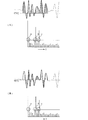
図3は上記直流成分の除去による効果について示している。(A),(B)において、図における上側は時間波形、下側はその周波数スペクトルを表している。また、(A)は直流成分除去前の状態、(B)は直流成分除去後の状態を示している。この例では、(A),(B)の何れの場合にも、周波数スペクトルのa,b,cで示す部分でレベルが閾値を超えている。a部分は図4における歩行者、b,c部分は図4における2台の車に相当する。しかし、aで示す直流成分またはその近傍の周波数成分は、至近距離に存在する物標に起因するものであるのか、回路構成上または信号処理上重畳された成分であるのかの判定が困難である。そのため、従来は、直流成分近傍についてはピーク検出を正しく行うことができないものとして、所定周波数より低周波数域についてはピーク検出を行っていない。
【0029】
これに対し、(B)に示すように、直流成分を除去した結果をFFT処理した場合には、周波数スペクトルの直流成分(破線)が表れないので、aで示す部分のピークの検出が容易となって、至近距離の物標の有無検知が可能となる。
【0030】
図5は、図1に示したDSPなどの演算素子17によって距離および速度の測定を行う処理手順を示すフローチャートである。
まず、上り変調区間内の所定サンプリング区間のデータを取り込む(n1)。続いて、取り込んだデータの平均値を算出し、その平均値をサンプリング区間の各データから減じる(n2→n3)。その後、上記平均値を減じたサンプリング区間の各データをFFT(高速フーリエ変換)処理することによって、アップビート信号の周波数成分を求める(n4)。
【0031】
次に、下り変調区間内の所定サンプリング区間のデータを取り込む(n5)。続いて、取り込んだデータの平均値を算出し、その平均値をサンプリング区間の各データから減じる(n6→n7)。その後、上記平均値を減じたサンプリング区間の各データをFFT(高速フーリエ変換)処理することによって、ダウンビート信号の周波数成分を求める(n8)。
【0032】
その後、アップビート信号の周波数成分のうちレベルが突出する位置の周波数(以下「ピーク周波数」という。)と、ダウンビート信号の周波数成分のうちピーク周波数をそれぞれ検出し、ペアリングを行う(n9)。すなわち、アップビート信号の周波数成分に現れたピーク周波数と、ダウンビート信号の周波数成分に現れたピーク周波数とについて、同じ物標に起因して生じたピーク周波数同士の組み合わせを判定する。
【0033】
その後、ペアとなるアップビート信号のピーク周波数とダウンビート信号のピーク周波数との和に基づき、レーダから物標までの距離を算出する(n10)。また、アップビート信号のピーク周波数とダウンビート信号のピーク周波数との差に基づき、レーダに対する物標の相対速度を算出する(n11)。
【0034】
次に、第2の実施形態に係るレーダの構成をブロック図として図6に示す。図6において、窓関数処理部15は、DC除去部9により直流成分が除去されたデータについて、所定形状の窓関数を用いてデータの切り出しを行う。この窓関数による切り出しによって、時間波形を有限のサンプリング区間に切り出してFFT演算する際に生じるトランケーションによる誤差を抑える。例えばハニング窓・ハミング窓・ブラックマン=ハリス窓等の窓関数処理を行う。その他の構成は図1に示したものと同様である。
【0035】
このように窓関数処理を施すことにより、その窓関数の形によってメインローブの広がりとサイドローブの広がりおよび減衰量が様々に変化するが,直流成分を除去した結果に対して窓関数処理を施すことにより、直流成分の影響を受けずに、高い周波数分解能を維持することができる。
【0036】
図7は、窓関数を施した後にDC除去を行った場合と、窓関数を施す前にDC除去を行った場合とについて、スペクトルの変化を示している。
【0037】
窓関数処理を施した後に直流成分を除去することにすれば、すなわち直流成分を除去することなく窓関数を施せば、図7の(A)に示すように、直流成分近傍のスペクトルが広がり、そのピーク位置の検出および物標有無の判定が困難となる。これに対し、窓関数を施す前にDC除去を行えば、(B)に示すように、直流成分近傍のスペクトルが広がることなく、直流成分付近のピーク位置の検出および物標有無の判定が容易となる。
【0038】
なお、このように、周期波形を有限の時間幅で切り出すことにより、上記トランケーションによるスペクトルの広がりが生じるので、閾値を超える範囲について、強度が極大値をとる周波数位置をピーク周波数として求める。
【0039】
なお、以上に示した各実施形態では、FMCW方式のレーダについて示したが、パルスドップラーレーダやFSKレーダのように、ドップラーシフト周波数を検出するレーダにおいても、ビート信号の周波数分析を行う部分に同様に適用できる。
【0040】
また、以上に示した実施形態においては、周波数分析のために、高速フーリエ変換(FFT)を用いたが、周波数分析手法としてFFTに限られるものではない。周波数分析すべきサンプリングデータを必要なサンプリング区間に切り出す際に、いわゆるトランケーションにより、周波数分析の結果に直流成分が現れる離散フーリエ変換であれば、同様に適用できる。
【0041】
【発明の効果】
この発明によれば、サンプリングデータ列のうち周波数分析すべきサンプリング区間の平均値を当該サンプリング区間のそれぞれのデータから減じて被周波数分析データを求める被周波数分析データ生成手段を設け、直流成分除去後の信号を周波数分析するようにしたので、FFTなどにより離散周波数分析した際に、分析結果に直流成分が発生しない。そのため、直流成分近傍の低周波域のピークの有無を確実に捉えられるようになる。その結果、FMCW方式のような変調連続波レーダにおける、近距離の物標探知を行う場合、またはパルスドップラーレーダやFSKレーダのように、ドップラーシフト周波数を検出するレーダにおける、低速度域の探知を行う場合でも、全体の構成が複雑化せずに、物標の探知を容易に行えるようになる。
【0042】
また、この発明によれば、窓関数処理を施すまでに直流成分を除去することにより、直流成分近傍に窓関数処理によるスペクトルの広がりが生じるのが防止でき、直流成分近傍の低周波域のピークの有無が確実に捉えられるようになる。
【0043】
また、この発明によれば、前記探知用電波を、周波数が次第に上昇する上り変調区間と、周波数が次第に下降する下り変調区間とが時間的に三角波状に繰り返し変化する周波数変調波とし、上り変調区間のビート信号と下り変調区間のビート信号とに基づいて、アンテナから物標までの距離および相対速度の検出が同時に可能となる。
【図面の簡単な説明】
【図1】第1の実施形態に係るレーダの構成を示すブロック図
【図2】レーダから物標までの距離およびレーダに対する物標の相対速度により変化する送信信号と受信信号の周波数変化の例を示す図
【図3】中間周波信号とその周波数スペクトルとを示す図
【図4】レーダと物標との位置関係の例を示す図
【図5】距離および相対速度の検知のための処理手順を示すフローチャート
【図6】第2の実施形態に係るレーダの構成を示すブロック図
【図7】同レーダにおける周波数スペクトルの例を示す図
【符号の説明】
17−演算素子
ADC−ADコンバータ
DAC−DAコンバータ
VCO−電圧制御発振器[0001]
BACKGROUND OF THE INVENTION
The present invention relates to a radar that detects vehicles, people, and the like using, for example, millimeter-wave radio waves.
[0002]
[Prior art]
Conventionally, as a radar mounted on a vehicle such as an automobile, a transmission signal of a continuous wave radar is frequency-modulated, a reflection signal from a target is received simultaneously with transmission, and a beat signal between the transmission signal and the reception signal is used. Some of them measured relative speed. The radar using such a modulated continuous wave has the following problems.
[0003]
In other words, the closer the distance from the radar to the target, the lower the frequency of the beat signal, which is the signal of the frequency difference between the transmission signal and the reception signal, but if this becomes a low frequency of about two cycles or less in the observation interval, the FFT It becomes below the resolution, the accurate peak frequency cannot be detected, and the distance measurement becomes difficult. Further, since the frequency component of the beat signal due to the reflected signal from such a close distance appears in a large noise area near the direct current, the detection performance at a short distance deteriorates in relation to the noise figure of the receiving system. For these reasons, the detection range is naturally narrowed.
[0004]
In order to solve the above problems, (1) Japanese Utility Model Laid-Open No. 5-50383 and (2) Japanese Patent Laid-Open No. 11-109026 are disclosed.
The radar shown in the above (1) intends to effectively use a beat signal corresponding to a close distance below the resolution of FFT. That is, among the frequency components obtained by frequency analysis of the beat signal, when the spectrum level of the DC component and the frequency component adjacent thereto increases from a predetermined value when there is no target, the target exists at a close distance. to decide.
[0005]
The radar shown in (2) is for offsetting the frequency of either the reception signal or the local oscillation signal, which generates a beat signal to be input to the mixer, by an intermediate frequency.
[0006]
In addition to improving the short-range detection performance, by removing the influence of the offset voltage of the transceiver and the offset voltage of the A / D converter, false detection is prevented and the relative speed and relative distance are miscalculated. (3) Japanese Patent Laid-Open No. 10-253750 has been disclosed as a means for preventing the above.
[0007]
[Problems to be solved by the invention]
However, even if there is no target at a close distance, a DC component appears in the output of the mixer. Also, when extracting only the number of samples for FFT calculation, the DC component is extracted asynchronously with the signal period. Therefore, in the radar of (1), the change in the spectral level of the DC component of the beat signal and the frequency component adjacent to it does not appear remarkably depending on whether or not the target exists at a close range. As a result, it has been difficult to set a threshold value for determining whether or not a target exists.
[0008]
In addition, in the radar of (2), a circuit for offsetting the frequency of the beat signal by the intermediate frequency must be provided, and frequency analysis must be performed over a wide frequency range by the offset. Therefore, it is necessary to increase the sampling frequency, and accordingly, high speed processing capability is required.
[0009]
In order to calculate the offset voltage generated on the transmitter / receiver circuit and the offset voltage generated on the A / D converter circuit, the radar of (3) stops the transmission and generates the beat signal between the transmission signal and the reception signal. An average value is obtained as an offset component, and the offset is steadily compensated for the A / D conversion value.
[0010]
However, even when the offset voltage generated on the circuit of the transceiver and the offset voltage generated on the A / D converter circuit are steadily compensated, sampling data to be subjected to frequency analysis by FFT is cut out to a necessary sampling section. In addition, as a result of cutting out asynchronously with the cycle of the beat signal, a direct current component appears in the FFT result by so-called truncation. For the same reason, direct current is also applied to the case where the signal is less than one range bin (frequency resolution) of the FFT, that is, less than one cycle in the sampling interval to be FFT, due to signal reflection in the circuit constituting the radar. Ingredients appear.
[0011]
Therefore, the direct current component cannot be removed from the FFT result only by compensating for the offset voltage generated on the circuit of the transceiver and the offset voltage generated on the circuit of the A / D converter.
[0012]
The above-mentioned problem is not limited to radar using a modulated continuous wave as in the FMCW system. For example, in a radar that detects a Doppler shift frequency, such as pulse Doppler radar and FSK radar, the same applies to velocity measurement in the low-speed range. To occur.
[0013]
An object of the present invention is to perform a low-speed range in a short-range target detection in a modulated continuous wave radar such as the FMCW system, or in a radar that detects a Doppler shift frequency, such as a pulse Doppler radar or an FSK radar. It is an object of the present invention to provide a radar that can easily detect a target without complicating the overall configuration even when detecting the target.
[0014]
[Means for Solving the Problems]
The present invention includes a means for transmitting a transmission signal that is a radio wave for detection and receiving a reception signal including a reflection signal from a target;
Sampling a beat signal, which is a signal of a frequency difference between the transmission signal and the reception signal, and sampling data string generation means for obtaining a sampling data string of a predetermined number of data by AD conversion;
A frequency analysis data generating means for obtaining frequency analysis data by subtracting the average value of the sampling interval to be frequency analyzed from the respective data of the sampling interval in the sampling data sequence;
Means for performing frequency analysis of the frequency analysis data by discrete Fourier transform to obtain a frequency component of the beat signal, and detecting a target that reflects the transmission signal as the reception signal from the frequency component;
It is provided with.
[0015]
With this configuration, for example, when a frequency analysis is performed by FFT, a DC component is not generated in the analysis result, so that the presence or absence of a peak in the low frequency region near the DC component can be reliably captured.
[0016]
In the invention, the frequency-analyzed data generation means generates the frequency-analyzed data by subtracting the average value of the sampling data string from each data of the sampling data string and further performing window function processing. And That is, the DC component is removed before the window function process is performed. This prevents the spread of the spectrum due to the window function processing in the vicinity of the DC component, and ensures that the presence or absence of a peak in the low frequency region in the vicinity of the DC component is captured.
[0017]
In the present invention, the detection radio wave is a frequency modulation wave in which an uplink modulation interval in which the frequency gradually increases and a downlink modulation interval in which the frequency gradually decreases are temporally repeatedly changed in a triangular wave shape, and the uplink modulation interval The relative distance and the relative speed of the target are detected based on the beat signal and the beat signal in the downlink modulation section.
[0018]
With this configuration, it is possible to detect the distance and relative speed to a target at a close distance by the so-called FMCW method.
[0019]
DETAILED DESCRIPTION OF THE INVENTION
The configuration of the radar according to the first embodiment will be described with reference to FIGS.
FIG. 1 is a block diagram showing the overall configuration of the radar. Here, the
[0020]
The
[0021]
Here, if the data in the sampling interval is expressed by f (i) and the number of data in the sampling interval is expressed by n, the data f (t) at time t in the sampling interval after the removal of the DC component can be expressed as follows.
[0022]
f (t) = f (i) −Σf (i) / n (i = 1,2,3, ..., n)
Here, the summation operator Σ operates for i = 1 to n.
[0023]
The FFT operation unit 11 analyzes the frequency component of the data in the sampling period from which the DC component has been removed. The
[0024]
The transmission
[0025]
The DC removal unit 9, the FFT calculation unit 11, the
[0026]
FIG. 2 shows an example of the difference in frequency change between the transmission signal and the reception signal due to the distance to the target and the relative speed. The frequency difference between the transmission signal and the reception signal when the frequency of the transmission signal is increased is the upbeat frequency f BU , and the frequency difference between the transmission signal and the reception signal when the frequency of the transmission signal is decreased is the frequency f BD of the downbeat. is there. A shift (time difference) between the transmission signal and the reception signal on the time axis of the triangular wave corresponds to the round-trip time of the radio wave from the antenna to the target. Further, the shift on the frequency axis between the transmission signal and the reception signal is the Doppler shift amount, which is caused by the relative speed of the target with respect to the antenna. The values of the up beat f BU and the down beat f BD change according to the time difference and the Doppler shift amount. Conversely, by detecting the upbeat and downbeat frequencies, the distance from the radar to the target and the relative velocity of the target with respect to the radar are calculated.
[0027]
FIG. 4 shows an example of the positional relationship between the radar and the target. Here, there are pedestrians at a close distance, and there are two cars at two locations far from them.
[0028]
FIG. 3 shows the effect of removing the DC component. In (A) and (B), the upper side in the figure represents the time waveform, and the lower side represents the frequency spectrum. Further, (A) shows a state before DC component removal, and (B) shows a state after DC component removal. In this example, in both cases (A) and (B), the level exceeds the threshold in the portions indicated by a, b, and c in the frequency spectrum. Part a corresponds to the pedestrian in FIG. 4, and parts b and c correspond to the two cars in FIG. However, it is difficult to determine whether the DC component indicated by a or a frequency component in the vicinity thereof is caused by a target existing at a close distance or a component superimposed on a circuit configuration or signal processing. . For this reason, conventionally, peak detection cannot be performed correctly in the vicinity of a direct current component, and peak detection is not performed in a frequency range lower than a predetermined frequency.
[0029]
On the other hand, as shown in (B), when the result of removing the DC component is subjected to the FFT processing, the DC component (broken line) of the frequency spectrum does not appear, so that it is easy to detect the peak of the portion indicated by a. Thus, it is possible to detect the presence or absence of a target at a close distance.
[0030]
FIG. 5 is a flowchart showing a processing procedure for measuring distance and speed by the
First, data of a predetermined sampling section in the upstream modulation section is captured (n1). Subsequently, an average value of the acquired data is calculated, and the average value is subtracted from each data in the sampling interval (n2 → n3). Thereafter, the frequency component of the upbeat signal is obtained by performing FFT (Fast Fourier Transform) processing on each data in the sampling interval obtained by subtracting the average value (n4).
[0031]
Next, data in a predetermined sampling section in the downlink modulation section is captured (n5). Subsequently, an average value of the acquired data is calculated, and the average value is subtracted from each data in the sampling interval (n6 → n7). Thereafter, the frequency component of the downbeat signal is obtained by performing FFT (Fast Fourier Transform) processing on each data in the sampling interval obtained by subtracting the average value (n8).
[0032]
Thereafter, the frequency of the upbeat signal in which the level protrudes (hereinafter referred to as “peak frequency”) and the peak frequency in the frequency component of the downbeat signal are detected, and pairing is performed (n9). . That is, for the peak frequency that appears in the frequency component of the upbeat signal and the peak frequency that appears in the frequency component of the downbeat signal, a combination of peak frequencies generated due to the same target is determined.
[0033]
Thereafter, the distance from the radar to the target is calculated based on the sum of the peak frequency of the paired upbeat signal and the peak frequency of the downbeat signal (n10). Further, the relative speed of the target with respect to the radar is calculated based on the difference between the peak frequency of the upbeat signal and the peak frequency of the downbeat signal (n11).
[0034]
Next, the configuration of the radar according to the second embodiment is shown in FIG. 6 as a block diagram. In FIG. 6, the window
[0035]
By performing window function processing in this way, the spread of the main lobe, the spread of the side lobes, and the amount of attenuation vary depending on the shape of the window function, but the window function processing is performed on the result of removing the DC component. As a result, high frequency resolution can be maintained without being affected by the DC component.
[0036]
FIG. 7 shows changes in the spectrum when DC removal is performed after the window function is applied and when DC removal is performed before the window function is applied.
[0037]
If the DC component is removed after the window function processing is performed, that is, if the window function is performed without removing the DC component, the spectrum in the vicinity of the DC component spreads as shown in FIG. It becomes difficult to detect the peak position and determine the presence / absence of the target. On the other hand, if DC removal is performed before applying the window function, as shown in (B), it is easy to detect the peak position near the DC component and determine the presence or absence of the target without spreading the spectrum near the DC component. It becomes.
[0038]
In this way, since the spectrum is broadened due to the truncation by cutting out the periodic waveform with a finite time width, the frequency position at which the intensity reaches the maximum value in the range exceeding the threshold is obtained as the peak frequency.
[0039]
In each of the embodiments described above, the FMCW radar has been described. However, a radar that detects a Doppler shift frequency, such as a pulse Doppler radar or an FSK radar, is similar to a portion that performs frequency analysis of beat signals. Applicable to.
[0040]
In the embodiment described above, the fast Fourier transform (FFT) is used for frequency analysis, but the frequency analysis method is not limited to FFT. When sampling data to be subjected to frequency analysis is cut out to a necessary sampling section, so-called truncation can be applied in the same way as long as it is a discrete Fourier transform in which a DC component appears in the frequency analysis result.
[0041]
【The invention's effect】
According to the present invention, the frequency analysis data generating means for obtaining the frequency analysis data by subtracting the average value of the sampling interval to be analyzed in the sampling data string from each data of the sampling interval is provided, and after the DC component is removed Therefore, when a discrete frequency analysis is performed by FFT or the like, no DC component is generated in the analysis result. Therefore, the presence or absence of a peak in the low frequency region near the DC component can be reliably captured. As a result, when detecting a short-range target in a modulated continuous wave radar such as the FMCW system, or detecting a low-speed range in a radar that detects a Doppler shift frequency, such as a pulse Doppler radar or FSK radar. Even when it is performed, the target can be easily detected without complicating the overall configuration.
[0042]
Further, according to the present invention, by removing the DC component before the window function processing is performed, it is possible to prevent the spread of the spectrum due to the window function processing in the vicinity of the DC component, and the low frequency region peak in the vicinity of the DC component. The presence or absence of is surely captured.
[0043]
Further, according to the present invention, the detection radio wave is a frequency modulation wave in which an uplink modulation interval in which the frequency gradually increases and a downlink modulation interval in which the frequency gradually decreases are temporally repeatedly changed in a triangular wave shape, and uplink modulation is performed. Based on the beat signal in the section and the beat signal in the downlink modulation section, the distance from the antenna to the target and the relative speed can be detected simultaneously.
[Brief description of the drawings]
FIG. 1 is a block diagram showing a configuration of a radar according to a first embodiment. FIG. 2 is an example of frequency changes of a transmission signal and a reception signal that vary depending on the distance from the radar to the target and the relative speed of the target with respect to the radar. FIG. 3 is a diagram showing an intermediate frequency signal and its frequency spectrum. FIG. 4 is a diagram showing an example of the positional relationship between a radar and a target. FIG. 5 is a processing procedure for detecting distance and relative speed. FIG. 6 is a block diagram showing a configuration of a radar according to a second embodiment. FIG. 7 is a diagram showing an example of a frequency spectrum in the radar.
17-arithmetic element ADC-AD converter DAC-DA converter VCO-voltage controlled oscillator
Claims (3)
前記送信信号と前記受信信号との周波数差の信号であるビート信号をサンプリングするとともに、AD変換して所定データ数のサンプリングデータ列を求めるサンプリングデータ列生成手段と、
該サンプリングデータ列のうち所定サンプリング区間の平均値を当該サンプリング区間のそれぞれのデータから減じて被周波数分析データを求める被周波数分析データ生成手段と、
前記被周波数分析データを離散フーリエ変換により周波数分析して、前記ビート信号の周波数成分を求め、該周波数成分から、前記送信信号を前記受信信号として反射する物標の探知を行う手段と、
を備えたレーダ。Means for transmitting a transmission signal which is a radio wave for detection and receiving a reception signal including a reflection signal from a target;
Sampling a beat signal, which is a signal of a frequency difference between the transmission signal and the reception signal, and sampling data string generation means for obtaining a sampling data string of a predetermined number of data by AD conversion;
A frequency analysis data generating means for obtaining frequency analysis data by subtracting an average value of a predetermined sampling section from the respective data of the sampling section in the sampling data string;
Means for performing frequency analysis by discrete Fourier transform on the frequency-analyzed data to obtain a frequency component of the beat signal, and detecting a target that reflects the transmission signal as the reception signal from the frequency component;
With radar.
Priority Applications (3)
| Application Number | Priority Date | Filing Date | Title |
|---|---|---|---|
| JP2001350134A JP3788322B2 (en) | 2001-05-30 | 2001-11-15 | Radar |
| EP02011841A EP1262793A1 (en) | 2001-05-30 | 2002-05-28 | Method and apparatus for removing a DC-offset in the frequency spectrum before performing Fourier transform in a radar |
| US10/157,660 US6795012B2 (en) | 2001-05-30 | 2002-05-29 | Radar for detecting a target based on a frequency component |
Applications Claiming Priority (3)
| Application Number | Priority Date | Filing Date | Title |
|---|---|---|---|
| JP2001162479 | 2001-05-30 | ||
| JP2001-162479 | 2001-05-30 | ||
| JP2001350134A JP3788322B2 (en) | 2001-05-30 | 2001-11-15 | Radar |
Publications (2)
| Publication Number | Publication Date |
|---|---|
| JP2003050275A JP2003050275A (en) | 2003-02-21 |
| JP3788322B2 true JP3788322B2 (en) | 2006-06-21 |
Family
ID=26615975
Family Applications (1)
| Application Number | Title | Priority Date | Filing Date |
|---|---|---|---|
| JP2001350134A Expired - Fee Related JP3788322B2 (en) | 2001-05-30 | 2001-11-15 | Radar |
Country Status (3)
| Country | Link |
|---|---|
| US (1) | US6795012B2 (en) |
| EP (1) | EP1262793A1 (en) |
| JP (1) | JP3788322B2 (en) |
Cited By (1)
| Publication number | Priority date | Publication date | Assignee | Title |
|---|---|---|---|---|
| WO2016010109A1 (en) * | 2014-07-16 | 2016-01-21 | 株式会社デンソー | Target detection device and target detection method for detecting target using radar waves |
Families Citing this family (35)
| Publication number | Priority date | Publication date | Assignee | Title |
|---|---|---|---|---|
| JP2003232851A (en) * | 2002-02-08 | 2003-08-22 | Murata Mfg Co Ltd | Radar and method for adjusting characteristic thereof |
| JP3797277B2 (en) * | 2002-06-04 | 2006-07-12 | 株式会社村田製作所 | Radar |
| JP4093885B2 (en) * | 2003-03-04 | 2008-06-04 | 富士通テン株式会社 | Radar device with anomaly detection function |
| JP4393084B2 (en) * | 2003-03-04 | 2010-01-06 | 富士通テン株式会社 | Radar equipment |
| WO2004095059A1 (en) * | 2003-04-22 | 2004-11-04 | Shima Seiki Manufacturing, Ltd. | Method for measuring human body shape and its system |
| WO2004095058A1 (en) * | 2003-04-22 | 2004-11-04 | Shima Seiki Manufacturing, Ltd. | Method for measuring distance and its system |
| US7339517B2 (en) * | 2003-12-16 | 2008-03-04 | Murata Manufacturing Co., Ltd. | Radar |
| DE112004002541T5 (en) * | 2004-01-07 | 2006-12-28 | Murata Manufacturing Co., Ltd., Nagaokakyo | radar |
| JP4120692B2 (en) * | 2004-05-11 | 2008-07-16 | 株式会社村田製作所 | Radar |
| DE112005001563T5 (en) * | 2004-08-10 | 2007-07-12 | Murata Mfg. Co., Ltd., Nagaokakyo | radar |
| US7439905B2 (en) * | 2004-09-13 | 2008-10-21 | Fujitsu Ten Limited | Radar apparatus |
| JP2007051888A (en) * | 2005-08-16 | 2007-03-01 | Mitsubishi Electric Corp | Radar system |
| WO2007111130A1 (en) * | 2006-03-27 | 2007-10-04 | Murata Manufacturing Co., Ltd. | Radar apparatus and mobile unit |
| JP4697072B2 (en) * | 2006-07-04 | 2011-06-08 | 株式会社デンソー | Radar equipment |
| JP4260831B2 (en) * | 2006-09-20 | 2009-04-30 | 三菱電機株式会社 | In-vehicle frequency modulation radar system |
| JP4415040B2 (en) * | 2007-09-18 | 2010-02-17 | 三菱電機株式会社 | Radar equipment |
| US7652618B2 (en) * | 2008-02-15 | 2010-01-26 | Deere & Company | Method and system for determining velocity by using variable or distinct sampling rates |
| KR101028566B1 (en) | 2008-11-05 | 2011-04-11 | 한국과학기술원 | Coded Quadrature Doppler Radar Sensor and Sensing Method Using Unified Frequency Mixer |
| JP4827956B2 (en) * | 2009-09-18 | 2011-11-30 | 三菱電機株式会社 | Automotive radar equipment |
| JP2012242166A (en) * | 2011-05-17 | 2012-12-10 | Fujitsu Ten Ltd | Radar device |
| US8441394B2 (en) * | 2011-07-11 | 2013-05-14 | Delphi Technologies, Inc. | System and method for detecting obstructions and misalignment of ground vehicle radar systems |
| TWI479130B (en) * | 2012-03-16 | 2015-04-01 | Finetek Co Ltd | Dual processor radar level gauge |
| CN103048656B (en) * | 2012-12-25 | 2014-03-05 | 河南东陆高科实业有限公司 | Tunnel surrounding rock deformation measurement early warning system and method based on continuous wave radar |
| CN104977566B (en) * | 2014-04-09 | 2017-12-15 | 启碁科技股份有限公司 | Signal processing method and device for a frequency modulation continuous wave radar sensing system |
| RU2584496C1 (en) * | 2014-12-15 | 2016-05-20 | Федеральное государственное унитарное предприятие федеральный научно-производственный центр "Производственное объединение "Старт" им. М.В. Проценко" (ФГУП ФНПЦ ПО "Старт" им. М.В. Проценко") | Radio wave device for alarm signalling with continuous radiation of frequency-modulated oscillations |
| US10763977B2 (en) * | 2015-03-09 | 2020-09-01 | Sony Corporation | Device and method for determining a DC component |
| US10613208B2 (en) * | 2015-05-15 | 2020-04-07 | Texas Instruments Incorporated | Low complexity super-resolution technique for object detection in frequency modulation continuous wave radar |
| CN105022036B (en) * | 2015-08-26 | 2018-02-23 | 成都信息工程大学 | Wind profile radar wind speed assay method |
| KR101652688B1 (en) * | 2016-03-07 | 2016-08-31 | (주)디지탈엣지 | Radar apparatus and multiple sampling method thereof |
| JP6744478B2 (en) * | 2017-03-06 | 2020-08-19 | 日立オートモティブシステムズ株式会社 | Radar equipment |
| JP6806247B2 (en) * | 2017-05-17 | 2021-01-06 | 日本電気株式会社 | Object detection device, in-vehicle radar system, surveillance radar system, object detection method and program of object detection device |
| JP7224292B2 (en) * | 2017-09-05 | 2023-02-17 | 株式会社村田製作所 | Radar device and automobile equipped with it |
| US11567185B2 (en) * | 2020-05-05 | 2023-01-31 | Infineon Technologies Ag | Radar-based target tracking using motion detection |
| EP4016127A1 (en) | 2020-12-16 | 2022-06-22 | Provizio Limited | Multiple input multiple steered output (mimso) radar |
| WO2022229386A1 (en) | 2021-04-30 | 2022-11-03 | Provizio Limited | Mimo radar using a frequency scanning antenna |
Family Cites Families (13)
| Publication number | Priority date | Publication date | Assignee | Title |
|---|---|---|---|---|
| US5268692A (en) * | 1991-03-14 | 1993-12-07 | Grosch Theodore O | Safe stopping distance detector, antenna and method |
| JPH0550383A (en) | 1991-08-22 | 1993-03-02 | Nec Corp | Micro robot |
| US5325097A (en) * | 1993-06-01 | 1994-06-28 | Delco Electronics Corporation | Multimode radar for road vehicle blind-zone target discrimination |
| GB2283631B (en) * | 1993-11-06 | 1998-04-29 | Roke Manor Research | Radar apparatus |
| JP3460453B2 (en) * | 1995-12-11 | 2003-10-27 | 株式会社デンソー | FMCW radar equipment |
| SE509733C2 (en) * | 1996-07-05 | 1999-03-01 | Foersvarets Forskningsanstalt | Ways of detecting and classifying objects using radar |
| WO1998019177A1 (en) * | 1996-10-30 | 1998-05-07 | Eaton-Vorad Technologies Llc | Method and apparatus for detection of objects proximate to an automotive vehicle |
| JPH10253750A (en) * | 1997-03-13 | 1998-09-25 | Mitsubishi Electric Corp | Fm-cw radar device |
| JPH11109026A (en) * | 1997-10-07 | 1999-04-23 | Mitsubishi Electric Corp | Fm-cw radar |
| JPH11183600A (en) | 1997-12-19 | 1999-07-09 | Toshiba Corp | Radar device |
| JP3534164B2 (en) * | 1998-04-28 | 2004-06-07 | トヨタ自動車株式会社 | FM-CW radar device |
| JP3577237B2 (en) * | 1999-05-20 | 2004-10-13 | 三菱電機株式会社 | Radar equipment for vehicles |
| US6297764B1 (en) * | 1999-12-13 | 2001-10-02 | Harris Corporation | Radar receiver having matched filter processing |
-
2001
- 2001-11-15 JP JP2001350134A patent/JP3788322B2/en not_active Expired - Fee Related
-
2002
- 2002-05-28 EP EP02011841A patent/EP1262793A1/en not_active Ceased
- 2002-05-29 US US10/157,660 patent/US6795012B2/en not_active Expired - Fee Related
Cited By (6)
| Publication number | Priority date | Publication date | Assignee | Title |
|---|---|---|---|---|
| WO2016010109A1 (en) * | 2014-07-16 | 2016-01-21 | 株式会社デンソー | Target detection device and target detection method for detecting target using radar waves |
| JP2016023945A (en) * | 2014-07-16 | 2016-02-08 | 株式会社デンソー | Target detector |
| CN106537171A (en) * | 2014-07-16 | 2017-03-22 | 株式会社电装 | Target detection device and target detection method for detecting target using radar waves |
| CN106537171B (en) * | 2014-07-16 | 2018-11-06 | 株式会社电装 | Utilize radar wave detectable substance subject matter mark detection device and object mark detection method |
| US10649074B2 (en) | 2014-07-16 | 2020-05-12 | Denso Corporation | Target detector and target detection method for detecting target using radar waves |
| DE112015003275B4 (en) | 2014-07-16 | 2022-10-20 | Denso Corporation | TARGET DETECTION AND TARGET DETECTION METHOD OF DETECTING A TARGET USING RADAR WAVES |
Also Published As
| Publication number | Publication date |
|---|---|
| EP1262793A1 (en) | 2002-12-04 |
| US6795012B2 (en) | 2004-09-21 |
| JP2003050275A (en) | 2003-02-21 |
| US20020180633A1 (en) | 2002-12-05 |
Similar Documents
| Publication | Publication Date | Title |
|---|---|---|
| JP3788322B2 (en) | Radar | |
| US7567204B2 (en) | Method for determining noise floor level and radar using the same | |
| US7187321B2 (en) | Interference determination method and FMCW radar using the same | |
| US7932855B2 (en) | Distance measuring device and distance measuring method | |
| EP1881343B1 (en) | Radar | |
| US7460058B2 (en) | Radar | |
| US20090096661A1 (en) | Method for detecting interference in radar system and radar using the same | |
| JP2004163340A (en) | Onboard radar system | |
| US7522093B2 (en) | Radar for detecting a target by transmitting and receiving an electromagnetic-wave beam | |
| JP2000241538A (en) | Radar device | |
| US6831595B2 (en) | Radar apparatus equipped with abnormality detection function | |
| US11921196B2 (en) | Radar device, observation target detecting method, and in-vehicle device | |
| JP2010014488A (en) | Signal processing device for fmcw radar device, signal processing method for the fmcw radar device, and the fmcw radar device | |
| US6686870B2 (en) | Radar | |
| JP2008541025A (en) | Method and apparatus for determining the distance to a target object | |
| JP3505441B2 (en) | Peak frequency calculation method in FFT signal processing | |
| JP3720662B2 (en) | Automotive radar equipment | |
| JP4188262B2 (en) | Radar test method and apparatus | |
| JP3304792B2 (en) | In-vehicle radar device | |
| JP2005009950A (en) | Radar device | |
| US6927726B2 (en) | Radar | |
| JP3853642B2 (en) | Automotive radar equipment | |
| JP3999472B2 (en) | Vehicle object detection device | |
| JPH11271431A (en) | FMCW radar equipment | |
| JP2930756B2 (en) | Automotive collision prevention radar system |
Legal Events
| Date | Code | Title | Description |
|---|---|---|---|
| A977 | Report on retrieval |
Free format text: JAPANESE INTERMEDIATE CODE: A971007 Effective date: 20050802 |
|
| A131 | Notification of reasons for refusal |
Free format text: JAPANESE INTERMEDIATE CODE: A131 Effective date: 20051025 |
|
| TRDD | Decision of grant or rejection written | ||
| A01 | Written decision to grant a patent or to grant a registration (utility model) |
Free format text: JAPANESE INTERMEDIATE CODE: A01 Effective date: 20060307 |
|
| A61 | First payment of annual fees (during grant procedure) |
Free format text: JAPANESE INTERMEDIATE CODE: A61 Effective date: 20060320 |
|
| R150 | Certificate of patent or registration of utility model |
Free format text: JAPANESE INTERMEDIATE CODE: R150 |
|
| FPAY | Renewal fee payment (event date is renewal date of database) |
Free format text: PAYMENT UNTIL: 20090407 Year of fee payment: 3 |
|
| FPAY | Renewal fee payment (event date is renewal date of database) |
Free format text: PAYMENT UNTIL: 20100407 Year of fee payment: 4 |
|
| FPAY | Renewal fee payment (event date is renewal date of database) |
Free format text: PAYMENT UNTIL: 20110407 Year of fee payment: 5 |
|
| FPAY | Renewal fee payment (event date is renewal date of database) |
Free format text: PAYMENT UNTIL: 20110407 Year of fee payment: 5 |
|
| FPAY | Renewal fee payment (event date is renewal date of database) |
Free format text: PAYMENT UNTIL: 20120407 Year of fee payment: 6 |
|
| FPAY | Renewal fee payment (event date is renewal date of database) |
Free format text: PAYMENT UNTIL: 20130407 Year of fee payment: 7 |
|
| FPAY | Renewal fee payment (event date is renewal date of database) |
Free format text: PAYMENT UNTIL: 20140407 Year of fee payment: 8 |
|
| LAPS | Cancellation because of no payment of annual fees |