JP3784006B2 - Structure of jumping sheet - Google Patents
Structure of jumping sheet Download PDFInfo
- Publication number
- JP3784006B2 JP3784006B2 JP2001384044A JP2001384044A JP3784006B2 JP 3784006 B2 JP3784006 B2 JP 3784006B2 JP 2001384044 A JP2001384044 A JP 2001384044A JP 2001384044 A JP2001384044 A JP 2001384044A JP 3784006 B2 JP3784006 B2 JP 3784006B2
- Authority
- JP
- Japan
- Prior art keywords
- hook
- seat
- connecting rod
- rear leg
- flip
- Prior art date
- Legal status (The legal status is an assumption and is not a legal conclusion. Google has not performed a legal analysis and makes no representation as to the accuracy of the status listed.)
- Expired - Fee Related
Links
- 230000009191 jumping Effects 0.000 title description 5
- 230000000694 effects Effects 0.000 description 1
- 210000001364 upper extremity Anatomy 0.000 description 1
Images


Landscapes
- Seats For Vehicles (AREA)
Description
【0001】
【発明の属する技術分野】
本発明は所謂ボックスタイプの車両に設置されるシート、詳しくは、不使用時にシートバックをシートクッション上に折り畳み、そのシートクッションを前方に跳上げることができる跳上げシートに関する。
【0002】
【従来の技術】
従来のこの種の跳上げシートは、例えば、特開昭57ー104425号公報に開示されているように、シートクッションの前部を車体側にヒンジを介して回動自在に枢着し、シートクッションの後部を後脚に設けたフックで車体側のストライカにロックしている。そして、フックは前記後脚に設けた操作レバーを回動操作することによりロック解除されるように構成されている。
【0003】
以上の操作レバーは、後脚の後方である後方シート側の下部に設けて、後方シート側から前記ロック解除を行うことができ、後脚はシートを跳ね上がった際に、折り畳まれるように形成されている。
【0004】
【発明が解決しようとする課題】
以上の跳上げシートは操作レバーが後脚の後方に突出状に取付けられているため、シートの使用時及び跳あげ時に、後方シートに着座した乗員の足や積載物が接触する虞れがある。
【0005】
また、シートクッションの左右に設けた後脚に各々フックを設けたものにおいては、左右のフックを同時に回動させる連結ロッドがシートクッションを設置する車床近くに配設される構造になるため、後席乗員の足が連結ロッドに干渉する不具合も生じる。
【0006】
そこで、本発明は斯様な従来品の不具合を除去することを目的とする。
【0007】
【課題を解決するための手段】
以上の目的を達成するための本発明に係る跳上げシートは、前部をベース部材に回 動自在に枢着すると共に後部に左右一対の後脚を折り畳み可能に軸支するシートクッシ ョンと、前記各後脚に設けて前記ベース部材のストライカにロックするフックと、前記 後脚の外側面に設けて前方に回動することにより前記フックによるロック解除をする操 作レバーとを有する跳上げシートであって、前記左右一対の後脚は連結ロッドで一体に 連結し、該連結ロッドに後脚の折り畳み方向にバネで付勢する前記フックを設けると共 に、連結ロッドに、後脚外側面に沿って配設した前記操作レバーの上端を固着し、該操 作レバーに、操作レバーを後脚の外側面に沿うように弾力で保持するばねを設けて、操 作レバーを折り畳まれる後脚と共に回動させてシートの底部側に格納することを特徴と するものである。
【0008】
以上の構成により、操作レバーはシートの使用状態及び跳上げ状態において、後脚に対して外方に突出することなく、後脚と共に回動する。
【0009】
また、前記連結ロッドにカム片を固着し、該カム片を介して前記フックを回動させてなることにより、連結ロッドをシートクッションの底部に近い位置に配設することができ、後席乗員の足等が干渉することがない。
【0010】
更に、前記連結ロッドを前記左右一対の後脚の折り畳み用の回動軸と同軸で形成してなることにより、構造が簡単になり低原価で提供できる。
【0011】
【発明の実施の形態】
以下、本発明の実施の一形態を図面に基づいて説明する。
図1、2、6は、本発明に係る構造を備えた跳上げシートを示し、このシートは後方にサードシートを有するセカンドシートであって、図1、図2はその使用状態、図6は跳上げ状態を各々示す。
【0012】
この跳上げシートは、シートクッション(SC)上にシートバック(SB)を折り畳み、シートクッション(SC)がヒンジピン(72)を回転中心に図6に示すように前方に起立状に回動するように構成されている。
【0013】
そして、使用状態においては図1に示すように、シートクッション(SC)の後部底面の左右に設けた後脚(1)に取付けたフック(4)がベース部材(S)より起立するストライカ(5)に係合してロックする構造である。
【0014】
なお、ベース部材(S)は、シートを前後方向に移動調節するスライドレールのアッパーレール、又は車体である。
また、前記シートクッション(SC)の前部を回動自在に枢着するヒンジピン(72)はベース部材(S)側の前脚(70)と、シートクッション(SC)側のブラケット(71)とに取付けられている。
【0015】
以上の左右一対の後脚(1)(1)は、図2に示すように、シートクッション(SC)の後部左右に固設した取付ブラケット(11)に連結ロッド(2)を回転中心に前方に折り畳み可能に連結され、この各後脚(1)(1)に図3乃至図5に示すように前記フック(4)と、このフック(4)を回動させてストライカ(5)に対するロック状態を解除する操作レバー(3)と、図3に示すように、取付ブラケット(11)は後脚(1)が折り畳むことができるように、開口を前方に有するコ字状に形成され、その背部(11A)をストッパとし、後脚(1)の外方への回動を規制している。
【0016】
各後脚(1)(1)は、図4に示すように、開口を前方に向けたコ字状で、その内部にフック(4)等が収納され、その後面側の下部にはフック(4)がロック解除時に回動するスリット(13)が縦方向に設けてある。
なお、後脚(1)(1)は、シートの跳上げ時に内方に折り畳まれるように一端を後述するベースプレート(70)側に連結するロッド(不図示)が下部側に連結されている。
【0017】
フック(4)は、図5に示すように、前記連結ロッド(2)に固着したカム片(6)を回転させることにより回動するように取付けられ、ばね(41)の弾力によってロック方向及び後脚(1)の折り畳み方向に付勢されている。図中(40)はフック(4)の回転中心であり、フック(4)はカム片(6)に設けたピン(61)によって回動する。
【0018】
操作レバー(3)は、後脚(1)の外側面において前記連結ロッド(2)に上端部が一体固着され、下部を前方に回動操作することにより、連結ロッド(2)が回動してカム片(6)を操作レバー(3)の回動方向に回動させる。これにより、フック(4)が逆方向である。
【0019】
以上の操作レバー(3)は、バネ(62)の弾力によって、後脚(1)に沿うように付勢されている。そして、この操作レバー(3)は前述の如く、連結ロッド(2)を回転中心に前方に回動するため、連結ロッド(2)が操作レバー(3)及び後脚(1)(1)の回転軸となる。
【0020】
なお、図中(81)(82)は、パイプを枠状に形成したシートクッションのクッションフレームで、このクッションフレーム(81)の前部左右に、ヒンジブラケット(71)が溶接され、このヒンジブラケット(71)に前記ヒンジピン(72)で、ベース部材(S)側のベースプレート(70)に跳上げ可能に枢着されている。
また、前記取付ブラケット(11)は、クッションフレーム(82)の左右に溶接されている。
【0021】
以上の如く、本発明は構成されているため、シートの使用状態において、操作レバ―(3)は図3、図5に示すように後脚(1)の外側面に、後脚(1)の外側面に沿うようにばね(62)の弾力で保持され、後脚(1)の外側面より前、後方に突出することがない。
【0022】
そして、操作レバー(3)を前方に回動操作すると、連結ロッド(2)が回動し、この連結ロッド(2)と一体のカム片(6)が回転して、フック(4)をピン(61)でロック解除方向に回動させる。これにより、ストライカ(5)に係合しているフック(4)がストライカ(5)から離脱して、ロックが解除される。
【0023】
なお、ロック状態において、操作レバー(3)のロック解除用の操作方向は、フック(4)のロック解除方向に対して反対方向であるため、操作レバー(3)に対して後方からの負荷に対して、フック(4)がガード部材となる。また、フック(4)のロック解除方向と同方向の負荷が操作レバー(3)に作用しても、フック(4)によるロックは解除されない。
【0024】
このロック解除後、シートを図6に示すように跳上げると、図7に示すように、操作レバー(3)は折り畳まれる後脚(1)と共に回動してシートの底部側に折り畳まれる。これにより、操作レバー(3)は後脚(1)と共にシートの底部側に格納される。
【0025】
【発明の効果】
本請求項1の発明によれば、操作レバーを取付け左右の後脚を一体に連結する連結ロッドは、シート側の高い位置に設置できるため、後席乗員の足が連結ロッドに干渉することがない。
また、操作レバーも高い位置に取付けられるため、積載物に後席乗員の足等が干渉しないし、操作レバーの操作性も良好となる。
加えて、後脚と共に操作レバーも折り畳まれるため、シートの跳上げ状態で操作レバーが外方に突出することがない。
【0026】
本請求項2の発明によれば、ベース部材のストライカにロックするフックに対して操作レバーを離れた高い位置に設けることができ、前記操作レバーを固着する連結ロッドを高い位置に設定することができる。
【0027】
本請求項3の発明によれば、操作レバーの回動用の回動軸が不要となり、構造が簡単で低原価で提供できる。
【0028】
本請求項4の発明によれば、操作レバーは後方からの負荷に対してフックがガードの作用をなし、また、フックのロック解除方向と同じ後方の負荷が操作レバーに働いてもフックによるロック解除がされない。
【図面の簡単な説明】
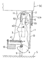
【図1】本発明に係る構造を有する跳上げシートの使用状態を示す側面図である。
【図2】図1の状態の斜視図である。
【図3】図1の状態の要部の斜視図である。
【図4】図3のIVーIV線断面図である。
【図5】図3の縦断面図である。
【図6】本発明に係る構造を有する跳上げシートを跳上げ状態の側面図である。
【図7】図6の状態の要部の斜視図である。
【符号の説明】
SC シートクッション
S ベース部材
1 後脚
2 連結ロッド
3 操作レバー
4 フック
5 ストライカ
6 カム片[0001]
BACKGROUND OF THE INVENTION
The present invention relates to a seat installed in a so-called box-type vehicle, and more particularly to a flip-up seat that can fold a seat back on a seat cushion when it is not in use and jump the seat cushion forward.
[0002]
[Prior art]
This type of conventional jumping seat is, for example, disclosed in Japanese Patent Application Laid-Open No. 57-104425, in which a front portion of a seat cushion is pivotally attached to a vehicle body side via a hinge so as to be pivotable. The rear part of the cushion is locked to the striker on the vehicle body side with a hook provided on the rear leg. The hook is configured to be unlocked by rotating an operation lever provided on the rear leg.
[0003]
The above operating lever is provided at the lower part of the rear seat side behind the rear leg, and can be unlocked from the rear seat side, and the rear leg is formed to be folded when the seat is flipped up. ing.
[0004]
[Problems to be solved by the invention]
In the above-mentioned jumping seat, since the operation lever is mounted in a protruding manner behind the rear leg, there is a possibility that the feet of the occupant seated on the rear seat and the load are in contact when the seat is used and when the seat is lifted up. .
[0005]
In addition, in the case where hooks are provided on the rear legs provided on the left and right sides of the seat cushion, the connecting rod for simultaneously rotating the left and right hooks is arranged near the vehicle floor where the seat cushion is installed. There also arises a problem that the seat occupant's feet interfere with the connecting rod.
[0006]
Therefore, an object of the present invention is to eliminate the problems of such conventional products.
[0007]
[Means for Solving the Problems]
In order to achieve the above object, a flip-up seat according to the present invention includes a seat cushion that pivotally attaches a front part to a base member and pivotally supports a pair of left and right rear legs so that the rear part can be folded. A jumping seat having a hook provided on each rear leg and locked to the striker of the base member, and an operation lever provided on an outer surface of the rear leg and unlocked by rotating forward by the hook. a is, the pair of right and left rear legs are connected together by a connecting rod, the co the provision of the hook to be biased by a spring in the folding direction of the rear leg to the connecting rod, the consolidated rods, Koashigai After the upper end of the operation lever arranged along the side surface is fixed, and a spring is provided on the operation lever to elastically hold the operation lever along the outer surface of the rear leg, and then the operation lever is folded. Rotate with the legs It is characterized by being stored on the bottom side of the seat .
[0008]
With the above configuration, the operating lever rotates together with the rear leg without protruding outward with respect to the rear leg in the use state and the raised state of the seat.
[0009]
Further, by fixing a cam piece to the connecting rod and rotating the hook through the cam piece, the connecting rod can be disposed at a position close to the bottom of the seat cushion, and the rear seat occupant The legs will not interfere.
[0010]
Furthermore, since the connecting rod is formed coaxially with the pivot shaft for folding the pair of left and right rear legs, the structure can be simplified and provided at low cost.
[0011]
DETAILED DESCRIPTION OF THE INVENTION
Hereinafter, an embodiment of the present invention will be described with reference to the drawings.
1, 2 and 6 show a flip-up sheet having a structure according to the present invention, which is a second sheet having a third sheet on the rear side, FIG. 1 and FIG. Each state is shown.
[0012]
The flip-up seat folds the seat back (SB) on the seat cushion (SC) so that the seat cushion (SC) pivots forward in a standing manner as shown in FIG. 6 with the hinge pin (72) as the center of rotation. It is configured.
[0013]
In the state of use, as shown in FIG. 1, the hook (4) attached to the rear legs (1) provided on the left and right of the rear bottom surface of the seat cushion (SC) stands up from the base member (S) (5 ) Is engaged and locked.
[0014]
The base member (S) is an upper rail of a slide rail or a vehicle body that moves and adjusts the seat in the front-rear direction.
Further, a hinge pin (72) pivotably attached to the front portion of the seat cushion (SC) is provided on the front leg (70) on the base member (S) side and the bracket (71) on the seat cushion (SC) side. Installed.
[0015]
As shown in FIG. 2, the pair of left and right rear legs (1) and (1) described above are attached to the mounting bracket (11) fixed to the left and right rear portions of the seat cushion (SC), with the connecting rod (2) as the center of rotation. As shown in FIGS. 3 to 5, the hook (4) and the hook (4) are rotated on the rear legs (1) and (1) to lock the striker (5). As shown in FIG. 3, the operating lever (3) for releasing the state and the mounting bracket (11) are formed in a U-shape having an opening in the front so that the rear leg (1) can be folded. The back part (11A) is used as a stopper to restrict the outward rotation of the rear leg (1).
[0016]
As shown in FIG. 4, each rear leg (1) (1) has a U shape with the opening facing forward, and a hook (4) and the like are accommodated therein, and a hook ( 4) is provided with a slit (13) that rotates when unlocked in the vertical direction.
A rod (not shown) that connects one end of the rear legs (1) and (1) to the base plate (70) described later is connected to the lower side so that the rear legs (1) and (1) are folded inward when the seat is lifted.
[0017]
As shown in FIG. 5, the hook (4) is attached so as to rotate by rotating the cam piece (6) fixed to the connecting rod (2). The rear leg (1) is biased in the folding direction. In the figure, (40) is the rotation center of the hook (4), and the hook (4) is rotated by a pin (61) provided on the cam piece (6).
[0018]
The operating lever (3) has an upper end integrally fixed to the connecting rod (2) on the outer surface of the rear leg (1), and the connecting rod (2) rotates by rotating the lower part forward. Then, the cam piece (6) is rotated in the rotation direction of the operation lever (3). Thereby, the hook (4) is in the reverse direction.
[0019]
The operation lever (3) is urged along the rear leg (1) by the elasticity of the spring (62). Since the operation lever (3) rotates forward about the connecting rod (2) as described above, the connecting rod (2) is connected to the operating lever (3) and the rear legs (1) (1). It becomes the rotation axis.
[0020]
In the figure, reference numerals (81) and (82) denote seat cushion cushion frames in which pipes are formed in a frame shape. Hinge brackets (71) are welded to the front left and right of the cushion frame (81). The hinge pin (72) is pivotally attached to the base plate (70) on the base member (S) side so as to be able to be raised.
The mounting bracket (11) is welded to the left and right of the cushion frame (82).
[0021]
As described above, since the present invention is configured, the operating lever (3) is placed on the outer surface of the rear leg (1) as shown in FIG . 3 and FIG. It is held by the elasticity of the spring (62) so as to be along the outer surface of the rear leg, and does not protrude forward or rearward from the outer surface of the rear leg (1).
[0022]
When the operation lever (3) is rotated forward, the connecting rod (2) is rotated, and the cam piece (6) integrated with the connecting rod (2) is rotated to pin the hook (4). In (61), it is rotated in the unlocking direction. Thereby, the hook (4) engaged with the striker (5) is detached from the striker (5), and the lock is released.
[0023]
In the locked state, the operation direction for unlocking the operating lever (3) is opposite to the unlocking direction of the hook (4), so that the operating lever (3) is subjected to a load from the rear. On the other hand, the hook (4) serves as a guard member. Even if a load in the same direction as the unlocking direction of the hook (4) acts on the operation lever (3), the lock by the hook (4) is not released.
[0024]
When the seat is lifted up as shown in FIG. 6 after the unlocking, as shown in FIG. 7, the operation lever (3) is rotated together with the rear leg (1) to be folded and folded to the bottom side of the seat. Thereby, the operation lever (3) is stored together with the rear leg (1) on the bottom side of the seat.
[0025]
【The invention's effect】
According to the first aspect of the present invention, the connecting rod that attaches the operation lever and connects the left and right rear legs integrally can be installed at a high position on the seat side, so that the foot of the rear seat occupant may interfere with the connecting rod. Absent.
Further, since the operation lever is mounted at a high position, the legs of the rear seat occupant do not interfere with the load, and the operability of the operation lever is improved.
In addition, since the operation lever is folded together with the rear leg, the operation lever does not protrude outward when the seat is in the raised state.
[0026]
According to the second aspect of the present invention, the operating lever can be provided at a high position away from the hook locked to the striker of the base member, and the connecting rod for fixing the operating lever can be set at a high position. it can.
[0027]
According to the third aspect of the present invention, a pivot shaft for pivoting the operation lever is not required, and the structure is simple and can be provided at low cost.
[0028]
According to the fourth aspect of the present invention, the operation lever is locked by the hook even if the hook acts as a guard against the load from the rear and the rear load in the unlocking direction of the hook acts on the operation lever. It is not released.
[Brief description of the drawings]
FIG. 1 is a side view showing a usage state of a flip-up sheet having a structure according to the present invention.
FIG. 2 is a perspective view of the state of FIG.
FIG. 3 is a perspective view of a main part in the state of FIG. 1;
4 is a cross-sectional view taken along line IV-IV in FIG.
FIG. 5 is a longitudinal sectional view of FIG. 3;
FIG. 6 is a side view of a jumping sheet having a structure according to the present invention.
7 is a perspective view of a main part in the state of FIG. 6. FIG.
[Explanation of symbols]
SC Seat cushion
Claims (4)
前記左右一対の後脚は連結ロッドで一体に連結し、該連結ロッドに後脚の折り畳み 方向にバネで付勢する前記フックを設けると共に、連結ロッドに、後脚外側面に沿っ て配設した前記操作レバーの上端を固着し、該操作レバーに、操作レバーを後脚の外 側面に沿うように弾力で保持するばねを設けて、操作レバーを折り畳まれる後脚と共 に回動させてシートの底部側に格納することを特徴とする跳上げシートの構造。A seat cushion pivotally attached to the base member to be pivotable and a pair of left and right rear legs pivotally supported at the rear; a hook provided on each of the rear legs and locked to the striker of the base member; A flip-up seat having an operation lever that is provided on an outer surface of the rear leg and pivots forward to unlock the hook.
Said pair of right and left rear legs are connected together by a connecting rod, the co The provision of the hook to be biased by a spring in the folding direction of the rear leg to the connecting rod, the consolidated rods, along the rear leg outer surface The upper end of the operating lever is fixed, and a spring is provided on the operating lever that elastically holds the operating lever along the outer side of the rear leg, and the operating lever can be rotated together with the rear leg to be folded. A structure of a flip-up sheet characterized by being stored on the bottom side of the sheet.
Priority Applications (1)
| Application Number | Priority Date | Filing Date | Title |
|---|---|---|---|
| JP2001384044A JP3784006B2 (en) | 2001-12-18 | 2001-12-18 | Structure of jumping sheet |
Applications Claiming Priority (1)
| Application Number | Priority Date | Filing Date | Title |
|---|---|---|---|
| JP2001384044A JP3784006B2 (en) | 2001-12-18 | 2001-12-18 | Structure of jumping sheet |
Publications (2)
| Publication Number | Publication Date |
|---|---|
| JP2003182421A JP2003182421A (en) | 2003-07-03 |
| JP3784006B2 true JP3784006B2 (en) | 2006-06-07 |
Family
ID=27593876
Family Applications (1)
| Application Number | Title | Priority Date | Filing Date |
|---|---|---|---|
| JP2001384044A Expired - Fee Related JP3784006B2 (en) | 2001-12-18 | 2001-12-18 | Structure of jumping sheet |
Country Status (1)
| Country | Link |
|---|---|
| JP (1) | JP3784006B2 (en) |
Families Citing this family (2)
| Publication number | Priority date | Publication date | Assignee | Title |
|---|---|---|---|---|
| US7152922B2 (en) * | 2004-05-07 | 2006-12-26 | Fisher Dynamics Corporation | Powered remote release actuator for a seat assembly |
| JP4525408B2 (en) * | 2005-03-25 | 2010-08-18 | アイシン精機株式会社 | Vehicle seat |
-
2001
- 2001-12-18 JP JP2001384044A patent/JP3784006B2/en not_active Expired - Fee Related
Also Published As
| Publication number | Publication date |
|---|---|
| JP2003182421A (en) | 2003-07-03 |
Similar Documents
| Publication | Publication Date | Title |
|---|---|---|
| JP4223495B2 (en) | Vehicle seat and vehicle with such a seat | |
| US5765894A (en) | Seat device for a vehicle | |
| JP3647408B2 (en) | Vehicle seat configuration | |
| JP3292626B2 (en) | Vehicle seat | |
| US20080203796A1 (en) | Vehicle seat | |
| JP4019456B2 (en) | Vehicle seat structure | |
| US7246857B2 (en) | Seat folding device of vehicle | |
| JP3784006B2 (en) | Structure of jumping sheet | |
| JP3977030B2 (en) | Seat cushion lock structure for flip-up type storage seat | |
| JP2002225603A (en) | Vehicle seat | |
| JP3606181B2 (en) | Vehicle seat | |
| JP2019064307A (en) | Vehicle seat | |
| JP2003040009A (en) | Vehicle seat with tip-up mechanism | |
| JP3287453B2 (en) | Locking device for jumping seat | |
| JP3281536B2 (en) | Two-stage hinge structure for vehicle seats | |
| JP2002347488A (en) | Seat for vehicle | |
| JP3977590B2 (en) | Storage sheet | |
| JP2874855B2 (en) | Vehicle foldable seat locking device | |
| JP2002219978A (en) | Vehicle seat | |
| JP3590018B2 (en) | Lever guide structure for jumping seat | |
| JP3121179B2 (en) | Automotive seat locking device | |
| JPH10147165A (en) | Jumping sheet | |
| JP3928192B2 (en) | Vehicle seat | |
| JP6708940B2 (en) | Vehicle seat | |
| JP3445498B2 (en) | Car seat equipment |
Legal Events
| Date | Code | Title | Description |
|---|---|---|---|
| A977 | Report on retrieval |
Free format text: JAPANESE INTERMEDIATE CODE: A971007 Effective date: 20050523 |
|
| A131 | Notification of reasons for refusal |
Free format text: JAPANESE INTERMEDIATE CODE: A131 Effective date: 20050721 |
|
| A521 | Written amendment |
Free format text: JAPANESE INTERMEDIATE CODE: A523 Effective date: 20050920 |
|
| TRDD | Decision of grant or rejection written | ||
| A01 | Written decision to grant a patent or to grant a registration (utility model) |
Free format text: JAPANESE INTERMEDIATE CODE: A01 Effective date: 20060123 |
|
| A61 | First payment of annual fees (during grant procedure) |
Free format text: JAPANESE INTERMEDIATE CODE: A61 Effective date: 20060124 |
|
| A61 | First payment of annual fees (during grant procedure) |
Free format text: JAPANESE INTERMEDIATE CODE: A61 Effective date: 20060310 |
|
| R150 | Certificate of patent or registration of utility model |
Free format text: JAPANESE INTERMEDIATE CODE: R150 |
|
| FPAY | Renewal fee payment (event date is renewal date of database) |
Free format text: PAYMENT UNTIL: 20090324 Year of fee payment: 3 |
|
| FPAY | Renewal fee payment (event date is renewal date of database) |
Free format text: PAYMENT UNTIL: 20100324 Year of fee payment: 4 |
|
| FPAY | Renewal fee payment (event date is renewal date of database) |
Free format text: PAYMENT UNTIL: 20110324 Year of fee payment: 5 |
|
| LAPS | Cancellation because of no payment of annual fees |