JP3748467B2 - Method and apparatus for aligning anchor material at a joint portion between a natural ground slope stabilization block and an anchor material for fixing the block to the natural ground - Google Patents
Method and apparatus for aligning anchor material at a joint portion between a natural ground slope stabilization block and an anchor material for fixing the block to the natural ground Download PDFInfo
- Publication number
- JP3748467B2 JP3748467B2 JP25947896A JP25947896A JP3748467B2 JP 3748467 B2 JP3748467 B2 JP 3748467B2 JP 25947896 A JP25947896 A JP 25947896A JP 25947896 A JP25947896 A JP 25947896A JP 3748467 B2 JP3748467 B2 JP 3748467B2
- Authority
- JP
- Japan
- Prior art keywords
- block
- anchor material
- eccentric
- eccentric liner
- liner
- Prior art date
- Legal status (The legal status is an assumption and is not a legal conclusion. Google has not performed a legal analysis and makes no representation as to the accuracy of the status listed.)
- Expired - Lifetime
Links
Images


Landscapes
- Pit Excavations, Shoring, Fill Or Stabilisation Of Slopes (AREA)
Description
【0001】
【発明の属する技術分野】
本発明は、地山斜面の安定化に関するものであり、特にその安定化を、地山斜面にブロックを設置し、このブロックをアンカー材によって地山に固定することによって達成するものに関し、更にその中でも、ブロックとアンカー材との結合部におけるアンカー材調心方法及び装置に関する。アンカー材の調心という用語は、本明細書では、アンカー材における張力の作用方向を、上記の結合部を含めて略々一線上に置くということを意味している。
【0002】
【従来の技術】
ブロックを設置することによる従来の地山斜面安定化の方法は例えば特開平6−17425号公報に示されている。この方法は図3に示すように、地山1の一部1aを切り取って設置面1bを形成し、次いでアンカーケーブル、アンカーロッドなどのアンカー材3を設置し、アンカー材3の定着後上記設置面1bにコンクリート製ブロック2を配置し、予め設置しておいたアンカー材3の頭部3aとブロック2とを結合し、アンカー材頭部3aに設けた締め付け手段6によりブロック2を設置面1bに対して押し付けて固定するものである。アンカー材3の設置は、地山の設置面1bから地中に向けて、ボーリングマシーン等の穿孔機によってアンカー孔1cを削孔し、次いでアンカー材3をアンカー孔に挿入し、アンカー材基部3bを、アンカー孔1c内に注入したセメント等の固結材3cによって固定することによって行われる。
【0003】
ブロック2には、その中央部に設けられるアンカー材との結合部に、アンカー材基部3bに向けて先細りのテーパ孔2aが形成されており、このテーパ孔にはこの孔のものと実質的に同じテーパを有する外周面を持つ截頭円錐台状のアンカー材頭部支持部材4が嵌め込まれる。アンカー材3は、アンカー材頭部支持部材4に設けた孔を通り抜けて同支持部材の頂面から突出しており、この突出部にはアンカー材を掴む手段5と、アンカー材に対して支持部材4をアンカー材基部3b方向へ締め付ける締付け手段6が取り付けられている。なお、図中7は、上記結合部が配置されている凹陥部2bを覆い、内部にある部材を保護する蓋である。
【0004】
【発明が解決しようとする課題】
上記のようにアンカー材を地山に設置する際、地山の状況や作業の仕方などの様々な原因により、アンカー材が地山設置面1bに対して常に直角に設置されるとは限らない。直角でない場合、ブロック2を設置面1bの所定の位置に配置し、アンカー材頭部3aとの結合を行ったとき、アンカー材3はその頭部3aとそれ以外の部分との間が屈曲した状態となり、張力の及ぶ方向が一線上にならないために、アンカー材3の支持作用が十分に発揮される状態とならず、好ましくない。そのため、従来、ブロック2のテーパ孔2aを、設置アンカー材3の延伸方向に合わせて偏向させて形成し、アンカー材頭部支持部材4をテーパ孔2aに嵌めた状態で、アンカー材頭部とそれ以外のアンカー材部分とが一線上に調心されるような方策が執られている。しかしながら、テーパ孔2aをアンカー材3の設置状況に合わせて、その都度そのように偏向させて形成することは、作業、時間、経費の何れの面においても極めて不利である。
【0005】
従って本発明の課題は、ブロックのテーパ孔を調整変更することなく、簡単且つ任意にアンカー材の調心ができるようにする方法及び装置を提供することである。
【0006】
【課題を解決するための手段】
上記の課題は、本発明によれば、ブロックに設けたテーパ孔に適合する外周面を有し、アンカー材頭部支持部材が嵌合するテーパ孔を偏心的に有している偏心ライナーを使用し、予め設置してあるアンカー材と設置面に配置したブロックとの結合部におけるブロックテーパ孔に上記の偏心ライナーを嵌め、偏心ライナーテーパ孔の中心線がアンカー材の延伸方向と同じ方向になるように偏心ライナーをブロックテーパ孔内で回転させることによって解決される。
【0007】
この方法によれば、上記のような偏心ライナーを用い、この偏心ライナーをブロックテーパ孔内で回転調節するだけでアンカー材の調心(アンカー頭部の角度調整)ができるので、ブロックテーパ孔の軸心の角度がアンカー材の延伸方向に合うように調整したブロックをその都度準備することなく、迅速且つ簡単に且つ安価に調心作業が達成できる。
【0008】
また、上記の課題は、本発明によれば、ブロックに設けたテーパ孔に適合する外周面を有し、且つ偏心テーパ孔を有している偏心ライナーと、この偏心ライナーのテーパ孔に嵌合するアンカー材頭部支持部材とを有する装置によって達成できる。
【0009】
この装置によれば、従来構成のブロックに対して偏心ライナーを付加して使用するだけで、アンカー材の調心を自在に行うことができる。
【0010】
ブロックテーパ孔の横断面形状を円形とする代わりに多角形とし、偏心ライナーの外周面も同様の多角形の角錐形とすれば、アンカー頭部の角度調整は段階的なものとなるが、一旦角度調整された偏心ライナーはブロックテーパ孔内で回動することなく、調整状態に維持される。
【0011】
【発明の実施の形態】
以下添付図面の図1及び2を参照して本発明の実施の形態を説明する。なお、図3に示す部材と同じ部材には同じ符号を付して、詳細な説明を省略する。
【0012】
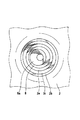
図1はブロック2のアンカー材との結合部を縦断面にて示しており、図2は図1のブロックの平面図である。
【0013】
ブロック2は従来のものと同様にコンクリート製であって、全体的に略十字形または矩形形状を有している。ブロック2の中央部には上方へ向かって拡開している凹陥部2bが形成され、この凹陥部の底部2cと地表面に接する底面2dとの間にはブロック2の厚さ方向に貫通するテーパ孔2aが形成されている。図示の実施形態では、このテーパ孔2aは、補強用として設けた鉄製で漏斗状の保護材2eの内周面によって形成されている。
【0014】
上記のテーパ孔2aには偏心ライナー8が嵌合している。この偏心ライナーはテーパ孔2aに適合する外周面を有し、且つ截頭円錐台形のアンカー材頭部支持部材4が嵌合するテーパ孔8aを偏心的に有している。従って、テーパ孔8aの中心線8bはブロックテーパ孔2aの中心線2a1に対して角度θを成しており、この角度θは偏心ライナー8をテーパ孔2a内で回転させて相対位置を変更しても常に一定に維持される。この角度θは偏心テーパ孔8aの中心線の傾きが異なる他の偏心ライナーを用いることにより変更することができる。
【0015】
明らかなように、支持部材4の外周テーパ面とテーパ孔8のテーパ面とは同じ円錐面上にある。偏心ライナー8は金属製であることが好ましいが、プラスチックやその他の材料で製作したものであってもよい。
【0016】
ブロックテーパ孔2aを多角形の角錐形とし、これに合わせて偏心ライナー8の外周面も多角形の角錐形としてもよい。
【0017】
ブロック2の設置作業を行う場合、まずブロック2が地山の設置面1b(図3参照)の所定箇所に定置され、それと共に、予め設置してあるアンカー材3(図3参照)の頭部がブロック2の底面2dの側より偏心ライナーテーパ孔8a内に引き込まれる。次にアンカー材3の延伸方向と偏心ライナーテーパ孔8aの中心線が同方向若しくは略同方向になるように偏心ライナー8がブロックテーパ孔2a内で回転せしめられる。偏心ライナーのこのような回転によっても、両者が同方向にならない場合には、当該偏心ライナーはテーパ孔8aの中心線8bの傾きが異なる他の偏心ライナー8に取り換えられる。どの偏心ライナーを使用するかは、ブロック設置面1bとアンカー材3との間の成す角度によって見当をつけることができる。設置面1bとアンカー材3との間の角度が直角乃至はそれに近い場合には、偏心ライナーに代えて、テーパ孔8aが同心的に設けられたライナーが使用される。
【0018】
偏心ライナー8の上記のような角度位置の調整後、偏心ライナーテーパ孔8a内に嵌挿されるアンカー材頭部支持部材4に軸線方向に設けた貫通孔にアンカー材頭部が挿通され、次いで支持部材4から上方へ突出したアンカー材部分が掴み手段5(図3)によって掴まれ、次いで締付け手段6により、支持部材4に対してアンカー材を上方へ引き出すように相対移動させることによって、アンカー材は緊張されると共に、支持部材4は偏心ライナー8及びブロック2と一体化され、それと共にブロック2が地山の設置面1bに押し付けられ、ブロック2の設置が完了する。
【0019】
【発明の効果】
上記のように本発明によれば、適当な軸線の傾きを有するテーパ孔を持つ偏心ライナーを選択し、それをブロックテーパ孔内で回転させることによってアンカー材の調心が達成されるので、調心のためのコストが比較的安価になり、また調心作業も簡単に行うことができ、従ってブロックの経済的で迅速な設置が可能となり、またブロック自体は均一のものを製作すればよいので安価に大量生産することができる。
【図面の簡単な説明】
【図1】本発明によるアンカー材調心方法及び装置を示す、ブロック中央部の縦断面図である。
【図2】アンカー材頭部支持部材を取り除いた状態での図1の平面図である。
【図3】地山斜面に設置されたブロックとアンカー材との関係を示す、断面図である。
【符号の説明】
1 ‥‥ 地山
1b‥‥ ブロック設置面
1c‥‥ アンカー孔
2 ‥‥ ブロック
2a‥‥(ブロックの)テーパ孔
2d‥‥(ブロックの)底面
3 ‥‥ アンカー材
3a‥‥ アンカー材頭部
4 ‥‥ アンカー材頭部支持部材
5 ‥‥(アンカー材頭部の)掴み手段
6 ‥‥ 締付け手段
8 ‥‥ 偏心ライナー
8a‥‥(偏心ライナーの)テーパ孔[0001]
BACKGROUND OF THE INVENTION
The present invention relates to stabilization of a natural slope, and more particularly to the stabilization of the natural slope by installing a block on the natural slope and fixing the block to the natural ground with an anchor material. In particular, the present invention relates to an anchor material alignment method and apparatus at a joint between a block and an anchor material. In the present specification, the term “alignment of the anchor material” means that the action direction of the tension in the anchor material is substantially aligned with the above-described joint portion.
[0002]
[Prior art]
A conventional method for stabilizing natural slopes by installing blocks is disclosed in, for example, Japanese Patent Application Laid-Open No. 6-17425. In this method, as shown in FIG. 3, a part 1 a of the natural ground 1 is cut to form an
[0003]
The
[0004]
[Problems to be solved by the invention]
When the anchor material is installed on the natural ground as described above, the anchor material is not always installed at a right angle with respect to the natural
[0005]
SUMMARY OF THE INVENTION Accordingly, an object of the present invention is to provide a method and an apparatus that can easily and arbitrarily align an anchor material without adjusting and changing a tapered hole of a block.
[0006]
[Means for Solving the Problems]
According to the present invention, an eccentric liner having an outer peripheral surface adapted to a tapered hole provided in a block and having an eccentric taper hole into which an anchor material head support member is fitted is used according to the present invention. Then, the eccentric liner is fitted into the block taper hole in the joint portion between the anchor material installed in advance and the block arranged on the installation surface, and the center line of the eccentric liner taper hole is in the same direction as the extending direction of the anchor material. This is solved by rotating the eccentric liner in the block taper hole.
[0007]
According to this method, since the eccentric liner as described above is used, and the eccentric liner can be adjusted by simply rotating and adjusting the eccentric liner within the block taper hole, the angle of the anchor head can be adjusted. The alignment operation can be achieved quickly, easily and inexpensively without preparing a block adjusted so that the angle of the shaft center matches the extending direction of the anchor material each time.
[0008]
Further, according to the present invention, the above-described problem is that an eccentric liner having an outer peripheral surface adapted to a tapered hole provided in the block and having an eccentric tapered hole is fitted into the tapered hole of the eccentric liner. This can be achieved by a device having an anchor material head supporting member.
[0009]
According to this device, alignment of the anchor material can be performed freely only by adding an eccentric liner to the block having the conventional configuration.
[0010]
If the cross-sectional shape of the block taper hole is a polygon instead of a circle, and the outer peripheral surface of the eccentric liner is a similar polygonal pyramid, the angle adjustment of the anchor head will be gradual. The eccentric liner whose angle is adjusted is maintained in the adjusted state without rotating in the block taper hole.
[0011]
DETAILED DESCRIPTION OF THE INVENTION
Embodiments of the present invention will be described below with reference to FIGS. 1 and 2 of the accompanying drawings. In addition, the same code | symbol is attached | subjected to the same member as the member shown in FIG. 3, and detailed description is abbreviate | omitted.
[0012]
FIG. 1 is a longitudinal sectional view showing a connecting portion of the
[0013]
The
[0014]
An
[0015]
As is apparent, the outer peripheral tapered surface of the support member 4 and the tapered surface of the
[0016]
The
[0017]
When performing the installation work of the
[0018]
After adjusting the angular position of the
[0019]
【The invention's effect】
As described above, according to the present invention, the alignment of the anchor material is achieved by selecting an eccentric liner having a taper hole having an appropriate axis inclination and rotating it in the block taper hole. The cost for the heart is relatively low, and the alignment work can be performed easily. Therefore, the block can be installed economically and quickly, and the block itself can be manufactured uniformly. It can be mass-produced at low cost.
[Brief description of the drawings]
FIG. 1 is a longitudinal sectional view of a central portion of a block showing an anchor material aligning method and apparatus according to the present invention.
FIG. 2 is a plan view of FIG. 1 with an anchor material head support member removed.
FIG. 3 is a cross-sectional view showing the relationship between a block installed on a natural slope and an anchor material.
[Explanation of symbols]
1 ...
Claims (3)
Priority Applications (1)
| Application Number | Priority Date | Filing Date | Title |
|---|---|---|---|
| JP25947896A JP3748467B2 (en) | 1996-09-30 | 1996-09-30 | Method and apparatus for aligning anchor material at a joint portion between a natural ground slope stabilization block and an anchor material for fixing the block to the natural ground |
Applications Claiming Priority (1)
| Application Number | Priority Date | Filing Date | Title |
|---|---|---|---|
| JP25947896A JP3748467B2 (en) | 1996-09-30 | 1996-09-30 | Method and apparatus for aligning anchor material at a joint portion between a natural ground slope stabilization block and an anchor material for fixing the block to the natural ground |
Publications (2)
| Publication Number | Publication Date |
|---|---|
| JPH10102498A JPH10102498A (en) | 1998-04-21 |
| JP3748467B2 true JP3748467B2 (en) | 2006-02-22 |
Family
ID=17334646
Family Applications (1)
| Application Number | Title | Priority Date | Filing Date |
|---|---|---|---|
| JP25947896A Expired - Lifetime JP3748467B2 (en) | 1996-09-30 | 1996-09-30 | Method and apparatus for aligning anchor material at a joint portion between a natural ground slope stabilization block and an anchor material for fixing the block to the natural ground |
Country Status (1)
| Country | Link |
|---|---|
| JP (1) | JP3748467B2 (en) |
Families Citing this family (1)
| Publication number | Priority date | Publication date | Assignee | Title |
|---|---|---|---|---|
| JP6214295B2 (en) * | 2013-09-17 | 2017-10-18 | 積水テクノ成型株式会社 | Pressure receiving structure |
-
1996
- 1996-09-30 JP JP25947896A patent/JP3748467B2/en not_active Expired - Lifetime
Also Published As
| Publication number | Publication date |
|---|---|
| JPH10102498A (en) | 1998-04-21 |
Similar Documents
| Publication | Publication Date | Title |
|---|---|---|
| EP1837128B1 (en) | Drill and drilling method | |
| US6298611B1 (en) | Ground anchor with self-aligning compression cap | |
| US20090170627A1 (en) | Ferrule and golf club incorporating same | |
| JPS63261032A (en) | Fixing apparatus | |
| JPH08100810A (en) | Fixing element with nail and biasing element | |
| JP3748467B2 (en) | Method and apparatus for aligning anchor material at a joint portion between a natural ground slope stabilization block and an anchor material for fixing the block to the natural ground | |
| JPS6135903A (en) | Twist drill | |
| US5063724A (en) | Anchor for fixing rod in concrete and the like | |
| JP3155479B2 (en) | Polymer insulator | |
| JPH11510230A (en) | Method of putting ground anchor in the ground and anchor used for it | |
| JP2586052Y2 (en) | Anchor pedestal | |
| JP3050075B2 (en) | Machining tool with inner wall shape for mounting hole for embedded member | |
| JPH11127908A (en) | Spike for shoes and shoe sole structure using the spike | |
| EP3102740A1 (en) | Pile shoe and pile | |
| JP3771134B2 (en) | Anchor device | |
| JPS639703Y2 (en) | ||
| AU2012201743A1 (en) | Anchor rod | |
| KR102722004B1 (en) | the improved expandable type anchor structure | |
| JPH0223323B2 (en) | ||
| JPH0437956Y2 (en) | ||
| GB2182995A (en) | Anchors | |
| JP2001263000A (en) | Support tool for suspending heavy matter into tunnel, support structure using the same, and construction method therefor | |
| JP2001020289A (en) | Anchor fixing pedestal for use in slope surface stabilizing method | |
| JPH07243213A (en) | Bearing plate device for ground anchor | |
| JP2552517B2 (en) | Anchor body sheath of ground anchor |
Legal Events
| Date | Code | Title | Description |
|---|---|---|---|
| A977 | Report on retrieval |
Free format text: JAPANESE INTERMEDIATE CODE: A971007 Effective date: 20051110 |
|
| TRDD | Decision of grant or rejection written | ||
| A01 | Written decision to grant a patent or to grant a registration (utility model) |
Free format text: JAPANESE INTERMEDIATE CODE: A01 Effective date: 20051115 |
|
| A61 | First payment of annual fees (during grant procedure) |
Free format text: JAPANESE INTERMEDIATE CODE: A61 Effective date: 20051128 |
|
| R150 | Certificate of patent or registration of utility model |
Free format text: JAPANESE INTERMEDIATE CODE: R150 |
|
| FPAY | Renewal fee payment (event date is renewal date of database) |
Free format text: PAYMENT UNTIL: 20091209 Year of fee payment: 4 |
|
| FPAY | Renewal fee payment (event date is renewal date of database) |
Free format text: PAYMENT UNTIL: 20101209 Year of fee payment: 5 |
|
| FPAY | Renewal fee payment (event date is renewal date of database) |
Free format text: PAYMENT UNTIL: 20101209 Year of fee payment: 5 |
|
| FPAY | Renewal fee payment (event date is renewal date of database) |
Free format text: PAYMENT UNTIL: 20111209 Year of fee payment: 6 |
|
| FPAY | Renewal fee payment (event date is renewal date of database) |
Free format text: PAYMENT UNTIL: 20111209 Year of fee payment: 6 |
|
| FPAY | Renewal fee payment (event date is renewal date of database) |
Free format text: PAYMENT UNTIL: 20121209 Year of fee payment: 7 |
|
| FPAY | Renewal fee payment (event date is renewal date of database) |
Free format text: PAYMENT UNTIL: 20121209 Year of fee payment: 7 |
|
| FPAY | Renewal fee payment (event date is renewal date of database) |
Free format text: PAYMENT UNTIL: 20131209 Year of fee payment: 8 |
|
| R250 | Receipt of annual fees |
Free format text: JAPANESE INTERMEDIATE CODE: R250 |
|
| R250 | Receipt of annual fees |
Free format text: JAPANESE INTERMEDIATE CODE: R250 |
|
| R250 | Receipt of annual fees |
Free format text: JAPANESE INTERMEDIATE CODE: R250 |
|
| EXPY | Cancellation because of completion of term |